1
Integration Document
Promag 53 Flowmeter via EtherNet/IP to the
PlantPAx Process Automation System
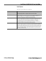
Topic
Page
Preferred Integration
2
Application Overview
4
Example System
8
Installation
9
Configure the E+H Promag 53 Flowmeter with the AOP
21
Visualization – Using AOIs and Faceplates
30
Configure the E+H Promag 53 Flowmeter
(Optional Methods)
34
Appendix: View the IP Configuration Using the Promass 83 Local 45
Display
Additional Resources
47
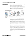
Preferred Integration
Rockwell Automation and Endress+Hauser have strengthened their strategic
alliance to provide complete process automation solutions that use
best-in-class instrumentation, software, and control systems.
There are hundreds of different components in a typical plant: controllers,
remote I/O, electrical drives, safety equipment, and sensors. Each must be
integrated, configured, and optimized during start-up and operation.
Recognizing the challenges this creates, Rockwell Automation and
Endress+Hauser are focused on providing scalable, off-the-shelf solutions.
To reduce the risks associated with integrating many devices from many
different suppliers, Rockwell Automation pretests many third-party
manufactured HART, FOUNDATION Fieldbus, EtherNet/IP, and
PROFIBUS PA field devices in the system test laboratory for compatibility
with the Rockwell Automation PlantPAx automation system. Each field device
is connected to the PlantPAx system and is subjected to interoperability testing
procedures similar to operating procedures in your plant. The results of each
field test are recorded in a test report for integration planning purposes.
For Endress+Hauser field devices, an additional step provides an “Integration
Document” and “Interoperability Statement” for each tested instrument. The
Integration Document provides information on installation, configuration,
startup, and operation of the integrated system. The Interoperability Statement
is assurance that the Endress+Hauser field device meets PlantPAx system
interoperability performance measures, as jointly established by Rockwell
Automation and Endress+Hauser and verified through completion of
common test procedures performed by either company. Both the Integration
Document and Interoperability Statement help reduce risk and provide ease of
integration.
The overall mission of the alliance is to provide proven solutions that combine
field instrumentation with fieldbus networks, such as HART, FOUNDATION
Fieldbus, PROFIBUS PA, and EtherNet/IP networks, with asset management
capabilities and Rockwell Automation’s system capabilities to provide a total
engineered solution.
Through preferred integration and support of increasing requirements for
plant-wide control, the alliance offers the following benefits:
• Reduced integration costs throughout engineering, commissioning, and
start-up
• Optimized plant availability and output
• Ensured product quality and consistency
• Optimized traceability to meet regulatory demands
• Predictive maintenance through intelligent instruments
For new construction, process improvements at an existing plant, or operating
cost reductions, the alliance delivers the following:
• Certified integration reduces risk, reduces integration costs, and protects
investment with pre-engineered interoperability.
Both companies believe open systems and standardized interfaces bring
maximum benefits.
• Advanced capabilities with plant-wide asset management provides better
visibility of plant health and easier access to instrument diagnostics,
which ultimately leads to faster troubleshooting and improves
decision-making.
Application Overview
This document provides a step-by-step approach to integrating an
Endress+Hauser Promag 53 Electromagnetic Mass Flow Measuring System into
a Rockwell Automation PlantPAx process automation system via EtherNet/IP.
This Section
Describes
Application overview
Details about the field instrument and control system.
Example system
Specifications on the required hardware and software components.
Installation
How to:
• Connect the measurement instrument to the EtherNet/IP interface.
• Configure the EtherNet/IP interface.
Configuration
How to:
• Configure the measurement instrument using the Add-On Profile (AOP).
• Configure the measurement instrument using two optional methods: the quick setup
menus on the local display or the Webserver.
Visualization
How to implement and configure a graphical display of device information.
The ControlLogix platform provides a robust EtherNet/IP backbone for
communication to process fieldbus networks. The PlantPAx system
architecture uses producer/consumer technology, allowing input information
and output status to be shared by all ControlLogix controllers in the system.
This integration document assumes you have a working knowledge of
ControlLogix systems. For more details regarding the equipment and tasks
described in this document, see Additional Resources on page 47.
Promag Flowmeter
Promag measuring instruments offer you cost-effective flow measurement
with a high degree of accuracy for a wide range of process conditions. Promag
sensors, tried and tested in thousands of applications, offer the following:
No pressure loss
Not sensitive to vibrations
Simple installation and commissioning
Modular device and operating concept resulting in a higher degree of
efficiency
Software options for batching, electrode cleaning and for measuring
pulsating flow
High degree of reliability and measuring stability
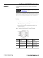
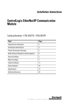
The measuring principle is based on Faraday's law of magnetic induction, a voltage
is induced in a conductor moving through a magnetic field.
In the electromagnetic measuring principle, the flowing medium is the
moving conductor. The voltage induced is proportional to the flow velocity
and is supplied to the amplifier by means of two measuring electrodes. The
flow volume is calculated by means of the pipe cross-sectional area. The DC
magnetic field is created through a switched direct current of alternating
polarity.
Ue = B•L•v
Q = A•v
Ue
B
L
v
Q
A
I
Induced voltage
Magnetic induction (magnetic field)
Electrode spacing
Flow velocity
Volume flow
Pipe cross-section
Current strength
Measuring System
The measuring system consists of a transmitter and a sensor.
Two versions are available:
Compact version: Transmitter and sensor form a mechanical unit.
Remote version: Sensor is mounted separate from the transmitter.
Transmitter:
Promag 53 ("Touch Control" without opening the housing, fourline display, unilluminated)
Sensor:
Promag W (DN 25 to 2000 / 1 to 78")
Measured Variable
Flow velocity (proportional to induced voltage)
Instrument Specifications
• Communication: Standard, EtherNet/IP™ up to 100 Mbps
– ODVA™ compliant
– IEEE 802.3
• Power supply option: 16 to 62 VDC, 85 to 260 VAC, 20 to 55 VAC
• Ambient temperature: -20 to +80 °C (-4 to +176 °F)
• Degree of protection: IP 67 (NEMA 4X), IP 68 (NEMA 6P)
• Approvals: CE marked for nonhazardous area application, ATEX
• EMC: IEC/EN 61326 and NAMUR Recommendation NE21
• Certified – Class 1, Div 2; CSA/FM
• Device configuring: Multiple options
• Ethernet connection: (2) RJ-45 female sockets, optional prewired
bus plug, or customer terminated wiring:
– Bus Plug: 4-pole M12 connector per IEC 61076-2-10
– RJ-45 plug and cable (not supplied)
• Cable entry options: Threaded ½ inch NPT, G Thread ½, M20 gland
• IP Addressing: Configurable EtherNet/IP and Webserver addresses
– Hardware device addressing by DIP switches
– Software device addressing by integrated Webserver
– DHCP or Static IP addressing supported
• Status condition: Four LEDs for communication status
• Security: Password protected with four definable levels
• Data mapping: (16) Autoscan registers for data transmission:
– Preconfigured for easy integration
– Allows change to user parameter if needed
– Positions 1 to 10 for input value reporting
– Positions 11 to 16 for output control
• Integrated Web server: Operation supported in standard web browser
• EDS file: Embedded in the device for RSLogix 5000 integration
• Add-on profile: Available for Promag 53 with EtherNet/IP
IMPORTANT
The use of DLR requires Stratix 4000 EtherNet Tap.
Control System
The control system includes these components:
Component
Description
Controller
The Logix controller is a modular, high performance controller, which uses RSLogix
5000 programming software to configure, program, and monitor a system.
EtherNet/IP Communication
The EtherNet/IP Communication Module serves as a linking device/bridge module.
Seamless integration into control systems with direct EtherNet/IP connection, e.g.,
ControlLogix, CompactLogix or PlantPAx from Rockwell Automation.
Programming software
PlantPAx is an easy object-oriented, explorer-based, drag-and-drop configuration that
allows you to build complex process functions. Furthermore, the software allows you to
mix and match IEC61131-3 compliant programming languages. All supported
programming languages share the same development environment, tag database, and
user interface, resulting in reduced training and higher productivity.
Visualization software
FactoryTalk® View Site Edition software is an HMI software program for monitoring,
controlling, and acquiring data from manufacturing operations throughout an enterprise. A
faceplate provides a graphical representation of the instrument through the Operator Work
Station. Faceplates associated with every instruction help you set up, tune and control the
element with a minimum of effort. Additions and modifications can be performed online,
while your process keeps running.
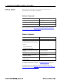
Example System
Endress+Hauser and Rockwell Automation interoperability testing is
performed for every new device and product.
Hardware Components
Component
Catalog Number
Promag 53 Electromagnetic Flowmeter
8-ANESAAAACCAA
EtherNet/IP Communications Module
1756-EN2T
ControlLogix Control System
1756-L63
For further details, see the PlantPAx Process Automation System Selection
Guide, publication PROCES-SG001-EN-P.
Software Components
Component
Catalog Number
PlantPAx
RSLogix 5000 Enterprise Series
programming software, Professional edition
9324-RLD700NXENE
Includes:
• RSLinx Classic software
• RSLinx Enterprise software
FactoryTalk View Site Edition (SE) software
(optional)
9701-VWSXXXXXENE
FactoryTalk AssetCentre server (optional)
9515-ASTSRVRENE
FactoryTalk AssetCentre process device
configuration (optional)
9515-ASTPRDCFENE
E+H FieldCare Standard Asset Management
software (optional)
SFE500
For additional information on drivers, see Additional Resources on page 47.
For specifications of the engineering workstation (EWS) and operator
workstation (OWS), see the PlantPAx Process Automation System Reference
Manual, publication PROCES-RM001.
Installation
The information in this section provides a summary of the installation
procedures.
IMPORTANT
For complete installation instructions, including warnings, see
Additional Resources on page 47.
Installation can be accomplished by either traditional methods or by utilizing
fieldbus connectors (optional). In this section, both methods are described to
allow you to choose the installation method best suited to the application.
Overview
Refer to the figures in this section when using the installation instructions.
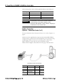
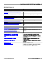
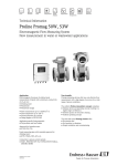
• Figure 1 provides an overview of three possible connection versions
when installing the Promag 53 Flowmeter.
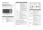
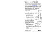
• Figure 2 shows the structure of the dual Ethernet module of the
Promag 53 Flowmeter.
Figure 1: Transmitter Cable Entries on the Promag 53 Flowmeter
Connection
Version 1
Connection
Version 2
Connection
Version 3
a
Ethernet via
cable entry/cable gland
Ethernet via
fieldbus connector
Ethernet via
fieldbus connector
b
Dummy plug
Dummy plug
Ethernet via
fieldbus connector
c
Power supply via
cable entry/cable gland
Power supply via
Power supply via
cable entry/cable gland cable entry/cable gland
Connector
Figure 2: Structure of the Dual Ethernet Module
Part
Description
a
Ethernet port 1 for EtherNet/IP network or Webserver
b
Ethernet port 2 for EtherNet/IP network or Webserver
c
Status light emitting diodes (LED)
d
DIP switches for hardware addressing
e
DIP switches to reset software addressing
f
Power supply connection
g
Port for service interface FSA193 (FieldCare)
Connect a Promag 53 Flowmeter
(Typical Procedure – Connection Version 1)
For illustrations, refer to the figures in Installation Overview on pages 9 and
10.
1. Unscrew the solid metal cover (side) of the electronics compartment
from the transmitter housing.
2. Push the power supply cable (Figure 1c) and the Ethernet cable
(Figure 1a) through the cable glands.
3. Tighten the cable glands.
4. Unplug the terminal connector (Figure 2f), remove it from the
transmitter housing, and then connect the power supply cable.
Power Supply Specifications
85 to 260 VAC, 20 to 55 VAC, or 16 to 62 VDC
• Terminal No. 1: L1 for AC; L+ for DC
• Terminal No. 2: N for AC; L- for DC
5. Plug the terminal connector (Figure 2f) into the transmitter housing.
6. Secure the ground cable to the ground terminal.
7. Secure the RJ45 plug on the Ethernet cable to Ethernet port 1
(Figure 2a).
The opposite end of the Ethernet cable is connected to the network.
8. Secure the ground cable to the ground terminal.
IMPORTANT
Between the stripped cable and the ground terminal, the cable
shielding should not exceed a length of 5 mm (0.20 in).
9. Screw the cover of the electronics compartment onto the transmitter
housing.
Verify Grounding and Shielding
If the EtherNet/IP cable is routed directly into the measuring device through
the cable entry (a fieldbus connector is not used), ensure that the grounding
and shielding are correct. This is required to guarantee electromagnetic
compatibility (EMC).
Connect the Ethernet Port
The measuring device has a dual Ethernet module to connect it to an
EtherNet/IP network and to connect it to a Webserver integrated in the
measuring device. It uses the EtherNet/IP communication protocol (Ethernet
Industrial Protocol) in accordance with the ODVA specification.
If you want to establish a connection to the EtherNet/IP network and to the
Webserver, you can use the two Ethernet ports. The ports are assigned using
the individual IP addresses.
The measuring device has the following default addresses when delivered:
Address Type
EtherNet/IP Network
Webserver
IP address
192.168.212.212
192.168.212.213
Netmask
255.255.255.0
255.255.255.0
Gateway
192.168.212.212
192.168.212.213
IMPORTANT
A connection label in the cover of the connection compartment
provides information on the default IP addresses and the
device-specific MAC addresses. If a new IP address is assigned, you
can document this on the connection label.
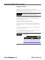
Fieldbus Connectors
(Optional – Connection Version 2 or 3)
For more information about Connection Version 2 or 3, refer to Figure 1 on
page 9.
The device can be supplied with an optional, ready-mounted M12 fieldbus
connector that is connected to the internal Ethernet port of the device using
an RJ45 plug. Fieldbus connectors for retrofitting can be ordered from
Entress+Hauser as a spare part. For more information, contact
Endress+Hauser Support, as described on the last page of this document.
Pair 11
Pair
Pair
Pair 22
2
2
33
1
1
4
4
M12 Plug
M 12 Plug
RJ45 Plug
RJ45 Plug
4-pole M12 Port with an RJ45 Plug
Signal
Name
Pin RJ45
Pin M12
TD+
Transmit Data +
1
1
TD-
Transmit Data -
2
3
RD+
Receive Data +
3
2
RD-
Receive Data -
6
4
Interpret the Status LED Signals
1
2
Status LEDs
3
4
The status LEDs are located in the dual Ethernet module, as shown in Figure 2c
on page 10. Use the following information to interpret the signals from the
status LEDs:
LED
Signal
1
Not used
2
Not used
3
Steady off
Significance
The device does not have an IP
address. or
The device is without a power supply.
Flashing green
The device has no established connection, but has
obtained an IP address.
Steady green
The device has at least one established connection.
(This may include the message router.)
Flashing red
One or more of the connections in which the device
is the target has a time out.
This signal does not turn off until all connections are
reestablished or the device is reset.
4
Steady off
The device is without a power supply.
Flashing green
No I/O connection is established.
or
Any established I/O connection is in idle mode (1 Hz).
Steady green
All established I/O connections are in run mode.
Configure the IP Address
The IP address of the measuring device can be configured for the
EtherNet/IP network through software settings or through the Dual In-line
Package (DIP) switches for hardware addressing.
IMPORTANT
The preferred method for configuring the IP address is using the
BootP/DHCP Server software, as described on page 15.
The IP address for software addressing is active when the device leaves the
factory (default IP address: 192.168.212.212), and all the DIP switches for
hardware addressing are set to OFF.
Dynamic Host Configuration Protocol (DHCP) Client
If a DHCP server is used within the EtherNet/IP network, the IP address,
gateway and subnet mask are set automatically when the DHCP client function
is enabled.
The MAC address of the measuring device is used for identification purposes.
(See also the connection label.)
You can enable the DHCP client function in the “Network Configuration”
menu of the Webserver, which is described on page 40.
IMPORTANT
• The measuring device has the following DHCP default settings
when delivered:
• The DHCP client function is disabled if hardware addressing is
enabled. If you need to disable the hardware addressing, refer to
Disable Hardware Addressing and Enable Software Addressing
on page 18.
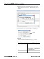
BOOTP/DHCP Server Software (preferred)
You can use any DHCP server, such as the Rockwell Automation
BOOTP/DHCP Server (BOOTP) to set up the network parameters for the
Ethernet link on the Promag 53 Flowmeter.
To configure the linking device using BOOTP/DHCP Server, perform the
following steps:
1. If possible, disable any virus protection that may be running. This can
affect the connection process.
2. Select Start > Programs > Rockwell Software > BOOTP-DHCP Server >
BOOTP-DHCP Server.
BOOTP/DHCP Server opens and sends the device a request for a
connection.
If additional devices are on your network, you may see other devices in
the Request History or Relation lists.
3. Access the MAC address of the Promag 53 using the local display or
the documentation that arrived with the device.
To access the MAC address on the local display, select SUPERVISION >
VERSION INFO > ETHERNET.
4. Double-click the request with the Promag 53 MAC address in the
Request History section of the screen, and the New Entry screen is
displayed.
5. In the New Entry screen, type the IP address for the Promag 53.
IP Address
6. Click OK.
The device is added to the Relation List section of the screen.
7. Depending on your preference, perform the appropriate task:
If you want to...
Then...
permanently assign the
configuration to the Promag 53
select the address in the Relation List section
of the screen and click Disable BOOTP/DHCP.
When you cycle power to the linking device, it
uses the configuration you assigned and does
not issue a DHCP request.
enable DHCP for the linking
device
select the device and click Enable DHCP.
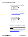
DIP Switches for Hardware Addressing
If you do not want to configure the IP address through software settings, you
can configure the IP address of the measuring device for the EtherNet/IP
network using the DIP switches. The permitted addresses are in the range
0 to 254. (The address 255 is reserved for the broadcast address.)
Hardware Addressing
The DIP switches can configure the last three digits (last octet) of the
IP address, represented by the X’s in the following: 192.168.212.XXX.
The first nine decimal digits (first three octets) can be configured only
through software addressing.
IMPORTANT
1. Refer to the example in step 2 below and set the desired IP address
using the corresponding DIP switches.
2. Wait 10 seconds, and the hardware addressing with the defined IP
address is activated.
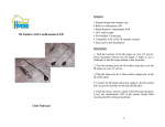
Example of Hardware Addressing for Address 97
1
ON
OFF
8
7
6
5
DIP
Switch
Position
Value
128
64
Off
On
0
64
32
On
32
16
Off
0
8
Off
0
4
Off
0
2
Off
0
1
On
1
Add the Values: 97
4
3
2
1
= 192.168.212.97
Disable Hardware Addressing and Enable Software Addressing
Move all the DIP switches for hardware addressing to the OFF position.
OFF
ON
4
3
2
1
Reset the IP Address Set Through Software Addressing
Use this procedure to restore the IP address of the measuring device to the
default value, 192.168.212.212.
1. Enable software addressing, as described in Disable Hardware
Addressing and Enable Software Addressing in the previous section.
2. Turn the measuring device (power supply) on.
3. Move DIP switch 1 from OFF to ON.
4. Move DIP switch 1 from ON to OFF.
DIP Switch 1
OFF
ON
4
3
2
1
The IP address of the measuring device is restored to 192.168.212.212.
Webserver IP Address: Configure the Personal Computer (PC) or Laptop
The IP address of the Webserver (default IP address: 192.168.212.213) must
be configured on the PC/laptop to establish a connection to the Webserver of
the measuring device. You can launch the Webserver using any standard Web
browser.
IMPORTANT
To establish a connection, ensure that the option for using the proxy
server for the local-area network (LAN) is disabled in the settings for
the Web browser.
For more information about the Webserver, refer to Configure the E+H
Promag 53 Flowmeter (Optional Methods) on page 34.
Software Addressing
Software addressing is performed in the “Network Configuration” menu of
the Webserver, which is shown on page 40. You can configure both the IP
address for the Webserver and the IP address for the EtherNet/IP network.
The measuring device has the following default addresses when delivered:
Address Type
EtherNet/IP network
Webserver
IP address
192.168.212.212
192.168.212.213
Netmask
255.255.255.0
255.255.255.0
Gateway
192.168.212.212
192.168.212.213
The permitted addresses are in the range 0 to 254. (The address 255 is
reserved for the broadcast address.)
IMPORTANT
• If hardware addressing is activated, software addressing is
disabled. If you need to disable the hardware addressing, refer to
Disable Hardware Addressing and Enable Software Addressing
on page 18.
• If you change from software addressing to hardware addressing,
the first nine digits (first three octets) configured using software
addressing remain unchanged.
• If necessary, you can reset the software addressing settings to
the default setting. Refer to Reset the IP Address Set Through
Software Addressing on page 18.
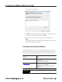
Install the Endress + Hauser Promag 53 Add-On Profile (AOP)
An AOP is a way to bring a definition of a new Allen-Bradley device or devices
from our Encompass partners into RSLogix 5000. These profiles will vary,
depending on the manufacturing and function of the target device. All contain
some configuration and automatic tag creation, so you do not have to figure
out how data is mapped or spend time creating aliases to point at the generic
tags.
This section describes how to install an AOP from Endress+Hauser for a
Promag 53 Flowmeter.
Note: The AOP is preinstalled in RSLogix 5000 versions 20 and higher.
1. Download the Promag 53 AOP from www.endress.com.
2. Double click the MPSetup.exe file from the download location.
The setup screen is displayed.
3. Click Next, and on subsequent screens, continue to follow the prompts,
accepting the default selections and clicking Next.
4. When a screen saying that the setup is complete is displayed, click
Finish.
The AOP is installed and available to add to the RSLogix 5000 Project,
as described in the following section.
Load the Electronic Data Sheet (EDS) File
Although the EDS file for this device is typically included in the installation of
the AOP, it is also available for you to install separately. If necessary, you can
access it from the device through the Webserver or the manufacturer’s website.
If you want to access the EDS
file from...
Then...
the device through the Webserver
1. Go to the Network Configuration screen (shown
on page 40).
2. Click the button Load EDS File.
www.endress.com
1. Download the EDS file.
2. Save the file to your desktop.
3. Double click the file and follow the on-screen
prompts.
IMPORTANT
Use the RSLinx EDS Hardware Installation Tool to install the EDS file.
Configure the E+H Promag
53 Flowmeter with the
AOP
The available options to configure the I/O in the AOP are presented in the
table on page 23. The option “Device Config. via AOP” described in the
procedure below is used as an example.
In the RSLogix 5000 project, ensure that the Ethernet Module(s) and
communication settings are established before installing the Promag 53. For
assistance with setting up Ethernet communications via the ControlLogix
Platform, refer to www.rockwell.com or ask the local Rockwell Automation
distributor.
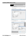
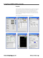
Establish the Configuration of the E+H AOP
1. On the left side of the RSLogix 5000 project screen, right click the
Ethernet Module, and then select New Module.
2. Choose Endress+Hauser under Module Type Vendor, select Promag_53
and then click Create.
IMPORTANT
Do not click OK in the New Module screen until you have completed
defining the module, as described in steps 3 through 5.
3. In the New Module screen:
a. Enter the necessary information in the Name and Ethernet Address
sections of the screen.
b. In the Module Definition section, click Change.
4. In the Module Definition screen:
a. Click the Connection drop-down list and select I/O Data (with config).
b. Click OK.
For more information about the available connections in the AOP, refer
to the table on the following page:
Available
Connections
in AOP
Device Config.
via AOP
(Recommended)
Device Config. via
Webserver
(Optional)
Device Config. via
Local Device
Display (Optional)
I/O Data
Not available
Yes
Yes
Input only
Not available
Yes
Yes
I/O Data
(with config.)*
Yes*
Not recommended*
Not recommended*
Input only
(with config.)*
Yes*
Not recommended*
Not recommended*
*If using the AOP for device configuration (I/O Data [with config.] or
Input only [with config.]), the configuration in the device is overwritten
with every Forward Open command.
IMPORTANT
Do not click OK in the Module Properties screen, until you ensure
that the module properties have the settings that you prefer.
5. If preferred, you can customize the Endress+Hauser Promag 53 AOP
properties using the tabs at the top of the Module Properties screen.
Tabs for
Customizing
AOP
Properties
• In the Connection screen, you can set the Requested Packet Interval
(RPI) and other communication parameters.
• In the Module Info screen, you can view the device information.
• In the User Interface screen, you can select the measurement values
on the local display for the device.
• In the System Units screen, you can configure the units of measure for
the system.
• In the System Parameters screen, you can configure the system
parameters, as shown below. .
• In the Totalizer (1...3) screen, you can assign the device totalizer
configuration and units.
• In the Process Parameters screen, you can configure process
parameters such as empty pipe and density calculations.
• In the Vendor screen, you can view vendor information.
6. When the module is defined according to your preferences, in the
Module Properties screen, click OK.
7. In the RSLogix 5000 warning screen, click Yes.
8. Ensure that you save the RSLogix 5000 file first, and then download the
file to the ControlLogix controller.
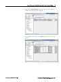
Available Data for the Promag 53
In RSLogix 5000, the Promag 53 has available data that is imported during
the EDS file installation. This data generated pre-configured Controller
Tags that are available to use for programming or monitoring/verification
of the device operation.
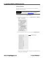
Perform the following steps to access the Controller Tags in RSLogix 5000.
1. Download the RSLogix Project, with the proper module configuration,
and change the controller to Run Mode.
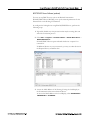
2. Right click on Controller Tags in the top of the Controller Organizer
window. The following screen will appear.
3. To expand the tag lists, click on the plus (+) signs to the left of the tag
names.
Visualization – Using
AOIs and Faceplates
To monitor the instruments using the predesigned faceplates, the EtherNet/IP
must be set up as specified in this integration document and the manual. The
controller exchanges data between the devices, and the FactoryTalk View SE
faceplates notify personnel what is happening in the plant.
The following information allows you to customize the Promag 53 and set up
the function blocks to use the Add-On Instructions (AOI) with an HMI
server.
See Additional Resources on page 47 for more detailed information.
Add-On Instructions
An Add-On Instruction exchanges data between each process variable located
in the process device and the faceplate installed on a display. The name of the
specific instance of the Add-On Instruction becomes the link from the actual
instrument to the faceplate on the graphic.
Global Object
A global object links the tag name to the faceplate, provides a touch area for
the faceplate to be launched from, and displays the process variables and
alarms.
IMPORTANT
A unique global object and faceplate are available for each field
instrument due to each instrument having specific extended
diagnostics.
Faceplates
The FactoryTalk View SE generic display provides a graphical representation
of the instrument based on the information contained within each Add-On
Instruction. Navigation buttons at the top of the faceplate change the
information displayed. Status displays show information using a bar graph,
numeric values, and trend displays. Other displays show specific alarms and
warning indications.
Some examples of predesigned faceplates are shown below.
IMPORTANT
A unique global object and faceplate are available for each field
instrument due to the display of instrument-specific extended
diagnostic information.
The faceplates provide the following information from the device:
Process values
PV fault status (communication fault)
Device extended status
You can configure the faceplates to provide the following information:
Tag name
Description
Engineering units
Mode (such as operator or program)
High-high, high, low, low-low alarms
Over-range and under-range alarms
Alarm delay
Alarm hysteresis
Configure the E+H
Promag 53 Flowmeter
(Optional Methods)
Optional methods for configuring the instrument, including the following:
• Quick setup menus on the local display
• Using the Webserver
Configure via Quick Setup Menus on Local Display (Optional)
On the local display of the field instrument, use the Quick Setup menus to
configure instrument parameters.
For additional information see Additional Resources on page 47.
Configure via Webserver (Optional)
Overview of the Webserver Menus
You can perform the following functions using the Webserver menus:
Menu
Description of Functions
Info
View the serial number of the device, Ethernet Hardware,
and communication status.
User Management
Assign access authorization to the Webserver.
Parameter Up-/Download
Save a configuration parameter from the device or
upload a configuration parameter to the device.
Ethernet Diagnostic
View the Ethernet diagnostics values.
Endress+Hauser
Access the Endress+Hauser homepage.
Overview
View information about the measuring device, the status,
and measured values.
Network Configuration
Configure the device network.
Data Map
View or edit the input and output values for EtherNet/IP
data transmission.
Device Config
View or configure the parameters of the measuring
device.
Firmware Update
Update the firmware of the dual Ethernet module.
Login
Enable access to the Webserver.
The following sections describe each menu in more detail.
Access the Webserver
Select Login to enable access to the Webserver.
The configuration when delivered is as follows:
• User: admin
• Password: admin
IMPORTANT
We recommend that you change the password for the administrator
after configuring the user rights with the User Management
Webserver menu, as described on page 38.
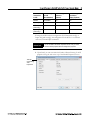
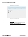
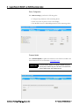
View an Overview of the Measuring Device
Select Overview to view information about the measuring device, the
measured values, and the current system condition of the measuring
device.
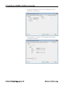
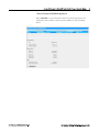
View Information
Select Info to view the serial number of the device, Ethernet hardware, and
communication status, as shown below.
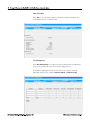
User Management
Select User Management to configure the access authorization for individual
users or user groups and assign the user name and password.
To enable the appropriate menus for the users or user groups, select the
individual categories, for example, Firmware Update or Network Config.
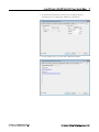
Upload or Download Configuration Parameters
Select Parameter Up-/Download to upload the configuration parameters from
the device or download configuration parameters to the device.
View Ethernet Diagnostic Values
Select Ethernet Diagnostic to view the Ethernet diagnostic values, as shown
below:
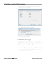
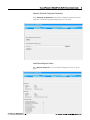
Network Configuration
Select Network Configuration to perform the following functions:
• Assign a tag name to the measuring device.
• Activate the DHCP client function for the EtherNet/IP network and
the Webserver.
• Configure the address, entering IP settings for the EtherNet/IP
network and the Webserver.
• Upload the device-specific EDS (Electronic Data Sheet) file for
integrating the measuring device into a network.
12
Data Map
View the Data Map
Select Data Map to view the input and output values for EtherNet/IP data
transmission and related information:
Position number
Description (1)
Register number
Current input and output values
Description (2)
Data type
Description (3)
The Data Map is subdivided as follows:
Positions 1 through 10 are input values sent by the measuring device to
the controller
Positions 11 through 16 are output values sent by the controller to the
measuring device.
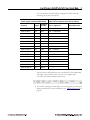
Configure the Data Map
The order and number of the input and output values can be adapted for
EtherNet/IP data transmission.
IMPORTANT
To configure the Data Map, write access to the related parameters
must be enabled. See Additional Resources on page 47.
1. In the Webserver, select the Device Config menu.
2. In the Device Configuration menu, select Basic Functions > Additional
Config. > Configuration.
3. Scroll through the list until you reach the parameter, SCAN LIST REG. 1.
SCAN LIST REG. 1
The parameters SCAN LIST REG. 1 through 16 correspond to Positions
1 through 16 in the Data Map.
12
For your reference, the Data Map is configured as follows when the
measuring device leaves the factory:
Parameter in Additional Settings
related register = position in the Data Map
Value Configuration When Delivered (an input or
output value is assigned to the position in question)
Parameter
Register
Position in
Data Map
Value = Register for
Input/Output Value
SCAN LIST REG. 1
5001
Row 1
2007
= Mass flow
Input values
SCAN LIST REG. 2
5002
Row 2
2009
= Volume flow
SCAN LIST REG. 3
5003
Row 3
–
SCAN LIST REG. 4
5004
Row 4
–
SCAN LIST REG. 5
5005
Row 5
–
SCAN LIST REG. 6
5006
Row 6
–
SCAN LIST REG. 7
5007
Row 7
2610
= Totalizer 1
SCAN LIST REG. 8
5008
Row 8
2810
= Totalizer 2
SCAN LIST REG. 9
5009
Row 9
3010
= Totalizer 3
SCAN LIST REG. 10
5010
Row 10
6859
= Actual system condition
SCAN LIST REG. 11
5011
Row 11
2608
= Reset totalizer 1
SCAN LIST REG. 12
5012
Row 12
2808
= Reset totalizer 2
SCAN LIST REG. 13
5013
Row 13
3006
= Reset totalizer 3
SCAN LIST REG. 14
5015
Row 14
0
=–
SCAN LIST REG. 15
5016
Row 15
0
=–
SCAN LIST REG. 16
5017
Row 16
0
=–
Output values
The mass flow is displayed in the first row (Position 1) in the Data Map.
This input value is the first value to be sent to the higher-order
controller via EtherNet/IP data transmission.
4. If you want to change the Data Map, you can configure it by entering the
Register and Value. For more information, see Additional Resources on
page 47.
Device Configuration
Select Device Config to perform the following tasks:
• Configure the parameters of the measuring device
• Show any system or process errors on the display
• Provide direct access to individual parameters of the measuring device
Firmware Update
Select Firmware Update to update the firmware for the Ethernet module. The
latest firmware file can be obtained at www.endress.com.
IMPORTANT
The device software (amplifier, I/O module) is updated through the
FXA193 service interface using the Flow Device FXA 193/291 DTM
and the FieldCare plant asset management tool.
12
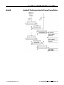
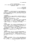
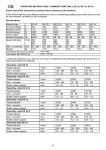
Appendix
View the IP Configuration Using the Promag 53 Local Display
>3s
E
+
-
Basic Functions
+
-
- +
E
Ethernet
+
-
E
Configuration
E
IP Address 1
Subnet Mask 1
Gateway 1
E
+
-
Supervision
E
IP Address 2
Subnet Mask 2
Gateway 2
+
-
Version-Info
+
-
E
Ethernet
E
E
SW-Rev. Sub A/E
MAC Add. 1
MAC Add. 2
Notes:
12
Additional Resources
Resource
Description
EtherNet/IP Field Instruments
Proline Promag 50W, 53W Technical Information, publication
T1046D/06/en
Specifications and details of the Promag 53E flowmeter
Proline Promag 53 Operating Instructions (Proline Promag 53
MODBUS RS485) publication BA117D
How to install, wire, configure, and operate a Promag 53
flowmeter
http://www.products.endress.com/ethernet-ip-eds
Download EDS and AOP files for field instrument
http://www.products.endress.com/flow
Information about Endress+Hauser flowmeters
Control System Components
ControlLogix Controllers Installation Instructions, publication
1756-IN101
How to install and configure a ControlLogix controller.
ControlLogix Controllers User Manual, publication 1756-UM001
How to configure, operate, and maintain a ControlLogix controller.
ControlLogix Ethernet/IP Modules 1756-IN612B-EN-P
Installation Instructions, ControlLogix EtherNet/IP Communication
Module
Operator Components
FactoryTalk View Site Edition User’s Guide, publication
VIEWSE-UM006
How to design, develop, and deploy FactoryTalk View SE
applications
Faceplates, Add-On Instructions, project files, etc.
http://rockwellautomation.com/knowledge base
(Login required. Please contact your sales representative.)
Download AOIs, Faceplates and Global Object graphics, and
project files
Process Control Information
Rockwell Automation Support
Rockwell Automation provides technical information on the Web to assist you in using its products. At
http://support.rockwellautomation.com, you can find technical manuals, a knowledge base of FAQs, technical and application
notes, sample code and links to software service packs, and a MySupport feature that you can customize to make the best use of
these tools.
For an additional level of technical phone support for installation, configuration, and troubleshooting, we offer TechConnect
support programs. For more information, contact your local distributor or Rockwell Automation representative, or visit
http://support.rockwellautomation.com.
Endress+Hauser Support
Please refer to your local Endress+Hauser Sales Center for precise information regarding the service support available in your area
or visit http://www.endress.com.
Installation Assistance
If you experience a problem within the first 24 hours of installation, please review the information that's contained in this manual.
You can also contact a special Customer Support number for initial help in getting your product up and running.
United States
1.440.646.3434
Monday – Friday, 8 a.m. – 5 p.m. EST
Outside United States
Please contact your local Rockwell Automation representative for any technical support issues.
New Product Satisfaction Return
Rockwell Automation tests all of its products to ensure that they are fully operational when shipped from the manufacturing
facility. However, if your product is not functioning and needs to be returned, follow these procedures.
United States
Contact your distributor. You must provide a Customer Support case number (call the phone
number above to obtain one) to your distributor in order to complete the return process.
Outside United States
Please contact your local Rockwell Automation representative for the return procedure.
Allen-Bradley, ControlLogix, FactoryTalk, Rockwell Automation, RSLinx, RSLogix 5000, and TechConnect are trademarks of Rockwell Automation, Inc.
Trademarks not belonging to Rockwell Automation are property of their respective companies.
E+H Publication SP00030A/04/en/01.12
Copyright © 2012 Endress+Hauser, Inc.
RA Publication PROCES-AP059B-EN-P – September 2012
Copyright © 2012 Rockwell Automation, Inc. All rights reserved. Printed in the U.S.A.