1
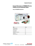
Integration Document
TMT 162 Temperature Transmitter
via FOUNDATION Fieldbus to the
PlantPAx Process Automation System
System Using a 1788-EN2FFR or CN2FFR
Topic
Page
Preferred Integration
2
Application Overview
4
TMT 162 Temperature Transmitter
6
Example System
11
Installation and Configuration
12
Visualization – Using AOIs and Faceplates
65
Additional Resources
70
2 iTEMP TMT 162 Temperature Transmitter via FOUNDATION Fieldbus to the PlantPAx Process Automation
System
Preferred Integration
Rockwell Automation and Endress+Hauser have strengthened their strategic
alliance to provide complete process automation solutions that use best-inclass instrumentation, software, and control systems.
There are hundreds of different components in a typical plant: controllers,
remote I/O, electrical drives, safety equipment, and sensors. Each must be
integrated, configured, and optimized during start-up and operation.
Recognizing the challenges this creates, Rockwell Automation and
Endress+Hauser are focused on providing you with scalable, off-the-shelf
solutions.
To supply robust system solutions, Rockwell Automation pre-tests many
third-party manufactured HART, FOUNDATION Fieldbus, and PROFIBUS
PA field devices in the system test laboratory for compatibility with the
Rockwell Automation PlantPAx process automation system. Each field device
is connected to the PlantPAx system and is subjected to interoperability testing
procedures similar to operating procedures in your plant. The results of each
field test are recorded in a test report for integration planning purposes.
For Endress+Hauser field devices, an additional step provides an “Integration
Document” and “Interoperability Statement” for each tested instrument. The
Integration Document provides information on installation, configuration,
startup, and operation of the integrated system. The Interoperability Statement
is assurance that the Endress+Hauser field device meets PlantPAx system
interoperability performance measures, as jointly established by Rockwell
Automation and Endress+Hauser and verified through completion of common
test procedures performed by either company. Both the Integration Document
and Interoperability Statement help reduce risk with ease of integration.
RA Publication PROCES-AP054B-EN-P – December 2012
E+H Publication SP00028A/04/en/02.13
iTEMP TMT 162 Temperature Transmitter via FOUNDATION Fieldbus to the PlantPAx Process Automation System
The overall mission of the alliance is to provide you with proven solutions that
combine field instrumentation with fieldbus networks, such as HART,
FOUNDATION Fieldbus, PROFIBUS PA and EtherNet/IP networks, with
asset management capabilities and Rockwell Automation’s system capabilities
to provide a total engineered solution.
Through preferred integration and support of increasing requirements for
plant-wide control, the alliance offers the following benefits:
•
•
•
•
•
Reduced integration costs throughout engineering,
commissioning, and start-up
Optimized plant availability and output
Ensured product quality and consistency
Optimized traceability to meet regulatory demands
Predictive maintenance through intelligent instruments
For new construction, process improvements at an existing plant, or operating
cost reductions, the alliance delivers the following:
•
•
•
E+H Publication SP00028A/04/en/02.13
Preferred integration reduces risk, reduces integration costs,
and protects investment with pre-engineered interoperability.
Both companies believe open systems and standardized
interfaces bring maximum benefits.
Advanced diagnostics with plant-wide control provides better
visibility of plant health and easier access to instrument
diagnostics, which ultimately leads to faster troubleshooting
and improves decision-making.
Collaborative lifecycle management leads to improvements in
design, engineering, and startup and support of plants. This
collaboration increases productivity, manages information
about instrumentation assets, optimizes plant assets, and
results in a complete lifecycle management solution.
RA Publication PROCES-AP054B-EN-P –December 2012
4 iTEMP TMT 162 Temperature Transmitter via FOUNDATION Fieldbus to the PlantPAx Process Automation
System
Application Overview
This document provides a step-by-step approach to integrating an
Endress+Hauser TMT 162 via FOUNDATION Fieldbus into a Rockwell
Automation PlantPAx process automation system.
This Section
Describes
Application Overview
Details about the field instrument and control system.
System Details
Specifications on the required hardware and software components.
Installation
How to install and connect the instrument, linking device and other components.
Configuration
How to:
•
•
Visualization
Configure the EN2FFR OR CN2FFR linking device.
Configure the measurement instrument.
How to implement and configure a graphical display of device information.
RA Publication PROCES-AP054B-EN-P – December 2012
E+H Publication SP00028A/04/en/02.13
iTEMP TMT 162 Temperature Transmitter via FOUNDATION Fieldbus to the PlantPAx Process Automation System
The ControlLogix platform provides a robust EtherNet/IP backbone for
communication to process fieldbus networks. The PlantPAx architecture uses
producer/consumer technology, allowing input information and output status
to be shared by all ControlLogix controllers in the system. This integration
document assumes you have a working knowledge of ControlLogix systems.
For more details regarding the equipment and tasks described in this
document see additional resources.
1788-EN2FFR EtherNet/IP Network
The diagram above is an example of an EtherNet/IP network.
This integration document assumes you have a working knowledge of
ControlLogix systems. For more details regarding the equipment and
tasks described in this document, see Additional Resources.
E+H Publication SP00028A/04/en/02.13
RA Publication PROCES-AP054B-EN-P –December 2012
6 iTEMP TMT 162 Temperature Transmitter via FOUNDATION Fieldbus to the PlantPAx Process Automation
System
TMT 162 Temperature
Transmitter
The iTEMP temperature field transmitter TMT162 is a two-wire transmitter with analog
output or Fieldbus protocol, two (optional) measuring inputs for resistance thermometers
and resistance transmitters in 2-wire, 3-wire or 4-wire connection, thermocouples and voltage
transmitters. The LC display shows the current measured value digitally and as a bar graph
with an indicator for alarms. The unit is designed for mounting in the field.
Features and benefits:
•
•
•
•
•
•
•
•
RA Publication PROCES-AP054B-EN-P – December 2012
Highest reliability in harsh industrial environments due to dual
compartment housing and compact fully potted electronics
Blue backlit display with large measured value, bar graph and fault
condition indication for ease of reading
Ability to display parameters of up to four other devices
Dual sensor input capability e.g. 2 Pt100 3-wire or 1 Pt100 4-wire &
TC
Min./max. process value recorded
Sensor monitoring: Breakdown information, sensor backup, drift
alarm and corrosion detection avoids shutdown and enables a quick
maintenance intervention
Sensor matching: Linearization with Callendar van Dusen or
polynomial - equation allowing for optimal accuracy of the
temperature measurement
Mathematical functions for differential and average temperature
add flexibility to the measurement
E+H Publication SP00028A/04/en/02.13
iTEMP TMT 162 Temperature Transmitter via FOUNDATION Fieldbus to the PlantPAx Process Automation System
Corrosion of the sensor connections can lead to corruption of the measured value. The field
transmitter therefore offers the option of detecting corrosion on the thermocouples and
resistance thermometers with a 4-wire connection before measured value corruption occurs.
The transmitter avoids false measured readings and is also able to indicate a warning on the
display as well as through HART or FOUNDATION Fieldbus protocol when wire
resistance are exceeding reasonable values.
E+H Publication SP00028A/04/en/02.13
RA Publication PROCES-AP054B-EN-P –December 2012
iTEMP TMT 162 Temperature Transmitter via FOUNDATION Fieldbus to the PlantPAx Process Automation System
Measured Variables
Temperature (temperature linear transmission behavior), resistance and voltage.
Signals from Instruments to Control System
FOUNDATION Fieldbus Interface:
•
•
•
•
•
•
•
•
FOUNDATION fieldbus H1, IEC 61158-2, galvanically isolated
Data transmission rate: 31.25 kBit/s
Current consumption: ≤11 mA
Permitted supply voltage: 9 to 32 V
Error current FDE (Fault Disconnection Electronic): 0 mA
Bus connection with integrated reverse polarity protection
Signal encoding: Manchester II
Link Master (LM) function is supported
See Additional Resources for complete protocol specific data.
RA Publication PROCES-AP054B-EN-P – December 2012
E+H Publication SP00028A/04/en/02.13
iTEMP TMT 162 Temperature Transmitter via FOUNDATION Fieldbus to the PlantPAx Process Automation System
Control System
The control system includes these components:
Component
Description
Controller
The ControlLogix controller is a modular, high performance control that uses RSLogix 5000
programming software to configure, program, and monitor a system.
FOUNDATION Fieldbus
linking device
The 1788-EN2FFR linking device provides a gateway between EtherNet/IP and a single
segment FOUNDATION Fieldbus H1 layer.
The 1788-CN2FFR linking device provides a gateway between ControlNet and FOUNDATION
fieldbus (FF). Hereafter, both modules are referred to as the linking device.
The linking device can support 16 field devices and is configurable through RSLogix™ 5000 by
a dedicated add-on-profile (AOP). Multiple levels of media redundancy are supported, including
ring, split, and redundant trunk, plus options for H1 media, redundant linking devices,
redundant controllers, and ControlNet.
The linking device has full FOUNDATION fieldbus host capability, including link active
scheduler (LAS) capability.
Programming software
PlantPAx is an easy object-oriented, explorer-based, drag-and-drop configuration that allows
you to build complex process functions. Furthermore, the software allows you to mix and
match IEC61131-3 compliant programming languages. All supported programming languages
share the same development environment, tag database, and user interface, resulting in
reduced training and higher productivity.
Visualization software
FactoryTalk® View Site Edition software is HMI software program for monitoring, controlling,
and acquiring data from manufacturing operations throughout an enterprise. A generic display
provides a graphical representation via faceplates of the field instrument connected to the
EN2FFR linking device.
E+H Publication SP00028A/04/en/02.13
RA Publication PROCES-AP054B-EN-P – December 2012
iTEMP TMT 162 Temperature Transmitter via FOUNDATION Fieldbus to the PlantPAx Process Automation System
Asset management
software
FactoryTalk AssetCentre, with a fully scalable design, provides a set of asset-centric
focused tools for securely and centrally managing factory and process automation
production environments. It secures access to the control system, tracks users' actions,
managing asset configuration files, configuring process instruments, and provides
backup and recovery of operating asset configurations.
• Change management — management of security, configuration and archiving of
control assets.
• Process device management — calibration and configuration for process
instrumentation.
• Condition monitoring — predict or prevent impending failures of process
instrumentation with centralized device information.
• Disaster recovery — for all assets and devices.
FactoryTalk AssetCentre is based on the open, industry-leading FDT/DTM technology
integrated into the PlantPAx process automation system. It is a common environment
and launch application for Device Type Manager (DTM). An expanding library of Device
DTMs and an array of Communication DTMs are supported.
The optional smart device configuration tool, FieldCare, and the Life Cycle
Management tool W@M are Endress+Hauser’s plant asset management solution.
• Easy to implement and to scale up into existing infrastructure.
• Entire management of smart field devices supporting EtherNet, HART,
PROFIBUS, FOUNDATION Fieldbus and Wireless HART.
• Supports the entire device life cycle based on W@M starting with
engineering through ordering, installation, configuration, commissioning,
calibration, documentation management and spare parts handling.
• Endures technology migration by supporting all device DTMs and iDTMs for
DD based devices.
• Allows communication through third party systems supporting FDT/DTM
technology.
• Condition monitoring: used for preventive and predictive maintenance based
on diagnostic information from field devices.
FieldCare suite enables you to step into the asset management world with a sustainable
investment and offers the possibility to scale up to an integrated asset management
solution
RA Publication PROCES-AP054B-EN-P – December 2012
E+H Publication SP00028A/04/en/02.13
iTEMP TMT 162 Temperature Transmitter via FOUNDATION Fieldbus to the PlantPAx Process Automation System
Example System
Endress+Hauser and Rockwell Automation interoperability testing is
performed for every new device and product.
Hardware Components
Component
Catalog Number
E+H TMT162 Temperature Transmitter
TMT162-A2C131KAB
Hiprom FOUNDATION Fieldbus
1788-EN2FFR
Communications Module or
Hiprom ControlNet Communications Module 1788-CN2FFR
Allen-Bradley Stratix 8000 Switch
1783-MS10T
Allen-Bradley Power Supply
1606-XLE
Allen-Bradley ControlLogix Control System
1756-L7X
Allen-Bradley EtherNet Bridge
1756-EN2TR
Hiprom FOUNDATION Fieldbus Termination
FBJ-B6
For further details, see the PlantPAx Process Automation System Selection
Guide, publication PROCES-SG001-EN-P.
Software Components
Component
Catalog Number
PlantPAx
RSLogix 5000 Enterprise Series
programming software, Professional
edition
9324-RLD700NXENE
Includes:
• RSLinx Classic software
• RSLinx Enterprise software
FactoryTalk View Site Edition (SE) software
(optional)
FactoryTalk AssetCentre server
FactoryTalk AssetCentre process
device configuration
E+H FieldCare Standard Asset
Management software (optional)
9701-VWSXXXXXENE
9515-ASTSRVRENE
9515-ASTPRDCFENE
SFE500
For specifications of the engineering workstation (EWS) and operator
workstation (OWS), see theIntegrated Architecture for Process Control System
Recommendations Manual, publication PROCES-RM001.
See Additional Resources for complete installation instructions, including
warnings.
E+H Publication SP00028A/04/en/02.13
RA Publication PROCES-AP054B-EN-P – December 2012
iTEMP TMT 162 Temperature Transmitter via FOUNDATION Fieldbus to the PlantPAx Process Automation System
Installation and
Configuration
The following information is a summary of the installation procedures. See
Additional Resources for complete installation instructions, including
warnings.
Connect an iTEMP TMT 162 Temperature Transmitter
Note:
• Switch off power supply before installing or connecting the device.
Failure to observe this may result in destruction of parts of the
electronics.
•
When installing Ex-approved devices in a hazardous area please take
special note of the instructions and connection schematics in the
respective Ex documentation added to these Operating Instructions.
The local E+H representative is available for assistance if required.
1. Remove the cover clamp.
2. Unscrew the housing cover on the connection compartment together with
the O-ring.
RA Publication PROCES-AP054B-EN-P – December 2012
E+H Publication SP00028A/04/en/02.13
iTEMP TMT 162 Temperature Transmitter via FOUNDATION Fieldbus to the PlantPAx Process Automation System
3. Open the cable glands of the device.
4. Feed the cables through the opening in the cable glands.
5. Connect the cables.
6. On completion of wiring, screw the screw terminals tight. Tighten the
cable glands again. Screw the housing cover down again and refit the cover
clamp.
Note: Supply voltage must match the voltage noted on the nameplate.
Item
Description
A
FF terminals – fieldbus communication and power supply
B
Fieldbus cable (FOUNDATION Fieldbus)
C
Ground terminals
D
Ground terminal (external, relevant for remote version)
Verify Grounding and Shielding
TMT 162 must be grounded, for example by means of the external earth
terminal.
Different grounding and screening installation methods are available for
FOUNDATION Fieldbus networks such as:
•
•
•
E+H Publication SP00028A/04/en/02.13
Isolated installation (see also IEC 61158-2)
Installation with multiple grounding
Capacitive installation
RA Publication PROCES-AP054B-EN-P – December 2012
iTEMP TMT 162 Temperature Transmitter via FOUNDATION Fieldbus to the PlantPAx Process Automation System
Fieldbus Connector
The connection technology of FOUNDATION Fieldbus allows measuring
devices to be connected to the fieldbus via uniform mechanical connections,
such as T-boxes, distribution modules, etc. This connection technology, which
uses prefabricated distribution modules and plug-in connectors, offers
substantial advantages over conventional wiring.
•
•
•
Field devices can be removed, replaced or added at any time during
normal operation. Communication is not interrupted.
Installation and maintenance are significantly easier.
Existing cable infrastructures can be used and expanded instantly, e.g.
when constructing new star distributors using 4-channel or 8-channel
distribution modules.
The device can therefore be supplied with a ready-mounted fieldbus
connector. Fieldbus connectors for retrofitting can be ordered from
Endress+Hauser as a spare part. Please see Endress+Hauser Support and
contact your representative.
Item
Description
A
Protection cap for connector
B
Fieldbus connector
Pin assignment/color codes
1
Brown wire: FF+ (terminal 1)
2
Blue wire: FF- (terminal 2)
3
Not assigned
4
Green/yellow: earth
Note: Protect the terminals from electric discharge. Failure to observe this
may result in destruction of parts of the electronics.
RA Publication PROCES-AP054B-EN-P – December 2012
E+H Publication SP00028A/04/en/02.13
iTEMP TMT 162 Temperature Transmitter via FOUNDATION Fieldbus to the PlantPAx Process Automation System
Hiprom Linking Device Overview
The following section demonstrates installation of both the EN2FFR and the
CN2FFR. Programming and other setup instructions contained in the remaining
sections of this manual are consistent with either linking device. Refer to the
figures in this section when using the installation instructions.
Connect a Field Instrument to EN2FFR
The 1788-EN2FFR linking device is designed to operate within the Rockwell
Automation PlantPAx system using EtherNet/IP as the communication
backbone to the FOUNDATION Fieldbus process device network. All power
required for the module’s operation is derived from an external 24V power
supply. For current consumption, please refer to electrical specifications in the
EN2FFR user manual.
The following installation can be accomplished by either traditional methods
or by utilizing fieldbus connectors (optional). In this section, both methods are
described to allow you to choose the installation method best suited to the
application.
E+H Publication SP00028A/04/en/02.13
RA Publication PROCES-AP054B-EN-P – December 2012
iTEMP TMT 162 Temperature Transmitter via FOUNDATION Fieldbus to the PlantPAx Process Automation System
Hardware
ATTENTION: Do not wire more than one conductor on any single terminal.
Power Connection
The power supply must be compliant with CE safety extra low voltage (SELV)
or protected extra low voltage (PELV), and UL Class 2 or limited
voltage/current requirements.
We recommend a 24-32V DC power supply for the linking device to operate
correctly. No additional power supplies or power conditioners are required.
The power supply connection is described here.
IMPORTANT
Do not use additional power supplies or power conditioners
with the 1788-EN2FFR and 1788-CN2FFR linking devices.
RA Publication PROCES-AP054B-EN-P – December 2012
E+H Publication SP00028A/04/en/02.13
iTEMP TMT 162 Temperature Transmitter via FOUNDATION Fieldbus to the PlantPAx Process Automation System
H1 Network Connections
The H1 network must be connected via the
H1 terminal on the linking device. The H1
network connection and pin-out is described
here.
Pin
Description
Right/Top (red)
FF +
Middle (green)
FF -
Left/Bottom
Shield
The H1 Segment is split between two
physical ports, A and B.
E+H Publication SP00028A/04/en/02.13
RA Publication PROCES-AP054B-EN-P – December 2012
iTEMP TMT 162 Temperature Transmitter via FOUNDATION Fieldbus to the PlantPAx Process Automation System
ControlNet and EtherNet/IP Connections
Two BNC connectors on the base of the 1788-CN2FFR linking device
provide connections for single or dual ControlNet media. The dual port
EtherNet/IP switch provides connections for multiple EtherNet topologies,
including Device Level Ring (DLR). The EtherNet/IP port can also be used as
a connection point in the field to access the Web server or asset management
tools.
The ControlNet connections are described here.
Shielding
Ground the linking device shield connection to a clean earth
connection. Connect the shield to the H1 media so that connectivity
runs through all junction boxes, but is not connected to the field device
shield or grounded at the device.
Do not attach the H1 media shield to the field device. Tape the media shield
back to avoid accidental contact with other conductors or ground.
RA Publication PROCES-AP054B-EN-P – December 2012
E+H Publication SP00028A/04/en/02.13
iTEMP TMT 162 Temperature Transmitter via FOUNDATION Fieldbus to the PlantPAx Process Automation System
Set the Linking Device Network Address
This section describes the network address switches.
Hardware Switches Location
The hardware switches are located under the front cover of the linking
device. Use the Page button to toggle between different diagnostics on the
display.
E+H Publication SP00028A/04/en/02.13
RA Publication PROCES-AP054B-EN-P – December 2012
iTEMP TMT 162 Temperature Transmitter via FOUNDATION Fieldbus to the PlantPAx Process Automation System
Set the ControlNet Node Address
To set the ControlNet node address of the 1788-CN2FFR linking device, use
the hardware switches behind the front cover.
RA Publication PROCES-AP054B-EN-P – December 2012
E+H Publication SP00028A/04/en/02.13
iTEMP TMT 162 Temperature Transmitter via FOUNDATION Fieldbus to the PlantPAx Process Automation System
Set the EtherNet/IP Address
The linking device uses an RJ45 connector to connect to an Ethernet
network. The linking device ships with BOOTP enabled. To set the IP
address of the 1788-EN2FFR linking device, use a BOOTP server or use
the hardware switches.
IMPORTANT
Power down the linking device before changing the Ethernet switch
settings. The IP address is set during power up.
E+H Publication SP00028A/04/en/02.13
RA Publication PROCES-AP054B-EN-P – December 2012
iTEMP TMT 162 Temperature Transmitter via FOUNDATION Fieldbus to the PlantPAx Process Automation System
Ethernet Switch Settings
This table describes the Ethernet switch settings.
Ethernet Switch
Setting
Description
To set the IP address of the linking device to the 192.168.1.xxx
sub net, set the switches to the required last three digits.
In this example, the linking device will start up with IP address:
192.168.1.123.
To set the IP address of the linking device via a BOOTP server, set
the switches to
888 (factory default setting).
Power up the linking device and set the IP address using any
BOOTP server.
Once the new IP address has been set, power down the linking
device, return the switches to 000, and power up the linking
device.
Normal setting after setting IP address with BOOTP.
The 000 setting disables BOOTP and holds the IP address.
The linking device has the option to run the firmware that it was
originally shipped with.
If the power was cycled while upgrading the firmware, the
linking device may not start up because the firmware was
corrupted.
Set the switches to 777 to set the linking device into Safe mode
and upgrade the firmware again.
RA Publication PROCES-AP054B-EN-P – December 2012
E+H Publication SP00028A/04/en/02.13
iTEMP TMT 162 Temperature Transmitter via FOUNDATION Fieldbus to the PlantPAx Process Automation System
Install the TMT 162 Add On Profile (AOP)
You need the AOP for RSLogix 5000 to configure
and manage the linking device.
The installation of the AOP includes the
HSProcessUtility that is used to manage DTMs
and DD service libraries. See Additional
Resources.
The AOP install file is available on the
accompanying CD, or you can download the file
from the product website www.hiprom.com.
Go to the page for your linking device and click
the link for the AOP Setup software on the right
side of the page (1788-EN2FFR linking device
shown).
AOP Version
The AOP version of the linking device is located on the display during the
startup process, or via the web server.
TIP: You can also click the upper-left corner of the profile window and click
About Module Profile to view the AOP version.
E+H Publication SP00028A/04/en/02.13
RA Publication PROCES-AP054B-EN-P – December 2012
iTEMP TMT 162 Temperature Transmitter via FOUNDATION Fieldbus to the PlantPAx Process Automation System
Install the Device Type Manager Files (DTMs)
To install the Hiprom AOP and DTM, go to the Hiprom site and download
the files. Open the files, one at a time and follow the onscreen prompts. Wait
until you are finished installing the first file before installing the next.
To install the TMT 162 DTM, go to the Endress+Hauser website and
download the file. Open and install by following the onscreen prompts.
Firmware Version
The firmware version is printed on the linking device and displayed on the
screen during power up. The web server also provides the firmware version.
Load the Electronic Data Sheet (EDS) File
Although the EDS file for this device is typically included in the installation of
the AOP, it is also available for you to install separately. If necessary, you can
access it from the device through the Webserver or the manufacturer’s website.
IMPORTANT
Use the RSLinx EDS Hardware Installation Tool to install the EDS
file.
RA Publication PROCES-AP054B-EN-P – December 2012
E+H Publication SP00028A/04/en/02.13
iTEMP TMT 162 Temperature Transmitter via FOUNDATION Fieldbus to the PlantPAx Process Automation System
Configure in RSLogix 5000
The steps necessary to setup and configure the EN2FFR and TMT 162 in
RSLogix 5000 are presented on the following pages.
In the RSLogix 5000 project, ensure that the Ethernet Module(s) and
communication is established before proceeding with installation of the
EN2FFR and TMT 162.
Using RSWho Active, verify the recognized devices and communications.
The Controller, Bridge, and Linking Devices must be added to the I/O tree of the
ControlLogix Controller in RSLogix 5000 before the user can configure the devices.
For assistance with setting up Ethernet communications via the
ControlLogix Platform, refer to www.rockwell.com or ask the local
Rockwell Automation distributor.
E+H Publication SP00028A/04/en/02.13
RA Publication PROCES-AP054B-EN-P – December 2012
iTEMP TMT 162 Temperature Transmitter via FOUNDATION Fieldbus to the PlantPAx Process Automation System
IMPORTANT For this example, use I/O configuration utility to select module and
Add IP address for the 1756-EN2T to 192.168.1.8 and 192.168.1.17
for the Linking Device. Your addressing may be different.
1. Open RSLogix 5000 and select File.
2. Click New.
3. The New Controller window will appear.
RA Publication PROCES-AP054B-EN-P – December 2012
E+H Publication SP00028A/04/en/02.13
iTEMP TMT 162 Temperature Transmitter via FOUNDATION Fieldbus to the PlantPAx Process Automation System
4. Select the Type of controller,
revision, and fill in the remaining
fields with the appropriate
information for the available
equipment. Click OK. The
controller you just configured
will now be in the tree on the left
of the RSLogix 5000 window.
5. Right click on 1756 Backplane, and click on New Module. The Select
New Module Type screen will appear.
6. Add the module 1756-EN2T by selecting it from the list. Then click
Create.
E+H Publication SP00028A/04/en/02.13
RA Publication PROCES-AP054B-EN-P – December 2012
iTEMP TMT 162 Temperature Transmitter via FOUNDATION Fieldbus to the PlantPAx Process Automation System
7. In the New Module window, enter the EtherNet address 192.168.1.8
and fill in the remaining fields.
8. Click OK. The new device window will now be in the I/O tree.
RA Publication PROCES-AP054B-EN-P – December 2012
E+H Publication SP00028A/04/en/02.13
iTEMP TMT 162 Temperature Transmitter via FOUNDATION Fieldbus to the PlantPAx Process Automation System
9. Rick click on the EtherNet
symbol just below the newly
added EN2T. Click New
Module.
10. Select EN2FFR, then click Create.
E+H Publication SP00028A/04/en/02.13
RA Publication PROCES-AP054B-EN-P – December 2012
iTEMP TMT 162 Temperature Transmitter via FOUNDATION Fieldbus to the PlantPAx Process Automation System
11. Fill in the fields including the EtherNet address of 192.168.1.17 and click
OK.
12. The I/O tree should resemble this.
RA Publication PROCES-AP054B-EN-P – December 2012
E+H Publication SP00028A/04/en/02.13
iTEMP TMT 162 Temperature Transmitter via FOUNDATION Fieldbus to the PlantPAx Process Automation System
13. Go online with RSLogix 5000 by opening the Communication menu at
the top of the screen and select Who Active. The following window will
appear.
14. Expand the tree to find the ControlLogix controller by clicking the plus
sign to the left of the EN2T EtherNet module, as well as the Backplane.
Select the processor from the tree. In this case it is number 1756-L75.
Then click Download
E+H Publication SP00028A/04/en/02.13
RA Publication PROCES-AP054B-EN-P – December 2012
iTEMP TMT 162 Temperature Transmitter via FOUNDATION Fieldbus to the PlantPAx Process Automation System
15. Click Download when the following screen appears.
16. Click Yes when the download is finished.
After the modules are added to the I/O tree, the user can open the module
properties by right clicking the device and selecting Properties from the popup menu. In the properties window, select the Configuration tab to configure
addition settings.
RA Publication PROCES-AP054B-EN-P – December 2012
E+H Publication SP00028A/04/en/02.13
iTEMP TMT 162 Temperature Transmitter via FOUNDATION Fieldbus to the PlantPAx Process Automation System
17. On the I/O tree, right click on the EN2FFR and click Properties. The
module properties will appear as below. Select the Configuration tab.
18. Select Master, then Config from the tree on the left.
E+H Publication SP00028A/04/en/02.13
RA Publication PROCES-AP054B-EN-P – December 2012
iTEMP TMT 162 Temperature Transmitter via FOUNDATION Fieldbus to the PlantPAx Process Automation System
19. Verify the “Online” status in the upper left corner of the window.
IMPORTANT
Device Description files are normally included in the installation of
the AOP. The following steps, 20- 23, are only necessary if you
need to download the DD (Device Description) file. If not, proceed
with the next section, “TMT 162” Configuration in RSLogix 5000.
20. From the Configuration tab in the EN2FFR Properties window, click on
the Process Catalog button near the top of the window.
RA Publication PROCES-AP054B-EN-P – December 2012
E+H Publication SP00028A/04/en/02.13
iTEMP TMT 162 Temperature Transmitter via FOUNDATION Fieldbus to the PlantPAx Process Automation System
21. Select Launch Process Utility from the menu.
22. From the HS Process Utility select FOUNDATION Fieldbus and select
Add Device Description.
23. Select the DD files that you wish to install from the list.
E+H Publication SP00028A/04/en/02.13
RA Publication PROCES-AP054B-EN-P – December 2012
iTEMP TMT 162 Temperature Transmitter via FOUNDATION Fieldbus to the PlantPAx Process Automation System
TMT 162 Configuration in RSLogix 5000
The following steps allow the user to configure, download, and verify available
data for the TMT 162 Temperature Transmitter.
1. Right click on the TMT 162 device and select Auto Configure Online.
2. Go online by clicking the Double Green Arrows button on the left of the
screen.
RA Publication PROCES-AP054B-EN-P – December 2012
E+H Publication SP00028A/04/en/02.13
iTEMP TMT 162 Temperature Transmitter via FOUNDATION Fieldbus to the PlantPAx Process Automation System
3. Click Yes on the following warning screen (if it appears) if you are sure
you wish to change the device revision in the project.
4. Download the configuration to the TMT 162 by clicking the Large Green
Arrow button.
You should see a progress bar as below.
E+H Publication SP00028A/04/en/02.13
RA Publication PROCES-AP054B-EN-P – December 2012
iTEMP TMT 162 Temperature Transmitter via FOUNDATION Fieldbus to the PlantPAx Process Automation System
5. When the download is complete, click OK.
6. To verify the device configuration and revision information, right click on
the Resource Block and select Parameters.
RA Publication PROCES-AP054B-EN-P – December 2012
E+H Publication SP00028A/04/en/02.13
iTEMP TMT 162 Temperature Transmitter via FOUNDATION Fieldbus to the PlantPAx Process Automation System
7. Select parameters that you wish to enable by checking the boxes on the
left.
The following steps will demonstrate setup of the analog parameters for the
TMT 162.
8. Right click on the Process Variable and select Attributes.
E+H Publication SP00028A/04/en/02.13
RA Publication PROCES-AP054B-EN-P – December 2012
iTEMP TMT 162 Temperature Transmitter via FOUNDATION Fieldbus to the PlantPAx Process Automation System
9. Save by clicking the Disk button.
10. Click Exit to return to the configuration screen. The TMT 162 will be
available on the RSLogix I/O tree.
RA Publication PROCES-AP054B-EN-P – December 2012
E+H Publication SP00028A/04/en/02.13
iTEMP TMT 162 Temperature Transmitter via FOUNDATION Fieldbus to the PlantPAx Process Automation System
11. Expand the TMT 162 tree by clicking the plus sign.
12. Click on the attributes below the TMT 162 in the tree to view available data
about the device. Screen examples are shown below.
E+H Publication SP00028A/04/en/02.13
RA Publication PROCES-AP054B-EN-P – December 2012
iTEMP TMT 162 Temperature Transmitter via FOUNDATION Fieldbus to the PlantPAx Process Automation System
13. When finished viewing the device data, click OK to close the window.
IMPORTANT
Remember to save the RSLogix 5000 project to avoid losing the changes!
Alternate Installation using the Thin Frame
In most cases, DTM files are included with the installation of the AOP and can
be used in the Thin Frame included in RSLogix 5000 or with a FDT Frame
(such as AssetCentre or FieldCare). There may be an instance where the user
may need to install or re-install one or more DTMs. This section of the manual
will walk you through the installation process using RSLogix 5000.
IMPORTANT
The Thin Frame can only view diagnostics of the field device. A full
FDT Frame is needed to configure and parameterize the field device.
In order to use RSLogix 5000 to install DTMs, the user must update the DTM
catalog by launching the Process Utility in the EN2FFR module properties
window, configuration tab.
1. Right click on Process Catalog and select Launch Process Utility.
RA Publication PROCES-AP054B-EN-P – December 2012
E+H Publication SP00028A/04/en/02.13
iTEMP TMT 162 Temperature Transmitter via FOUNDATION Fieldbus to the PlantPAx Process Automation System
2. So that the DTM library is updated with all available DTMs, click DTM
and Update Catalog on the utility screen.
3. After the update is finished, click DTM and select DTM Viewer from the
menu.
IMPORTANT
Multiple DTMs for the same device with different revisions may be
available. The user must select the correct revision for the specified
device.
4. Select the DTM that you need from the list and click the Launch DTM
button.
E+H Publication SP00028A/04/en/02.13
RA Publication PROCES-AP054B-EN-P – December 2012
iTEMP TMT 162 Temperature Transmitter via FOUNDATION Fieldbus to the PlantPAx Process Automation System
5. Or select the Advance attribute on the EN2FFR properties configuration
tab to find and open the DTM.
6. Use the DTM to go online buy selecting the Online button below.
7. After the DTM goes online with the device, the following screen will
appear.
8. Save the project.
RA Publication PROCES-AP054B-EN-P – December 2012
E+H Publication SP00028A/04/en/02.13
iTEMP TMT 162 Temperature Transmitter via FOUNDATION Fieldbus to the PlantPAx Process Automation System
Verify Operation Using RSLogix 5000
Each 1788-EN2FFR consumes a total of 4 connections from the Logix
Controller regardless of the number of field devices. Thus the input and
output image of each EN2FFR is divided into four sections A to D. The first
connection will have the FF Master Data.
The following section will show the user how to use the AOP to monitor
online data.
1. In the RSLogix 5000 tree, select Controller Tags. Then select
EN2FFR:IA, then Master.
If a field device is online and running (exchanging cyclic data) then its field
device index bit (in the connection status) will be set. If the device goes offline,
the bit will be cleared.
2. Select the plus sign next to Field Device 00 and click to expand Data.
Each field device will display its diagnostics as well as all available PVs and
their status as shown below.
E+H Publication SP00028A/04/en/02.13
RA Publication PROCES-AP054B-EN-P – December 2012
iTEMP TMT 162 Temperature Transmitter via FOUNDATION Fieldbus to the PlantPAx Process Automation System
Configure via AssetCentre
Rockwell’s AssetCenter is the FDT based plant asset management software
tool that lets you configure the intelligent field instruments for
Endress+Hauser. FieldCare is an optional tool provided by Endress+Hauser.
IMPORTANT
Before beginning this process, make sure the DTMs have been
downloaded from the vendor website, imported, and installed for
both the Hiprom EN2FFR and the E+H device.
1. After installing the appropriate DTM files, start AssetCenter using the icon
on the desktop and open a new project.
2. Update the DTM catalog in AssetCenter by clicking on Tools, then DTM
Catalog.
3. Click Scan Now to verify that the DTMs you installed exist in the catalog.
RA Publication PROCES-AP054B-EN-P – December 2012
E+H Publication SP00028A/04/en/02.13
iTEMP TMT 162 Temperature Transmitter via FOUNDATION Fieldbus to the PlantPAx Process Automation System
4. Close the DTM catalog and setup the DTM network path. Click the
Tasks menu, then click DTM Networks.
5. Click on the name of the DTM network on the tree to the left, then click
Add DTM.
E+H Publication SP00028A/04/en/02.13
RA Publication PROCES-AP054B-EN-P – December 2012
iTEMP TMT 162 Temperature Transmitter via FOUNDATION Fieldbus to the PlantPAx Process Automation System
6. Select the DTM network and click on it to view the device DTM
information on the bottom of the screen.
7. Select the 1788-EN2FFR and click OK to add the communications DTM.
RA Publication PROCES-AP054B-EN-P – December 2012
E+H Publication SP00028A/04/en/02.13
iTEMP TMT 162 Temperature Transmitter via FOUNDATION Fieldbus to the PlantPAx Process Automation System
8. Add the IP address and Max Scan Address (the highest IP address used on
the network) and hit the Enter key after each field is filled.
9. After you click Next on the above screen, the tree should look like this one.
E+H Publication SP00028A/04/en/02.13
RA Publication PROCES-AP054B-EN-P – December 2012
iTEMP TMT 162 Temperature Transmitter via FOUNDATION Fieldbus to the PlantPAx Process Automation System
10. Right click on the device and select Online from the menu.
11. Right click on the EN2FFR, then Add DTM.
RA Publication PROCES-AP054B-EN-P – December 2012
E+H Publication SP00028A/04/en/02.13
iTEMP TMT 162 Temperature Transmitter via FOUNDATION Fieldbus to the PlantPAx Process Automation System
12. Select the correct DTM, and then click OK.
13. Fill in the node address field, then hit the Enter key.
E+H Publication SP00028A/04/en/02.13
RA Publication PROCES-AP054B-EN-P – December 2012
iTEMP TMT 162 Temperature Transmitter via FOUNDATION Fieldbus to the PlantPAx Process Automation System
IMPORTANT
Right click the devices in the tree to verify online status.
14. The device tree should resemble the one below.
15. Select the TMT 162 and click Open. Verify the device is connected by
looking at the bottom left corner of the screen. Then click Next.
IMPORTANT
RA Publication PROCES-AP054B-EN-P – December 2012
Use the tree on the left of the DTM frame to navigate to different
properties of the device, make changes, or view data.
E+H Publication SP00028A/04/en/02.13
iTEMP TMT 162 Temperature Transmitter via FOUNDATION Fieldbus to the PlantPAx Process Automation System
16. To get information about the DTM, click DTM Information.
An information screen will display the DTM details.
17. Click Close to finish, then Save the project to ensure that the changes are
not lost.
E+H Publication SP00028A/04/en/02.13
RA Publication PROCES-AP054B-EN-P – December 2012
iTEMP TMT 162 Temperature Transmitter via FOUNDATION Fieldbus to the PlantPAx Process Automation System
The remaining steps will verify that the DTM is installed and working properly
in AssetCenter.
18. First click the Design button above the tree to enter Design mode. Then,
in the AssetCenter tree, right click Process Area and select New.
19. From the Process Area Tree in the Asset Type to Add window, click
Instrument then OK.
RA Publication PROCES-AP054B-EN-P – December 2012
E+H Publication SP00028A/04/en/02.13
iTEMP TMT 162 Temperature Transmitter via FOUNDATION Fieldbus to the PlantPAx Process Automation System
20. Enter a name (i.e. – Instrument) in the Name field. Click OK.
21. Right click on the newly named device and select Properties from the
menu.
E+H Publication SP00028A/04/en/02.13
RA Publication PROCES-AP054B-EN-P – December 2012
iTEMP TMT 162 Temperature Transmitter via FOUNDATION Fieldbus to the PlantPAx Process Automation System
22. Select DTM Addressing Info and click the Grey Box (…) on the right
side of the screen.
23. Click on TMT 162 to highlight the row and click OK.
RA Publication PROCES-AP054B-EN-P – December 2012
E+H Publication SP00028A/04/en/02.13
iTEMP TMT 162 Temperature Transmitter via FOUNDATION Fieldbus to the PlantPAx Process Automation System
24. Click OK on this screen to accept the changes.
25. Right click Instrument and select DTM View.
E+H Publication SP00028A/04/en/02.13
RA Publication PROCES-AP054B-EN-P – December 2012
iTEMP TMT 162 Temperature Transmitter via FOUNDATION Fieldbus to the PlantPAx Process Automation System
26. Click on Online at the top of the screen, then Open.
27. Select from the device attributes in the tree by clicking on a heading. Make
any changes to the settings that are necessary. Screen examples are shown
below.
28. Close the DTM window, Save the project, and Close AssetCentre.
RA Publication PROCES-AP054B-EN-P – December 2012
E+H Publication SP00028A/04/en/02.13
iTEMP TMT 162 Temperature Transmitter via FOUNDATION Fieldbus to the PlantPAx Process Automation System
Connect to, Monitor and Configure the Instrument via FieldCare
FieldCare is the FDT-based plant asset management software tool that lets you
configure the intelligent field instruments.
Note: Before starting make sure the DTM's have been imported and installed
for the Hiprom Communication linking device and the E+H Instrument. To
access the DTMs and other software download them from the Hiprom and or
E+H websites.
1. Install the appropriate DTMs.
2. Start FieldCare and open a new project.
3. Choose the DTM Catalog menu and click update.
E+H Publication SP00028A/04/en/02.13
RA Publication PROCES-AP054B-EN-P – December 2012
iTEMP TMT 162 Temperature Transmitter via FOUNDATION Fieldbus to the PlantPAx Process Automation System
4. If there are DTMs listed in the dialog box´s left pane, select desired DTMs
and click Move or choose “Add all to DTM catalog”.
If you do not find the desired DTMs, or if the left pane of the dialog box is
empty, click Update. FieldCare searches for DTMs installed on your computer.
After search, found DTMs are added to the dialog box´s left pane.
If necessary, to remove DTMs, select the desired DTMs in right pane and click
Move.
5. Click OK to save your changes.
RA Publication PROCES-AP054B-EN-P – December 2012
E+H Publication SP00028A/04/en/02.13
iTEMP TMT 162 Temperature Transmitter via FOUNDATION Fieldbus to the PlantPAx Process Automation System
6. Click the Add Device icon, select HS EtherNet/IP DTM and click OK.
E+H Publication SP00028A/04/en/02.13
RA Publication PROCES-AP054B-EN-P – December 2012
iTEMP TMT 162 Temperature Transmitter via FOUNDATION Fieldbus to the PlantPAx Process Automation System
7. Click on HS EtherNet/IP- DTM. Click the Add Device icon, select 1788EN2FF-R and click OK.
8. To configure the 1788-EN2FF-R, double click on 1788-EN2FF-R in the
left pane.
RA Publication PROCES-AP054B-EN-P – December 2012
E+H Publication SP00028A/04/en/02.13
iTEMP TMT 162 Temperature Transmitter via FOUNDATION Fieldbus to the PlantPAx Process Automation System
9. Enter the 1788-EN2FF-R IP address and the Max Scan Address.
10. Click the Create Network icon.
11. When prompted click OK. The Com DTM now scans the entire
FOUNDATION fieldbus network behind the 1788-EN2FF-R and searches
for the right DTM. If the right DTM is installed, the instrument comes up
in the Explorer view on the left pane.
If only one DTM is added to the network, the Software automatically goes
online. Otherwise a warning occurs that must be confirmed. To switch this
behavior off, in the Explorer- context- menu Extras/ Options, select After
Scanning within Page Scanning.
12. In an open FieldCare project, right-click on the instrument in the left pane
and select Connect.
E+H Publication SP00028A/04/en/02.13
RA Publication PROCES-AP054B-EN-P – December 2012
iTEMP TMT 162 Temperature Transmitter via FOUNDATION Fieldbus to the PlantPAx Process Automation System
13. Double-click on the instrument in the left pane. The Online
parameterization window appears with the Instrument Health Status.
14. You can right-click now on the instrument in the left pane to access other
views and data, e.g. observe, reset or offline parameterization.
RA Publication PROCES-AP054B-EN-P – December 2012
E+H Publication SP00028A/04/en/02.13
iTEMP TMT 162 Temperature Transmitter via FOUNDATION Fieldbus to the PlantPAx Process Automation System
Visualization – Using
AOIs and Faceplates
To monitor the instruments using the predesigned faceplates, the EN2FF-R
must be set up as specified in this integration document and the manual. The
controller exchanges data between the devices and the FactoryTalk View SE
faceplates notify personnel what is happening in the plant.
The following information allows you to customize the TMT 162 and set up
the function blocks to use the Add-On Instructions (AOI) with an HMI
server.
See Additional Resources on page 70 for more detailed information.
Add-On Instructions
An Add-On Instruction exchanges data between each process variable located
in the process device and the faceplate installed on a display. The name of the
specific instance of the Add-On Instruction becomes the link from the actual
instrument to the faceplate on the graphic.
E+H Publication SP00028A/04/en/02.13
RA Publication PROCES-AP054B-EN-P – December 2012
iTEMP TMT 162 Temperature Transmitter via FOUNDATION Fieldbus to the PlantPAx Process Automation System
Global Object
A global object links the tag name to the faceplate, provides a touch area from
which to launch the faceplate, and displays the process variables and alarms.
FactoryTalk View SE Display
Add-On Instructions
in a Function Block
Click on global object.
IMPORTANT
RA Publication PROCES-AP054B-EN-P – December 2012
A unique global object and faceplate are available for each field
instrument due to each instrument having specific extended diagnostics.
E+H Publication SP00028A/04/en/02.13
iTEMP TMT 162 Temperature Transmitter via FOUNDATION Fieldbus to the PlantPAx Process Automation System
Faceplates
The FactoryTalk View SE generic display provides a graphical representation of
the instrument based on the information contained within each Add-On
Instruction. Navigation buttons at the top of the faceplate change the
information displayed. Status displays show information using a bar graph,
numeric values, and trend displays. Other displays show specific alarms and
warning indications.
Some examples of predesigned faceplates are shown below.
E+H Publication SP00028A/04/en/02.13
RA Publication PROCES-AP054B-EN-P – December 2012
TEMP TMT 162 Temperature Transmitter via FOUNDATION Fieldbus to the PlantPAx Process Automation
System
IMPORTANT
A unique global object and faceplate are available for each field
instrument due to the display of instrument-specific extended
diagnostic information.
The faceplates provide the following information from the device:
•
•
•
FOUNDATION fieldbus process values (PV)
PV fault status (communication fault)
FOUNDATION fieldbus Link Status
You can configure the faceplates to provide the following information:
•
•
•
•
•
•
•
•
•
FOUNDATION fieldbus PVrange
(minimum and maximum)
Tag name
Description
Engineering units
Mode (such as operator or program)
High-high, high, low, low-low alarms
Over-range and under-range alarms
Alarm delay
Alarm hysteresis
iTEMP TMT 162 Temperature Transmitter via FOUNDATION Fieldbus to the PlantPAx Process Automation System
Link Status Information
FOUNDATION Fieldbus Link Status provides information about an
instrument when its transmitter or sensor is not running properly. It produces
bit-based and numeric outputs that can be translated into Good Non-Cascade,
Uncertain, and Bad Link. The example below shows Bad Link Status due to the
Analog Input Block being Out of Service (OOS).
3 E+H Publication SP00028A/04/en/02.13
Copyright © 2012 Endress+Hauser, Inc.
RA Publication PROCES-AP054B-EN-P – December 2012
Copyright © 2012 Rockwell Automation, Inc. All rights reserved. Printed in the U.S.A.
TEMP TMT 162 Temperature Transmitter via FOUNDATION Fieldbus to the PlantPAx Process Automation
System
Additional Resources
Resource
Description
FOUNDATION Fieldbus Instruments
iTEMP TMT 162 Technical Information, publication TI086R
Specifications and details of the iTEMP TMT 162 Temperature
Transmitter.
iTEMP TMT 162 Operating Instructions FOUNDATION Fieldbus
publication BA00224REN
How to install, wire, configure, and operate a iTEMP TMT 162
Temperature Transmitter
•
•
http://www.products.endress.com/fieldbus-dd
http://www.fieldbus.org
http://www.products.endress.com/temperature
Download DD files for field instrument
Information about Endress+Hauser temperature transmitters
Control System Components
ControlLogix Controllers Installation Instructions, publication
1756-IN101
How to install and configure a ControlLogix controller.
ControlLogix Controllers User Manual, publication 1756-UM001
How to configure, operate, and maintain a ControlLogix controller.
ControlLogix Ethernet/IP Modules 1756-IN612B-EN-P
Installation Instructions, ControlLogix EtherNet/IP Communication
Module
EtherNet/IP and ControlNet to FOUNDATION Fieldbus
Linking Device 1788-UM057A-EN-P
Specifications and details of the 1788-EN2FFR and 1788-CN2FFR
Hiprom Fieldbus Linking Device
PlantPAx Process Automation System Reference Manual
Publication PROCES- RM001
Provides Characterized recommendation for implementing the
PlantPAx systems.
PlantPAx Process Automation System Selection Guide
Publication PROCES- SG001
Provides information for assisting with the equipment selection for
a PlantPAx system.
Operator Components
FactoryTalk View Site Edition User’s Guide, publication
VIEWSE-UM006
How to design, develop, and deploy FactoryTalk View SE
applications
Faceplates, Add-On Instructions, project files, etc. Login required. Download AOIs, Faceplates and Global Object graphics, and project
files
(Please contact your sales representative.)
Process Control Information
PlantPAx Library of Process Objects Reference Manual,
Publication PROCES-RM002
Provides Details of how to use the PlantPAx Library of Process
Objects.
http://www.rockwellautomation.com/process
Information about Rockwell Automation process control and
Integration Documents.
http://literature.rockwellautomation.com
Available Rockwell Automation publications, including Integration
Documents.
http://www.endress.com
Information about Endress+Hauser field instruments.
RA Publication PROCES-AP054B-EN-P – December 2012
E+H Publication SP00028A/04/en/02.13
Copyright © 2012 Rockwell Automation, Inc. All rights reserved. Printed in the U.S.A.
Copyright © 2012 Endress+Hauser, Inc.
.
436.0
iTEMP TMT 162 Temperature Transmitter via FOUNDATION Fieldbus to the PlantPAx Process Automation System
Rockwell Automation Support
Rockwell Automation provides technical information on the Web to assist you in using its products. At
http://support.rockwellautomation.com, you can find technical manuals, a KnowledgeBase of FAQs, technical and application notes,
sample code and links to software service packs, and a MySupport feature that you can customize to make the best use of these tools.
For an additional level of technical phone support for installation, configuration, and troubleshooting, we offer TechConnect support
programs. For more information, contact your local distributor or Rockwell Automation representative, or visit
http://support.rockwellautomation.com.
Endress+Hauser Support
Please refer to your local Endress+Hauser Sales Center for precise information regarding the service support available in your
area or visit http://www.endress.com.
Installation Assistance
If you experience a problem within the first 24 hours of installation, please review the information that's contained in this manual.
• contact a special Customer Support number for initial help in3 getting your product up and running.
You can4•
also
United States
1.440.646.3434•
Monday – Friday, 8 a.m. – 5 p.m. EST
Outside United States
Please contact your local Rockwell Automation representative for any technical support issues.
New Product Satisfaction Return
Rockwell Automation tests all of its products to ensure that they are fully operational when shipped from the manufacturing facility.
However, if your product is not functioning and needs to be returned, follow these procedures.
United States
Contact your distributor. You must provide a Customer Support case number (call the phone
number above to obtain one) to your distributor in order to complete the return process.
Outside United States
Please contact your local Rockwell Automation representative for the return procedure.
Allen-Bradley, ControlLogix, FactoryTalk, PlantPAx, Rockwell Automation, RSLinx, RSLogix 5000, and TechConnect are trademarks of Rockwell Automation, Inc.
Trademarks not belonging to Rockwell Automation are property of their respective companies.
Endress+Hauser is trusted by more than 100,000 customers to make their processes safe,
efficient and environmentally friendly. We offer a range of measurement products, including level, flow,
pressure, temperature, analytical and complete engineered solutions designed to help customers
acquire, transmit, control and record process information needed to manage operations in a
safe, reliable and profitable manner.
Rockwell Automation, Inc. (NYSE: ROK) is a leading global provider of industrial automation power,
control and information solutions that help manufacturers achieve a competitive advantage in their
businesses. The company brings together leading global brands in industrial automation which include AllenBradley controls and services and Rockwell Software factory management software.
www.rockwellautomation.com/solutions/process
www.endress.com/worldwide
International:
Endress+Hauser
Instruments International
Kaegenstr. 2, CH-4153 Reinach/BL,
Switzerland
Tel: +41 61 715 81 00
Fax: +41 61 715 25
USA:
Endress+Hauser, Inc.
2350 Endress Place
Greenwood, IN 46143
Tel: (1) 317 535 7138
Fax: (1) 317 535 8498
Canada:
Endress+Hauser, Canada
1075 Sutton Drive
Burlington, ON L7L 5Z8
Tel: (1) 905 681 9292
Fax: (1) 905 681 9444
Mexico:
Endress+Hauser México, S.A. de C.V. Fernando
Montes de Oca 21 Edif A Piso3
San Nicolás, 54030 Tlalnepantla, Edo
de México
Tel: +52 55 5321 2080
Fax: +52 55 5321 2099
3 E+H Publication SP00028A/04/en/02.13
Copyright © 2012 Endress+Hauser, Inc.
Americas:
Rockwell Automation
1201 South Second Street, Milwaukee,
WI 53204-2496 USA Tel: (1) 414 382
2000
Fax: (1) 414 382 4444
Europe/Middle East/ Africa: Rockwell
Automation Vorstlaan/Boulevard du
Souverain 36,
1170 Brussels, Belgium
Tel: +32 2 663 0600
Fax: +32 2 663 0640
Asia Pacific:
Rockwell Automation
Level 14, Core F, Cyberport 3,
100 Cyberport Road, Hong Kong
Tel: +852 2887 4788
Fax: +852 2508 1846
RA Publication PROCES-AP054B-EN-P – December 2012
Copyright © 2012 Rockwell Automation, Inc. All rights reserved. Printed in the U.S.A.