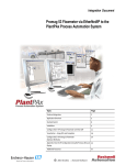
1
Integration Document Promass 100 Flowmeter via EtherNet/IP to the PlantPAx Process Automation System Topic Page Preferred Integration 2 Application Overview 4 Example System 8 Installation 9 Configure the E+H Promass 100 Flowmeter with the AOP 16 Visualization – Using AOIs and Faceplates 28 Appendix: Configure via Web Server 32 Additional Resources 34 Preferred Integration Rockwell Automation and Endress+Hauser have strengthened their strategic alliance to provide complete process automation solutions that use best-in-class instrumentation, software, and control systems. There are hundreds of different components in a typical plant: controllers, remote I/O, electrical drives, safety equipment, and sensors. Each must be integrated, configured, and optimized during start-up and operation. Recognizing the challenges this creates, Rockwell Automation and Endress+Hauser are focused on providing scalable, off-the-shelf solutions. To reduce the risks associated with integrating many devices from many different suppliers, Rockwell Automation pretests many third-party manufactured HART, FOUNDATION Fieldbus, EtherNet/IP, and PROFIBUS PA field devices in the system test laboratory for compatibility with the Rockwell Automation PlantPAx automation system. Each field device is connected to the PlantPAx system and is subjected to interoperability testing procedures similar to operating procedures in your plant. The results of each field test are recorded in a test report for integration planning purposes. For Endress+Hauser field devices, an additional step provides an “Integration Document” and “Interoperability Statement” for each tested instrument. The Integration Document provides information on installation, configuration, startup, and operation of the integrated system. The Interoperability Statement is assurance that the Endress+Hauser field device meets PlantPAx system interoperability performance measures, as jointly established by Rockwell Automation and Endress+Hauser and verified through completion of common test procedures performed by either company. Both the Integration Document and Interoperability Statement help reduce risk and provide ease of integration. The overall mission of the alliance is to provide proven solutions that combine field instrumentation with fieldbus networks, such as HART, FOUNDATION Fieldbus, PROFIBUS PA, and EtherNet/IP networks, with asset management capabilities and Rockwell Automation’s system capabilities to provide a total engineered solution. Through preferred integration and support of increasing requirements for plant-wide control, the alliance offers the following benefits: • Reduced integration costs throughout engineering, commissioning, and start-up • Optimized plant availability and output • Ensured product quality and consistency • Optimized traceability to meet regulatory demands • Predictive maintenance through intelligent instruments For new construction, process improvements at an existing plant, or operating cost reductions, the alliance delivers the following: • Certified integration reduces risk, reduces integration costs, and protects investment with pre-engineered interoperability. Both companies believe open systems and standardized interfaces bring maximum benefits. • Advanced capabilities with plant-wide asset management provides better visibility of plant health and easier access to instrument diagnostics, which ultimately leads to faster troubleshooting and improves decision-making. Application Overview This document provides a step-by-step approach to integrating an Endress+Hauser Promass 100 Coriolis Mass Flow Measuring System into a Rockwell Automation PlantPAx process automation system via EtherNet/IP. This Section Describes Application overview Details about the field instrument and control system. System details Specifications on the required hardware and software components. Installation How to connect the measurement instrument to the EtherNet/IP interface. Configuration (two separate sections) How to: • Configure the EtherNet/IP interface. • Configure the measurement instrument. Visualization How to implement and configure a graphical display of device information. The ControlLogix platform provides a robust EtherNet/IP backbone for communication to process fieldbus networks. The PlantPAx system architecture uses producer/consumer technology, allowing input information and output status to be shared by all ControlLogix controllers in the system. This integration document assumes you have a working knowledge of ControlLogix systems. For more details regarding the equipment and tasks described in this document, see Additional Resources on page 38. Promass Flowmeter Promass measuring instruments make it possible to simultaneously record several process variables (mass/density/temperature) for various process conditions during measuring operation. Promass sensors, tried and tested in over 100,000 applications, offer the following: • Multivariable flow measurement in compact design • Insensitivity to vibrations thanks to balanced two-tube measuring system • Immunity from external piping forces due to robust design • Easy installation without taking inlet and outlet runs into consideration The measuring principle is based on the controlled generation of Coriolis forces. In the sensor, two parallel measuring tubes containing flowing fluid oscillate in antiphase, acting like a tuning fork. The Coriolis forces produced at the measuring tubes cause a phase shift in the tube oscillations. At zero flow, when the fluid is at a standstill, the two tubes oscillate in phase (1). Mass flow causes deceleration of the oscillation at the inlet of the tubes (2) and acceleration at the outlet (3). T h e p The phase difference (A-B) increases with increasing mass flow. Electrodynamic sensors register the tube oscillations at the inlet and outlet. System balance is ensured by the antiphase oscillation of the two measuring tubes. The measuring principle operates independently of temperature, pressure, viscosity, conductivity, and flow profile. Measured Variables • Mass flow (proportional to the phase difference between two sensors; mounted on the measuring tube to register a phase shift in the oscillation) • Volume flow (calculated from mass flow and fluid density; the density is proportional to the resonance frequency of the measuring tubes) • Measuring tube temperature (by temperature sensors) for calculatory compensation of temperature effects • Density (by monitoring the tube frequency; is directly proportional to medium density) • Totalized flow Instrument Specifications • Communication: Standard, EtherNet/IP™ up to 100 Mbps – ODVA™ compliant – IEEE 802.3 • Supply voltage: 20 to 30 VDC • Ambient temperature: -40 to +60 °C (-40 to +140 °F) • Degree of protection: IP 66/67 (NEMA 4X) • Approvals: CE marked for nonhazardous area application – ATEX/IECEx – C CSA US • EMC: IEC/EN 61326 and NAMUR Recommendation NE21 • Device configuration: Multiple options • Ethernet connection: Bus Plug: 4-pole M12 connector per IEC 61076-2-10 • IP Addressing: Configurable EtherNet/IP and Web server addresses – Hardware device addressing by DIP switches – Software device addressing by integrated Web server – DHCP or Static IP addressing supported • Status condition: Four LEDs for communication status • Security: Password protected with four definable levels • Data mapping: (16) Autoscan registers for data transmission: – Preconfigured for easy integration but can be user-defined – Positions 1 to 10 for input value reporting – Positions 11 to 16 for output control • Integrated Web server: Operation supported in standard web browser • EDS file: Embedded in the device for RSLogix 5000 integration • Add-on profile: Available for Promass 100 with EtherNet/IP IMPORTANT The use of DLR requires Stratix 4000 EtherNet Tap. Control System The control system includes these components: Component Description Controller The Logix controller is a modular, high performance controller, which uses RSLogix 5000 programming software to configure, program, and monitor a system. EtherNet/IP Communication The EtherNet/IP Communication Module serves as a linking device/bridge module. Seamless integration into control systems with direct EtherNet/IP connection, e.g., ControlLogix, CompactLogix or PlantPAx from Rockwell Automation is possible. Programming software PlantPAx is an easy object-oriented, explorer-based, drag-and-drop configuration that allows you to build complex process functions. Furthermore, the software allows you to mix and match IEC61131-3 compliant programming languages. All supported programming languages share the same development environment, tag database, and user interface, resulting in reduced training and higher productivity. Visualization software FactoryTalk® View Site Edition software is an HMI software program for monitoring, controlling, and acquiring data from manufacturing operations throughout an enterprise. A faceplate provides a graphical representation of the instrument through the Operator Work Station. Faceplates associated with every instruction help you set up, tune, and control the element with a minimum of effort. Additions and modifications can be performed online, while your process keeps running. Example System Endress+Hauser and Rockwell Automation interoperability testing is performed for every new device and product. Hardware Components Component Catalog Number Promass 100 Coriolis Flowmeter 8F1B08-*N******-**** EtherNet/IP Communications Module 1756-EN2T ControlLogix Control System 1756-L63 For further details, see the PlantPAx Process Automation System Selection Guide, publication PROCES-SG001-EN-P. Software Components Component Catalog Number PlantPAx RSLogix 5000 Enterprise Series programming software, Professional edition 9324-RLD700NXENE Includes: • RSLinx Classic software • RSLinx Enterprise software FactoryTalk View Site Edition (SE) software (optional) 9701-VWSXXXXXENE FactoryTalk AssetCentre server (optional) 9515-ASTSRVRENE FactoryTalk AssetCentre process device configuration (optional) 9515-ASTPRDCFENE E+H FieldCare Standard Asset Management software (optional) SFE500 For additional information on drivers, see Additional Resources on page 34. For specifications of the engineering workstation (EWS) and operator workstation (OWS), see the PlantPAx Process Automation System Reference Manual, publication PROCES-RM001. Installation The information in this section provides a summary of the installation procedures. IMPORTANT For complete installation instructions, including warnings, see Additional Resources on page 34. Installation can be accomplished by utilizing fieldbus connectors. The method is described below. Transmitter Pin Assignment, Device Plug Connect a Promass 100 Flowmeter 1. Depending on the housing version, loosen the securing clamp or fixing screw of the housing cover, and then unscrew or open the housing cover. 2. Push the cable through the cable entry. IMPORTANT To ensure a tight seal, do not remove the sealing ring from the cable entry. 3. Strip the cable and cable ends. In the case of stranded cables, also fit ferrules. 4. Connect the cable in accordance with the terminal assignment or the connector pin assignment. 5. Depending on the device version, tighten the cable glands or plug in the connector and tighten. IMPORTANT The degree of protection for the DIP housing is voided if there is insufficient sealing of the housing. Ensure that you attach the screw without using any lubricant. The threads on the cover are coated with a dry lubricant. 6. Reassemble the transmitter by reversing the removal procedure. Diagnostic Information via the Light-emitting Diodes Various light emitting diodes (LEDs) on the main electronics module of the transmitter provide information on device status. LED Color Meaning Power Off Supply voltage is off or too low. Green Supply voltage is OK. Green Flashing red Device status is OK. A device error of diagnostic behavior “Warning” has occurred. Red A device error of diagnostic behavior “Alarm” has occurred. Alternately flashing red/green Boot loader is active. Off Device has no EtherNet/IP address. Green EtherNet/IP connection of the device is active. Flashing green Device has EtherNet/IP address but no EtherNet/IP connection. Red EtherNet/IP address of the device has been assigned twice. Flashing red EtherNet/IP connection of the device is in timeout mode. Orange Link available but no activity Flashing orange Activity present Device status Network status Link/Activity Configure the Device Address The IP address of the measuring device can be configured for the EtherNet/IP network through the DIP switches for hardware addressing or through software settings. The IP address for software addressing is active when the device leaves the factory (default IP address: 192.168.1.212), and all the DIP switches for hardware addressing are set to OFF. Dynamic Host Configuration Protocol (DHCP) Client If a DHCP server is used within the EtherNet/IP network, the IP address, gateway and subnet mask are set automatically when the DHCP client function is enabled. The MAC address of the measuring device is used for identification purposes. (See also the connection label.) The default setting for the DHCP server is ON. IMPORTANT The DHCP client function is disabled if hardware addressing is enabled. Hardware Addressing IMPORTANT The Dual In-line Package (DIP) switches can configure the last octet of the IP address. 1. Depending on the housing version, loosen the securing clamp or fixing screw of the housing cover, and then unscrew or open the housing cover. 2. Set the desired IP address using the corresponding DIP switches on the I/O electronics module. Hardware addressing with the configured IP address is enabled after 10 seconds. 3. Reassemble the transmitter by reversing the removal procedure.. Software Addressing Software addressing is carried out in the Communication submenu, using the navigation path Setup > Communication in the Web Server. When delivered, the measuring device has the following factory settings: IP address 192.168.1.212 Subnet mask 255.255.255.0 Default gateway 192.168.1.212 IMPORTANT • If hardware addressing is activated, software addressing is disabled. • If a switch is changed to the ON position, then the first three octets of the software address are retained. • If the IP address of the device is not known, the device address currently configured can be read by activating dip switch No. 10, restarting the device and logging on to the Web server. Install the E+H Promass 100 AddOn Profile (AOP) An AOP is a way to bring a definition of a new Allen-Bradley device or devices from our Encompass partners into RSLogix 5000. These profiles will vary, depending on the manufacturing and function of the target device. All contain some configuration and automatic tag creation, so you do not have to figure out how data is mapped or spend time creating aliases to point at the generic tags. This section describes how to install an AOP from Endress+Hauser for a Promass 100 Mass Flowmeter. Note: The AOP is preinstalled in RSLogix 5000 versions 21 and higher. 1. Download the Promass 100 AOP from http://www.products.endress.com/ethernet-ip-eds. 2. Double click the MPSetup.exe file from the download location. The setup screen is displayed. 3. Click Next, and on subsequent screens, continue to follow the prompts, accepting the default selections and clicking Next. 4. When a screen saying that the setup is complete is displayed, click Finish. The AOP is installed and available to add to the RSLogix 5000 Project, as described in the following section. Load the Electronic Data Sheet (EDS) File Although the EDS file for this device is typically included in the installation of the AOP, it is also available for you to install separately. If necessary, you can access it from the device through RSLinx or the Web Server or the manufacturer’s website. If you want to access the EDS file from... Then... the device through RSLinx 1. Go to RSLinx, Communication and open the Network view under RSWho. 2. Right-click on the device and select Upload EDS File from device. the device through the Web Server 1. Go to the Network Configuration screen. 2. Click the button Load EDS File. http://www.products.endress.com/eth 1. Download the EDS file. ernet-ip-eds 2. Save the file to your desktop. 3. Double click the file and follow the on-screen prompts. IMPORTANT Use the RSLinx EDS Hardware Installation Tool to install the EDS file. Configure the E+H Promass 100 Flowmeter with the AOP There are several options to configure the I/O in the Add On Profile (AOP). The option “Device Configuration via the AOP” described in the procedure below is used as an example. In the RSLogix 5000 project, ensure that the Ethernet Module(s) and communication settings are established before installing the Promass 100. For assistance with setting up Ethernet communications via the ControlLogix Platform, refer to www.rockwell.com or ask the local Rockwell Automation distributor. Establish the Configuration of the E+H AOP 1. On the left side of the RSLogix 5000 project screen, right click the Ethernet Module, and then select New Module. 2. Click the Catalog tab, select Promass_100, and then click OK. IMPORTANT Do not click OK in the Module Properties screen until you have completed defining the module, as described in steps 3 through 5. 3. In the Module Properties screen: a. Enter the necessary information in the Name and Ethernet Address fields. b. In the Module Definition section, click Change. 4. In the Module Definition screen: a. Click the Connection Type/s drop-down list and select Fixed I/O, Custom Input Only. b. Click OK. c. For more information about the available connections in the AOP, refer to the table below: Config Assembly Yes* or No Number of Connections Connections Types 1 2 Fixed I/O Fixed I/O, Custom Input Only Custom Input + Fixed Ouput Fixed Input Only, Custom Input Only Fixed Input Only Custom Input Only *If using the AOP for device configuration (Config. Assembly: Yes), the configuration in the device is overwritten with every Forward Open command. If you choose Config Assembly: No then you have to use the Web Server or FieldCare to configure the device. IMPORTANT Do not click OK in the Module Properties screen, until you ensure that the module properties have the settings that you prefer. 5. If preferred, you can customize the Endress+Hauser Promass 100 AOP properties using the tabs at the top of the Module Properties screen. • In the Connection screen, you can set the Requested Packet Interval (RPI) and other communication parameters. • In the Module Info screen, you can view the device information. • In the Internet Protocol screen, you can set up the Internet protocol. • In the Port Configuration screen, you can set up the port configuration. • In the Medium Selection screen, you can define the fluid being measured. • In the System Units screen, you can configure the measuring units. • In the Supervision screen, you can configure the diagnostic behavior and Write Protection parameters. • In the Totalizers (1,2,3) screen, you can configure the device totalizers and the measuring units. • In the Process Parameters screen, you can configure the process parameters such as Flow Override and Density Damping. • In the Calculated Value screen, you can configure the Calculate Volume Calculation. • In the External Compensation screen, you can configure the External Compensation method. • In the Low Flow Cut Off screen, you can configure the Low Flow Cut Off function. • In the Partially Filled Pipe Detection screen, you can configure the Partially Filled Pipe Detection. • In the Sensor Adjustment screen, you can configure the sensor flow direction. • In the Custom Input Connection screen, you can configure the Custom Input connection. • In the Vendor screen, you can view the vendor information. 6. When the module is defined according to your preferences, in the Module Properties screen, click OK. 7. In the RSLogix 5000 warning screen, click Yes to complete the Promass module setup. 8. Ensure that you save the RSLogix 5000 file first, and then download the file to the ControlLogix controller. Visualization – Using AOIs and Faceplates To monitor the instruments using the predesigned faceplates, the EtherNet/IP must be set up as specified in this integration document and the manual. The controller exchanges data between the devices, and the FactoryTalk View SE faceplates notify personnel what is happening in the plant. The following information allows you to customize the Promass 100 and set up the function blocks to use the Add-On Instructions (AOI) with an HMI server. See Additional Resources on page 34 for more detailed information. Add-On Instructions An Add-On Instruction exchanges data between each process variable located in the process device and the faceplate installed on a display. The name of the specific instance of the Add-On Instruction becomes the link from the actual instrument to the faceplate on the graphic. Global Object A global object links the tag name to the faceplate, provides a touch area for the faceplate to be launched from, and displays the process variables and alarms. IMPORTANT A unique global object and faceplate are available for each field instrument due to each instrument having specific extended diagnostics. Faceplates The FactoryTalk View SE generic display provides a graphical representation of the instrument based on the information contained within each Add-On Instruction. Navigation buttons at the top of the faceplate change the information displayed. Status displays show information using a bar graph, numeric values, and trend displays. Other displays show specific alarms and warning indications. Some examples of predesigned faceplates are shown below. IMPORTANT A unique global object and faceplate are available for each field instrument due to the display of instrument-specific extended diagnostic information. The faceplates provide the following information from the device: • Process values • PV fault status (communication fault) • Device extended status You can configure the faceplates to provide the following information: • • • • • • • • Tag name Description Engineering units Mode (such as operator or program) High-high, high, low, low-low alarms Over-range and under-range alarms Alarm delay Alarm hysteresis Appendix: Configure via Web Server Configuring the Internet Protocol of the Computer The device has the following default EtherNet settings: Note: The factory setting for the device IP address is: 192.168.1.212. IP address 192.168.1.XXX; for XXX, all numerical values except: 0, 212, and 255 Example: 192.168.1.213 Subnet mask 255.255.255.0 Default gateway 192.168.1.212 1. Switch on the measuring device, and connect it to the computer using the cable. 2. Configure the properties of the Internet protocol (TCP/IP) as defined in the table above. Starting the Web Server 1. Start the Web Server on the computer. 2. If the IP address of the measuring device is known, enter the defined device address in the address line of the Web browser. The login screen is displayed. Disabling the Web Server The Web server of the measuring device can be switched on and off as required using the Web server functionality parameter. Navigation path Menu tab "Expert" menu Communication Web server Web server functionality Parameter Description Web Server functionality Switch the Web Server on and off Options • • Off On Factory Settings On Enabling the Web Server If the Web server is disabled it can only be re-enabled with the Web server functionality parameter via the following operating options: "FieldCare" operating tool Additional Resources Resource Description EtherNet/IP Field Instruments Proline Promass 100 Technical Information, publication TI01034DEN Specifications and details of the Promass 100E flowmeter Proline Promass 100 Operating Instructions (Proline Promass EtherNet I/P) publication BA01065DEN How to install, wire, configure, and operate a Promass 100 flowmeter http://www.products.endress.com/ethernet-ip-eds Download EDS and AOP files for field instrument http://www.products.endress.com/flow Information about Endress+Hauser flowmeters Control System Components ControlLogix Controllers Installation Instructions, publication 1756-IN101 How to install and configure a ControlLogix controller. ControlLogix Controllers User Manual, publication 1756-UM001 How to configure, operate, and maintain a ControlLogix controller. ControlLogix Ethernet/IP Modules 1756-IN612B-EN-P Installation Instructions, ControlLogix EtherNet/IP Communication Module Operator Components FactoryTalk View Site Edition User’s Guide, publication VIEWSE-UM006 How to design, develop, and deploy FactoryTalk View SE applications Faceplates, Add-On Instructions, project files, etc. http://rockwellautomation.com/knowledge base (Login required. Please contact your sales representative.) Download AOIs, Faceplates and Global Object graphics, project files, and documents Process Control Information Notes: 2012 Rockwell Automation Support Rockwell Automation provides technical information on the Web to assist you in using its products. At http://support.rockwellautomation.com, you can find technical manuals, a knowledge base of FAQs, technical and application notes, sample code and links to software service packs, and a MySupport feature that you can customize to make the best use of these tools. For an additional level of technical phone support for installation, configuration, and troubleshooting, we offer TechConnect support programs. For more information, contact your local distributor or Rockwell Automation representative, or visit http://support.rockwellautomation.com. Endress+Hauser Support Please refer to your local Endress+Hauser Sales Center for precise information regarding the service support available in your area or visit http://www.endress.com. Installation Assistance If you experience a problem within the first 24 hours of installation, please review the information that's contained in this manual. You can also contact a special Customer Support number for initial help in getting your product up and running. United States 1.440.646.3434 Monday – Friday, 8 a.m. – 5 p.m. EST Outside United States Please contact your local Rockwell Automation representative for any technical support issues. New Product Satisfaction Return Rockwell Automation tests all of its products to ensure that they are fully operational when shipped from the manufacturing facility. However, if your product is not functioning and needs to be returned, follow these procedures. United States Contact your distributor. You must provide a Customer Support case number (call the phone number above to obtain one) to your distributor in order to complete the return process. Outside United States Please contact your local Rockwell Automation representative for the return procedure. Allen-Bradley, ControlLogix, FactoryTalk, Rockwell Automation, RSLinx, RSLogix 5000, and TechConnect are trademarks of Rockwell Automation, Inc. Trademarks not belonging to Rockwell Automation are property of their respective companies. E+H Publication SP00031A/04/en/01.12 Copyright © 2012 Endress+Hauser, Inc. RA Publication PROCESS-AP060A-EN-P – September 2012 Copyright © 2012 Rockwell Automation, Inc. All rights reserved. Printed in the U.S.A.