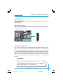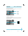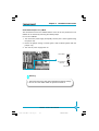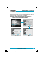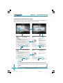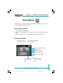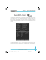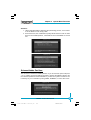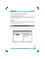
1
Statement:
This manual is the intellectual property of Foxconn, Inc. Although the
information in this manual may be changed or modified at any time,
Foxconn does not obligate itself to inform the user of these changes.
Trademark:
All trademarks are the property of their respective owners.
Intel® and Pentium® are registered trademarks of Intel Corporation.
PS/2 and OS/2 is the registered trademarks of IBM, Inc.
Windows® 95/98/2000/NT/XP is the registered trademark of Microsoft.
Award® is the registered trademark of Award, Inc.
Version:
User’s Manual V1.0 in English for 600A01 series motherboard.
P/N:91-181-600-10-00
Symbol description:
Note: refers to important information that can help you to use motherboard
better.
Attention: indicates that it may damage hardware or cause data loss,
and tells you how to avoid such problems.
Warning: means that a potential risk of property damage or physical
injury exists.
More information:
If you want more information about our products, please visit Foxconn’s
website: www.foxconnchannel.com
600M01-English preface.p65
1
2004-4-12, 13:33
Item Checklist:
Thank for your purchasing Foxconn’s 600A01 series motherboard. Please check
the package; if there are missing or damaged items, contact your distributor as
soon as possible.
600A01 Series Motherboard (x1)
Foxconn Utility CD (x1)
User’s Manual (x1)
600A01 Flyer (x1)
IDE Ribbon Cable (x1)
FDD Ribbon Cable (x1)
I/O Shield (x1)
SPDIF Cable (x1) (optional)
USB 2.0 Cable (x1) (optional)
S-ATA Signal Cable (x1) (optional)
S-ATA Power Cable (x1) (optional)
Serial ATA RAID Floppy Disk (x1) (optional)
600M01-English preface.p65
2
2004-4-12, 13:33
Declaration of conformity
HON HAI PRECISION INDUSTRY COMPANY LTD
66 , CHUNG SHAN RD., TU-CHENG INDUSTRIAL DISTRICT,
TAIPEI HSIEN, TAIWAN, R.O.C.
declares that the product
Motherboard
600A01 series
is in conformity with
(reference to the specification under which conformity is declared in
accordance with 89/336 EEC-EMC Directive)
EN 55022/A1: 2000
Limits and methods of measurements of radio disturbance
characteristics of information technology equipment
EN 61000-3-2/A14:2000 Electromagnetic compatibility (EMC)
Part 3: Limits
Section 2: Limits for harmonic current emissions
(equipment input current <= 16A per phase)
EN 61000-3-3/A1:2001
Electromagnetic compatibility (EMC)
Part 3: Limits
Section 2: Limits of voltage fluctuations and flicker in low-voltage
supply systems for equipment with rated current <= 16A
EN 55024/A1:2001
Information technology equipment-Immunity characteristics limits
and methods of measurement
Signature :
Printed Name :
Place / Date :
James Liang
600M01-English preface.p65
Position/ Title :
3
TAIPEI/2004
Assistant President
2004-4-12, 13:33
Declaration of conformity
Trade Name:
Model Name:
Responsible Party:
Foxconn
600A01
PCE Industry Inc.
Address:
458 E. Lambert Rd.
Fullerton, CA 92835
714-738-8868
714-738-8838
Telephone:
Facsimile:
Equipment Classification:
Type of Product:
Manufacturer:
FCC Class B Subassembly
Motherboard
HON HAI PRECISION INDUSTRY
COMPANY LTD
66 , CHUNG SHAN RD., TU-CHENG
INDUSTRIAL DISTRICT, TAIPEI HSIEN,
TAIWAN, R.O.C.
Address:
Supplementary Information:
This device complies with Part 15 of the FCC Rules. Operation is subject to the
following two conditions : (1) this device may not cause harmful interference, and (2)
this device must accept any interference received, including interference that may
cause undesired operation.
Tested to comply with FCC standards.
Signature :
600M01-English preface.p65
Date :
4
2004
2004-4-12, 13:33
Table of Contents
Chapter
1
Product Introduction
Main Features .............................................................................................. 2
Motherboard Layout .................................................................................... 5
Chapter
2
Installation Instructions
CPU ............................................................................................................. 11
Memory ...................................................................................................... 13
Power Supply ............................................................................................ 16
Rear Panel Connectors .............................................................................. 17
Other Connectors ...................................................................................... 19
Expansion Slots ......................................................................................... 27
Jumpers ..................................................................................................... 30
Chapter
3
BIOS Description
Enter BIOS Setup .......................................................................................
Main Menu .................................................................................................
Standard CMOS Features ..........................................................................
BIOS Features ...........................................................................................
34
34
36
39
Advanced BIOS Features .......................................................................... 40
Advanced Chipset Features ...................................................................... 43
Integrated Peripherals ................................................................................ 48
Power Management Setup ......................................................................... 52
PnP/PCI Configurations ............................................................................... 58
PC Health Status ........................................................................................ 60
Frequency/Voltage Control ......................................................................... 61
Load Fail-Safe Defaults ............................................................................. 62
Load Optimized Defaults ............................................................................ 62
Set Supervisor/User Password ................................................................. 62
Save & Exit Setup ...................................................................................... 63
Exit Without Saving .................................................................................... 63
600M01-English preface.p65
5
2004-4-12, 13:33
Table of Contents
Chapter
4
Driver CD Introduction
Utility CD content ........................................................................................
Start to install drivers .................................................................................
Install VIA 4in1 Driver .................................................................................
Install DirectX 9.0b .....................................................................................
Install VIA RAID (optional) ..........................................................................
Install USB 2.0 Driver .................................................................................
Using 6-Channel Audio ...............................................................................
Install LAN Driver .......................................................................................
Install IR Driver ...........................................................................................
Install Norton Internet Security 2004 ..........................................................
Chapter
65
66
66
68
69
70
70
74
75
76
5 Directions for Bundled Software
SuperStep ................................................................................................. 78
SuperLogo ................................................................................................. 81
SuperUpdate .............................................................................................. 83
Chapter
6
Special BIOS Functions
SuperSpeed ...............................................................................................
SuperBoot .................................................................................................
SuperBIOS-Protect ....................................................................................
SuperRecovery .........................................................................................
89
90
91
92
Appendix
Using Serial ATA RAID (optional) .............................................................. 101
600M01-English preface.p65
6
2004-4-12, 13:33
Warning:
1. Attach the CPU and heatsink using silica gel to ensure full contact.
2. It is suggested to select high-quality, certified fans in order to avoid
damage to the motherboard and CPU due to high temperatures.
3. Never turn on the machine if the CPU fan is not properly installed.
4. Ensure that the DC power supply is turned off before inserting or
removing expansion cards or other peripherals, especially when
you insert or remove a memory module. Failure to switch off the DC
power supply may result in serious damage to your system or
memory module.
Warning:
We cannot guarantee that your system will operate normally while
over-clocked. Normal operation depends on the over-clock capacity of
your device.
Attention:
Since BIOS programs are upgraded from time to time, the BIOS description in this manual is just for reference. We do not guarantee that
the content of this manual will remain consistent with the actual BIOS
version at any given time in the future.
Attention:
The pictures of objects used in this manual are just for your reference.
Please refer to the physical motherboard.
600M01-English preface.p65
7
2004-4-12, 13:33
This page is intentionally left blank.
600M01-English preface.p65
8
2004-4-12, 13:33
1
Chapter
Thank you for your buying Foxconn’s 600A01 series
motherboard. This series of motherboard is one of our new
products and offers superior performance, reliability and
quality, at a reasonable price. This motherboard adopts the
advanced VIA KT600 + VT8237 chipset, providing users a
computer platform with a high integration-compatibility-performance price ratio.
This chapter includes the following information:
600A01-FOXCONN-V1.0-HW-en.p65
1
Main Features
Motherboard Layout
2004-4-12, 13:29
Chapter 1
Product Introduction
Main Features
Size
ATX form factor of 12”x 8.1”
Microprocessor
Supports AMD socket 462 K7, DuronTM, AthlonTM, AthlonTM XP processors
Supports FSB at 200MHz/266MHz/333MHz/400MHz
Chipset
VIA chipset: KT600 (North Bridge)+VT8237 (South Bridge)
System Memory
Three 184-pin DIMM slots
Supports PC2100/PC2700/PC3200 memory
Supports 128/256/512 Mb technology up to 3GB
Onboard IDE
Supports up to 4 independent drives
Supports Ultra DMA 133/100/66/33
Two fast IDE interfaces supporting four IDE devices, including IDE hard disk
and CD-ROM/DVD-ROM drives
Onboard Serial ATA (optional)
150MB/s transfer rate
Supports two S-ATA devices
Supports Raid0, Raid1 and JBOD
USB 2.0 Ports
Supports hot plug
Eight USB 2.0 ports (four rear panel ports, two onboard USB headers providing four extra ports)
Supports wake-up from S1 and S3 mode
Supports USB 2.0 protocol up to 480 Mbps transmission rate
2
600A01-FOXCONN-V1.0-HW-en.p65
600A01 Series User Manual
2
2004-4-12, 13:29
Chapter 1
Product Introduction
Onboard 1394 (optional)
Supports hot plug
With rate of transmission up to 400Mbps
Self-configured addressing
Can connect with 2 independent 1394 units synchronously at most, such
as HDD, CD-ROM
Onboard LAN
VIA VT6103L 10/100Mbps Ethernet PHY
LAN interface built-in on board
Onboard Audio
AC’ 97 2.2 Specification Compliant
Supports 48KHz of S/PDIF output
Onboard Line-in jack, Microphone jack, Line-out jack
Supports 5.1 channels audio (setting via software)
AGP 8X support
AGP 8X (AGP 3.0) is the VGA interface specification that enabled enhanced
graphics performance with high handwidth speeds up to 2.12 GB/s
Expansion Slots
Five PCI slots
One AGP slot
One CNR slot (optional)
BIOS
Licensed advanced AWARD (Phoenix) BIOS, supports flash ROM, plugand-play ready
Supports HDD, CD-ROM, SCSI HDD, LAN or USB device boot up
3
600A01 Series User Manual
600A01-FOXCONN-V1.0-HW-en.p65
3
2004-4-12, 13:29
Chapter 1
Product Introduction
Green Function
Supports ACPI (Advanced Configuration and Power Interface)
Supports S0 (normal), S1 (power on suspend), S3 (suspend to RAM), S4
(suspend to disk – depends on OS) and S5 (soft-off)
Advanced Features
PCI 2.2 Specification Compliant
Supports Windows 98/ME/2000/XP soft-off
Supports Wake-on-LAN, Wake-on-Modem
Supports PC Health function (capable of monitoring system voltage, CPU
temperature, system temperature and fan speed)
4
600A01-FOXCONN-V1.0-HW-en.p65
600A01 Series User Manual
4
2004-4-12, 13:29
Chapter 1
Product Introduction
Motherboard Layout
16
15
14
1
13
2
12
3
11
4
5
10
6
9
7
8
Note:
The above motherboard layout is provided for reference only;
please refer to the physical motherboard.
5
600A01 Series User Manual
600A01-FOXCONN-V1.0-HW-en.p65
5
2004-4-12, 13:29
Chapter 1
Product Introduction
1 Super I/O controller
The VIA VT1211 I/O controller offers support for a variety of I/O function.
Provides a high-performance floppy disk controller for a 360K/720K/1.44M/
2.88M floppy disk drive, a multi-mode parallel port, two serial ports, and
a Flash ROM interface.
2 ATX power connector
This 20-pin connector connects to an ATX power supply. The power supply
must have at least 1A on the +5V standby lead (+5VSB).
3 AGP slot
This Accelerated Graphics Port (AGP) slot supports 1.5V AGP 8X/4X mode
graphics cards for 3D graphical applications.
4 CPU socket
Socket 462 (socket A) Zero Insertion Force (ZIF) for the AMD processor,
with 200/266/333/400MHz system bus.
5 North Bridge controller
The VIA KT600 controller integrates a high performance host interface for
the AMD processor, a DDR memory controller, and support AGP 8X
technology.
6 DDR DIMM sockets
These three 184-pin DIMM sockets support up to 3GB system memory
using unbuffered non-ECC PC2100/PC2700/PC3200 DDR DIMMs.
7 South Bridge controller
The VIA VT8237 integrated peripheral South Bridge controller communicates
with the North Bridge at the rates of up to 533MB/s using the VIA 8X VLink
technology. This controller supports standard UltraATA 133/100/66/33 and
provides separate data paths for each IDE channel for up to two IDE devices.
This controller also integrates SATA RAID controller, Ethernet MAC, Universal
Serial Bus Host controller.
8 Serial ATA connectors (optional)
These connectors support Serial ATA HDDs and allow for up to 150MB/s
data transfer rate, faster than the standard Parallel ATA with 133MB/s.
6
600A01-FOXCONN-V1.0-HW-en.p65
600A01 Series User Manual
6
2004-4-12, 13:29
Chapter 1
Product Introduction
9 IDE connectors
These dual-channel bus master IDE connectors support Ultra DMA 133/
100/66/33 devices. Both the primary (blue) and secondary (white)
connectors are slotted to prevent incorrect insertion of the IDE ribbon cable.
10 Floppy disk connector
This connector accommodates the provided ribbon cable for the floppy disk
drive. One side of the connector is slotted to prevent incorrect insertion of
the floppy disk cable.
11 PCI slots
These five 32-bit PCI 2.2 expansion slots support bus master PCI cards
like SCSI or LAN cards with 133MB/s maximum throughput.
12 CNR slot (optional)
This slot is specifically designed for the Communication and Networking
Riser (CNR) card. The CNR supports V.90 analog modem only.
13 Flash Rom
This 4Mb firmware contains the programmable BIOS program.
14 Audio CODEC
The VIA VT1616 provides 6-channel outputs fully supporting surround sound
applications, along with 4 stereo and 2 mono inputs. Supporting the AC’97
2.2 specification, the VIA VT1616 enables 20-bit resolution, and a variable
sampling rate with 1Hz resolution.
15 1394 controller (optional)
VT6307 is the controller for IEEE1394a on motherboard. The VT6307 is a
complete small package single chip PCI solution at 400Mbps, low power
seamless plug and play connections to the latest IEEE 1394 enabled
devices.
16 10/100M LAN PHY
The VT6103L is a single-port PHY transceiver with an MII (Media
Independent Interface) and supports 10/100 Mbps data transfer rate.
7
600A01 Series User Manual
600A01-FOXCONN-V1.0-HW-en.p65
7
2004-4-12, 13:29
Chapter 2
Installation Instructions
2
Chapter
This chapter introduces the hardware installation process,
including the installation of the CPU and memory. It also
addresses the connection of your power supply, use of the
rear panel connectors, connection of hard drive and floppy
drive data cables, and setting up various other feature of the
motherboard. Caution should be exercised during the installation process. Please refer to the motherboard layout prior to any installation and read the contents in this
chapter carefully.
This chapter includes the following information:
CPU
Memory
Power Supply
Rear Panel Connectors
Other Connectors
Expansion Slots
Jumpers
8
600A01-FOXCONN-V1.0-HW-en.p65
600A01 Series User Manual
8
2004-4-12, 13:29
Chapter 2
Installation Instructions
Notes:
Take note of the following precautions before you install components or change settings.
1. Use a grounded wrist strap or touch a safely grounded object,
such as an attached power supply, before handling components to avoid damaging them due to static electricity.
2. Unplug the power cord before opening your chassis or touching
any component.
3. Hold components by their edges to avoid touching any exposed
integrated circuits (ICs).
4. Whenever you uninstall a component, place it on a grounded
anti-static pad or into anti-static bag that it came in.
9
600A01 Series User Manual
600A01-FOXCONN-V1.0-HW-en.p65
9
2004-4-12, 13:29
Chapter 2
Installation Instructions
CPU
This motherboard accepts socket 462 processors (CPUs) with a front side bus
(FSB) of 200/266/333/400MHz.
Warning :
The CPU pins must be properly aligned with the holes in the
socket, otherwise the CPU may be damaged.
Installation of CPU
Follow these steps to install a CPU.
90°
1. Unlock the socket by pressing the
lever sideways, then lift it up to a 900
Gap in the base
angle.
2. Align the cut edge to the gap in the
base of the socket. Carefully insert
the CPU into the socket until it fits in
place.
Cut edge
Push down the socket
lever to secure the CPU
3. When the CPU is in place, press it
firmly on the socket while you push
down the socket lever to secure the
CPU. The lever clicks on the side
tab to indicate that it is locked.
10
600A01-FOXCONN-V1.0-HW-en.p65
600A01 Series User Manual
10
2004-4-12, 13:29
Chapter 2
Installation Instructions
Installation of CPU Fan
New technology allows processors to run at higher and higher frequencies. To
avoid problems arising from high-speed operation, for example, overheating, you
need to install the proper fan. The following procedures are provided for reference only, please refer to your CPU fan user guide to install it.
1. Locate the CPU retention mechanism 2.
base (surrounds the CPU socket).
If required, apply a light coating
of silica gel to the top of the CPU.
Note: The CPU heatsink may have a
pre-applied thermal compound. In that
case, the silica gel is not required.
3.
Attach the fan to the base.
4. Connect the power fan’s power
cable to the appropriate 3-pin
connector on the motherboard.
Warning :
Excessive temperatures will severely damage the CPU and
system. Therefore, make sure that the cooling fan works normally
at all times in order to prevent overheating and damaging to the
CPU.
11
600A01 Series User Manual
600A01-FOXCONN-V1.0-HW-en.p65
11
2004-4-12, 13:30
Chapter 2
Installation Instructions
CPU Qualified Vendor List
The following table lists the CPU modules that have been tested and qualified
for use with this motherboard.
Vendor
Type
FSB
AMD
Athlon3200+
400MHz
AMD
Athlon3000+
333MHz
AMD
Athlon2800+
333MHz
AMD
Athlon2600+
333MHz
AMD
Athlon2500+
333MHz
AMD
Athlon2400+
266MHz
AMD
Athlon2200+
266MHz
AMD
Athlon1700+
266MHz
12
600A01-FOXCONN-V1.0-HW-en.p65
600A01 Series User Manual
12
2004-4-12, 13:30
Chapter 2
Installation Instructions
Memory
This motherboard includes three, 184-pin, dual in-line memory module (DIMM)
sockets. You can install corresponding PC3200 (DDR400), P C 2 7 0 0
(DDR333), PC2100 (DDR266) memory modules. You must install at least
one memory module to ensure normal operation. If you install two modules,
they must be the same speed. Mixing memory modules from different
manufacturers is not recommended.
DIMM1
DIMM2
DIMM3
13
600A01 Series User Manual
600A01-FOXCONN-V1.0-HW-en.p65
13
2004-4-12, 13:30
Chapter 2
Installation Instructions
Memory Qualified Vendor List
Vender
Type
Size
Transcend
PC3200 (DDR 400)
512MB
MT
PC2700 (DDR 333)
256MB
KingMax
PC2100 (DDR 266)
256MB
TwinMos
PC3200 (DDR 400)
512MB
KingMax
PC2700 (DDR 333)
256MB
ADATA
PC2700 (DDR 333)
256MB
Samsung
PC3200 (DDR 400)
256MB
Rambo
PC3200 (DDR 400)
256MB
Hynix
PC3200 (DDR 400)
256MB
Hynix
PC2700 (DDR 333)
256MB
Rambo
PC2700 (DDR 333)
512MB
Hynix
PC2100 (DDR 266)
256MB
MT
PC3200 (DDR 400)
256MB
MT
PC3200 (DDR 400)
512MB
Nanya
PC2100 (DDR266)
512MB
Kingston
PC3200 (DDR 400)
512MB
Note:
Make sure to use only the tested and qualified DDR DIMMs
listed above. Other DDR DIMMs manufactured by other vendors may not be suitable for this motherboard.
14
600A01-FOXCONN-V1.0-HW-en.p65
600A01 Series User Manual
14
2004-4-12, 13:30
Chapter 2
Installation Instructions
Installation of DDR Memory
1. There is only one gap in the center of the DIMM socket, and the memory
module can be fixed in one direction only. Unlock a DIMM socket by
pressing the module clips outward.
2. Align the memory module to the DIMM socket and insert the module vertically into the DIMM socket.
104
Pins
80
Pins
3. The plastic clips at both sides of the DIMM socket will lock automatically.
Warning :
Be sure to unplug the AC power supply before adding or removing expansion cards or other system peripherals, especially the
memory devices, otherwise your motherboard or the system
memory might be seriously damaged.
15
600A01 Series User Manual
600A01-FOXCONN-V1.0-HW-en.p65
15
2004-4-12, 13:30
Chapter 2
Installation Instructions
Power Supply
This motherboard uses an ATX power supply. In order to avoid damaging any
devices, make sure that they have been installed properly prior to connecting
the power supply.
20-pin ATX power connector: PWR1
PWR1 is the ATX power supply connector. Make sure that the power supply
cable and pins are properly aligned with the connector on the motherboard.
Firmly plug the power supply cable into the connector and make sure it is secure.
20-pin ATX power connector
3D3V_SYS 5V_SYS 5V_SYS Power OK 12V_SYS
3D3V_SYS Ground Ground Ground
5V_SB
1
10
20
11
3D3V_SYS Ground Ground Ground 5V_SYS
-12V_SYS PS-ON Ground
NC
Attention:
You have to press the power button for more than four seconds if
you change the default “Instant-Off” setting to “Delay 4 Sec.” from
the “Soft-Off by PWRBTN” option in the BIOS “Power Management Setup”.
16
600A01-FOXCONN-V1.0-HW-en.p65
600A01 Series User Manual
16
2004-4-12, 13:30
5V_SYS
Chapter 2
Installation Instructions
Rear Panel Connectors
This motherboard provides the ports as below:
4 Parallel Port
(Printer Port)
7
1394 Port
(optional)
8
LAN Connector
Line-in jack
1 PS/2 Mouse
Connector
Line-out jack
9
Microphone
2 PS/2 Keyboard
Connector
jack
3
Serial Port
(COM1)
5
Serial Port
(COM2)
6 USB 2.0 Port x 4
PS/2 Mouse Connector
This green 6-pin connector is for a PS/2 mouse.
1
2
PS/2 Keyboard Connector
This purple 6-pin connector is for a PS/2 keyboard.
3
Serial Port (COM1)
This 9-pin COM1 port is for pointing devices or other serial devices.
Parallel Port (Printer Port)
This 25-pin port connects a parallel printer, a scanner, or other devices.
4
5
Serial Port (COM2)
This 9-pin COM2 port is for pointing devices or other serial devices.
6
USB 2.0 Ports
These four Universal Serial Bus (USB) ports are available for connecting USB
2.0/1.1 devices.
7
1394 Port (optional)
This digital interface supports electronic devices such as digital cameras,
scanners and printers.
17
600A01 Series User Manual
600A01-FOXCONN-V1.0-HW-en.p65
17
2004-4-12, 13:30
Chapter 2
Installation Instructions
LAN Connector
This port allows connection to a Local Area Network (LAN) through a network
8
hub.
Line-in jack, Line-out jack, Microphone jack
The Line-in jack connects a tape player or other audio sources. In 6-Channel
9
mode, the function of this jack becomes Rear Speaker Out.
The Line-out jack connects a headphone or a speaker. In 6-Channel mode, the
function of this jack becomes Front Speaker Out.
The Microphone jack connects a microphone. In 6-Channel mode, the function
of this jack becomes Center/Subwoofer Speaker.
18
600A01-FOXCONN-V1.0-HW-en.p65
600A01 Series User Manual
18
2004-4-12, 13:30
Chapter 2
Installation Instructions
Other Connectors
This motherboard includes connectors for FDD, IDE HDD, USB, CPU fan, system
fan, and others.
FDD Connector: FLOPPY
This motherboard includes a standard FDD connector, supporting 360K, 720K,
1.2M, 1.44M and 2.88M FDDs.
1
FDD connector
HDD Connectors: PIDE & SIDE
The connectors support the provided UltraDMA 133/100/66/33 IDE hard disk
ribbon cable. Connect the cable’s blue connector to the primary
(recommended) or secondary IDE connector, then connect the gray connector to the Ultra DMA 133/100/66/33 slave device (hard disk drive) and the black
connector to the Ultra DMA 133/100/66/33 master device. If you install two hard
disks, you must configure the second drive as a slave device by setting its
jumper accordingly. Refer to the hard disk documentation for the jumper
settings.
Attention:
Ribbon cables are directional, therefore, make sure to always
connect with the cable on the same side as pin 1 of the PIDE/
SIDE or FDD connector on the motherboard.
19
600A01 Series User Manual
600A01-FOXCONN-V1.0-HW-en.p65
19
2004-4-12, 13:30
Chapter 2
Installation Instructions
PIDE
SIDE
1
Front Panel Connector: FP1
This motherboard includes one connector for connecting the front panel switch
and LED indicators.
+
PLED
-
1+
IDE_LED
RESET
PWRBTN#
NC
FP1
Hard Disk LED Connector (IDE_LED)
The connector connects to the case’s IDE indicator LED indicating the activity
status of hard disk.
Reset Switch (RESET)
Attach the connector to the Reset switch on the front panel of the case; the
system will restart when the switch is pressed.
Power LED Connector (PLED)
Attach the connector to the power LED on the front panel of the case. The Power
LED indicates the system’s status. When the system is in S0 status, the LED is
on. When the system is in S1 status, the LED is blink. When the system is in S3,
S4, S5 status, the LED is off.
20
600A01-FOXCONN-V1.0-HW-en.p65
600A01 Series User Manual
20
2004-4-12, 13:30
Chapter 2
Installation Instructions
IrDA Header: IR
This connector supports wireless transmitting and receiving device. Before using
this function, set the item “Onboard Fast IR” to enabled from the “Integrated
Peripherals” section of the CMOS Setup. Then install IR driver to make sure this
function takes effect.
+5V
1
Empty
RX
Ground
TX
IR
Fan Connectors : CPU_FAN, FAN1
The speed of CPU_FAN and FAN1 can be detected and viewed in “PC Health
Status” section of the CMOS Setup.
1
GND
SENSE
+12V
GND
+12V
CPU_FAN
SENSE
FAN1
1
21
600A01 Series User Manual
600A01-FOXCONN-V1.0-HW-en.p65
21
2004-4-12, 13:30
Chapter 2
Installation Instructions
USB Headers: F_USB1, F_USB2
Besides four USB ports on the rear panel, the series of motherboards also have
two 10-pin headers on board which may connect to front panel USB cable
(optional) to provide additional four USB ports. The USB headers complies with
USB 2.0 specification that supports up to 480 Mbps connection speed.
VCC
D4-
1
VCC
D0-
D4+
D0+
GND
GND
GND
Empty
F_USB1
1
VCC
VCC
D6-
D7-
D6+
D7+
GND
GND
GND
Empty
F_USB2
Note:
1. You must install the driver before you can use the USB 2.0
function.
2. NEVER connect a 1394 cable to the F_USB1 or F_USB2
connector. Doing so will damage the motherboard!
3. The USB cable is an optional item.
22
600A01-FOXCONN-V1.0-HW-en.p65
600A01 Series User Manual
22
2004-4-12, 13:30
Chapter 2
Installation Instructions
Audio Connector: CD_IN, AUX_IN
CD_IN, AUX_IN is Sony standard CD audio connector, it can be connected to a
CD-ROM drive through a CD audio cable.
1
CD_L GND CD_R
CD_IN
1
AUX_R GND AUX_L
AUX_IN
1394 Header: F_1394 (optional)
The 1394 expansion cable can be connected to either the front (provided that
the front panel of your chassis is equipped with the appropriate interface) or
real panel of the chassis.
Empty
GND
12V
12V
TPB -
TPB +
GND
GND
TPA +
TPA -
1
F_1394
23
600A01 Series User Manual
600A01-FOXCONN-V1.0-HW-en.p65
23
2004-4-12, 13:30
Chapter 2
Installation Instructions
Wake-Up On LAN: WOL
Through the Wake-Up On LAN function, a wake event occurring from the network can wake up the system. To utilize this function, please be sure an ATX 12V
power supply with a 5VSB line capable of delivering a current of at least 1A, and
a LAN adapter which supports this function. Then connect the header to the
relevant connector on the LAN adapter, set “PowerOn by PCI Card” to enabled
in the “Power Management Setup” section of the CMOS Setup. Save and exit,
then boot the operating system once to make sure this function takes effect.
Signal for waking up
GND
5VSB
1
WOL
Wake-Up On Internal Modem: WOM
Through this function, the system which is in the suspend or soft-off status can
be waked up by a ring signal received from the internal modem. When this
function is used, be sure an internal modem card which supports this function
is used. Then connect the header to the relevant connector on the modem card,
set “Modem Ring Resume” to enabled in the “Power Management Setup” section of the CMOS Setup. Save and exit, then boot the operating system once to
make sure this function takes effect.
Signal for waking up
GND
5VSB
1
WOM
24
600A01-FOXCONN-V1.0-HW-en.p65
600A01 Series User Manual
24
2004-4-12, 13:30
Chapter 2
Installation Instructions
Serial ATA Connectors: SATA_1, SATA_2 (optional)
The Serial ATA header is used to connect the Serial ATA device to the
motherboard. These connectors support the thin Serial ATA cables for primary
internal storage devices. The current Serial ATA interface allows up to 150MB/s
data transfer rate, faster than the standard parallel ATA with 133MB/s (Ultra ATA/
133).
RX+
GND
TX+
GND
RXTXGND
SATA_1/SATA_2
Audio Interface: F_AUDIO
The audio interface provides two kinds of audio output choices: the Front Audio,
the Rear Audio. Their priority is sequenced from high to low (Front Audio to Rear
Audio). If headphones are plugged into the front panel of the chassis (using the
Front Audio), then the Line-out (Rear Audio) on the rear panel will not work. If you
do not want to use the Front Audio, pin 5 and 6, pin9 and 10 must be short, and
then the signal will be sent to the rear audio port.
1
MIC_IN
MIC_GND
MIC_PWR
+5VA
RET_R
OUT-R
NC
Empty
OUT_L
RET_L
F_AUDIO
25
600A01 Series User Manual
600A01-FOXCONN-V1.0-HW-en.p65
25
2004-4-12, 13:30
Chapter 2
Installation Instructions
SPDIF Out Connector: SPDIF_OUT
The SPDIF output connector is capable of providing digital audio to external
speakers, or compressed AC3 data to an external Dolby digital decoder.
GND
OUT
Empty
1
+5V
SPDIF_OUT
Chassis Intruder Jumper: INTR
To utilize this function, please connect the header to the relevant connector on
the chassis. Then set “Chassis intrude detection” to ON in the “Power Management Setup” section of the CMOS Setup. Save and exit, then boot the opeating
system once to make sure this function takes effect.
1
2
INTR
26
600A01-FOXCONN-V1.0-HW-en.p65
600A01 Series User Manual
26
2004-4-12, 13:30
Chapter 2
Installation Instructions
Expansion Slots
This motherboard includes five 32-bit Master PCI bus slots, one AGP slot, one
CNR slot (optional).
PCI Slots
The expansion cards can be installed in the five PCI slots. When you install or
take out such cards, you must make sure that the power plug has been pulled
out. Please read carefully the instructions provided for such cards, and install
and set the necessary hardware and software for such cards, such as the
jumper or BIOS setup.
PCI Slots
AGP Slot
This motherboard has an AGP slot that supports 1.5V AGP card. AGP is an
interfacing specification designed to display 3D images. It provides a specialized 66Mhz, 32-bit channel to allow the graphic controller to directly access the
master memory, and supports 4X and 8X speeds.
AGP slot
27
600A01 Series User Manual
600A01-FOXCONN-V1.0-HW-en.p65
27
2004-4-12, 13:30
Chapter 2
Installation Instructions
Warning:
The motherboard may be damaged if a 3.3V AGP card is used. Make
sure that your AGP card is 1.5V specification. Note the notches on
the card golden fingers to ensure that they fit the AGP slot on your
motherboard.
Installing an expansion card
1. Before installing the expansion card, read carefully the documentation that
came with it and make the necessary hardware settings for the card.
2. Make sure to unplug the power cord before adding or removing any expansion cards.
3. Remove the bracket opposite the slot that you intend to use.
4. Align the card connector with the slot and press firmly until the card is
completely seated in the slot.
5. Secure the card to the chassis with the screw you removed earlier.
AGP Qualified Vendor List
The following table lists the AGP cards that have been tested and qualified for
use with this Motherboard.
Vender
CP
Type
Video Memory
ATI Radeon 7000
64MB DDR
CP
ATI 9700 AGP
128MB DDR
CP
ATI 9800 AGP
128MB DDR
ECS
ECS-315T
32MB SDRAM
UNIKA
GeForce 4 MX400
32MB SDRAM
LeadTek
S650
128MB DDR
GA
GA-GF 1280 GeForce 2 MX
32MB SDRAM
Elsa
Elsa 511
64MB DDR
MSI
MSI 8912 (FX5600)
128MB DDR
MSI
MSI 8911(FX5200)
128MB DDR
28
600A01-FOXCONN-V1.0-HW-en.p65
600A01 Series User Manual
28
2004-4-12, 13:30
Chapter 2
Installation Instructions
Note:
Make sure to use only the tested and qualified AGP cards listed
above. Other AGP cards manufactured by other vendors may not
be suitable for this motherboard.
CNR Slot (optional)
The motherboard provides this Communication and Networking Riser (CNR)
interface which can support modem function. Mechanically the CNR shares the
PCI5 slot, thus when you insert the CNR card, the neighboring PCI5 slot cannot
be used.
CNR
29
600A01 Series User Manual
600A01-FOXCONN-V1.0-HW-en.p65
29
2004-4-12, 13:30
Chapter 2
Installation Instructions
Jumpers
The users can change the jumper settings on this motherboard if needed. This
section explains how to use the various functions of this motherboard by
changing the jumper settings. Users should read the following contents
carefully prior to modifying any jumper settings.
Description of Jumpers
1.
2.
For the jumpers on this motherboard, pin 1 can be identified by the silkscreen printed “
” next to it. However, in this manual, pin 1 is simply
labeled as “1”.
The following table provides some explanation of the jumper pin settings.
User should refer to this when adjusting jumper settings.
Jumper
1
1
Diagram
Definition
Description
1
1-2
Set pin1 and pin2 closed
1
2-3
Set pin2 and pin3 closed
1
Closed
Set the pin closed
1
Open
Set the pin opened
CPU Selection Jumper: J21
Set the jumper as close when the CPU’s external frequency you used is 100MHz.
Otherwise leave this jumper to default.
Close
1
2
Open
1
(Default)
2
J21
30
600A01-FOXCONN-V1.0-HW-en.p65
600A01 Series User Manual
30
2004-4-12, 13:30
Chapter 2
Installation Instructions
Clear CMOS Jumper: CLR_CMOS
This motherboard uses the CMOS RAM to store all the set parameters. The
CMOS can be cleared by removing the CMOS jumper.
How to clear CMOS?
1. Turn off the AC power supply and quickly connect pins 1 and 2 together using
the jumper cap.
2. Return the jumper setting to normal (pins 2 and 3 locked together with the
jumper cap).
3. Turn the AC power supply back on.
Clear CMOS
3
2
1
3
Normal Status
(Default)
2
1
CLR_CMOS
Warning:
1. Disconnect the power cable before adjusting the jumper settings.
2. Do not clear the CMOS while the system is turned on.
31
600A01 Series User Manual
600A01-FOXCONN-V1.0-HW-en.p65
31
2004-4-12, 13:30
Chapter 2
Installation Instructions
Starting up for the first time
1. After making all the connections, replace the system case cover.
2. Be sure that all switches are off.
3. Turn on the devices in the following order.
a.
b.
Monitor
External SCSI devices (starting with the last device on the chain)
c. System power
4. After applying power LED on the system front panel case lights up. For ATX
power supplies, the system LED lights up when you press the ATX power
switch. If your monitor complies with green standards or if it has a power
standby feature, the monitor LED may light up or switch between orange and
green after the system LED turns on. The system then runs the power-on
tests. While the tests are running, the BIOS beeps or additional messages
appear on the screen. If you do not see anything within 30 seconds from the
time you turned on the power, the system may have failed a power-on test.
Check the jumper settings and connections or call your retailer for assistance.
5. At power on, hold down <Delete> to enter BIOS Setup. Follow the instructions
in Chapter 3.
Powering off the computer
1. Using the OS shut down function
If you use windows 98/ME/2000/XP, click the Start button, click Shut Down,
then click the OK button to shut down the computer. The power supply should
turn off after Windows shuts down.
2. Using the dual function power switch
While the system is ON, pressing the power switch for less than 4 seconds
puts the system to sleep mode or to soft-off mode, depending on the BIOS
setting. Pressing the power switch for more than 4 seconds lets the system
enter the soft-off mode regardless of the BIOS setting.
32
600A01-FOXCONN-V1.0-HW-en.p65
600A01 Series User Manual
32
2004-4-12, 13:30
Chapter 3
BIOS Description
3
Chapter
This chapter tells how to change system settings through the
BIOS Setup menus. Detailed descriptions of the BIOS parameters
are also provided.
You have to run the Setup Program when the following cases
occur:
1. An error message appears on the screen during the system
POST process.
2. You want to change the default CMOS settings.
This chapter includes the following information:
Enter BIOS Setup
Main Menu
Standard CMOS Features
BIOS Features
Advanced BIOS Features
Advanced Chipset Features
Integrated Peripherals
Power Management Setup
PnP/PCI Configurations
PC Health Status
Frequency/Voltage Control
Load Fail-Safe Defaults
Load Optimized Defaults
Set Supervisor/User Password
Save & Exit Setup
Exit Without Saving
600A01 Series User Manual
600A01-FOXCONN-V1.0-BIOS-en.p65
33
33
2004-4-12, 13:31
Chapter 3
BIOS Description
Enter BIOS Setup
The BIOS is the communication bridge between hardware and software,
correctly setting up the BIOS parameters is critical to maintain optimal system
performance. Power on the computer, when the following message briefly
appears at the bottom of the screen during the POST (Power On Self Test),
press <Del> key to enter the Award BIOS CMOS Setup Utility.
Press TAB to show POST Screen, DEL to enter SETUP.
Note:
We do not suggest that you change the default parameters in the
BIOS Setup, and we shall not be responsible for any damage that
result from any changes that you make.
Main Menu
The main menu allows you to select from the list of setup functions and two exit
choices. Use the arrow keys to select among the items and press <Enter> to
accept or go to the sub-menu.
Main Menu
The items in the main menu are explained as below:
Standard CMOS Features
The basic system configuration can be set up through this menu.
BIOS Features
The special features can be set up through this menu.
34
600A01-FOXCONN-V1.0-BIOS-en.p65
600A01 Series User Manual
34
2004-4-12, 13:31
Chapter 3
BIOS Description
Advanced BIOS Features
The advanced system features can be set up through this menu.
Advanced Chipset Features
The values for the chipset can be changed through this menu, and the system performance can be optimized.
Integrated Peripherals
All onboard peripherals can be set up through this menu.
Power Management Setup
All the items of Green function features can be set up through this menu.
PnP/PCI Configurations
The system’s PnP/PCI settings and parameters can be modified through
this menu.
PC Health Status
This will display the current status of your PC.
Frequency/Voltage Control
Frequency and voltage settings can be adjusted through this menu.
Load Fail-Safe Defaults
The default BIOS settings can be loaded through this menu.
Load Optimized Defaults
The optimal performance settings can be loaded through this menu,
however, the stable default values may be affected.
Set Supervisor Password
The supervisor password can be set up through this menu.
Set User Password
The user password can be set up through this menu.
Save & Exit Setup
Save CMOS value settings to CMOS and exit setup.
Exit Without Saving
Abandon all CMOS value changes and exit setup.
35
600A01 Series User Manual
600A01-FOXCONN-V1.0-BIOS-en.p65
35
2004-4-12, 13:31
Chapter 3
BIOS Description
Standard CMOS Features
This sub-menu is used to set up the standard CMOS features, such as the date,
time, HDD model and so on. Use the arrow keys select the item to set up, and
then use the <PgUp> or <PgDn> keys to choose the setting values.
Standard CMOS Features Menu
Date
This option allows you to set the desired date (usually as the current date)
with the <day><month><date><year> format.
Day—weekday from Sun. to Sat., defined by BIOS (read-only).
Month—month from Jan. to Dec..
Date—date from 1st to 31st, can be changed using the keyboard.
Year—year, set up by users.
Time
This option allows you to set up the desired time (usually the current time) with
<hour><minute><second> format.
IDE Channel 0/1 Master/ Slave
These categories identify the HDD types of 2 IDE channels installed in the
computer system. There are three choices provided for the Enhanced IDE BIOS:
None, Auto, and Manual. “None” means no HDD is installed or set; “Auto” means
the system can auto-detect the hard disk when booting up; by choosing “Manual”
and changing Access Mode to “CHS”, the related information should be entered
manually. Enter the information directly from the keyboard and press < Enter>:
Cylinder
number of cylinders
Precomp
write pre-compensation Landing Zone
Sector
number of sectors
36
600A01-FOXCONN-V1.0-BIOS-en.p65
Head
number of heads
landing zone
600A01 Series User Manual
36
2004-4-12, 13:31
Chapter 3
BIOS Description
Award (Phoenix) BIOS can support 3 HDD modes: CHS, LBA and Large or Auto mode.
CHS
For HDD<528MB
LBA
For HDD>528MB & supporting LBA (Logical Block Addressing)
Large
For HDD>528MB but not supporting LBA
Auto
Recommended mode
IDE Channel 2/3 Master (optional)
These two items will show after you set “SATA Mode” as IDE in CMOS Setup and
restart your computer. In this way, Serial ATA hard disk will be used to IDE hard
disk.
Drive A/B
This option allows you to select the kind of FDD to be installed, including “None”,
[360K, 5.25 in], [1.2M, 5.25 in], [720K, 3.5 in], [1.44M, 3.5 in] and [2.88 M, 3.5 in].
Video
The following table is provided for your reference in setting the display mode for
your system.
EGA/VGA
Enhanced Graphics Adapter / Video Graphic Array. For EGA,
VGA, SEGA, SVGA, or PGA monitor adapters.
CGA 40
Color Graphic Adapter, powering up in 40 column mode.
CGA 80
Color Graphic Adapter, powering up in 80 column mode.
MONO
Monochrome adapter, including high resolution monochrome
adapters.
37
600A01 Series User Manual
600A01-FOXCONN-V1.0-BIOS-en.p65
37
2004-4-12, 13:31
Chapter 3
BIOS Description
Halt On
This category determines whether or not the computer will stop if an error is
detected during powering up.
All Errors
No Errors
All, But Keyboard
All, But Diskette
All, But Disk/Key
Whenever the BIOS detects a nonfatal error, the system
will stop and you will be prompted.
The system boot will not stop for any errors that may
be detected.
The system boot will not stop for a keyboard error; but
it will stop for all other errors.
The system boot will not stop for a diskette error; but
it will stop for all other errors.
The system boot will not stop for a keyboard or disk
error, but it will stop for all other errors.
Memory
This is a Display-Only Category, determined by POST (Power On Self Test) of
the BIOS.
Base Memory
The BIOS POST will determine the amount of base (or
conventional) memory installed in the system.
Extended Memory
The BIOS determines how much extended memory
is present during the POST.
Total Memory
Total memory of the system.
38
600A01-FOXCONN-V1.0-BIOS-en.p65
600A01 Series User Manual
38
2004-4-12, 13:31
Chapter 3
BIOS Description
BIOS Features
BIOS Features Menu
[SuperBoot] SuperBoot (Default: Disabled)
SuperBoot allows system-relevant information to be stored in CMOS upon the
first normal start-up of your PC, and the relevant parameters will be restored
to help the system start up more quickly on each subsequent start-up. The
available setting values are: Disabled and Enabled.
[SuperBIOS-Protect] SuperBIOS-Protect (Default: Disabled)
SuperBIOS-Protect function protects your PC from being affected by viruses,
e.g. CIH. The available setting values are: Disabled and Enabled.
[SuperRecovery] SuperRecovery Hotkey (Default: LSHIFT+F12)
SuperRecovery provides the users with an excellent data protection and HDD
recovery function. There are 12 optional hotkey and the default hotkey is
LSHIFT+F12.
[SuperSpeed] CPU Clock (Depending on the specification of the CPU)
The conventional over-clock method uses the jumpers on the motherboard,
and it is both troublesome and apt to errors. By using SuperSpeed, a CPU
can be overclocked by keying in the desired in the CPU clock range.
Warning:
Be sure your selection is right. CPU overclock will be dangerous!
We will not be responsible for any damage caused.
39
600A01 Series User Manual
600A01-FOXCONN-V1.0-BIOS-en.p65
39
2004-4-12, 13:31
Chapter 3
BIOS Description
Advanced BIOS Features
Advanced BIOS Features Menu
Hard Disk Boot Priority
This option is used to select the priority for HDD startup. After pressing
<Enter>, you can select the HDD using the <PageUp>/<PageDown> or up/
down arrow keys, and change the HDD priority using <+> or <->; you can
exit this menu by pressing <Esc>.
Virus Warning (Default: Disabled)
Allows you to choose the VIRUS warning feature for IDE hard disk boot sector
protection. If this function is enabled and someone attempt to write data into
this area, BIOS will show a warning message on screen and an alarm will
beep. The setting values are: Disabled and Enabled.
Note: Such function provides protection to the start-up sector only; it does
not protect the entire hard disk.
CPU L1 & L2 Cache (Default: Enabled)
This option is used to enable or disable the L1 and L2 CPU cache. The
available setting values are: Disabled and Enabled.
CPU L2 Cache ECC Checking (Default: Enabled)
This option is used to enable or disable CPU L2 cache ECC Checking. The
setting values are: Disabled and Enabled.
Quick Power On Self Test (Default: Enabled)
Enable this option to shorten the power on testing (POST) and have your system start up faster. The setting values are: Disabled and Enabled.
First/Second/Third Boot Device (Default: Floppy/Hard Disk/CDROM)
This option allows you to set the boot device’s sequence. The setting
values are: Floppy, LS120, Hard Disk, CDROM, ZIP100, USB-FDD, USBZIP, USB-CDROM, LAN and Disabled.
40
600A01-FOXCONN-V1.0-BIOS-en.p65
600A01 Series User Manual
40
2004-4-12, 13:31
Chapter 3
BIOS Description
Boot Other Device (Default: Enabled)
With this function set to enable, the system will boot from some other devices if the first/second/third boot devices failed. The setting values are: Disabled and Enabled.
Swap Floppy Drive (Default: Disabled)
If you have two floppy diskette drives in your system, this option allows you to
swap the assigned drive letters. The setting values are: Disabled and Enabled.
Boot Up Floppy Seek (Default: Enabled)
If this option is enabled, BIOS will tests floppy drives to determine whether
they have 40 or 80 tracks.The setting values are: Disabled and Enabled.
Boot Up NumLock Status (Default: On)
This option defines if the keyboard Num Lock key is active when your system
is started. The setting values are: On and Off.
Typematic Rate Setting (Default: Disabled)
If this option is enabled, you can use the following two items to see the
typematic rate and the typematic delay settings for your keyboard. The available setting values are: Disabled and Enabled.
Typematic Rate (Chars/Sec) (Default: 6)
Use this option to define how many characters per second a held-down
key generated.
Typematic Delay (Msec) (Default: 250)
Use this option to define how many milliseconds must elapse before a helddown key beings generating repeat characters.
Security Option (Default: Setup)
When it is set to “Setup”, a password is required to enter the CMOS Setup
screen; When it is set to “System”, a password is required not only to enter
CMOS Setup, but also to start up your PC.
APIC Mode (Default: Enabled)
This option is used to enable or disable APIC mode. The available setting
values are: Disabled and Enabled.
41
600A01 Series User Manual
600A01-FOXCONN-V1.0-BIOS-en.p65
41
2004-4-12, 13:31
Chapter 3
BIOS Description
OS Select For DRAM > 64MB (Default: Non-OS2)
This option is only required if you have installed more than 64 MB of memory
and you are running the OS/2 operating system. Otherwise, leave this option
at the default.
Video BIOS Shadow (Default: Enabled)
This option is used to enable or disable Video BIOS Shadow. If you enable
this option, the video BIOS will be copied to RAM. Video shadow will increase
the video speed. The available setting values are: Disabled and Enabled.
Small Logo (EPA) Show (Default: Disabled)
This option allows you to enable or disable the EPA logo. The available setting
values are: Disabled and Enabled.
42
600A01-FOXCONN-V1.0-BIOS-en.p65
600A01 Series User Manual
42
2004-4-12, 13:31
Chapter 3
BIOS Description
Advanced Chipset Features
Advanced Chipset Features Menu
DRAM Clock/Drive Control
Press enter to set the items about DRAM Clock/Drive. Please refer to page 44.
AGP & P2P Bridge Control
Press enter to set the items about AGP & P2P bridge. Please refer to page 46.
CPU & PCI Bus Control
Press enter to set the items about CPU & PCI bus. Please refer to page 47.
Memory Hole (Default: Disabled)
This option is used to select memory hole. The setting values are: Disabled,
15M-16M.
System BIOS Cacheable (Default: Disabled)
Select “Enabled” to allow caching of the system BIOS which may improve
performance. If any other program writes to this memory area, a system error
may result. The available setting values are: Enabled and Disabled.
43
600A01 Series User Manual
600A01-FOXCONN-V1.0-BIOS-en.p65
43
2004-4-12, 13:31
Chapter 3
BIOS Description
DRAM Clock/Drive Control Menu
Current FSB Frequency
This option is used to show current FSB frequency.
Current DRAM Frequency
This option is used to show current DRAM frequency.
DRAM Clock (Default: By SPD)
This option is used to set DRAM clock.
DRAM Timing (Default: Auto By SPD)
Selects whether DRAM timing is controlled by the SPD (Serial Presence Detect)
EEPROM on the DRAM module. Setting to “Auto By SPD” enables DRAM timings to be determined by BIOS based on the configurations on the SPD.
Selecting “Manual” allows users to configure the DRAM timings manually.
The setting values are:Manual, Auto By SPD, Turbo, Ultra.
DRAM CAS Latency (Default: Depend on Memory)
When synchronous DRAM is installed, the number of clock cycles of CAS
latency depends on the DRAM timing.
Bank Interleave (Default: Depend on Memory)
This field selects 2-bank or 4-bank interleave for the installed SDRAM. Disable the function if 16MB SDRAM is installed.
Precharge to Active (Trp) (Default: Depend on Memory)
This option controls the number of cycles for Row Address Strobe (RAS) to
be allowed to precharge. If insufficient time is allowed for the RAS to
accumulate its charge before DRAM refresh, refresh may be incomplete
and DRAM may fail to retain data. This option applies only when synchronous DRAM is installed in the system.
44
600A01-FOXCONN-V1.0-BIOS-en.p65
600A01 Series User Manual
44
2004-4-12, 13:31
Chapter 3
BIOS Description
Active to Precharge(Tras) (Default: Depend on Memory)
This option is used to set active to precharge(Tras).
Active to CMD<Trcd> (Default: Depend on Memory)
When DRAM is refreshed, both rows and columns are addressed separately.
This setup option allows you to determine the timing of the transition from
RAS (row address strobe) to CAS (column address strobe). The less the
clock cycles, the faster the DRAM performance.
DRAM Command Rate (Default: Depend on Memory)
This setting controls the SDRAM command rate. Selecting 1T allows SDRAM
signal controller to run at 1T (T=clock cycles) rate. Selecting 2T makes SDRAM
signal controller run at 2T rate. 1T is faster than 2T.
DRAM Burst Length (Default: Depend on Memory)
This setting allows you to set the size of Burst-Length for DRAM. Bursting
feature is a technique that DRAM itself predicts the address of the next memory
location to be accessed after the first address is accessed. To use the feature,
you need to define the burst length, which is the actual length of burst plus the
starting address and allows internal address counter to properly generate
the next memory location. The bigger the size, the faster the DRAM
performance.
Write Recovery Time (Default: Depend on Memory)
This option allows you to set write recovery time. The setting values are: 2T, 3T.
TWTR for DDR400 ONLY (Default: Depend on Memory)
Increase DRAM performance.
45
600A01 Series User Manual
600A01-FOXCONN-V1.0-BIOS-en.p65
45
2004-4-12, 13:31
Chapter 3
BIOS Description
AGP & P2P Bridge Control Menu
AGP Aperture Size (Default: 64 M)
This option defines the size of the aperture if you use an AGP graphics adapter.
The aperture is a portion of the PCI memory address range dedicated for
graphic memory address space.
Note: This function does not work when onboard VGA is used.
AGP Mode (Default: 4X)
This option is used to set an appropriate mode for the installed AGP card.
AGP Fast Write (Default: Enabled)
This option enables or disables the AGP Fast Write feature. The Fast Write
technology allows the CPU to write directly to the graphics card without passing anything through the system memory and improves the AGP 4X speed.
Select “Enabled” only when your AGP card supports the feature. The setting
values are: Disabled and Enabled.
AGP Master 1 WS Write (Default: Disabled)
When “Enabled”, writes to the AGP (Accelerated Graphics Port) are executed
with one wait states. The setting values are: Disabled and Enabled.
AGP Master 1 WS Read (Default: Disabled)
When “Enabled”, reads to the AGP (Accelerated Graphics Port) are executed
with one wait states. The setting values are: Disabled and Enabled.
AGP 3.0 Calibration cycle (Default: Enabled)
This option allows you to enable or disable the AGP 3.0 calibration cycle. This
cycle ensures that the on-die termination impedance signal swing and slew
rate of the AGP signals are calibrated on a periodic basis to ensure signal
integrity. It is recommended to keep this setting enabled.
46
600A01-FOXCONN-V1.0-BIOS-en.p65
600A01 Series User Manual
46
2004-4-12, 13:31
Chapter 3
BIOS Description
CPU & PCI Bus Control Menu
PCI Master 0 WS Write (Default: Enabled)
This option allows you to enable or disable the support of PCI Master 0 Wait
State Write. The setting values are: Disabled and Enabled.
PCI Delay Transaction (Default: Enabled)
This option allows you to enable or disable PCI delay transaction. The setting
value are: Disabled and Enabled.
VLink 8X Support (Default: Enabled)
This option allows you to enable or disable the VLink 8X support. When
“Enabled”, it may increase system performance. The setting values are:
Disabled and Enabled.
47
600A01 Series User Manual
600A01-FOXCONN-V1.0-BIOS-en.p65
47
2004-4-12, 13:31
Chapter 3
BIOS Description
Integrated Peripherals
Integrated Peripherals Menu
VIA OnChip IDE Device
Press enter to set onchip IDE device. Please refer to page 49.
VIA OnChip PCI Device
Press enter to set onchip PCI device. Please refer to page 50.
SuperIO Device
Press enter to set onboard SuperIO device. Please refer to page 51.
Init Display First (Default: PCI Slot)
This option is used to set which display device will be used first when your PC
starts up. The setting values are: AGP and PCI Slot.
48
600A01-FOXCONN-V1.0-BIOS-en.p65
600A01 Series User Manual
48
2004-4-12, 13:31
Chapter 3
BIOS Description
VIA OnChip IDE Device Menu
OnChip SATA (Default: Enabled)(optional)
This option is used to enable or disable onchip SATA. The setting values are:
Disabled and Enabled.
SATA Mode(Default: RAID)(optional)
This option is used to select SATA mode. The setting values are: RAID and
IDE.
IDE DMA transfer access (Default: Enabled)
This option is used to enable or disable IDE DMA transfer access. The setting
values are: Disabled and Enabled.
OnChip IDE Channel0/1 (Default: Enabled)
The integrated peripheral controller contains an IDE interface with support for
two IDE channels. Choose “Enabled” to activate each channel separately.
The setting values are: Disabled and Enabled.
IDE Prefetch Mode (Default: Enabled)
This option is used to enable or disable IDE prefetch mode. The setting
values are: Disabled and Enabled.
Primary/Secondary Master/Salve PIO (Default: Auto)
These four items let you assign which kind of PIO (Programmed Input/Output)
is used by IDE devices. Choose Auto to let the system auto detect which PIO
mode is best or select a PIO mode from 0-4.
Primary/Secondary Master/Salve UDMA (Default: Auto)
UltraDMA technology provides faster access to IDE devices. If you install a
device that supports UltraDMA, change the appropriate item on this list to
Auto. The available setting values are: Disabled and Auto.
IDE HDD Block Mode (Default: Enabled)
This option is used to set whether the IDE HDD Block Mode is allowed. The
available setting values are: Disabled and Enabled.
49
600A01 Series User Manual
600A01-FOXCONN-V1.0-BIOS-en.p65
49
2004-4-12, 13:31
Chapter 3
BIOS Description
VIA OnChip PCI Device Menu
VIA-3058 AC97 Audio (Default: Auto)
“Auto” allows the motherboard’s BIOS to detect whether you’re using any
audio devices. If so, the onboard audio controller will be enabled. If not, the
onboard audio controller will be disabled. If you want to use different controller cards to connect audio connectors, set the option to “Disabled”. The setting values are: Disabled and Auto.
VIA-3068 MC97 Modem (Default: Disabled) (optional)
Setting to “Auto” allows the BIOS to auto-detect whether you’re using any
modem devices. If so, the onboard modem controller will be enabled. If not,
the onboard modem controller will be disabled. The setting values are: Disabled and Auto.
VIA-3043 OnChip LAN (Default: Enabled)
Setting to “Auto” allows the BIOS to auto-detect the LAN controller and
enable it. The setting values are: Disabled and Enabled.
Onboard Lan Boot ROM (Default: Disabled)
The option enables or disables the initialization of the onboard LAN Boot
ROM during bootup. The setting values are: Disabled and Enabled.
OnChip USB Controller (Default: All Enabled)
This option is used to set onchip USB controller.
OnChip EHCI Controller (Default: Enabled)
This option is used to enable or disable onchip EHCI controller. The setting
values are: Disabled and Enabled.
USB Keyboard/Mouse Support (Default: Disabled)
This option is used to enable or disable USB keyboard/mouse support. The
setting values are: Disabled and Enabled.
50
600A01-FOXCONN-V1.0-BIOS-en.p65
600A01 Series User Manual
50
2004-4-12, 13:31
Chapter 3
BIOS Description
SuperIO Device Menu
Onboard FDC Controller (Default: Enabled)
This option is used to set whether the Onboard FDC Controller is enabled.
The available setting values are: Disabled and Enabled.
Onboard Serial Port1/2 (Default: 3F8/IRQ4 / 2F8/IRQ3)
This option is used to assign the I/O address and interrupt request (IRQ) for
the onboard serial port 1/2.
Note: Do not try to set the same values for serial ports 1 and 2.
Onboard Parallel Port (Default: 378/IRQ7)
This option allows you to determine onboard parallel port controller I/O address and interrupt request (IRQ). The setting values are: Disabled, 378/IRQ7,
278/IRQ5 and 3BC/IRQ7.
Parallel Port Mode (Default: SPP)
Select an address and corresponding interrupt for the onboard parallel port.
The setting values are: SPP, EPP, ECP, ECP+EPP.
ECP Mode Use DMA (Default: 3)
When the Parallel Port Mode is set to ECP or ECP+ EPP, this option is used to
select the channel for the ECP mode. The setting values are: 1 and 3.
Onboard Fast IR (Default: Disabled)
This option is used to enable or disable onboard fast IR. The setting values
are: Disabled and Enabled.
Fast IR IRQ (Default: 11)
This option is used to set fast IR IRQ. The setting values are: 11, 5, 3, 4.
Fast IR DMA (Default: 6)
This option is used to set fast IR DMA. The setting values are: 6, 5.
51
600A01 Series User Manual
600A01-FOXCONN-V1.0-BIOS-en.p65
51
2004-4-12, 13:31
Chapter 3
BIOS Description
Power Management Setup
Power Management Setup Menu
ACPI function (Default: Enabled)
ACPI stands for “Advanced Configuration and Power Interface”. ACPI is a
standard that defines power and configuration management interfaces between an operating system and the BIOS. In other words, it is a standard that
describes how computer components work together to manage system
hardware. In order to use this function the ACPI specification must be supported by the OS (for example, Windows2000 or WindowsXP). The available
setting values are: Enabled and Disabled.
ACPI Suspend Type (Default: S1(POS))
This option is used to set the energy saving mode of the ACPI function.
When you select “S1 (POS)” mode, the power will not shut off and the
supply status will remain as it is, in S1 mode the computer can be resumed
at any time. When you select “S3 (STR)” mode, the power will be cut off after
a delay period. The status of the computer before it enters STR will be saved
in memory, and the computer can quickly return to previous status when the
STR function wakes. When you select “S1 & S3” mode, the system will
automatically select the delay time.
Power Management Option (Default: User Define)
This option is used to set the power management scheme. The available
settings are: User Define, Min Saving and Max Saving.
HDD Power Down (Default: Disabled)
This option is used to define the continuous HDD idle time before the HDD
enters power saving mode. The setting values are: Disabled, 1 Min, 2 Min, 3
Min, 4 Min, 5 Min, 6 Min, 7 Min, 8 Min, 9 Min, 10 Min, 11 Min, 12 Min, 13 Min, 14
Min, 15 Min.
52
600A01-FOXCONN-V1.0-BIOS-en.p65
600A01 Series User Manual
52
2004-4-12, 13:31
Chapter 3
BIOS Description
Suspend Mode (Default: Disabled)
This option is used to set the idle time before the system enters into sleep
status. The setting values are: Disabled, 1 Min, 2 Min, 4 Min, 6 Min, 8 Min, 12
Min, 20 Min, 30 Min, 40 Min, 1 Hour.
Video Off Option (Default: Suspend -> Off)
This option is used to set video off option. The setting values are: Always On,
Suspend -> Off.
Video Off Method (Default: V/H SYNC+Blank)
This option is used to define the video off method. “Blank Screen” mode
means that after the computer enters into power saving mode, only the monitor
will close, however, the vertical and horizontal scanning movement of the screen
continues. When you select the “V/H SYNC + Blank” mode the vertical and horizontal scanning movement of screen stops when the computer enters power
saving mode. “DPMS Support” mode is a new screen power management
system, and it needs to be supported by the monitor you’re using.
MODEM Use IRQ (Default: 3)
This option is used to set the IRQ in which the modem can use. The setting
values are: NA, 3, 4, 5, 7, 9, 10, 11.
Soft-Off by PWRBTN (Default: Instant-Off)
This option is used to set the power down method. This function is only valid
for systems using an ATX power supply.
When “Instant-Off” is selected, press the power switch to immediately turn
off power.
When “Delay 4 Sec” is selected, press and hold the power button for four
seconds to turn off power.
Ac Loss Auto Restart (Default: Off)
The system will switch which status when power comes back after a power
failure. The setting values are: Auto, On, Off.
IRQ/Event Activity Detect
Press Enter to set IRQ/Event Activity Detect. Please refer to page 54.
53
600A01 Series User Manual
600A01-FOXCONN-V1.0-BIOS-en.p65
53
2004-4-12, 13:31
Chapter 3
BIOS Description
IRQ/Event Activity Detect Menu
PS2KB Wakeup Select (Default: Hot key)
This option is used to select which action will wake up PS/2 keyboard from S3
/S4/S5 staus. Use <PgUp> or <PgDn> to select the desired item. The setting
values are: Hot key, Password.
PS2KB Wakeup from S3/S4/S5 (Default: Disabled)
This option is used to select which hotkey will wake up by PS/2 keyboard from
S3/S4/S5 staus or disable it. The setting values are: Disabled, Ctrl + F1~F12,
Power, Wake, Any Key.
Power Button Lock (Default: Disabled)
This option allows you to enable or disable power button lock function. The
setting values are: Disabled and Enabled.
PS2MS Wakeup from S3/S4/S5 (Default: Disabled)
This option is used to enable or disable the system to be waken up by PS/2
mouse from S3/S4/S5 staus. The setting values are: Disabled and Enabled.
USB Resume from S3 (Default: Disabled)
This option is used to enable or disable the USB to be resume from S3. The
setting values are: Disabled and Enabled.
Chassis intrude detection (Default: Disabled)
This option is used to enable or disable chassis intrude detection function.
The setting values are: Disabled and Enabled.
VGA (Default: OFF)
When on of VGA, any activity from one of the listed system peripheral
devices or IRQs wakes up the system.The setting values are: ON and OFF.
LPT & COM (Default: LPT/COM)
When on of LPT & COM, any activity from one of the listed system peripheral
devices or IRQs wakes up the system. If select “NONE”, cannot wake up the
system. The setting values are: NONE, LPT, COM and LPT/COM.
54
600A01-FOXCONN-V1.0-BIOS-en.p65
600A01 Series User Manual
54
2004-4-12, 13:31
Chapter 3
BIOS Description
HDD & FDD (Default: ON)
When on of HDD & FDD, any activity from one of the listed system peripheral
devices or IRQs wakes up the system. The setting values are: OFF, ON.
PCI Master (Default: OFF)
When on of PCI master, any activity from one of the listed system peripheral
devices or IRQs wakes up the system. The setting values are: OFF and ON.
PowerOn by PCI Card (Default: Disabled)
If “Enabled” any PCI interrupt will wake up the system. The setting values are:
Disabled and Enabled.
Modem Ring Resume (Default: Disabled)
This option is used to set the system to be waked up by the modem ring. The
setting values are: Disabled and Enabled.
RTC Alarm Resume (Default: Disabled)
This option is used to set alarm to power on the system by the date (1-31) or
time (hh:mm:ss). The setting values are: Disabled and Enabled.
Date (of Month)
This option is used to set the timing for the start-up day of the month. The setting
values contain 0 – 31.
Resume Time (hh:mm:ss)
This option is used to set the timing for the start-up time. The setting values
contain hh:0 – 23; mm:0 – 59; ss:0 – 59.
IRQs Activity Monitoring
Press enter to set the items of IRQs activity monitoring. Please refer to page
56.
55
600A01 Series User Manual
600A01-FOXCONN-V1.0-BIOS-en.p65
55
2004-4-12, 13:31
Chapter 3
BIOS Description
IRQs Activity Monitoring Menu
Primary INTR (Default: ON)
Selecting “ON” will cause the system to wake up from power saving modes
if activity is detected from any enabled IRQ channels. The setting values
are: ON and OFF.
IRQ3 (COM2) (Default: Enabled)
This option is used to enable or disable IRQ3 (COM2) activity monitoring. The
setting value are: Disabled and Enabled.
IRQ4 (COM1) (Default: Enabled)
This option is used to enable or disable IRQ4 (COM1) activity monitoring. The
setting value are: Disabled and Enabled.
IRQ5 (LPT2) (Default: Enabled)
This option is used to enable or disable IRQ5 (LPT2) activity monitoring. The
setting value are: Disabled and Enabled.
IRQ6 (Floppy Disk) (Default: Enabled)
This option is used to enable or disable IRQ6 (Floppy Disk) activity monitoring.
The setting values are: Disabled and Enabled.
IRQ7 (LPT1) (Default: Enabled)
This option is used to enable or disable IRQ7 (LPT1) activity monitoring. The
setting value are: Disabled and Enabled.
IRQ8 (RTC Alarm) (Default: Disabled)
This option is used to enable or disable IRQ8 (RTC Alarm) activity monitoring.
The setting values are: Disabled and Enabled.
IRQ9 (IRQ2 Redir) (Default: Disabled)
This option is used to enable or disable IRQ9 (IRQ2 Redir) activity monitoring.
The setting values are: Disabled and Enabled.
56
600A01-FOXCONN-V1.0-BIOS-en.p65
600A01 Series User Manual
56
2004-4-12, 13:31
Chapter 3
BIOS Description
IRQ10 (Reserved) (Default: Disabled)
This option is used to enable or disable IRQ10 (Reserved) activity monitoring.
The setting values are: Disabled and Enabled.
IRQ11 (Reserved) (Default: Disabled)
This option is used to enable or disable IRQ11 (Reserved) activity monitoring.
The setting values are: Disabled and Enabled.
IRQ12 (PS/2 Mouse) (Default: Enabled)
This option is used to enable or disable IRQ12 (PS/2 Mouse) activity monitoring.
The setting values are: Disabled and Enabled.
IRQ13 (Coprocessor) (Default: Enabled)
This option is used to enable or disable IRQ13 (Coprocessor) activity
monitoring. The setting values are: Disabled and Enabled.
IRQ14 (Hard Disk) (Default: Enabled)
This option is used to enable or disable IRQ14 (Hard Disk) activity monitoring.
The setting values are: Disabled and Enabled.
IRQ15 (Reserved) (Default: Enabled)
This option is used to enable or disable IRQ15 (Reserved) activity monitoring.
The setting values are: Disabled and Enabled.
57
600A01 Series User Manual
600A01-FOXCONN-V1.0-BIOS-en.p65
57
2004-4-12, 13:31
Chapter 3
BIOS Description
PnP/PCI Configurations
PnP/PCI Configurations Menu
PNP OS Installed (Default: No)
Set this field to “Yes” if you are running Windows 95, which is PnP compatible.
It is recommended to keep the default setting. The setting values are: No, Yes.
Reset Configuration Data (Default: Disabled)
This option is used to set whether the system is permitted to automatically
distribute IRQ DMA and I/O addresses when each time that the machine is
turned on. The setting values are: Disabled and Enabled.
Resources Controlled By (Default: Auto(ESCD))
This option is used to define the system resource control scheme. If all cards
you use support PnP, then select Auto (ESCD) and the BIOS automatically
distributes interruption resources. If you install ISA cards not supporting PnP,
you will need to select “Manual” and manually adjust interruption resources in
the event of hardware conflicts. However, since this motherboard has no ISA
slot, this option does not apply.
IRQ Resources
Press the <Enter> key, then manually set IRQ resources.
PCI/VGA Palette Snoop (Default: Disabled)
If you use a non-standard VGA card, use this option to solve graphic acceleration card or MPEG audio card problems (e.g., colors not accurately displayed).
The setting values are: Disabled and Enabled.
Assign IRQ For VGA (Default: Enabled)
This option is used to set whether BIOS will assign IRQ for VGA. The setting
values are: Disabled and Enabled.
58
600A01-FOXCONN-V1.0-BIOS-en.p65
600A01 Series User Manual
58
2004-4-12, 13:31
Chapter 3
BIOS Description
Assign IRQ For USB (Default: Enabled)
This option is used to set whether BIOS will assign IRQ for USB. The setting
values are: Disabled and Enabled.
59
600A01 Series User Manual
600A01-FOXCONN-V1.0-BIOS-en.p65
59
2004-4-12, 13:31
Chapter 3
BIOS Description
PC Health Status
PC Health Status Menu
CPU Warning Temperature (Default: Disabled)
This option is used to set the warning temperature for the system. When the
temperature of CPU is higher than setting value, the motherboard will send
off warning information. The setting values are Disabled, 400C/1040F, 500C/
1220F, 600C/1400F.
CPU Vcore/ +12V/+5V
The current voltages will be automatically detected by the system.
CPU Temperature
The current CPU temperature will be automatically detected by the system.
System Temperature1
The system temperature1 will be automatically detected by the system.
CPU Fan Speed
The CPU fan speed will be automatically detected by the system.
System Fan1 Speed
The system fan1 speed will be automatically detected by the system.
60
600A01-FOXCONN-V1.0-BIOS-en.p65
600A01 Series User Manual
60
2004-4-12, 13:31
Chapter 3
BIOS Description
Frequency/Voltage Control
Frequency/Voltage Control Menu
Auto Detect PCI/DIMM Clk (Default: Enabled)
This option is used to set whether the clock of an unused PCI/DIMM slot will
be disabled to reduce electromagnetic interference. The setting values are
Disabled and Enabled.
Spread Spectrum (Default: Disabled)
If you enable spread spectrum, it can significantly reduce the EMI (ElectroMagnetic Interference) generated by the system. The setting values are
Disabled and Enabled.
61
600A01 Series User Manual
600A01-FOXCONN-V1.0-BIOS-en.p65
61
2004-4-12, 13:31
Chapter 3
BIOS Description
Load Fail-Safe Defaults
Press <Enter> to select this option. A dialogue box will pop up that allows you to
load the default BIOS settings. Select <Y> and then press <Enter> to load the
defaults. Select <N> and press <Enter> to exit without loading. The defaults set by
BIOS set the basic system functions in order to ensure system stability. But if
your computer cannot POST properly, you should load the fail-safe defaults to
restore the original settings. Then carry out failure testing. If you only want to
load the defaults for a single option, you can select the desired option and
press the <F6> key.
Load Optimized Defaults
Select this option and press <Enter>, and a dialogue box will pop up to let you
load the optimized BIOS default settings. Select <Y> and then press <Enter> to
load the optimized defaults. Select <N> and press <Enter> to exit without loading.
The defaults set by BIOS are the optimized performance parameters for the
system, to improve the performance of your system components. However, if
the optimized performance parameters are not supported by your hardware
devices, it will likely cause system reliability and stability issues. If you only want
to load the optimized default for a single option, select the desired option and
press the <F7> key.
Set Supervisor/User Password
The access rights and permissions associated with the Supervisor password are
higher than those of a regular User password. The Supervisor password can be
used to start the system or modify the CMOS settings. The User password can
also start the system. While the User password can be used to view the current
CMOS settings, these settings cannot be modified using the User password.
When you select the Set Supervisor/User Password option, the following message
will appear in the center of the screen, which will help you to set the password:
Enter Password:
Enter your password, not exceeding 8 characters, then press <Enter>. The
password you enter will replace any previous password. When prompted, key in
the new password and press <Enter>.
62
600A01-FOXCONN-V1.0-BIOS-en.p65
600A01 Series User Manual
62
2004-4-12, 13:31
Chapter 3
BIOS Description
If you do not want to set a password, just press <Enter> when prompted to enter
a password, and in the screen the following message will appear. If no password
is keyed in, any user can enter the system and view/modify the CMOS settings.
Password Disabled!!!
Press any key to continue …
Under the menu “Advanced BIOS Features”, if you select “System” from the
Security Option, you will be prompted to enter a password once the system is
started or whenever you want to enter the CMOS setting program. If the incorrect
password is entered, you will not be permitted to continue.
Under the menu “Advanced BIOS Features”, if you select “Setup” from the Security Option, you will be prompted to enter a password only when you enter the
CMOS setting program.
Save & Exit Setup
When you select this option and press <Enter>, the following message will
appear in the center of the screen:
SAVE to CMOS and EXIT (Y/N)?Y
Press <Y> to save your changes in CMOS and exit the program; press <N> or
<ESC> to return to the main menu.
Exit Without Saving
If you select this option and press <Enter>, the following message will appear
in the center of the screen:
Quit Without Saving (Y/N)?N
Press <Y> to exit CMOS without saving your modifications; press <N> or <ESC>
to return to the main menu.
63
600A01 Series User Manual
600A01-FOXCONN-V1.0-BIOS-en.p65
63
2004-4-12, 13:31
Chapter 4
Chapter
Driver CD Introduction
4
The utility CD that came with the motherboard contains useful software and several utility drivers that enhance the
motherboard features.
This chapter includes the following information:
Utility CD content
Start to install drivers
Install VIA 4in1
Install DirectX 9.0b
Install VIA RAID (optional)
Install USB2.0 Driver
Using 6-Channel Audio
Install LAN Driver
64
600A01-FOXCONN-V1.0-BIOS-en.p65
Install IR Driver
Install Norton Internet Security 2004
600A01 Series User Manual
64
2004-4-12, 13:31
Chapter 4 Driver CD Introduction
Utility CD content
This motherboard comes with one Utility CD. To begin using the CD, simply
insert the CD into your CD-ROM drive. The CD will automatically displays the
main menu screen.
1. Install Driver
Using this choice, you can install all the drivers for your motherboard. You should
install the drivers in order and you need to restart your computer after the drivers
all installed.
A. VIA 4in1
B. DirectX 9.0b
C. VIA RAID (optional)
D. USB2.0 Driver
E. Audio Driver
F. LAN Driver
G. IR Driver
2.Accessories
Use this option to install additional software programs.
A. SuperUtility
B. Adobe Reader
C. Norton Internet Security 2004
3. Browse CD
Click here to browse CD content.
4. Homepage
Click here to visit Foxconn motherboard homepage.
Note:
1. Install the latest patch first if your OS is Windows XP or Windows 2000.
2. Follow the CD screen order to install your motherboard drivers.
65
600A01 Series User Manual
600A01-FOXCONN-V1.0-BIOS-en.p65
65
2004-4-12, 13:31
Chapter 4
Driver CD Introduction
Start to Install divers
Select <Install Driver>, and click to enter the install driver screen. You can select
the driver that you want to install and begin the setup steps.
Note:
The following setup steps are based on Windows XP environment.
There may be some differences with other operating systems.
Install VIA 4in1 Driver
Click <Install Driver> from the main menu and enter the install driver menu (as
shown in fig. 1). Click <VIA 4in1> to start the installation.
Click here
Click here
2
1
Click here
Click here
3
4
66
600A01-FOXCONN-V1.0-BIOS-en.p65
600A01 Series User Manual
66
2004-4-12, 13:31
Chapter 4 Driver CD Introduction
Click here
Click here
5
6
Select this option
Click here
Click here
8
7
67
600A01 Series User Manual
600A01-FOXCONN-V1.0-BIOS-en.p65
67
2004-4-12, 13:31
Chapter 4
Driver CD Introduction
Install DirectX 9.0b
Click <Install Driver> from the main menu and enter the install driver menu
(as shown in fig. 1). Click <DirectX 9.0b> to start the installation.
Click here
Select this option
Click here
1
2
Click here
Click here
4
68
600A01-FOXCONN-V1.0-BIOS-en.p65
3
600A01 Series User Manual
68
2004-4-12, 13:31
Chapter 4 Driver CD Introduction
Install VIA RAID (optional)
Click <Install Driver> from the main menu and enter the install driver menu
(as shown in fig. 1). Click <VIA RAID> to start the installation.
Click here
Click here
2
1
Click here
Click here
4
3
Click here
Click here
5
6
69
600A01 Series User Manual
600A01-FOXCONN-V1.0-BIOS-en.p65
69
2004-4-12, 13:31
Chapter 4
Driver CD Introduction
Install USB 2.0 Driver
Click <Install Driver> from the main menu and enter the install driver menu (as
shown in fig. 1). Click <USB 2.0 Driver> to open the USB 2.0 setup guide. Please
read the guide carefully and select the relevant installation method.
Click here
1
2
Using 6-Channel Audio
The motherboard is equipped with the VIA VT1616 chip, which provides support
for 6-Channel audio output, including 2 front, 2 rear, 1 center and 1 subwoofer
channel. This section will tell you how to install and use the 6-Channel audio
function on the board.
STEP 1. Connect the front channels to Line-in jack, the rear channels to Lineout jack, and the Center/Subwoofer channels to Microphone jack.
Blue
Green
Center
Red
Front Left
Front Right
Rear Left
Rear Right
Subwoofer
70
600A01-FOXCONN-V1.0-BIOS-en.p65
600A01 Series User Manual
70
2004-4-12, 13:31
Chapter 4 Driver CD Introduction
STEP 2. Install Audio Driver
You need to install the driver for the VIA VT1616 chip before you can use the 4-/
6-Channel audio function. Follow the procedures described below to install the
drivers for different operating systems.
Click here
Click here
2
1
Click here
Click here
4
3
STEP 3.
icon on the taskbar’s
After installation of the audio driver, you’ll find an
status area. Right click the audio icon ”Volume” from the windows tray at the
bottom of the screen. Click the “Adjust Audio Properties”.
71
600A01 Series User Manual
600A01-FOXCONN-V1.0-BIOS-en.p65
71
2004-4-12, 13:31
Chapter 4
Driver CD Introduction
STEP 4.
Click “Advanced”.
STEP 5.
Select the “5.1 surround sound
speakers” and click “OK”.
72
600A01-FOXCONN-V1.0-BIOS-en.p65
600A01 Series User Manual
72
2004-4-12, 13:31
Chapter 4 Driver CD Introduction
STEP 6.
Left double click the audio icon
from the windows tray at the bottom of the
screen.
STEP 7.
Click “Advanced Controls” from Options item.
STEP 7.
Click “Advanced ” .
73
600A01 Series User Manual
600A01-FOXCONN-V1.0-BIOS-en.p65
73
2004-4-12, 13:31
Chapter 4
Driver CD Introduction
STEP 8.
Click “Smart5.1 Enable” and “Close”. Now you can use the 6-Channel audio
function.
Install LAN Driver
Click <Install Driver> from the main menu and enter the install driver menu (as
shown in fig. 1). Click <LAN Driver> to start the installation.
Click here
Click here
2
1
74
600A01-FOXCONN-V1.0-BIOS-en.p65
600A01 Series User Manual
74
2004-4-12, 13:31
Chapter 4 Driver CD Introduction
Install IR Driver
Click <Install Driver> from the main menu and enter the install driver menu (as
shown in fig. 1). Click <IR Driver> to start the installation.
Note: Please make sure that you have set the item “Onboard Fast IR”
to“Enabled” in BIOS Integrated Peripherals Setup.
Click here
Click here
2
1
Click here
Click here
4
3
75
600A01 Series User Manual
600A01-FOXCONN-V1.0-BIOS-en.p65
75
2004-4-12, 13:31
Chapter 4
Driver CD Introduction
Install Norton Internet Security 2004
From the main menu, select <Accessories> (as shown in following fig. 1).
Click <Norton Internet Security 2004> to start the setup.
Click here
Click here
1
2
Click here
Click here
4
3
Click here
Click here
6
5
Note:
If your system is Windows 98 or Windows ME, please make sure
that your Internet Explorer version is 5.01 with service pack 2 or
higher.
76
600A01-FOXCONN-V1.0-BIOS-en.p65
600A01 Series User Manual
76
2004-4-12, 13:31
Chapter 5
Chapter
Directions for Bundled Software
5
This chapter will introduce how to use attached software.
This chapter provides the following information:
SuperStep
SuperLogo
SuperUpdate
77
600A01 Series User Manual
600A01-FOXCONN-V1.0-BIOS-en.p65
77
2004-4-12, 13:31
Chapter 5
Directions for Bundled Software
SuperStep
SuperStep is a utility that allows users to change the frequency of the CPU. It
also displays system health information including CPU temperature, CPU
voltage, and PCI/AGP clock.
SuperStep features:
1. Supports Win98SE, WinME, Win2000 and WinXP.
2. Automatic alarm mechanism when system runs irregularly.
3. Adjusts the CPU frequency to speed up your system and achieve better system
performance.
4. Simple and easy to operate, with a user-friendly graphics interface.
Using SuperStep:
Go to Fan page System Fan1 speed
CPU Fan
Link to Foxconn website
speed
Exit Program
Minimize Window
Adjust CPU
SuperStep Help
Fan warning
About SuperStep
criteria
Adjust system
Fan1 warning
Reset the warning
Apply the
criteria
criteria to default
adjustments
settings
78
600A01-FOXCONN-V1.0-BIOS-en.p65
600A01 Series User Manual
78
2004-4-12, 13:31
Chapter 5
Directions for Bundled Software
Adjust voltage warning
Go to Voltage page
criteria (upper limit)
Current voltage
readings
Reset the warning
criteria to default
settings
Adjust voltage
adjustments warning criteria
(lower limit)
Apply the
Go to Temperature page
Current CPU
Adjust CPU
temperature
temperature
warning criteria
Current
system
Adjust system
temperature
temperature
warning criteria
Reset the warning
Apply the adjustments
criteria to default
settings
79
600A01 Series User Manual
600A01-FOXCONN-V1.0-BIOS-en.p65
79
2004-4-12, 13:31
Chapter 5
Directions for Bundled Software
Go to Clock page
Current CPU
Clock
Current AGP Clock
Current PCI Clock
Adjust the
Adjust the CPU FSB
CPU Ratio
Reset to the default
Apply the adjustments
settings
Go to Alarm page
Check for the system
to automatically
provide warning
message
Reset to the
Apply the changes
default settings
80
600A01-FOXCONN-V1.0-BIOS-en.p65
600A01 Series User Manual
80
2004-4-12, 13:31
Chapter 5
Directions for Bundled Software
SuperLogo
SuperLogo is a Windows utility that allows users to change the BIOS sign on
logo. The utility is able to replace and backup the BIOS logo, and update and
backup the BIOS image within the Windows environment.
SuperLogo features:
1. Supports Win2000 and WinXP.
2. Supports 4Mb size flash parts, flash write method is independent with flash
type.
3. Simple and easy to operate, with a user-friendly graphics interface.
4. Supports BMP and JPEG graphic format files. The best color is 16 or 256
colors. The best resolution is 136x84 for top-right logo and 640x480 or 800x600
for full screen logo.
Using SuperLogo:
Go to ROM Info page
Display the Flash Information
Link to Foxconn website
Exit Program
Minimize Window
SuperLogo Help
About SuperLogo
81
600A01 Series User Manual
600A01-FOXCONN-V1.0-BIOS-en.p65
81
2004-4-12, 13:31
Chapter 5
Directions for Bundled Software
Go to Change Logo page
Full screen mode
Top-Right mode
Follow the
Wizard to
Boot without logo
complete the
logo update
Go to Update BIOS page
Browse a BIN file
for updating the
BIOS image
file location
BIOS
Follow the
Wizard to
complete the
Go to Backup page
Backup whole
BIOS image
BIOS function
Backup Logo
Follow the Wizard
to complete the
backup function
82
600A01-FOXCONN-V1.0-BIOS-en.p65
600A01 Series User Manual
82
2004-4-12, 13:31
Chapter 5
Directions for Bundled Software
SuperUpdate
SuperUpdate is a Windows utility that allows users to backup and upgrade
the system BIOS from local or internet.
SuperUpdate features:
1. Supports Win2000 and WinXP.
2. Supports 4Mb size flash parts; flash write method is independent of flash
type.
3. Simple and easy to operate, with a user-friendly graphics interface.
Using SuperUpdate:
Browse BIOS bin
file from local HDD
Perform the BIOS update
from local image
Link to Foxconn website
Exit Program
Minimize Window
SuperUpdate Help
About SuperUpdate
Upgrading BIOS via
internet automatically
Backup system
BIOS to an image
file
83
600A01 Series User Manual
600A01-FOXCONN-V1.0-BIOS-en.p65
83
2004-4-12, 13:31
Chapter 5
Directions for Bundled Software
Backup BIOS to local image:
1. Click <Backup> to backup current BIOS file.
2. Click <OK> to finish the bakeup process.
Update BIOS from local image:
1. Click <Load> to load a new BIOS file.
84
600A01-FOXCONN-V1.0-BIOS-en.p65
600A01 Series User Manual
84
2004-4-12, 13:31
Chapter 5
Directions for Bundled Software
2. Click <Update>, the following message will appear.
3. Click <Yes> to backup the current BIOS, then the following picture will
appear.
4. Click <OK >, then click <Update>.
85
600A01 Series User Manual
600A01-FOXCONN-V1.0-BIOS-en.p65
85
2004-4-12, 13:31
Chapter 5
Directions for Bundled Software
5. Now is updating.
6. Click <Restart >.
86
600A01-FOXCONN-V1.0-BIOS-en.p65
600A01 Series User Manual
86
2004-4-12, 13:31
Chapter 5
Directions for Bundled Software
Update BIOS On-line:
1. Click <Liveupdate> to automatically update the BIOS from the internet.
2. The following procedure is the same as Update BIOS from local image.
87
600A01 Series User Manual
600A01-FOXCONN-V1.0-BIOS-en.p65
87
2004-4-12, 13:31
Chapter 6
Special BIOS Functions
6
Chapter
This chapter will introduce special functions of BIOS and how
to use them in detail. It can further exert the max potential
of motherboard to bring you super-value enjoyment.
This chapter introduces the following special functions of BIOS:
88
600A01-FOXCONN-V1.0-BIOS-en.p65
SuperSpeed
SuperBIOS-Protect
SuperBoot
SuperRecovery
600A01 Series User Manual
88
2004-4-12, 13:31
Chapter 6
Special BIOS Functions
SuperSpeed
SuperSpeed is a powerful and efficient Easy Technology for PC DIY fans. It
offers a friendly interface. Users can set the CPU Clock easily in the BIOS setup.
Procedures:
1.
Correctly install your CPU.
2.
3.
Plug in other configurations and restore the system.
Switch on power to the system and press the <Del> key to enter BIOS Setup.
4.
5.
Enter the <BIOS Features> menu to set the CPU clock.
Save and exit BIOS Setup; your system will now boot successfully.
BIOS provides you a set of basic values for your processor selection instead of
the jumper settings. The processor speed can be manually set from the <BIOS
Features> menu screen.
Warning:
Be sure your selection is right. CPU overclock can be dangerous!
We will not be responsible for any damages caused.
89
600A01 Series User Manual
600A01-FOXCONN-V1.0-BIOS-en.p65
89
2004-4-12, 13:31
Chapter 6
Special BIOS Functions
SuperBoot
SuperBoot technology greatly reduces the long boot process time of computers.
A BIOS without SuperBoot has to perform many routines every time when the
system starts, such as checking the system core and initializing system
peripherals. Now with SuperBoot, a PC can boot up without any unnecessary.
SuperBoot is quite easy to use: choose the right option in CMOS setup (refer to
BIOS features), SuperBoot saves the information when the PC boots up at the
first time and restores the parameters for the system, thus letting the PC boot
freely and rapidly.
Notes:
1. If the previous boot was not completed then the BIOS will perform a normal
POST, even if SuperBoot is enabled.
2. No matter whether SuperBoot is enabled or not, the BIOS will perform a
normal POST if the CMOS fails.
90
600A01-FOXCONN-V1.0-BIOS-en.p65
600A01 Series User Manual
90
2004-4-12, 13:31
Chapter 6
Special BIOS Functions
SuperBIOS-Protect
The BIOS of the motherboard is contained inside the Flash ROM. Severe viruses,
such as the CIH virus, are so dangerous that they may overwrite the BIOS. If the
BIOS has been damaged, the system will be unable to boot. We provide the
following solution which protects the system BIOS from being attacked by such
viruses.
The BIOS can be protect when you set SuperBIOS-Protect as enabled. In this
way, the BIOS cannot be overwritten, but the DMI information can be updated.
91
600A01 Series User Manual
600A01-FOXCONN-V1.0-BIOS-en.p65
91
2004-4-12, 13:31
Chapter 6
Special BIOS Functions
SuperRecovery
SuperRecovery is an easy-to-operate tool for backing up or recovering your hard
disk data. It offers simplified user interfaces with hotkey access and allows you
to experience unprecedented high security and reliability with extra functions,
such as hotkey launch, and powerful anti-virus protection.
Features:
1. Password Protection:
You can set a password for each HDD.
2. Data Protection:
Hidden partitions can only be accessed during data back up or recovery. Even
reformatting the disk using FDISK or PQMAGIC will not allow access to the
disk. This means that data backed up in a hidden partition is very secure.
3. Intelligent Menu:
Unavailable items will be displayed in gray. For example, if you haven’t di
vided a hidden partition, items like “Release Hidden Partition”, “Back up” and
“Recovery” will be displayed in gray and can’t be selected. And, when you
select an item, the related information will appear on the bottom of the screen.
Disclaimer:
Please study this software program’s specification carefully before using it.
The vendor shall not be liable for any damages arising out of or in connection
with the use of this program, including liability for lost profit or data, or any
other damages whatsoever.
System Requirements:
1. ATA5 or above compliant IDE HDD.
2. FAT16, FAT32, NTFS files system.
3. PS/2 keyboard or USB keyboard.
Hotkey Selection:
You should enter the CMOS set up interface first by pressing <DEL> during
POST Power On Self Test). Then select the “SuperRecovery Hotkey” option to
adjust the hotkey settings in the “BIOS Features” menu.
There are 12 options: LSHIFT (Left Shift)+F1~F12. LSHIFT+F12 is the default.
92
600A01-FOXCONN-V1.0-BIOS-en.p65
600A01 Series User Manual
92
2004-4-12, 13:31
Chapter 6
Special BIOS Functions
Hard Disk Selection:
The hard disk selection menu will be displayed after you press the hotkey,
listing all the IDE HDDs installed in your system. You can switch the highlight
bar to make a selection and press <Enter> to confirm it.
Attention:
1. Make sure that you have selected a HDD before entering the main menu.
2. Make sure that the HDD you selected is ATA5 or higher. For HDDs lower
than ATA5, there will be a “No Support” message in the HDD list menu
listing beside the name of it.
3. Only one HDD can be operated at a time.
4. If you have assigned a password to the selected HDD, you will be prompted
to provide it before proceeding.
93
600A01 Series User Manual
600A01-FOXCONN-V1.0-BIOS-en.p65
93
2004-4-12, 13:31
Chapter 6
Special BIOS Functions
Main Menu:
Select a HDD to enter main menu. There are five function items, “Divide Hidden
Partition”, “Release Hidden Partition”, “Backup”, “Recovery” and “Change
Password”. You can switch the highlight bar to make a selection on the operation which should be performed on the HDD and confirm your selection by
pressing <Enter>. The following operation will be performed on the disk you
selected.
On-line help
message
Divide Hidden Partition:
1. What is a Hidden Partition?
SuperRecovery can be used to divide a hidden partition, which is to be re
served for backing up HDD data. The partitioning will erase all the old data
saved in the HDD, to make sure that the following operations can be continued.
Once the division is done, any future variation to the HDD will never affect the
hidden partition, such as virus, causing turbulence, windows system breaking down or data loss. SuperRecovery can recover all the data backed up in
hidden partition, letting you easily get your computer on track again.
2. Divide Hidden Partition:
A. Enter a percentage of the HDD total capacity or an actual size in MB as the
size of the hidden partition, such as “30%” or “3000”. Press <Enter> to
confirm your input. As the average rate of compression is 50% or so, you
are suggested to divide 30% of the total as the capacity of the hidden
partition;
B. The system will then prompt you to Enter <Y> or <N> for confirmation.
Press <Y> to restart the computer, and the division for hidden partition
will go into effect after the system is restarted.
94
600A01-FOXCONN-V1.0-BIOS-en.p65
600A01 Series User Manual
94
2004-4-12, 13:31
Chapter 6
Special BIOS Functions
Attention :
1. All the HDD data will be cleared by the partitioning process, so it is better
to do the division on an empty HDD.
2. At the same time, the overall HDD capacity will decrease in order to make
space for the hidden partition, which will be come unavailable for normal
use.
Release Hidden Partition:
This is used to release the hidden partition. If you choose this option and press
<Y> to confirm, the system will be restarted to release the hidden partition. But
the released partition is still unavailable for you after the system is restarted. It’s
necessary for you to enable it by using FDISK, PQMAGIC, or some other tools.
95
600A01 Series User Manual
600A01-FOXCONN-V1.0-BIOS-en.p65
95
2004-4-12, 13:31
Chapter 6
Special BIOS Functions
Backup:
Select BACKUP to enter the Backup interface, where you can find the following
three sub-function items: “BACKUP CMOS SETUP”, “BACKUP PARTITION TABLE”
and “BACKUP HARDDISK DATA”. Switch the highlight bar by pressing the arrow
keys to make a selection and then press <Enter> to confirm your choice.
1. Backup CMOS Setup:
A. Support backing up of the CMOS data.
B. The backing up or recovery of CMOS data should be done on a motherboard
of the same type.
2. Backup Partition Table:
This function can help to backup all partition tables including extended
partitions.
96
600A01-FOXCONN-V1.0-BIOS-en.p65
600A01 Series User Manual
96
2004-4-12, 13:31
Chapter 6
Special BIOS Functions
3. Backup Hard disk Data:
A. If there are active partitions (system partition), you can choose to backup
an active partition or the whole disk. But only one can be taken between
the two choices. Old data will be replaced by the newly backed up data.
B. Backing up with the progress bar showing.
97
600A01 Series User Manual
600A01-FOXCONN-V1.0-BIOS-en.p65
97
2004-4-12, 13:31
Chapter 6
Special BIOS Functions
C. A report with all the critical data on this operation will be displayed after the
backup is completed.
Original Size:
The data size loaded in selected partition;
Valid Size:
The size of valid data.
Elapsed Time:
How long the procession cost.
Compressed Size: The size of data after compression.
Compressed Rate: Compressed Size/Valid Size.
4. Back to Main:
This option is used to exit the Backup interface.
Recovery:
Select RECOVERY to enter the Recovery interface. You will see the following
sub-function items: RECOVER CMOS SETUP, RECOVER PARTITION TABLE
and RECOVER HARDDISK DATA. You can switch the highlight bar by pressing
the arrow keys to make a selection and press <Enter> to confirm your selection.
98
600A01-FOXCONN-V1.0-BIOS-en.p65
600A01 Series User Manual
98
2004-4-12, 13:31
Chapter 6
Special BIOS Functions
1. Recover CMOS Setup:
This function is used to restore the latest backup of CMOS settings you made.
2. Recover Partition Table:
This function is used to recover all partition tables including extended partitions.
99
600A01 Series User Manual
600A01-FOXCONN-V1.0-BIOS-en.p65
99
2004-4-12, 13:31
Chapter 6
Special BIOS Functions
3. Recover Hard disk Data:
This option is used to restore the backed up data from the hidden partition.
4. Back to Main:
This option is used to exit the Recovery interface.
CHANGE PASSWORD Introduction:
Select CHANGE PASSWORD to enter the Change Password interface.
A. Enter the old password first. Press <Enter> if password is null.
B. Enter the new password. Then enter the same again to confirm it.
C. Press <Enter> for null password.
D. The password will be saved in the hidden partition.
100
600A01-FOXCONN-V1.0-BIOS-en.p65
600A01 Series User Manual
100
2004-4-12, 13:32
Appendix
Using Serial ATA RAID (optional)
This motherboard adopts VIA VT8237 southbridge chipset that supports Serial
ATA (SATA) hard disks. You may install two SATA hard disks on the motherboard
for internal storage devices.
For optimal performance, please install identical drives of the same model and
capacity when creating a RAID set.
1. Introduction
RAID Basics
RAID (Redundant Array of Independent Disks) is a method of combining two
hard disk drives into one logical unit. The advantage of an Array is to provide
better performance or data fault tolerance. Fault tolerance is achieved through
data redundant operation, where if one drives fails, a mirrored copy of the data
can be found on another drive. This can prevent data loss if the operating system fails or hangs. The individual disk drives in an array are called members.
The configuration information of each member is recorded in the reserved sector.
that identifies the drive as a member. All disk members in a formed disk array
are recognized as a single physical drive to the operating system.
Hard disk drives can be combined together through a few different methods.
The different methods are referred to as different RAID levels. Different RAID
levels represent different performance levels, security levels and implementation costs. The RAID levels which the VIA VT8237 SATA RAID Host Controller
supports are RAID 0, 1 and JBOD.
RAID 0 (Striping)
RAID 0 reads and writes sectors of data interleaved between multiple drives. If
any disk member fails, it affects the entire array. The disk array data capacity is
equal to the number of drive members times the capacity of the smallest member.
The striping block size can be set from 4KB to 64KB. RAID 0 does not support
fault tolerance.
101
600A01 Series User Manual
600A01-FOXCONN-V1.0-BIOS-en.p65
101
2004-4-12, 13:32
Appendix
RAID 1 (Mirroring)
RAID 1 writes duplicate data onto a pair of drives and reads both sets of data in
parallel. If one of the mirrored drives suffers a mechanical failure or does not
respond, the remaining drive will continue to function. Due to redundancy, the
drive capacity of the array is the capacity of the smallest drive. Under a RAID 1
setup, an extra drive called the .spare drive. can be attached. Such a drive will be
activated to replace a failed drive that is part of a mirrored array. Due to the fault
tolerance, if any RAID 1 drive fails, data access will not be affected as long as
there are other working drives in the array.
JBOD (Spanning)
A spanning disk array is equal to the sum of the all drives when the drives used
are having different capacities. Spanning stores data onto a drive until it is full,
then proceeds to store files onto the next drive in the array. When any disk
member fails, the failure affects the entire array. JBOD is not really a RAID and
does not support fault tolerance.
2. Installing SATA Hard Disks
STEP 1: Install the SATA hard disks into the drive bays.
STEP 2: Connect one end of the SATA data cable to the motherboard’s primary
SATA connector (SATA_1).
STEP 3: Connect the other end of the SATA data cable to the master SATA hard
disk.
STEP 4: Connect one end of the second SATA data cable to the motherboard’s
secondary SATA connector (SATA_2).
STEP 5: Connect the other end of SATA data cable to the secondary SATA hard
disk.
102
600A01-FOXCONN-V1.0-BIOS-en.p65
600A01 Series User Manual
102
2004-4-12, 13:32
Appendix
3. BIOS Configuration
Enter BIOS Setup program
1. Enter the BIOS setup program by pressing the <Del> key during the POST
(Power-On Self Test ).
2. Select the Integrated Peripherals item, then press <Enter>.
3. Select the VIA OnChip IDE Device menu.
4. Switch the SATA Mode option to [RAID].
5. Press <F10> to save the BIOS setting and exit the BIOS setup program.
Enter BIOS Configuration Utility
When the system powers on, the following information will appear on screen.
Press the <Tab> key to enter BIOS configuration utility.
Press <Tab> key into User Window!
The main menu of BIOS configuration utility is as below:
A. Create Array
The VIA VT8237 supports RAID 0, RAID1 and JBOD mode. Follow the steps to
create RAID.
103
600A01 Series User Manual
600A01-FOXCONN-V1.0-BIOS-en.p65
103
2004-4-12, 13:32
Appendix
a. Guide to Configure RAID 0
STEP 1: Select the option Create Array in the main menu of BIOS configuration utility, then press <Enter> key.
STEP 2: Select the option Array Mode, then press <Enter> key to display the
pop-up menu of RAID system setting.
STEP 3: Select RAID 0 for performance from the menu and press <Enter>.
From this point, you may choose to auto-configure the RAID array by
selecting Auto Setup for Performance or manually configure the RAID
array for striped sets. Please continue with the next step if you want to
manually configure the RAID array. Otherwise, proceed to step 3-4.
3-1.
Select the option Select Disk Drives, then press <Enter>. Use arrow
keys to select disk drive(s), then press <Enter> to mark selected drive.
An asterisk is placed before the selected drive.
3-2.
Select the option Block Size, then press <Enter> to set array block
size. A list of valid array block sizes are displayed on a pop-up menu.
Use arrow keys to move selection bar on items and press <Enter> to
select.
3-3.
Select the option Start Create Process and press <Enter> to setup
hard disks for RAID system.
3-4.
Then the confirmation message appears:
The data on the selected disks will be destroyed. Continue? (Y/N)
Press <Y> to confirm or <N> to return to the configuration options.
104
600A01-FOXCONN-V1.0-BIOS-en.p65
600A01 Series User Manual
104
2004-4-12, 13:32
Appendix
b. Guide to Configure RAID 1
STEP 1: Select the option Create Array in the main menu of BIOS configuration utility, then press <Enter> key.
STEP 2: Select the option Array Mode, then press <Enter> key to display the
pop-up menu of RAID system setting.
STEP 3: Select RAID 1 for data protection from the menu and press <Enter>.
From this point, you may choose to auto-configure the RAID array by
selecting Auto Setup for Data Security or manually configure the RAID
array . Please continue with the next step if you want to manually configure the RAID array. Otherwise, proceed to step 3-3.
3-1.
Select the option Select Disk Drives, then press <Enter>. Use arrow
keys to select disk drive(s), then press <Enter> to mark selected drive.
An asterisk is placed before the selected drive.
3-2.
Select the option Start Create Process and press <Enter> to setup
hard disk for RAID system.
3-3.
Then the confirmation message appears:
Save the data on source disk to mirror after creation? (Y/N)
Press <Y> to confirm or <N> to return to the configuration options.
105
600A01 Series User Manual
600A01-FOXCONN-V1.0-BIOS-en.p65
105
2004-4-12, 13:32
Appendix
c. Guide to Configure JBOD
STEP 1: Select the option Create Array in the main menu of BIOS configuration utility, then press <Enter> key.
STEP 2: Select the option Array Mode, then press <Enter> key to display the
pop-up menu of RAID system setting.
STEP 3: Select RAID SPAN for capacity from the menu and press <Enter>.
From this point, you may choose to auto-configure the RAID array by
selecting Auto Setup for Capacity or manually configure the RAID
array for striped sets. Please continue with the next step if you want to
manually configure the RAID array. Otherwise, proceed to step 3-3.
3-1.
Select the option Select Disk Drives, then press <Enter>. Use arrow
keys to select disk drive(s), then press <Enter> to mark selected drive.
An asterisk is placed before the selected drive.
3-2.
Select the option Start Create Process and press <Enter> to setup
hard disk for RAID system.
3-3.
Then the confirmation message appears:
The data on the selected disks will be destroyed. Continue? (Y/N)
Press <Y> to confirm or <N> to return to the configuration options.
106
600A01-FOXCONN-V1.0-BIOS-en.p65
600A01 Series User Manual
106
2004-4-12, 13:32
Appendix
B. Delete Array
A RAID can be deleted after it has been created. To delete a RAID, use the
following steps:
STEP 1: Select the option Delete Array in the main menu of BIOS configuration
utility, then press <Enter> key.
STEP 2: Select the member of an array that is to be deleted and press <Enter>.
A warning message will show up, press Y to delete or press N to
cancel.
Deleting a disk array will destroy all the data on the disk array except
RAID 1 arrays.
107
600A01 Series User Manual
600A01-FOXCONN-V1.0-BIOS-en.p65
107
2004-4-12, 13:32
Appendix
C. Select Boot Array
User can select a disk array as boot device if user wants to boot operating
system from an array. Boot disk array cannot be selected if the operating system
does not boot from the disk array. Highlight the Select Boot Array item; press
<Enter> and the channel column will be activated. Then highlight the target disk
array and press <Enter>. If user selects a disk array that has a boot mark and
press <Enter>, its boot setting will be canceled.
D. Serial Number View
Highlight Serial Number View and press <Enter>. Use arrow key to select a
drive, the selected drives serial number can be viewed in the last column. The
serial number is assigned by the disk drive manufacturer.
108
600A01-FOXCONN-V1.0-BIOS-en.p65
600A01 Series User Manual
108
2004-4-12, 13:32
Appendix
4. Install Windows XP/ Windows 2000 with RAID mode
STEP 1. Set RAID mode in BIOS Configuration Utility, exit the utility, then
reboot the computer.
STEP 2. Insert a Windows XP/ Windows 2000 installation CD.
STEP 3. Press the <F6> when the following pictures appear:
STEP 4. Press <S> to specify additional device.
STEP 5. Insert the RAID floppy disk that you can find it in the package. Then
press <Enter> to continue.
109
600A01 Series User Manual
600A01-FOXCONN-V1.0-BIOS-en.p65
109
2004-4-12, 13:32
Appendix
STEP 6. Select the operating system you want to install, press <Enter> to
continue.
STEP 7. Press <Enter> to continue. When the following picture appears, Press
<F8> to resume the normal windows installation process
110
600A01-FOXCONN-V1.0-BIOS-en.p65
600A01 Series User Manual
110
2004-4-12, 13:32
Appendix
5. Driver and RAID software installation
Microsoft Windows Driver Installation
After Windows has finished booting up, insert the 600A01 driver CD. Refer to the
chapter 4 to install VIA RAID driver. The RAID software is installed simultaneously with driver installation.
Getting Start
After installing the GUI software, it will be automatically started every time Windows is initiated. The icon will appear in the system tray of the tool bar to indicate that GUI software is currently running.
Double click on the system tray icon to launch the main interface of the utility.
111
600A01 Series User Manual
600A01-FOXCONN-V1.0-BIOS-en.p65
111
2004-4-12, 13:32
Appendix
The main interface is divided into two windows and the toolbar above contain
the main functions. Click on these toolbar buttons to execute their specific
functions. The left windowpane displays the controller and disk drives and the
right windowpane displays the details of the controller or disk drives.
View by Devices
Create Mirror Array (RAID 1)
Create Span Array (JBOD)
Create Stripe Array (RAID 0)
Create RAID 0+1 (Not available )
Remove Array
Add/Remove Spare disk (Not available)
Check All Disk
View Event log
Help Topics
112
600A01-FOXCONN-V1.0-BIOS-en.p65
600A01 Series User Manual
112
2004-4-12, 13:32
Appendix
View Online Help
Click on
to launch the Help Topics. It is recommended that you read
through the help articles before using RAID utility.
113
600A01 Series User Manual
600A01-FOXCONN-V1.0-BIOS-en.p65
113
2004-4-12, 13:32