1
Table of Contents CHAPTER 1 Introduction..............................................................................................1-1 Package Check List..................................................................................1-1 Feature Summary......................................................................................1-2 Special Features........................................................................................1-3 Major Components...................................................................................1-4 Headers and Connectors...........................................................................1-6 Jumpers.....................................................................................................1-9 Rear Panel................................................................................................1-10 CHAPTER 2 Installing the CPU...................................................................................2-1 Installing the CPU cooling FAN...............................................................2-1 Installing Memory Module.......................................................................2-1 Connecting IDE, Floppy and SATA cable..................................................2-3 Installing Motherboard in a case...............................................................2-3 Connecting IDE, Floppy & SATA Device..................................................2-4 Installing Expansion cards........................................................................2-4 Connecting the Power supply cable...........................................................2-5 Powering up..............................................................................................2-5 CHAPTER 3 Entering the BIOS Setup Menu.................................................................3-1 Updating and Recovering the BIOS...........................................................3-1 Using AWARD Flash to update your BIOS..........................................3-1 Using ECS EZ Flash to update your BIOS..........................................3-2 Using ECS Top-Hat Flash to recover your BIOS..................................3-3 The Main Menu.......................................................................................3-3 Standard CMOS Features............................................................3-3 Advanced BIOS Features............................................................3-5 Advanced Chipset Features.........................................................3-7 Integrated Peripherals.................................................................3-10 Power Management Setup.................................................................3-14 PNP/PCI Configurations..................................................................3-16 PC Health Status............................................................................3-17 Frequency/Voltage Control................................................................3-18 Load Performance Defaults...............................................................3-19 Load Optimized Defaults..................................................................3-19 Set Supervisor/User Password...........................................................3-19 Save & Exit Setup...........................................................................3-20 Exit Without Saving.........................................................................3-20 CHAPTER 4 Install the Serial ATA (SATA) hard disks.............................................5-1 Entering VIA Tech RAID BIOS Utility.................................................5-2 Create Array..................................................................................5-3 RAID 0 for performance...................................................................5-3 RAID 1 for data protection...............................................................5-4 Delete Array...................................................................................5-5 Select Boot Array............................................................................5-5 Serial Number View.........................................................................5-6 Duplicate Critical RAID 1 Array.......................................................5-6 Rebuild Broken RAID 1 Array...........................................................5-7 Software CD Information.........................................................................4-1 Running the Software CD.........................................................................4-1 Setup Tab..................................................................................................4-1 Application Tab........................................................................................4-2 Read Me Tab............................................................................................4-2 Software Utilities Introduction.................................................................4-2 Installing RAID Software & Drivers........................................................5-8 Install Driver in Windows OS ..........................................................5-8 Using VIA RAID Tool...........................................................................5-10 What is RAID.......................................................................................5-13 CHAPTER 5 Multi-Language Translation VIA RAID Configurations........................................................................5-1 Legal Notices Chapter 1 This chapter entails the newest technology and rich features on the Photon Extreme motherboard. Reference 1.1 1.2 1.3 1.4 1.5 1.6 1.7 1.8 Introduction....................................................1-1 Package Check List...........................................1-1 Feature Summary...........................................1-2 Special Features.............................................1-3 Major Components........................................1-4 Headers and Connectors................................1-6 Jumpers........................................................1-9 Rear Panel...................................................1-10 1.1 Introduction Thank you for choosing the ECS KV2 Lite motherboard. 1.2 Package Check List Motherboard User’s Guide Installation CD SATA Power Cable I/O Shield HDD, CD-ROM, and FDD Cables Two SATA Cable USB+1394 PCI Bracket & housing The KV2 Lite is the next generation of high performance motherboard designed to support the AMD K8 processors. This motherboard has an ATX form factor that uses a 6-layer printed circuit board and measures 305 mm x 244 mm. The KV2 Lite motherboard is based on the VIA K8T800 PRO Northbridge and VT8237 chipset to set a new benchmark for the best desktop platform solution. Supporting up to 4 GB of system memory with PC3200/2700/ 2100/1600 DDR DIMMs, high resolution graphics via an AGP8X slot, 10/100 LAN, USB 2.0, 6-channel audio, and SATA support and RAID function. All pictures are for reference only. 1-1 1.3 Feature Summary • • • • • • Socket 939 for AMD Athlon 64 FX processor High-performance Hyper Transport CPU Interface Transfer rate of 2000/1600/1200/800/400 MT/s VIA K8T800 PRO & 8237 North Bridge: VIA K8T800 PRO South Bridge: VIA 8237 Memory • • • Dual-channel DDR memory architecture 4 x 184-pin DDR DIMM socket support up to 4 GB Support DDR400/333/266/200 unbuffered DDR SDRAM Expansion Slots • • 1 x AGP 8X/4X slot 5 x PCI slots Storage • Audio • • Realtek ALC655 6-channel audio CODEC Compliant with AC’97 2.3 specification LAN • VIA VT6103L 10/100 Mbps Fast Ethernet PHY CPU Chipset 1-2 Supported by VIA8237 - 4 x Ultra DMA133/100/66 devices - 2 x SATA devices - RAID 0 and RAID 1 configuration Rear panel I/O • • • • • • • BIOS features • • • 1 x PS/2 keyboard 1 x PS/2 mouse connector 4 x USB ports 1 x RJ45 LAN connector 1 x Parallel port (LPT1) 1 x Serial port (COM1) 1 x Audio port (Line-in, Line-out, Mic-in) Award BIOS with 4Mb Flash ROM Supports Plug and Play 1.0A, APM 1.2, Multi Boot, DMI Supports ACPI revision 1.0B specificaion Internal I/O • 1 x 20-pin ATX Power Supply Connector & 4-pin 12 V Connector 1 x Floppy connector- supports 360K ~ 2.88M Bytes, 3 Mode FDDs or LS120 2 x IDE connectors 2 x Serial ATA connectors 2 x USB 2.0 header support additional 4 USB ports 1 x Front panel switch/LED header 1 x Front panel audio header CD in/AUX in header CPUFAN/CASFAN connectors ATX size, 305mm x 244mm • • • • • • • • Form Factor • 1.4 Special Features Extreme Power Device plug with USB-like ease! Slash memory access time! Play complex 3D games without compromise! Extreme Link 6-layer PCB! Extreme Guardian Auto restart after power loss! One-key boot device selection! PC protection toolkit! Uncompromising DVD audio quality! A ‘time machine’ to protect and restore files! The best aluminum capacitors empowering! Memory module alert! PCI 2.3 support! All the USB 2.0 connectivity you’ll ever need! More port options! Auto-negotiate your 10/ 100M LAN! Color-coding for easy connections! Flash BIOS from Windows! Rounded corners for strength and safety! Eliminate data highway roadblocks! Clear & Clean! SATA RAID! Extreme Genius 1-3 1.5 Major Components 1. CPU socket Socket 939 surface mount, Zero Insertion Force socket for AMD K8 Athlon 64 FX Processor support FSB 1000/800/600/400/200 MHz that allows up to 8 GB/s data transfer rates. 2. Dual channel DDR DIMM sockets These four 184-pin DIMM sockets support up to 4GB system memory using unbuffered PC3200/2700/2100/1600 DDR DIMMs. 3. Northbridge controller The VIA K8T800 PRO links with AMD 64 processor through a 16-bit/ 1 GHz data transfer rate for a total bandwidth of 8 GB/s Hyper-Transport interface. It also supports AGP 3.0 specification. 4. Southbridge controller The VIA VT8237 integrated peripheral controller supports various I/O functions including two Serial ATA ports, dual channel UltraDMA133/100/66/33 master mode EIDE controller, up to eight USB 2.0 ports, AC’97 2.2 interface, and PCI 2.2 interface. 5. Flash ROM This 4Mb ROM contains the programmable BIOS program. 6. Super I/O (ITE 8705F) controller This Super I/O provides the commonly used functionality. The chipset supports a high performance floppy disk controller, a multimode parallel port, one serial port, a game port, the mouse and keyboard interface. 1-4 7. Audio CODEC The audio CODEC is compliant with AC’97 v2.3 spec and supports 6-channel audio. 8. PCI slots These five 32-bit PCI 2.2 expansion slots support bus master PCI cards like SCSI or LAN cards with 133MB/s maximum throughput. 9. AGP Slot This Accelerated Graphics Port (AGP) slot supports AGP 8X and 4X mode graphic cards for 3D graphical applications. 10. 10/100Mbps LAN PHY The 10/100Mbps LAN PHY delivers a transfer rates up to 10/100 Mbps. A. Anti-Burn LED indicator When this LED is light up, do not remove the memory module from your DIMM slot or else your memory module will be damaged. 1-5 1.6 Headers and Connectors 1. ATX12V This connector supplies the CPU operation voltage (Vcore). Don’t forget to connect the 4-pin ATX 12V connector, otherwise the system cannot boot up. 2. ATX 1 (ATXPWR, 20 pin) AC power cord should only be connected to your power supply until after ATX power cable and other related devices are firmly connected to the motherboard. Make sure that your ATX12V power supply could provide 8A of 12V and at least 1A on the +5V standby. The minimum recommended voltage is 230W or 300W. If not, the system may become unstable or may not even boot up. 1-6 3. IDE 1/2 (IDE1/IDE2 Connectors, 40-1 pin, Green and White) These are supported by VIA8237 South Bridge. Please connect the first hard disk to IDE 1 and connect the CD-ROM to IDE 2. The streamline IDE cable must be the same side with the Pin 1. 4. CASFAN1 (Case Fan Connector, 3 pin) This connector allows you to link with the cooling fan on the system case to lower the system temperature. 5. Panel1 (Front Panel Header, 10-1 pin) The front panel connector provides a standard set of switch and LED connectors commonly found on ATX or micro-ATX cases. 6. Batter y Danger of explosion if battery is incorrectly replaced. Replace only with the same of equivalent type recommended by the manufacturer. 7. SATA 1/2 (Serial ATA Connectors, 7 pin, Orange) These next generation connectors are delivered by VIA 8237 South Bridge support the thin Serial ATA cables for Serial ATA hard disks. The current Serial ATA interface allows up to 150MB/s data transfer rate, faster than the standard parallel ATA with 133MB/s (UltraATA 133) 8. USB 3/4 (Front USB Headers, 10-1 pin, Yellow) If the USB ports on the rear panel are inadequate, two USB headers are 1-7 available for additional USB ports. The USB header complies with USB 2.0 specification that supports up to 480 Mbps connection speed. This speed advantage over the conventional 12 Mbps on USB 1.1. 9. FDD1 (Floppy Connector, 34-1 pin, Black) Please connect the floppy drive ribbon cables to FDD. It supports 360K, 12M, 720K, 1.44M and 2.88M bytes floppy disk types. 10. CDIN1 (CD In Connector, 4 pin) 12. Audio1 (Front Panel Audio Header, 10-1 pin) This is an interface for the Intel front panel audio cable that allows convenient connection and control of audio devices. By default, the pins labeled LINE OUT_R/BLINE_OUT_R and the pins LINE OUT_L/BLINE_OUT_L are shorted with jumper caps. Remove the caps only when you are connecting the front audio cable. 13. CPUFAN1 (CPU Fan Connector, 3 pin) Connect CD-ROM or DVD-ROM audio out to the connector. 11. AUXIN1 (AUX In Connector, 4 pin) Connect other device (such as PCI TV Tuner audio out) to the connector. 1-8 Please note, a proper installation of the CPU cooler is essential to prevent the CPU from running under abnormal condition or damaged by overheating. The CPU fan connector supports maximum current up to 600 mA. 1.7 Jumpers 1. JP1 (Clear CMOS) This jumper allows you to clear the Real Time Clock (RTC) RAM in CMOS. You can clear the CMOS memory of date, time, and system setup parameters by erasing the CMOS RTC RAM data. Before clearing the CMOS data, make sure to turn the system off. 1-9 1.8 Rear Panel 1. PS/2 mouse port This 6-pin connector is for connecting PS/2 mouse. 2. Parallel port This 25-pin port connects a parallel printer, a scanner, or other devices. 3. RJ-45 port This port allows connection to a Local Area Network (LAN) through a network hub. It supports up to 10/100Mbps transfer rate. 4. Line in jack This jack connects a tape player or other audio sources. In 6-channel mode, the function of this jack becomes Rear Speaker Out. 1-10 5. Line out jack This jack connects a headphone or a speaker. In 6-channel mode, the function of this jack becomes Front Speaker Out. 6. Microphone jack This jack connects a microphone. In 6-channel mode, the function of this jack becomes Basss/Center Speaker Out. 7. USB 2.0 ports 3 and 4 These Universal Serial Bus (USB) ports are available for connecting USB 2.0 devices. 8. USB 2.0 ports 1 and 2 These Universal Serial Bus (USB) ports are available for connecting USB 2.0. 9. Serial port This 9-pin COM1 port is for serial devices. 10. PS/2 keyboard port This 6-pin connector is for connecting PS/2 keyboard. Chapter 2 This chapter explains the hardware setup procedure for this motherboard, such as installing the CPU, memory modules, expansion cards, as well as the jumpers Reference 2.1 2.2 2.3 2.4 2.5 2.6 2.7 2.8 2.9 Installing the CPU..............................................2-1 Installing the CPU cooling FAN.........................2-1 Installing Memory Module.................................2-1 Connecting IDE, Floppy and SATA cable...........2-3 Installing Motherboard in a case.........................2-3 Connecting IDE, Floppy & SATA Device...........2-4 Installing Expansion cards...................................2-4 Connecting the Power supply cable...................2-5 Powering up.......................................................2-5 2.1 Installing the CPU 1. Angling the rod to 65-degree may feel tight, continue to pull the rod to 90degree angle. 2. Position the CPU above the socket such that its notched or marked corner matches the socket corner near the base of the lever, while making sure that the CPU is parallel to the socket. Then insert the CPU into the socket. Actual angle Warning: If the CPU does not fit, please change the insert orientation. Do not force the CPU into the socket. 3. Close the socket by lowering and locking the lever. 2.2 Installing the CPU cooling FAN 1. Fasten the cooling fan supporting base onto the CPU socket on the motherboard. 2. Make sure the CPU fan is plugged to the CPU fan connector. Please refer to the CPU cooling fan user’s manual for more detail installation procedure. Warning: We recommend you to apply the thermal tape to provide better heat conduction between your CPU and cooling fan. 2.3 Installing Memory Module 1. Push the latches on each side of the DIMM slot down. 2. Check that the cutouts on the DIMM module edge connector match the notches in the DIMM slot. 3. Install the DIMM module into the slot and press it firmly down until it seats correctly. The slot latches are levered upwards and latch on to the edges of the DIMM. 2-1 Table A: DDR (memory module) QVL (Qualified Vendor List) The following DDR400 memory modules have been tested and qualified for use with this motherboard. Size Vendor Module Name 128MB SAMSUNG Micron NANYA Infineon NANYA M368L1713DTM-CC4 MT8VDDT1664AG-403B2 NT128D64SH4B1G-5 HYS64D16301GU-5-B NT128D64SH4B1G-5T SAMSUNG NANYA Micron M368L3223DTM-CC4 NT256D64S88B1G-5 MT16VDDT3264AG-403B2 Infineon Micron NANYA Infineon HYS64D32300GU-5-B MT8VDDT3264AG-40BC4 NT256D64S88B1G-5T HYS64D32300HU-5-C SAMSUNG NANYA Micron NANYA SAMSUNG Infineon M368L6423DTM-CC4 NT512D64S8HB1G-5 MT16VDDT6464AG-40BC4 NT512D64S8HB1G-5T M368L6423ETM-CC4 HYS64D64320HU-5-C 256MB 512MB Table B: Unbuffered DIMM Support for 939-pin Maximum DRAM Speed Chip Selects Data Bus MEMCS_1L_L* MEMCS_2H_L* MEMCS_2L_L* MEMCS_2H_L* 64bits 128bits 1T 2T N/A N/A DDR400 DDR400 N/A N/A N/A DDR400 DDR400 N/A Single rank N/A DDR400 DDR400 N/A N/A Double rank N/A DDR400 DDR400 Single rank N/A Single rank N/A DDR333 DDR400 Single rank N/A Double rank N/A DDR200 DDR400 Double rank N/A Single rank N/A DDR200 DDR400 Double rank N/A Double rank N/A DDR200 DDR333 Single rank Single rank N/A N/A DDR400 DDR400 Double rank Double rank N/A N/A DDR400 DDR400 N/A N/A Single rank Single rank DDR400 DDR400 N/A N/A Double rank Double rank DDR400 DDR400 Single rank Single rank Single rank Single rank DDR333 DDR400 Single rank Single rank Double rank Double rank DDR200 DDR400 Double rank Double rank Single rank Single rank DDR200 DDR400 Double rank Double rank Double rank Double rank DDR200 DDR333 Single rank N/A Double rank N/A Note for “*”: Memory types must be set to values consistent with system hardware. 2-2 Table C: Recommended dual-channel DDR configurations DDR1 DDR2 √ √ √ Notes: √ DDR3 DDR4 √ √ √ √ Dual Channel √ √ √ 2.5 Installing Motherboard in a case 1. Place the motherboard over the mounting brackets. 2. Secure the motherboard with screws where appropriate. 1. When using dual channel mode, install only same (same density, DRAM technology and DRAM bus width) module for each deal channel. 2. Please note that those types not in the Table B will not boot up. 3. The KV2 Lite doesn’t support three memory modules. If three memory modules are inserted, the system will not boot. 2.4 Connecting IDE, Floppy and SATA cable 1. Connect the IDE/Floppy disk ribbon cable. Make sure the side of the cable with the red stripe on it is plugged into pin 1 side of the disk connector. 2. Connect the SATA cable to the SATA hard drive or the connector on the motherboard. IDE connector FDD connector 3. Double check to make sure that the underside of the motherboard is not touching the case or else shorting may occur and make sure that the slots and I/O connectors line up with the holes on the back of the case. 4. Case LED leads are labeled, connect the leads to the panel header on the motherboard. SATA connector 2-3 2.6 Connecting IDE, Floppy & SATA Device 2.7 Installing Expansion cards 1. If installing two IDE devices on the same ribbon cable, one device must be set to “master” and the other to “slave.” Check the accompanying documents for the master/slave settings of IDE Devices, ie.: the hard disk and CD-ROM drives and then set their jumper caps accordingly. 2. Mount the drives in the case. 3. Connect the floppy disk ribbon cable and power cable. 4. Connect the IDE ribbon cable and power cable. 1. Remove the slot covers from the case where you will be installing the expansion cards. 2. Install your graphics card in the proper slot if your motherboard does not have integrated graphics. 3. Press the card firmly into the slot 4. Secure the card with the screw from step 1. 5. Install other expansion cards using the same procedure. IDE Hard Disk Floppy Disk Device SATA Hard Disk 2-4 Graphics card PCI card 2.8 Connecting the Power supply cable The ATX power connector is keyed for proper insertion. There are two connectors 4-pin and 20-pin ATX power cable. The plastic clip on the power connector should lock over the plastic tab on the motherboard power connector. 20-pin ATX power connector 4-pin ATX power connector 2.9 Powering up Turn on the power to the monitor and the computer. If necessary, format your hard disk drive and install an operating system. 2-5 Chapter 3 In this chapter, you will learn how to adjust the BIOS (Basic Input and Output System) setup menus. It provides information on the system’s configuration status and options to setup system parameters. Reference 3.1 3.2 Entering the BIOS Setup Menu..........................3-1 Updating and Recovering the BIOS....................3-1 3.2-1 Using AWARD Flash to update your BIOS............3-1 3.2-2 Using ECS EZ Flash to update your BIOS...........3-2 3.2-3 Using ECS Top-Hat Flash to recover your BIOS..3-3 3.3 The Main Menu.................................................3-3 3.3-1 Standard CMOS Features........................................3-3 3.3-2 Advanced BIOS Features.........................................3-5 3.3-3 Advanced Chipset Features.....................................3-7 3.3-4 Integrated Peripherals..............................................3-10 3.3-5 Power Management Setup..................................3-14 3.3-6 PNP/PCI Configurations..........................................3-16 3.3-7 PC Health Status.......................................................3-17 3.3-8 Frequency/Voltage Control....................................3-18 3.3-9 Load Performance Defaults.....................................3-19 3.3-10 Load Optimized Defaults........................................3-19 3.3-11 Set Supervisor/User Password...............................3-19 3.3-12 Save & Exit Setup....................................................3-20 3.3-13 Exit Without Saving.................................................3-20 3.1 Entering the BIOS Setup Menu 3.2 Updating and Recovering the BIOS When you power on the system, BIOS enters the Power-On Self Test (POST) routines. POST is a series of built-in diagnostics performed by the BIOS. After the POST routines are completed, the following message appears: A standard configuration has already been set in the Setup Utility. However, if you encounter a configuration error or you need a better performance. You could attempt to update or recover your system BIOS. Press DEL to enter SETUP Pressing the delete key accesses the BIOS Setup Utility: Phoenix-AwardBIOS CMOS Setup Utility: Standard CMOS Features Frequency/Voltage Control Advanced BIOS Features Load Performance Defaults Advanced Chipset Features Load Optimized Defaults Integrated Peripherals Set Supervisor Password Power Mangement Setup Set User Password PnP/PCI Configurations Save & Exit Setup PC Health Status Exit Without Saving Esc: Quit F9: Menu in BIOS F10: Save & Exit Setup Time, Date , Hard Disk Type... : Select Item 3.2-1 Using AWARD Flash to update your BIOS 1. If your motherboard has an item called Firmware Write Protect in Advanced BIOS features, disable it. (Firmware Write Protect prevents BIOS from being overwritten). 2. Create a bootable system disk. (Refer to Windows online help for information on creating a bootable system disk.) 3. Use the Award Flash Utility from the ECS support CD and download the last BIOS file for this motherboard from ECS web site (www.ecs.com.tw). Copy these files to the system diskette you created in step 2. 4. Turn off your computer and insert the system diskette in your computer’s diskette drive. (You might need to run the Setup Utility and change the boot priority items on the Advanced BIOS Features Setup page, to force your computer to boot from the floppy diskette drive first.) 5. At the A:\ prompt, type the Flash Utility program name and press <Enter>. You see a screen similar to the following: 3-1 6. Type the filename of the new BIOS in the “File Name to Program” text box. Follow the onscreen directions to update the motherboard BIOS. 7. When the installation is complete, remove the floppy diskette from the diskette drive and restart your computer. If your motherboard has a Flash BIOS jumper, reset the jumper to protect the newly installed BIOS from being overwritten. 3.2-2 Using ECS EZ Flash to update your BIOS The ECS EZ Flash feature allows you to easily update the BIOS without having to go through the long process of booting from a diskette and using a DOS-based utility. 3. Select the “Flash” button. 4. The Utility will update the new BIOS into the motherboard Flash ROM. Note: EZ Flash only supports Windows 2000/XP. 1. Download the last BIOS file for this motherboard from ECS web site (www.ecs.com.tw). Copy these files to any storage device that you have. 2. Enable the utility from ECS support CD, then click the “Load” button and select the BIOS that you have downloaded in advance. 3-2 5. Click the “Reboot” button if you want to adopt the new BIOS or choose the “Cancel” button if you still want to use the previous BIOS. 3.2-3 Using ECS Top-Hat Flash to recover your BIOS 3.3 The Main Menu The ECS Top-Hat Flash kit allow you to restore BIOS from ECS website (www.ecs.com.tw) or ECS support CD, in case you current BIOS on the motherboard or get corrupted, please follow the procedures below to recover your BIOS. 1. Please find the BIOS ROM located on your motherboard. (Figure A) 2. Find the cut edge corner on the Flash ROM. (Figure B) 3. Find the cute edge corner on the Top Hat Flash. (Figure C) 4. Orient the cut edge Top Hat Flash to BIOS ROM’s and press the flash ROM into the lower socket of Top Hat Flash. (Figure D & E) 5. Then, power on your computer. The main menu of the Setup Utility displays a list of the options that are available. A highlight indicates which option is currently selected. Use the cursor arrow keys to move the highlight to other options. When an option is highlighted, execute the option by pressing <Enter>. Figure A Figure B Figure C Figure D Figure E 6. After the computer boots up, remove the Top Hat Flash. 7. Download the BIOS file from ECS web site (www.ecs.com.tw) or ECS support CD and use Flash Utility to reflash the original Flash ROM. 8. You can choose either AWARD Flash utility in DOS mode or ECS “EZ Flash Utility” in windows to reflash the BIOS. 3.3-1 Standard CMOS Features This option displays basic information about your system. Phoenix-AwardBIOS CMOS Setup Utility Standard CMOS Features Date (mm:dd:yy) Time (hh:mm:ss) IDE Channel IDE Channel IDE Channel IDE Channel IDE Channel IDE Channel Drive A Drive B Video Halt On 0 0 1 1 2 3 Wed, Feb 25 2004 9 : 33 : 26 Master Slave Master Slave Master Master [1.44M, 3.5 in.] [None] [EGA/VGA] [All, But Keyboard] Base Memory Extended Memory Total Memory Item Help Menu Level Change the day, month, year and century 640K 65535K 1024K : Move Enter: Select +/-/PU/PD:Value F10:Save ESC:Exit F1: General Help F5:Previous Values F6:Performance Defaults F7:Optimized Defaults 3-3 Date and Time IDE HDD Auto-Detection The Date and Time items show the current date and time on the computer. If you are running a Windows OS, these items are automatically updated whenever you make changes to the Windows Date and Time Properties utility. Press <Enter> while this item is highlighted to prompt the Setup Utility to automatically detect and configure an IDE device on the IDE channel. IDE Devices [None] Your computer has two IDE channels (Primary and Secondary) and each channel can be installed with one or two devices (Master and Slave). Use these items to configure each device on the IDE channel. Press <Enter> to display the IDE submenu: Phoenix-AwardBIOS CMOS Setup Utility IDE Channel 0 Slave IDE HDD Auto-Detection [Press Enter] IDE Channel 0 Slave Access Mode [Auto] [Auto] Capacity 0MB Cylinder Head Precomp Landing Zone Sector 0 0 0 0 0 Item Help Menu Level To auto-detect the HDD’s size, head... on this channel : Move Enter: Select +/-/PU/PD:Value F10:Save ESC:Exit F1: General Help F5:Previous Values F6:Performance Defaults F7:Optimized Defaults Note: If you are setting up a new hard disk drive that supports LBA mode, more than one line will appear in the parameter box. Choose that lists LBA for an LBA drive. IDE Channel 0/1/2/3 Master/Slave/Extended IDE Drive (Auto) Leave this item at Auto to enable the system to automatically detect and configure IDE devices on the channel. If it fails to find a device, change the value to Manual and then manually configure the drive by entering the characteristics of the drive in the items described below. Please noted that if you choose IDE Channel 2/3 Master, the item may change to Extended IDE Drive. Refer to your driver’s documentation or look on the drive casing if you need to obtain this information. If no device is installed, change the value to None. Note: Before attempting to configure a hard disk drive, ensure that you have the configuration information supplied by the manufacturer of your hard drive. Incorrect settings can result in your system not recognizing the installed hard disk. Access Mode This item defines ways that can be used to access IDE hard disks such as LBA (Large Block Addressing). Leave this value at Auto and the system will automatically decide the fastest way to access the hard disk drive. Press <Esc> to return to the Standard CMOS Features page. 3-4 Drive A/Drive B [1.44M, 3.5in./None] 3.3-2 Advanced BIOS Features These items define the characteristics of any diskette drive attached to the system. You can connect one or two diskette drives. This option defines advanced information about your system. Video [EGA/VGA] Thsi item defines the video mode of the system. This motherboard has a built-in VGA graphics system; you must leave this item at the default value. Halt On [All, But Keyboard] This item defines the operation of the system POST (Power On Self Test) routine. You can use this item to select which types of errors in the POST are sufficient to halt the system. Base Memory, Extended Memory and Total Memory These items are automatically detected by the system at start up time. These are display-only fields. You cannot make chanages to these fields. Phoenix-AwardBIOS CMOS Setup Utility Advanced BIOS Features ATA 66/100 IDE Cable Msg. Hard Disk Boot Priority Quick Power On Self Test First Boot Device Second Boot Device Third Boot Device Boot Other Device Swap Floppy Drive Boot Up Floppy Seek Boot Up NumLock Status Typematic Rate Setting X Typematic Rate (Chars/Sec0 X Typematic Delay (Msec) Security Option APIC Mode HDD S.M.A.R.T. Capability VIdeo BIOS Shadow Small Logo(EPA) Show [Enabled] [Press Enter] [Enabled] [Floppy] [Hard Disk] [CDROM] [Enabled] [Disabled] [Disabled] [On] [Disabled] 6 250 [Setup] [Enabled] [Disabled] [Enabled] [Disabled] Item Help Menu Level : Move Enter: Select +/-/PU/PD:Value F10:Save ESC:Exit F1: General Help F5:Previous Values F6:Performance Defaults F7:Optimized Defaults ATA 66/100 IDE Cable Msg (Enabled) Enables or disables the ATA 66/100 IDE Cable Msg. This message will appear during reboot when you use 40-pin cable on your 66/100 hard disks. 3-5 system if it fails to find one in the devices specified under the First, Second, and Third boot devices. Hard Disk Boot Priority Scroll to this item and press <Enter> to view the following screen: Swap Floppy Drive [Disabled] Phoenix-AwardBIOS CMOS Setup Utility Hard Disk Boot Priority 1. 2. 3. 4. 5. 6. 7. 8. Pri.Master: Pri.Slave: Sec. Master: Sec. Slave: USBHDD0: USBHDD1: USBHDD2: Bootable Add-in Cards If you have two floppy diskette drives in your system, this item allows you to swap the assigned drive letters so that drive A becomes drive B, and drive B becomes drive A. Item Help Menu Level Use < > or < Boot Up Floppy Seek [Disabled] > to select a device, then press <+> to move it up, or <-> to move it down the list. Press <ESC> to exit this menu. If this item is enabled, it checks the size of the floppy disk drives at start-up time. You don’t need to enable this item unless you have a legacy diskete drive with 360K capacity. Boot Up NumLock Status [On] This item defines if the keyboard Num Lock key is active when your system is started. : Move PU/PD+/-/:Change Priority F10:Save ESC:Exit Quick Power On Self Test (Enabled) Enable this item to shorten the power on testing (POST) and have your system start up faster. You might like to enable this item after you are confident that your system hardware is operating smoothly. First/Second/Third Boot Device (Floppy/Hard Disk/CDROM) Use these three items to select the priority and order of the devices that your system searches for an operating system at start-up time. Boot Other Device [Enabled] 3-6 When enabled, the system searches all other possible locations for an operating Typematic Rate Setting [Disabled] If this item is enabled, you can use the following two items to set the typematic rate and the typematic delay settings for your keyboard. ♦ Typematic Rate (Chars/Sec): Use this item to define how many characters per second are generated by a held-down key. ♦ Typematic Delay (Msec): Use this item to define how many milliseconds must elapse before a held-down key begins generating repeat characters Security Option [Setup] If you have installed password protection, this item defines if the password is required at system start up, or if it is only required when a user tries to enter the Setup Utility. APIC Mode [Enabled] This item allows you to enable or disable the APIC (Advanced Programmable Interrupt Controller) mode. APIC provides symmetric multi-processing (SMP) for systems, allowing support for up to 60 processors. HDD S.M.A.R.T Capability [Disabled] The S.M.A.R.T. (Self-Monitoring, Analysis, and Reporting Technology) system is a diagnostics technology that monitors and predicts device performance S.M.A.R.T. software resides on both the disk drive and the host computer. The disk drive software monitors the internal performance of the motors, media, heads and electronics of the drive. The host software monitors the overall reliability status of the drive. If a device failure is predicted, the host software, through the 3.3-3 Advanced Chipset Features These items define critical timing parameters of the mainboard. You should leave the items on this page at their default values unless you are very familiar with the technical specifications of your system hardware. If you change the values incorrectly, this may cause fatal errors or instability into your system. Phoenix-AwardBIOS CMOS Setup Utility Advanced Chipset Features AGP & P2P Bridge Control DRAM Clock/Drive Control LDT & PCI Bus Control VLink Data Rate Init Display First [Press Enter] [Press Enter] [Press Enter] [8X] [PCI Slot] Item Help Menu Level Client WORKS S.M.A.R.T applet, warns the user of the impending condition and advises appropriate action to protect the data. Video BIOS Shadow (Enabled) This item determines whether the BIOS will be copied to RAM for faster execution. Small Logo (EPA) Show [Disabled] : Move Enter: Select +/-/PU/PD:Value F10:Save ESC:Exit F1: General Help F5:Previous Values F6:Performance Defaults F7:Optimized Defaults . Enables or disables the display of the EPA logo during boot. 3-7 AGP Driving Control (Auto) AGP & P2P Bridge Control (Press Enter) Scroll to this item and press <Enter> to view the following screen: Phoenix-AwardBIOS CMOS Setup Utility Advanced Chipset Features X AGP AGP AGP AGP AGP AGP AGP AGP Aperture Size 2.0 Mode Driving Control Driving Value Fast Write Master 1 WS Write Master 1 WS Read 3.0 Calibration Cycle [128M] [4X] [Auto] DA [Disabled] [Disabled] [Disabled] [Enabled] Item Help Menu Level This item is used to signal driving current on AGP cards to auto or manual. Some AGP cards need stronger than normal driving current in order to operate. We recommend that you set this item to the default. • AGP Driving Value: When AGP Driving Control is to set Manual, use this item to set the AGP current driving value. AGP Fast Write (Disabled) This item lets you enable or disable the caching of display data for the video memory of the processor. Enabling this item can greatly improve the display speed. Disable this item if your graphics display card does not support this feature. AGP Master 1 WS Write (Disabled) This implements a single delay when writing to the AGP Bus. By default, two-wait states are used by the system, providing greater stability. : Move Enter: Select +/-/PU/PD:Value F10:Save ESC:Exit F1: General Help F5:Previous Values F6:Performance Defaults F7:Optimized Defaults AGP Aperture Size [128M] This item defines the size of aperture if you use an AGP graphics adapter. The AGP aperture refers to a section of the PCI memory address range used for graphics memory. We recommend that you leave this item at the default value. AGP 2.0 Mode (4X) This item allows you to enable or disable the caching of display data for the processor video memory. Enabling AGP-8X Mode can greatly improve the display speed. Users please note that the default speed depends on the AGP cards. With 8x/4x/2x AGP cards inserted, the default speed will be 8x/4x/2x. If you use the onboard VGA, the default setting will be 8x. When AGP card is AGP 3.9 compliant, this item will become “AGP 3.0 mode” with show only item. 3-8 AGP Master 1 WS Read (Disabled) This implements a single delay when reading to the AGP Bus. By default, two-wait states are used by the system, allowing for greater stability AGP 3.0 Calibration cycle(Enabled) This item is used to implement dynamic compensation to recalibrate the AGP bus over time for AGP 3.0 compatible chipset. Press <Esc> to return to the Advanced Chipset Features page. DRAM Clock/Timing Control (Press Enter) Scroll to this item and press <Enter> to view the following screen: Phoenix-AwardBIOS CMOS Setup Utility DRAM Clock/Drive Control Current CPU Frequency Current DRAM Frequency Max Memclock (Mhz) 1T/2T Memory Timing CAS# latency (Tcl) RAS# to CAS# delay(Trcd) Min RAS# active time (Tras) Row precharge Time (Trp) Item Help [Auto] [Auto] [Auto] [Auto] [Auto] [Auto] Menu Level Places an artificial memory clock limit on the system. Memory is prevented from running faster than this frequency strobe). It is recommended that you leave this item at the default value. The 2T setting requires faster memory that specifically supports this mode. RAS# to CAS# delay (Trcd)(Auto) This item specifies the RAS# to CAS# delay to Rd/Wr command to the same bank. Min RAS# active time (Tras)(Auto) This item specifies the minimus RAS# active time. Row Precharge Time (Trp)(Auto) This item specifies the Row precharge to Active or Auto-Refresh of the same bank. : Move Enter: Select +/-/PU/PD:Value F10:Save ESC:Exit F1: General Help F5:Previous Values F6:Performance Defaults F7:Optimized Defaults Current CPU Frequency/Current DRAM Frequency These two items show the CPU and DRAM frequency. Max Memclock (Mhz)(Auto) When DDR Timing Setting by is set to Manual, use this item to set the DRAM frequency. 1T/2T Memory Timing (Auto) This item enables you to specify the waiting time for the CPU to issue the next command after issuing the command to the DDR memory. We recommend that you leave this item at the default value. Press <Esc> to return to the Advanced Chipset Features page. LDT & PCI Bus Control (Press Enter) Scroll to this item and press <Enter> to view the following screen: Phoenix-AwardBIOS CMOS Setup Utility LDT & PCI Bus Control Upstream LDT Bus Width Downstream LDT Bus Width LDT Bus Frequency PCI Master 0 WS Write PCI2 Master 0 WS Write PCI Post Write PCI2 Post Write PCI Delay Transaction [16bit] [16bit] [1 GHz] [Enabled] [Enabled] [Enabled] [Enabled] [Disabled] Item Help Menu Level CAS# latency (Tcl) (Auto) This item determines the operation of SDRAM memory CAS (column address : Move Enter: Select F5:Previous Values +/-/PU/PD:Value F10:Save ESC:Exit F1: General Help F6:Performance Defaults F7:Optimized Defaults 3-9 Upstream/Downstream LDT Bus Width (16 bit) Init Display First (PCI Slot) The LDT bus (Lighting Data Transport) is the bus between the North and South Bridge, and boosts no less that 6.4 GB/sec on a 16 bit upstream and a 16 bit downstream dataflow. Use this item to specify whether your graphics adapter is installed in one of the PCI slots or is integrated on the motherboard LDT Bus Frequency (1 GHz) 3.3-4 Integrated Peripherals This option allows you to specify the maximum operating frequency for the LDT transmitter clock. These options display items that define the operation of peripheral components on the system’s input/output ports. PCI/2 Master 0 WS Write (Enabled) When enabled, writes to the PCI bus are executed with zero wait states, providing faster data transfer. PCI/2 Post Write (Enabled) When enabled, writes from the CPU to PCU bus are buffered, to compensate for the speed differences between the CPU and PCI bus. When disabled, the writes are not buffered and the CPU must wait until the write is complete before starting another write cycle. Phoenix-AwardBIOS CMOS Setup Utility Integrated Peripherals VIA OnChip IDE Device VIA OnChip PCI Device SuperIO Device [Press Enter] [Press Enter] [Press Enter] Item Help Menu Level PCI Delay Transaction (Disabled) The motherboard’s chipset has an embedded 32-bit post write buffer to support delay transactions cycles. Select Enabled to support compliance with PCI specification version 2.1. Press <Esc> to return to the Advanced Chipset Features page. VLink Data Rate (8X) This option allows you to select the data transfer rate between the Northbridge and Southbridge chipsets. 3-10 : Move Enter: Select +/-/PU/PD:Value F10:Save ESC:Exit F1: General Help F5:Previous Values F6:Performance Defaults F7:Optimized Defaults VIA OnChip IDE Device (Press Enter) On-Chip IDE Channel 0/1 (Enabled) Scroll to this item and press <Enter> to view the following screen: Phoenix-AwardBIOS CMOS Setup Utility VIA OnChip IDE Device OnChip VIA SATA SATA Mode IDE DMA transfer access OnChip IDE Channel0 OnChip IDE Channel1 IDE Prefetch Mode Primary Master PIO Primary Slave PIO Secondary Master PIO Secondary Slave PIO Primary Master UDMA Primary Slave UDMA Secondary Master UDMA Secondary Slave UDMA IDE HDD Block Mode [Enabled] [IDE] [Enabled] [Enabled] [Enabled] [Enabled] [Auto] [Auto] [Auto] [Auto] [Auto] [Auto] [Auto] [Auto] [Enabled] Item Help Menu Level : Move Enter: Select +/-/PU/PD:Value F10:Save ESC:Exit F1: General Help F5:Previous Values F6:Performance Defaults F7:Optimized Defaults OnChip VIA SATA (Enabled) This option allows you to enable or disable the onboard Serial ATA device. SATA Mode (IDE) Use this item to select the mode of Serial ATA IDE DMA transfer access (Enabled) This item allows you to enable the transfer access of the IDE DMA then burst onto the PCI bus and nonburstable transactions do not. Use these items to enable or disable the PCI IDE channels that are integrated on the motherboard. IDE Prefetch Mode (Enabled) The onboard IDE drive interface supports IDE prefetching, for faster drive access. If you install a primary and secondary add-in IDE interface, set this field to Disabled if the interface does not support prefetching. Primary/Secondary Master/Slave PIO (Auto) Each IDE channel supports a master device and a slave device. These four items let you assign the kind of PIO (Programmed Input/Output) was used by the IDE devices. Choose Auto to let the system auto detect which PIO mode is best, or select a PIO mode from 0-4. Primary/Secondary Master/Slave UltraDMA (Auto) Each IDE channel supports a master device and a slave device. This motherboard supports UltraDMA technology, which provides faster access to IDE devices. If you install a device that supports UltraDMA, change the appropriate item on this list to Auto. You may have to install the UltraDMA driver supplied with this motherboard in order to use an UltraDMA device. IDE HDD Block Mode (Enabled) Enable this field if your IDE hard drive supports block mode. Block mode enables BIOS to automatically detect the optimal number of block read and writes per sector that the drive can support and improves the speed of access to IDE devices. Press <Esc> to return to the Integrated Peripherals page. 3-11 OnChip USB Controller (All Enabled) VIA OnChip PCI Device (Press Enter) Scroll to this item and press <Enter> to view the following screen: Phoenix-AwardBIOS CMOS Setup Utility VIA OnChip PCI Device Enable this item if you plan to use the Universal Serial Bus ports on this motherboard. USB 2.0 Support (Enabled) Enable this item if your system supports USB 2.0. AC97 Audio Onchip VIA LAN Device Onchip VIA LAN Boot ROM OnChip USB Controller USB 2.0 Support USB Legacy Support USB Mouse Support [Auto] [Enabled] [Disabled] [All Enabled] [Enabled] [Enabled] [Enabled] Item Help Menu Level USB Legacy Support (Enabled) This item allows the BIOS to interact with a USB keyboard or mouse to work with MSDOS based utilities and non-Windows modes. USB Mouse Support (Enabled) Enables this item if you plan to use a mouse connected through the USB port in a legacy operating system (such as DOS) that does not support Plug and Play. Press <Esc> to return to the Integrated Peripherals page. : Move Enter: Select +/-/PU/PD:Value F10:Save ESC:Exit F1: General Help F5:Previous Values F6:Performance Defaults F7:Optimized Defaults AC97 Audio (Auto) Enables and disables the onboard audio chip. Disable this item if you are going to install a PCI audio add-in card. OnChip VIA LAN Device (Enabled) Enables and disables the onboard LAN. OnChip VIA LAN Boot ROM (Disabled) Enables and disables the booting from the onboard LAN or a network add-in card with a remote boot ROM installed. 3-12 SuperIO Device (Press Enter) Parallel Port Mode (ECP) Scroll to this item and press <Enter> to view the following screen: Phoenix-AwardBIOS CMOS Setup Utility SuperIO Device Onboard FDC Controller Onboard Serial Port 1 Onboard Parallel Port Parallel Port Mode ECP Mode Use DMA [Enabled] [3F8/IRQ4] [378/IRQ7] [ECP] [3] Item Help Menu Level Enables you to set the data transfer protocol for your parallel port. There are four options: SPP (Standard Parallel Port), EPP (Enhanced Parallel Port), ECP (Extended Capabilities Port) and ECP+EPP. SPP allows data output only. Extended Capabilities Port (ECP) and Enhanced Parallel Port (EPP) are bi-directional modes, allowing both data input and output. ECP and EPP modes are only supported with EPP- and ECP-aware peripherals. ECP Mode Use DMA (3) When the onboard parallel port is set to ECP mode, the parallel port can use DMA 3 or DMA 1. Press <Esc> to return to the Integrated Peripherals page. : Move Enter: Select +/-/PU/PD:Value F10:Save ESC:Exit F1: General Help F5:Previous Values F6:Performance Defaults F7:Optimized Defaults Onboard FDC Controller (Enabled) This option enables the onboard floppy disk drive controller. Onboard Serial Port 1 (3F8/IRQ4) This option is used to assign the I/O address and interrupt request (IRQ) for onboard serial port 1 (COM1). Onboard Parallel Port (378/IRQ7) This option is used to assign the I/O address and interrupt request (IRQ) for the onboard parallel port. 3-13 3.3-5 Power Management Setup Suspend Mode [Disabled] This option lets you control system power management. The system has various power-saving modes including powering down the hard disk, turning off the video, suspending to RAM, and software power down that allows the system to be automatically resumed by certain events. The CPU clock will be stopped and the video signal will be suspended if no Power Management events occur for a specified length of time. Full power function will return when a Power Management event is detected. Phoenix-AwardBIOS CMOS Setup Utility Power Management Setup HDD Power Down Suspend Mode Video Off Option Video Off Method MODEM Use IRQ Soft-Off by PWRBTN Power on After Power fail AMD K8 Cool’n’Quiet control IRQ/Event Activity Detect [Disable] [Disable] [Suspend -> Off] [V/H SYNC+Blank] [3] [Instant-Off] [Off] [Auto] [Press Enter] Item Help Menu Level Video Off Option (Suspend —> Off) This option defines if the video is powered down when the system is put into suspend mode. Video Off Method (V/H SYNC+Blank) This selection will cause the system to turn off the vertical and horizontal synchronization ports and write blanks to the video buffer. MODEM Use IRQ (3) If you want an incoming call on a modem to automatically resume the system from a power-saving mode, use this item to specify the interrupt request line (IRQ) that is used by the modem. You might have to connect the fax/modem to the motherboard Wake On Modem connector for this feature to work. Soft-Off by PWRBTN (Instant-Off) : Move Enter: Select +/-/PU/PD:Value F10:Save ESC:Exit F1: General Help F5:Previous Values F6:Performance Defaults F7:Optimized Defaults HDD Power Down [Disabled] The IDE hard drive will spin down if it is not accessed within a specified length of time. Under ACPI (Advanced Configuration and Power management Interface) you can create a software power down. In a software power down, the system can be resumed by Wake Up Alarms. This item lets you install a software power down that is controlled by the power button on your system. If the item is set to Instant-Off, then the power button causes a software power down. If the item is set to Delay 4 Sec. then you have to hold the power button down for four seconds to cause a software power down. Power on After Power-fail (Off) This item enables your computer to automatically restart or return to its last operating. 3-14 AMD K8 Cool’n’Quiet control (Auto) HDD & FDD (ON) This item helps the system to lower the frequency when CPU idles. When the frequency decreases, the temperature will drop automatically as well. When this item is enabled, the system will restart the power-saving timeout counters when any activity is detected on the hard disk drive or the floppy diskette drive. PCI Master (OFF) IRQ/Event Activity Detect (Press Enter) Scroll to this item and press <Enter> to view the following screen: Phoenix-AwardBIOS CMOS Setup Utility IRQ/Event Activity Detect VGA LPT & COM HDD & FDD PCI Master PowerOn by PCI Card Modem Ring Resume RTC Alarm Resume X Date (of Month) X Resume Time (hh: mm: ss) IRQs Activity Monitoring : Move Enter: Select F5:Previous Values [OFF] [LPT/COM] [ON] [OFF] [Enabled] [Disabled] [Disabled] 0 0: 0: 0 [Press Enter] Item Help Menu Level When Select Password, Please press ENTER key to change Password Max 8 numbers. +/-/PU/PD:Value F10:Save ESC:Exit F1: General Help F6:Performance Defaults F7:Optimized Defaults When set to Off, any PCI device set as the Master will not power on the system. PowerOn by PCI Card (Enabled) Use this item to enable PCI activity to wakeup the system from a power saving mode. Modem Ring Resume (Disabled) Use this item to enable modem activity to wakeup the system from a power saving mode. RTC Alarm Resume (Disabled) When set to Enabled, additional fields become available and you can set the date (day of the month), hour, minute and second to turn on your system. When set to 0 (zero) for the day of the month, the alarm will power on your system every day at the specified time. Press <Esc> to return to the Integrated Peripherals page. VGA (Off) When set to On, the system power will resume the system from a power saving mode if there is any VGA activity. LPT & COM (LPT/COM ) When this item is enabled, the system will restart the power-saving timeout counters when any activity is detected on the serial ports, or the parallel port. 3-15 IRQs Activity Monitoring (Press Enter) This screen enables you to set IRQs that will resume the system from a power saving mode. Phoenix-AwardBIOS CMOS Setup Utility IRQs Activity Monitoring Primary INTR IRQ4 (COM1) IRQ5 (LPT2) IRQ6 (Floppy Disk) IRQ7 (LPT1) IRQ8 (RTC Alarm) IRQ9 (IRQ2 Redir) IRQ10 (Reserved) IRQ11 (Reserved) IRQ12 (PS/2 Mouse) IRQ13 (Coprocessor) IRQ14 (Hard Disk) IRQ15 (Reserved) [ON] [Enabled] [Enabled] [Enabled] [Enabled] [Disabled] [Disabled] [Disabled] [Disabled] [Enabled] [Enabled] [Enabled] [Disabled] Item Help Menu Level : Move Enter: Select +/-/PU/PD:Value F10:Save ESC:Exit F1: General Help F5:Previous Values F6:Performance Defaults F7:Optimized Defaults Set any IRQ to Enabled to allow activity at the IRQ to wake up the system from a power saving mode. 3.3-6 PNP/PCI Configurations These options configure how PnP (Plug and Play) and PCI expansion cards operate in your system. Both the the ISA and PCI buses on the motherboard use system IRQs (Interrup ReQuests) and DMAs (Direct Memory Access). You must set up the IRQ and DMA assignments correctly through the PnP/PCI Configurations Setup utility for the motherboard to work properly. Selecting PnP/PCI Configurations on the main program screen displays this menu: Phoenix-AwardBIOS CMOS Setup Utility PnP/PCI Configurations Reset Configuration Data Resources Controlled By [Auto(ESCD)] X IRQ Resources PCI/VGA Palette Snoop Assign IRQ For USB [Disabled] Item Help Menu Level Press Enter [Disabled] [Enabled] Press <Esc> to return to the IRQ/Event Activity Detect pages Default is Disabled. Select Enabled to reset Extended System Configuration Data ESCD) when you exit Setup if you have installed a new addon and the system reconfiguration has caused such a serious conflict that the OS cannot boot : Move Enter: Select +/-/PU/PD:Value F10:Save ESC:Exit F1: General Help F5:Previous Values F6:Performance Defaults F7:Optimized Defaults Reset Configuration Data [Disabled] 3-16 If you enable this item and restart the system, any Plug and Play configuration data stored in the BIOS Setup is cleared from memory. Resources Controlled By [Auto(ESCD)] 3.3-7 PC Health Status You should leave this item at the default Auto (ESCD). Under this setting, the system dynamically allocates resources to Plug and Play devices as they are required. On motherboards that support hardware monitoring, this item lets you monitor the parameters for critical voltages, temperatures and fan speeds. If you cannot get a legacy ISA (Industry Standard Architecture) expansion card to work properly, you might be able to solve the problem by changing this item to Manual, and then opening up the IRQ Resources submenu. • IRQ Resources [Press Enter]: In the IRQ Resources submenu, if you assign an IRQ to Legacy ISA, then that Interrupt Request Line is reserved for a legacy ISA expansion card. Press <Esc> to close the IRQ Resources submenu. PCI/VGA Palette Snoop [Disabled] Phoenix-AwardBIOS CMOS Setup Utility PC Health Status Shutdown Temperature CPU Vcore 3.30 V 5.00 V +12 V Voltage Battery Current System Temp Current CPU Temp CPUFAN1 Speed CASFAN1 Speed [Disabled] Item Help Menu Level This item is designed to overcome problems that can be caused by some nonstandard VGA cards. This board includes a built-in VGA system that does not require palette snooping so you must leave this item disabled. Assign IRQ For USB [Enabled] Names the interrupt request (IRQ) line assigned to the USB on your system. Activity of the selected IRQ always awakens the system. : Move Enter: Select +/-/PU/PD:Value F10:Save ESC:Exit F1: General Help F5:Previous Values F6:Performance Defaults F7:Optimized Defaults Shutdown Temperature [Disabled] Enables you to set the maximum temperature the system can reach before powering down. System Component Characteristics These fields provide you with information about the systems current operating status. You cannot make changes to these fields. 3-17 3.3-8 Frequency/Voltage Control Spread Spectrum (Enabled) This item enables you to set the clock speed and system bus for your system. The clock speed and system bus are determined by the kind of processor you have installed in your system. If you enable spread spectrum, it can significantly reduce the EMI (Electro-Magnetic Interference) generated by the system. Phoenix-AwardBIOS CMOS Setup Utility Frequency/Voltage Control DIMM Voltage Adjust AGP Voltage Regulator Auto Detect PCI Clk Spread Spectrum Async AGP clock control Hammer Fid control Hammer Vid control CPU Clock Turbo Performance [2.60V] [1.53V] [Enabled] [Enabled] [Disabled] [StartUp] [StartUp] [200MHz] [Disabled] Async AGP clock control (Disabled) This item allows you to set the AGP clock in asynchronous status. Hammer Fid control (StartUp) Item Help Menu Level This item allows you to adjust CPU frequency ID. Hammer Vid control (StartUp) This item allows you to adjust CPU voltage ID. CPU Clock(200MHz) This item allows you to adjust the CPU clock to 200Mhz to 511MHz. You can key-in the numbers within the range to make a precise and ideal adjustment. Turbo Performance (Disabled) : Move Enter: Select +/-/PU/PD:Value F10:Save ESC:Exit F1: General Help F5:Previous Values F6:Performance Defaults F7:Optimized Defaults DIMM Voltage Adjust (2.60V) This item adjusts the voltage delivered to the DIMM memory. AGP Voltage Regulator (1.53V) This item regulates the voltage delivered to the AGP. Auto Detect PCI/DIMM Clk (Enabled) When this item is enabled, BIOS will disable the clock signal of free DIMM and PCI slots. 3-18 This function only works when loading performance Defaults setting. 3.3-9 Load Performance Defaults 3.3-11 Set Supervisor/User Password This option opens a dialog box that lets you install performance defaults for all appropriate items in the Setup Utility: Press <Y> and the <Enter> to install the defaults. Press <N> and then <Enter> to not install the defaults. If you want to make your system for greater effectiveness, then install the performance defaults. If you only want to install performance defaults for a specific option, select and display that option, and then press <F6>. When this function is selected, the following message appears at the center of the screen to assist you in creating a password. Notes: To load performance defaults may make system unstable or unbootable. 3.3-10 Load Optimized Defaults This option opens a dialog box that lets you install optimized defaults for all appropriate items in the Setup Utility. Press <Y> and then <Enter> to install the defaults. Press <N> and then <Enter> to not install the defaults. The optimized defaults place demands on the system that may be greater than the performance level of the components, such as the CPU and the memory. You can cause fatal errors or instability if you install the optimized defaults when your hardware does not support them. If you only want to install setup defaults for a specific option, select and display that option, and then press <F7>. ENTER PASSWORD Type the password, up to eight characters, and press <Enter>. The password typed now will clear any previously entered password from CMOS memory. You will be asked to confirm the password. Type the password again and press <Enter>. You may also press <Esc> to abort the selection. To disable password, just press <Enter> when you are prompted to enter password. A message will confirm the password being disabled. Once the password is disabled, the system will boot and you can enter BIOS Setup freely. PASSWORD DISABLED If you have selected “System” in “Security Option” of “BIOS Features Setup” menu, you will be prompted for the password every time the system reboots or any time you try to enter BIOS Setup. If you have selected “Setup” at “Security Option” from “BIOS Features Setup” menu, you will be prompted for the password only when you enter BIOS Setup. 3-19 Supervisor Password has higher priority than User Password. You can use Supervisor Password when booting the system or entering BIOS Setup to modify all settings. Also you can use User Password when booting the system or entering BIOS Setup but can not modify any setting if Supervisor Password is enabled. 3.3-12 Save & Exit Setup Highlight this item and press <Enter> to save the changes that you have made in the Setup Utility and exit the Setup Utility. When the Save and Exit dialog box appears, press <Y> to save and exit, or press <N> to return to the main menu. 3.3-13 Exit Without Saving Highlight this item and press <Enter> to discard any changes that you have made in the Setup Utility and exit the Setup Utility. When the Exit Without Saving dialog box appears, press <Y> to discard changes and exit, or press <N> to return to the main menu. Note: If you have made settings that you do not want to save, use the “Exit Without Saving” item and press <Y> to discard any changes you have made. 3-20 Chapter 4 This chapter delivers contents of the ECS support CD. Reference 4.1 4.2 4.3 4.4 4.5 4.6 Software CD Information...................................4-1 Running the Software CD..................................4-1 Setup Tab..........................................................4-1 Application Tab..................................................4-2 Read Me Tab....................................................4-2 Software Utilities Introduction............................4-2 4.1 Software CD Information 4.3 Setup Tab The support software CD-ROM that is included in the motherboard package contains all the drivers and utility programs needed to properly run the bundled products. Below you can find a brief description of each software program, and the location for your motherboard version. More information on some programs is available in a README file, located in the same directory as the software. The setup tab shows three buttons - Setup, Browse CD, Exit. Setup button: Click the Setup button to run the software installation program. Select from the menu which software you want to install. 1. Click Setup. The installation program begins: Note: Never try to install software from a folder that is not specified for use with your motherboard. 4.2 Running the Software CD To begin using the software CD, simply insert the CD into your CD-ROM drive. The CD automatically display the multimedia if auto run is enable in your computer. Note: The following screens are examples only. The screens and driver lists will be different according to the motherboard you are installing. The motherboard identification is located in the upper left-hand corner. 4-1 2. Click Next. The following screen appears: 4. Follow the instructions on the screen to install the items. Drivers and software are automatically installed in sequence. Follow the onscreen instructions, confirm commands and allow the computer to restart a few times to complete the installation. Browse CD button: The Browse CD button is the standard Windows Exit button: 3. Check the box next to the items you want to install. The default options are recommended. command that allows you to open Windows Explorer and show the contents of the support CD. The Exit button closes the Auto Setup window. 4.4 Application Tab Lists the software utilities that are available on the CD. 4.5 Read Me Tab Displays the path for all software and drivers available on the CD. 4.6 Software Utilities Introduction AWARD Flash Memory Utility This utility lets you erase the system BIOS stored on a Flash Memory chip on the motherboard, and lets you copy an updated version of the BIOS to the chip. Proceed with caution when using this program. If you 4-2 erase the current BIOS and fail to write a new BIOS, or write a new BIOS that is incorrect, your system will malfunction. Refer to Chapter 3 “Using BIOS” for more information. WinFlash Utility The AWARD WinFlash utility is a Windows version of the DOS Award BIOS flash writer utility. The utility enables you to flash the system BIOS stored on a Flash Memory chip on the motherboard while in a Windows environment. This utility is currently available for WINXP\ME\2000\ 98SE. To install the WinFlash utility, rin WINFLASH.EXE from the following directory: \UTILITY\WINFLASH I’m InTouch I’m InTouch remote access software allows you to login and work on your far-away computer, just as if you were sitting behind it! Run programs, transfer files, manage e-mails, contacts and calendar events. With I’m InTouch, you always have access to your PC and the important information and programs that you need. WinCinema WinDVD Creator Plus WinDVD Creator Plus is designed for people who want to make their own DVDs but who don’t want to learn complicated programs. By taking you through 4 DVD-making steps, WinDVD Creator Plus walks you through capturing video, editing it, adding titles, transitions, effects, music, DVD menus and finally burning the finished product. User also can direct-burn to DVD when DVD burner is available. WinDVD WinDVD is the world’s most popular DVD player and supports over 30 new features and enhancements such as improved picture quality, easier-to-use Time-Stretching, MP3 playback, and Video Desktop - which lets you watch movies under your desktop icons while you work or check email. WinRIP WinRIP lets you record, store, organize, and enjoy you music collection on your PC, CD player, and portable player. Organize your Music Galleryand create your own playlists. You can switch between simple Player mode or full-featured Jukebox mode. Pro Magic Plus This amazing software not only provides users with convenient and instant restoration of your computer, but also restores within seconds important data back to the preferred state at a specific point in time. Pro Magic also combines several other functions including anti-virus, backup, uninstall software and multi-booting to satisfy all your system protection needs. 4-3 DPU (Data Process Utility) Specially designed for file protection, security and management this DPU or data processing utility insures the safety of important data through complete file restoration, eliminating file damage even in case of improper operation. User can freely edit original files after a set restore time point. The DPU can even restore even deleted files. Adobe Reader This item install the Adobe Acrobat Reader. The Acrobat Reader software is for viewing files saved in Portable Document Format (PDF). Show Shifter ShowShifter, the award winning software, combines viewing TV, video, CD, MP3 and digital pictures into one easy to use application. With a little help from Showshifter your PC will be the ultimate home media center. 4-4 Chapter 5 In this chapter, you will learn how to create Serial ATA/Ultra RAID and the type of RAID we support. Reference 5.1 VIA RAID Configurations.................................5-1 5.1-1 Install the Serial ATA (SATA) hard disks.............5-1 5.1-2 Entering VIA Tech RAID BIOS Utility...................5-2 5.1-3 Create Array..............................................................5-3 5.1-4 RAID 0 for performance...........................................5-3 5.1-5 RAID 1 for data protection.....................................5-4 5.1-6 Delete Array...............................................................5-5 5.1-7 Select Boot Array......................................................5-5 5.1-8 Serial Number View..................................................5-6 5.1-9 Duplicate Critical RAID 1 Array...........................5-6 5.1-10 Rebuild Broken RAID 1 Array................................5-7 5.2 Installing RAID Software & Drivers..................5-8 5.2-1 Install Driver in Windows OS.................................5-8 5.3 5.4 Using VIA RAID Tool................................5-10 What is RAID.................................................5-13 5.1 VIA RAID Configurations JBOD will not increase any performance or data security. The motherboard includes a high performance Serial ATA RAID controller integrated in the VIA VT8237 Southbridge chipset. It supports RAID 0, RAID 1 and JBOD with two independent Serial ATA channels. RAID: (Redundant Array of Independent Disk Drives) use jointly several hard drives to increase data transfer rates and data security. It depends on the number of drives present and RAID function you select to fulfill the seurity or performance purposes or both. RAID 0: (called data striping) optimizes two identical hard disk drives to read and write data in parallel, interleaved stacks. Two hard disks perform the same work as a single drive but at a sustained data transfer rate, double that of a single disk alone, thus improving data access and storage. RAID 1: (called data mirroring) copies and maintains an identical image of data from one drive to a second drive. If one drive fails, the disk array management software directs all applications to the surviving drive as it contains a complete copy of the data in the other drive. This RAID configuration provides data protection and increases fault tolerance to the entire system. JBOD: (Just a Bunch of Drives) Also known as “Spanning”. Two or more hard drives are requried. Several hard disk types configured as a single hard disk. The hard drives are simply hooked up in series. This expands the capacity of your drive and results in a useable total capacity. However, 5.1-1 Install the Serial ATA (SATA) hard disks The VIA VT8237 Southbridge chipset supports Serial ATA hard disk drives. For optimal performance, install identical drives of the same model and capacity when creating a RAID set. ♦ If you are creating a RAID 0 (striping) array of performance, use two new drives. ♦ If you are creating a RAID 1 (mirroring) array for protection, you can use two new drives or use an existing drive and a new drive (the new drive must be of the same size or larger than the existing drive). If you use two drives of different sizes, the smaller capacity hard disk will be the base storage size. For example, one hard disk has an 80GB storage capacity and the other hard disk has 60GB storage capacity, the maximum storage capacity for the RAID 1 set is 60GB. The SATA hard disks only support data backup, not support boot device. Follow these steps to install the SATA hard disks for RAID configuration. i Before setting up your new RAID array, verify the status of your hard disks. Make sure the Master/Slave jumpers are configured properly. i i Both the data and power SATA cables are new cables. You cannot use older 40-pin 80-conductor IDE or regular IDE power cables with Serial ATA drives. Installing Serial ATA (SATA) hard disks require the use of 5-1 new Serial ATA cable (4-conductor) which supports the Serial ATA protocol and a Serial ATA power cable. iii Either end of the Serial ATA data cable can be connected to the SATA hard disk or the SATA connector on the motherboard. 1 2 3 4 5 6 7 Install the Serial ATA hard disks into the drive bays. Connect one end of the Serial ATA cable to the motherboard’s primary Serial ATA connector (SATA1). Connect the other end of Serial ATA cable to the master Serial ATA hard disk. Connect one end of the second Serial ATA cable to the motherboard’s secondary Serial ATA connector (SATA2) Connect the other end of Serial ATA cable to the secondary Serial ATA hard disk. Connect the Serial ATA power cable to the power connector on each drive. Proceed to section “Entering VIA Tech RAID BIOS Utility” for the next procedure. Note: Please note that SiS180 does not support hot plug function. 5-2 5.1-2 Entering VIA Tech RAID BIOS Utility 1 2 Boot-up your computer During POST, press <TAB> to enter VIA RAID configuration utility. The following menu options will appear. Note: The RAID BIOS information on the setup screen shown is for reference only. What you see on your screen may not by exactly the same as shown. On the upper-right side of the screen is the message and legend box. The keys on the legend box allow you to navigate through the setup menu options. The message describes the function of each menu item. The following lists the keys found in the legend box with their corresponding functions. F1 ↑↓ Enter ESC View Array Move to the next item Confirm the selection Exit 5.1-4 RAID 0 for performance 1 Select the second option item Array Mode, then press the <Enter> key. The RAID system setting pop-up menu appears. 2 Select RAID 0 for performance from the menu and press <Enter>. From this point, you may choose to auto-configure the RAID array by selecting Auto Setup for Performance or manually configure the RAID array for stripped sets. If you want to manually configure the RAID array continue with next step, otherwise, proceed to step #5. Select Select Disk Drives, then press <Enter>. Use arrow keys to select disk drives, then press <Enter> to mark selected drive. An asterisk is placed before the selected drive. Select Block Size, then press <Enter> to set array block size. Lists of valid array block sizes are displayed on a pop-up menu. 5.1-3 Create Array 1 In the VIA RAID BIOS utility main menu, select Create Array then press the <Enter> key. The main menu items on the upperleft corner of the screen are replaced with create array menu options. 3 4 Tip For server system, it is recommended to use a lower array block size. For multimedia computer system used mainly for audio and video editing, a higher array block size is recommended for optimum performance. 5-3 Use arrao keys to move selection bar on items and press <Enter> to select. 5 2 Select RAID 1 for data protection from the menu and press <Enter>. Select next task from pop-up menu. The task Create only creates the mirrored set without creating a backup. Create and duplicate creates both mirrored set and backup. 3 Select task and press <Enter>. The screen returns to Create Array menu items. From this point, you may choose to auto-configure the RAID array by selecting Auto Setup for Data Security or manually configure the RAID array for mirrored sets. If you want to manually configure the RAID array continue with next step, otherwise, proceed to step #5. Select Disk Drives, then press <Enter>. Use arrow keys to select disk drive/s, then press <Enter> to mark selected drive. (An asterisk is placed before a selected drive.) Select Start Create Process and press <Enter> to setup hard disk for RAID system. The following confirmation message appears: Select Start Create Process and press <Enter> to setup hard disk for RAID system. The following confirmation appears: The same confirmation message appears when the Auto Setup for Performance option is selected. Press “Y” to confirm or “N” to return to the configuration options. 5.1-5 RAID 1 for data protection 1 Select the second option item Array Mode, then press the <Enter> key. The RAID system setting pop-up menu appears. 4 5 The same confirmation message appears when the Auto Setup for Performance option is selected. 5-4 5.1-7 Select Boot Array 1 Press “Y” to confirm or “N” to return to the configuration options. 5.1-6 Delete Array 1 2 In the VIA RAID BIOS utility main menu, select Delete Array then press the <Enter> key. The focus is directed to the list of channel used for IDE RAID arrays. Press the <Enter> key to select a RAID array to delete. The following confirmation message appears. 2 In the VIA RAID BIOS utility main menu, select Boot Array then press the <Enter> key. The focus is directed to the list of channel used for IDE RAID arrays. Press the <Enter> key to select a RAID array for boot. The Status of the selected array will change to Boot. Press <ESC> key to go return to menu items. Follow the same procedure to deselect the boot array. Press “Y” to confirm or “N” to return to the configuration options. 5-5 . Serial Number View 5.1-8 1 In the VIA RAID BIOS utility main menu, select Serial Number View then press the <Enter> key. The focus is directed to the list of channel used for IDE RAID arrays. Move the selection bar on each item and the serial number is displayed at the bottom of the screen. This option is useful for identifying same model disks. 5.1-9 Duplicate Critical RAID 1 Array When booting up the system, BIOS will detect if the RAID 1 array has any inconsistencies between user data and backup data. If BIOS detects any inconsistencies, the status of the disk array will be marked as critical, and BIOS will prompt the user to duplicate the RAID 1 in order to ensure the backup data consistency with the user data. If user selects Continue to boot, it will enable duplicating the array after booting into OS. 5-6 5.1-10 Rebuild Broken RAID 1 Array When booting up the system, BIOS will detect if any member disk drives of RAID has failed or is absent. If BIOS detects any disk drive failures or missing disk drives, the status of the array will be marked as broken. If BIOS detects a broken RAID 1 array but there is a spare hard drive available for rebuilding the broken array, the spare hard drive will automatically become the mirroring drive. BIOS will show a main interface just like a duplicated RAID 1. Selecting Continue to boot enables the user to duplicate the array after booting into operating system. If BIOS detects a broken RAID 1 array but there is no spare hard drive available for rebuilding the array, BIOS will provide several operations to solve such problems. 1. Power off and Check the Failed Drive: This item turns off the computer and replaces the failed hard drive with a good one. If your computer does not support APM, you must turn off your computer manually. After replacing the hard drive, boot into BIOS and select Choose replacement drive and rebuild to rebuild the broken array. 5-7 2. Destroy the Mirroring Relationship: This item cancels the data mirroring relationship of the broken array. For broken RAID 1 arrays, the data on the surviving disk will remain after the destroy operation. However, Destroy the Mirroring Relationship is not recommended because the data on the remaining disk will be lost when the hard drive is used to create another RAID 1 array. Highlight the target hard drive and press <Enter>, a warning message will appear. Press Y to use that hard drive to rebuild, or press N to cancel. Please note selecting option Y will destroy all the data on the selected hard drive. 4. Continue to boot: This item enables BIOS to skip the problem and continue booting into OS. 5.2 Installing RAID Software & Drivers 3. Choose Replacement Drive and Rebuild: 5.2-1 Install Driver in Windows OS This item enables users to select an already-connected hard drive to rebuild the broken array. After choosing a hard drive, the channel column will be activated. New Windows OS (2000/XP/NT4) Installation The following details the installation of the drivers while installing Windows XP. 1 2 3 4 5-8 Start the installation: Boot from the CD-ROM. Press F6 when the message “Press F6 if you need to install third party SCSI or RAID driver’ appears. When the Windows Setup window is generated, press S to specify an Additional Device(s). Insert the driver diskette VIA VT8237 Disk Driver into drive A: and press <Enter>. Depending on your operation system, choose VIA Serial ATA RAID Controller (Windows XP), VIA Serial ATA RAID Controller (Windows 2000) or VIA Serial ATA RAID Controller (Windows NT4) 5 6 from the list that appears on Windows XP Setup screen, press the <Enter> key. Press <Enter> to continue with installation or if you need to specify any additional devices to be installed, do so at this time. Once all devices are specified, press <Enter> to continue with installation. From the Windows XP Setup screen press the <Enter> key. Setup will now load all device files and the continue the Windows XP installation. Existing Windows XP Driver Installation 1 2 3 4 Installation of VIA SATA RAID Utility The VIA SATA RAID Utility is the software package that enables high-performance RAID 0 arrays in the Windows*XP operating system. This version of VIA SATA RAID Utility contains the following key features: • • • Insert Serial ATA RAID driver for Windows XP VIA SATA RAID utility RAID0 and RAID1 functions the ECS CD and click on the Setup to install the software. Insert the ECS CD into the CD-ROM drive. The CD will auto-run and the setup screen will appear. Under the Driver tab, click on VIA SATA RAID Utility. The drivers will be automatically installed. Confirming Windows XP Driver Installation 1 2 3 From Windows XP, open the Control Panel from My Computer followed by the System icon. Choose the Hardware tab, then click the Device manager tab. Click the “+” in front of the SCSI and RAID Controllers hardware type. The driver VIA IDE RAID Host Controller should appear. 5-9 The InstallShield Wizard will begin automatically for installation. Click on the Next button to proceed the installation in the welcoming window. 5.3 Using VIA RAID Tool Once the installation is complete, go to Start---> Programs---> VIA---> raid_tool.exe to enable VIA RAID Tool. Put a check mark in the check box to install the feature you want. Then click Next button to proceed the installation. After the software is finished installation, it will automatically started every time Windows is initiated. You may double-click on the icon shown in the system tray of the tool bar to launch the VIA RAID Tool utility. 5-10 The main interface is divided into two windows and the toolbar above contain the main functions. Click on these toolbar buttons to execute their specific functions. The left windowpane displays the controller and disk drives and the right windowpane displays the details of the controller or disk drives. The available features are as following: Click on or button to determine the viewing type of left windowpane. There are two viewing types: By controllers and by device. Click on the object in the left windowpane to display the status of the object in the right windowpane. The following screen shows the status of Array 0RAID 0. View by Controller View by Devices View Event log Click on the plus (+) symbol next to Array 0--RAID 0 to see the details of each disk. Help Topics It means that VT8237 SATA RAID only has the feature of monitoring the statuses of RAID 0 and RAID 1. 5-11 You may also use the same Array 0--RAID 1. 5-12 or button to view the statuses of Click on the plus (+) symbol next to Array 0; RAID 1 to see the details of each disk. 5.4 What is RAID? This section will give you an overview about the RAID system and introduce the basic background and glossary which you need to know before using “SiS RAID Controller Application”. 1. RAID: (Redundant Array of Independent Disk Drives) use jointly several hard drives to increase data transfer rates and data security. It depends on the number of drives present and RAID function you select to fulfill the security or performance purposes or both. 2. RAID 0: Also known as “Stripping”. All of the data are distributed evenly to all of the existing drives. You gain benefits on performance because the data transfer rate is multiplied by the number of drives. However, RAID 0 has high risks of data security. All of the stored data will be lost if even any one drive in the RAID set crashes. 3. RAID 1: Also known as “Mirroring”. Two hard drives are required. The goal of RAID 0 is to ensure data security. Data is written to two or more drives synchronously. That is, 100% duplication of data from one drive to another. 4. RAID 0+1: Also known as “StripeMirror”. At least four hard drives are required. RAID 0+1 is a combination of RAID 0 and RAID 1. Data is striped into two drives then mirrored. It provides high performance and high data protection. This is a costly solution as RAID 1 because the two mirrored drives represent an expensive insurance. 5. JBOD: (Just a Bunch of Drives). Also known as “Spanning”. Two or more hard drives are required. Several hard disk types configured as a single hard disk. The hard drives are simply hooked up in series. This expands the capacity of your drive and results in a useable total capacity. However, JBOD will not increase any performance or data security. 5-13


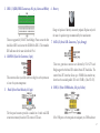


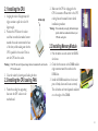
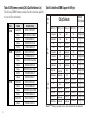
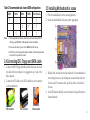
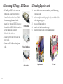
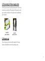
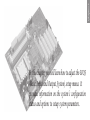
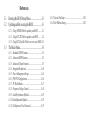

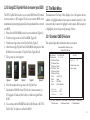
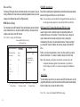


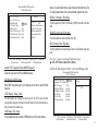

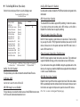
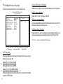
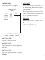
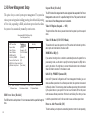
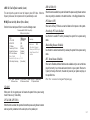
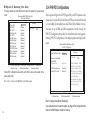

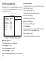


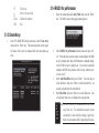
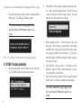
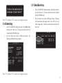
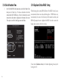


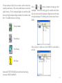
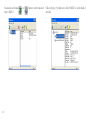


![600A01-manual-V1[1]](http://vs1.manualzilla.com/store/data/005768384_1-b36f8a87433f2b6e700f051b34ad2f22-150x150.png)