1
MICRO 3 C PLC User’s Manual
SAFETY PRECAUTIONS
• Read this user’s manual to make sure of correct operation before starting installation, wiring, operation, maintenance, and
inspection of the MICRO3C.
• All MICRO3C’s are manufactured under IDEC’s rigorous quality control system, but users must add a backup or failsafe
provision to the control system using the MICRO3C in applications where heavy damage or personal injury may be caused in
case the MICRO3C should fail.
• In this user’s manual, safety precautions are categorized in order of importance to Warning and Caution:
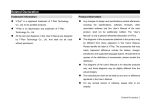
Warning
Warning notices are used to emphasize that improper operation may cause
severe personal injury or death.
Caution
Caution notices are used where inattention might cause personal injury or
damage to equipment.
Warning
• Turn power off to the MICRO3C before starting installation, removal, wiring, maintenance, and inspection on the MICRO3C.
Failure to turn power off may cause electrical shocks or fire hazard.
• Special expertise is required to install, wire, program, and operate the MICRO3C. People without such expertise must not use
the MICRO3C.
• Emergency and interlocking circuits must be configured outside the MICRO3C. If such a circuit is configured inside the
MICRO3C, failure of the MICRO3C may cause disorder of the control system, damage, or accidents.
Caution
• Install the MICRO3C according to instructions described in this user’s manual and the MICRO3 user’s manual. Improper
installation will result in falling, failure, or malfunction of the MICRO3C.
• MICRO3C is designed for installation in equipment. Do not install the MICRO3C outside of equipment.
• Install the MICRO3C in environments described in this user’s manual and the MICRO3 user’s manual. If the MICRO3C is used
in places where the MICRO3C is subjected to high-temperature, high-humidity, condensation, corrosive gases, excessive
vibrations, and excessive shocks, then electrical shocks, fire hazard, or malfunction will result.
• MICRO3C is designed for use in “Pollution degree 2.” Use the MICRO3C in environments of pollution degree 2 (according to
IEC664-1).
• All DC power type MICRO3C units are “PS2” type (according to EN61131).
• Prevent the MICRO3C from falling while moving or transporting the MICRO3C, otherwise damage or malfunction of the
MICRO3C will result.
• Prevent metal fragments and pieces of wire from dropping inside the MICRO3C housing. Put a cover on the MICRO3C during
installation and wiring. Ingress of such fragments and chips may cause fire hazard, damage, or malfunction.
• Use a power supply of the rated value. Use of a wrong power supply may cause fire hazard.
• Use wires of a proper size to meet voltage and current requirements. Tighten M3 terminal screws to a proper tightening
torque of 0.3 to 0.5 N-m.
• Use an IEC127-approved fuse (2A maximum) on the power line outside the MICRO3C. This is required when exporting
equipment containing MICRO3C to Europe.
• Use an IEC127-approved fuse on the output circuit. This is required when exporting equipment containing MICRO3C to
Europe.
• Use an EU-approved circuit breaker. This is required when exporting equipment containing MICRO3C to Europe.
• Make sure of safety before starting and stopping the MICRO3C or when operating the MICRO3C to force outputs on or off.
Incorrect operation on the MICRO3C may cause machine damage or accidents.
• If relays in the MICRO3C output circuit fail, outputs may remain on or off. For output signals which may cause heavy accidents, provide a monitor circuit outside of the MICRO3C.
• Do not connect to the ground directly from the MICRO3C. Connect a protective ground to the equipment containing
MICRO3C using an M4 or larger screw. This is required when exporting equipment containing MICRO3C to Europe.
• Do not disassemble, repair, or modify the MICRO3C.
• When the battery in the MICRO3C is dead, dispose of the battery in accordance with pertaining regulations. When taking
back the dead battery to the store or disposing of the dead battery, use a proper container installed for that purpose. This is
required when exporting equipment containing MICRO3C to Europe.
• When disposing of the MICRO3C, do so as an industrial waste.
• When the battery in the memory card is dead, dispose of the battery in accordance with pertaining regulations.
USER’S MANUAL
PREFACE-1
MICRO3C USER’S MANUAL
This user’s manual primarily describes MICRO3C’s additional functions not included in the MICRO3 programmable controllers. For installation instructions, general specifications, and common functions shared with the MICRO3 such as basic and
advanced instructions, allocation numbers, and FUN settings, see the MICRO3 user’s manual.
MICRO3C and MICRO3 Comparison
MICRO3C
PLC
40
(TXD, RXD, CMP2 added; ANR1 deleted)
500 points
32 points
Advanced Instructions
Data Registers
Standard Processing
High-speed Processing
Analog Potentiometers
Loader Port
Communication
Specifications
Data Link
Terminal
1 point
Standards
Standards
Baud Rate
EIA RS232C
EIA RS485
Expansion/data link communication:
19,200 bps (fixed)
Loader protocol communication:
9,600 bps (fixed)
Weight (approx.)
380g (16 I/O type)
430g (24 I/O type)
Standards
EN55011 Group 1, Class A
EN50082-2
UL508, CSA C22.2, No. 142
EN61131-1, EN61131-2, EN60204-1
Certification File No.
TÜV Product Service B950913332
UL E102542
CSA LR66809
MICRO3
38
100 points
32 points
1 point (10 I/O type)
2 points (16/24 I/O types)
EIA RS485
EIA RS485
Expansion/data link communication:
19,200 bps (fixed)
290g (10 I/O type)
350g (16 I/O type)
390g (16 I/O AC input type)
400g (24 I/O type)
EN61131-1, EN61131-2, EN60204-1
IEC801-2, -3, -4
PrEN50082-2, EN55011
UL508, CSA C22.2, No. 142
TÜV Product Service E9 95 09 13332
313
UL E102542
CSA LR66809
Program Loader for MICRO3C
To use the expanded capabilities of the MICRO3C such as new advanced instructions for communication and comparison
and increased data registers, use an upgraded program loader of version 2.00 or later. To check the program loader version,
read FUN31 (program loader version readout/hardware check) using the FUN31 and keys on the program loader.
To edit user programs for MICRO3C, read FUN11 (program capacity and PLC type selection) on the program loader, and
set the fourth line in the FUN11 screen to 1 to select MICRO3C as the PLC type, using the FUN11, , , , 1, and keys.
Since the loader port on the MICRO3C uses RS232C communication while the loader port on the MICRO3 uses RS485, a different loader cable is needed to connect the program loader to MICRO3C or MICRO3. Use loader cable 3C (FC2A-KL3C) to
connect a program loader to the MICRO3C loader port. A program loader can also be connected to the data link terminals on
the MICRO3C using loader cable 4C (FC2A-KL4C). In either case, loader protocol must be selected for the loader port or
data link terminals using the protocol selector switch. For selection of the protocol selector switch, see page 1-2.
Note: The upgraded program loader of version 2.00 or later can also be connected to the MICRO3 using MICRO3 loader
cable FC2A-KL1 or FC2A-KL2.
IMPORTANT INFORMATION
Under no circumstances shall IDEC Corporation be held liable or responsible for indirect or consequential damages resulting
from the use of or the application of IDEC PLC components, individually or in combination with other equipment.
All persons using these components must be willing to accept responsibility for choosing the correct component to suit their application and for choosing an application appropriate for the component, individually or in combination with other equipment.
All diagrams and examples in this manual are for illustrative purposes only. In no way does including these diagrams and
examples in this manual constitute a guarantee as to their suitability for any specific application. To test and approve all programs, prior to installation, is the responsibility of the end user.
PREFACE-2
USER’S MANUAL
TABLE OF CONTENTS
CHAPTER 1:
GENERAL INFORMATION
Features . . . . . . . . . . . . . . . . . . . . . . . . . . . . . . . . . . . . . . . . . . . . . . . . . . . . . . . 1-1
Parts Description . . . . . . . . . . . . . . . . . . . . . . . . . . . . . . . . . . . . . . . . . . . . . . . . . 1-1
System Setup . . . . . . . . . . . . . . . . . . . . . . . . . . . . . . . . . . . . . . . . . . . . . . . . . . . 1-3
Communication Specifications . . . . . . . . . . . . . . . . . . . . . . . . . . . . . . . . . . . . . . . 1-8
Dimensions . . . . . . . . . . . . . . . . . . . . . . . . . . . . . . . . . . . . . . . . . . . . . . . . . . . 1-10
CHAPTER 2:
ALLOCATION NUMBERS
Allocation Numbers . . . . . . . . . . . . . . . . . . . . . . . . . . . . . . . . . . . . . . . . . . . . . . .
I/O Allocation Numbers for Expansion Link System . . . . . . . . . . . . . . . . . . . . . . . .
Special Internal Relays . . . . . . . . . . . . . . . . . . . . . . . . . . . . . . . . . . . . . . . . . . . .
Data Register Allocation Numbers . . . . . . . . . . . . . . . . . . . . . . . . . . . . . . . . . . . .
Expansion Control Data Registers . . . . . . . . . . . . . . . . . . . . . . . . . . . . . . . . . . . . .
2-1
2-2
2-3
2-4
2-4
CHAPTER 3:
COMMUNICATION MONITOR
System Setup . . . . . . . . . . . . . . . . . . . . . . . . . . . . . . . . . . . . . . . . . . . . . . . . . . . 3-1
FUN29: User Communication Status Readout . . . . . . . . . . . . . . . . . . . . . . . . . . . . 3-1
FUN50: User Communication Data Monitor . . . . . . . . . . . . . . . . . . . . . . . . . . . . . . 3-2
CHAPTER 4:
MODEM MODE
System Setup . . . . . . . . . . . . . . . . . . . . . . . . . . . . . . . . . . . . . . . . . . . . . . . . . . . 4-1
Applicable Modems . . . . . . . . . . . . . . . . . . . . . . . . . . . . . . . . . . . . . . . . . . . . . . . 4-1
Internal Relays for Modem Mode . . . . . . . . . . . . . . . . . . . . . . . . . . . . . . . . . . . . . 4-2
Data Registers for Modem Mode . . . . . . . . . . . . . . . . . . . . . . . . . . . . . . . . . . . . . 4-2
Originate Mode . . . . . . . . . . . . . . . . . . . . . . . . . . . . . . . . . . . . . . . . . . . . . . . . . . 4-3
Disconnect Mode . . . . . . . . . . . . . . . . . . . . . . . . . . . . . . . . . . . . . . . . . . . . . . . . 4-5
AT General Command Mode . . . . . . . . . . . . . . . . . . . . . . . . . . . . . . . . . . . . . . . . . 4-5
Answer Mode . . . . . . . . . . . . . . . . . . . . . . . . . . . . . . . . . . . . . . . . . . . . . . . . . . . 4-6
Initialization String Commands . . . . . . . . . . . . . . . . . . . . . . . . . . . . . . . . . . . . . . . 4-7
Preparation before Using Modem . . . . . . . . . . . . . . . . . . . . . . . . . . . . . . . . . . . . . 4-8
Setting Communication Parameters . . . . . . . . . . . . . . . . . . . . . . . . . . . . . . . . . . . 4-8
Programming Data Registers and Internal Relays . . . . . . . . . . . . . . . . . . . . . . . . . . 4-8
Operating Procedure . . . . . . . . . . . . . . . . . . . . . . . . . . . . . . . . . . . . . . . . . . . . . . 4-9
Sample Program for Modem Originate Mode . . . . . . . . . . . . . . . . . . . . . . . . . . . . . 4-9
Checking Modem Operation . . . . . . . . . . . . . . . . . . . . . . . . . . . . . . . . . . . . . . . . 4-10
CHAPTER 5:
USER COMMUNICATION INSTRUCTIONS
B1 TXD (Transmit) . . . . . . . . . . . . . . . . . . . . . . . . . . . . . . . . . . . . . . . . . . . . . . 5-1
B2 RXD (Receive) . . . . . . . . . . . . . . . . . . . . . . . . . . . . . . . . . . . . . . . . . . . . . . 5-8
CHAPTER 6:
COMPARISON INSTRUCTION
B3
CHAPTER 7:
CMP2 (Double-word Comparison) . . . . . . . . . . . . . . . . . . . . . . . . . . . . . . . . . 6-1
COMPUTER LINK
Computer Link 1:N Communication . . . . . . . . . . . . . . . . . . . . . . . . . . . . . . . . . . . .
Computer Link 1:N Communication Using Modems . . . . . . . . . . . . . . . . . . . . . . . .
RS232C/RS485 Converter FC2A-MD1 . . . . . . . . . . . . . . . . . . . . . . . . . . . . . . . . .
RS232C Cable HD9Z-C52 . . . . . . . . . . . . . . . . . . . . . . . . . . . . . . . . . . . . . . . . . .
AC Adapter . . . . . . . . . . . . . . . . . . . . . . . . . . . . . . . . . . . . . . . . . . . . . . . . . . . . .
USER’S MANUAL
7-1
7-2
7-3
7-4
7-4
i
TABLE OF CONTENTS
CHAPTER 8:
SAMPLE PROGRAM – USER COMMUNICATION TXD
System Setup . . . . . . . . . . . . . . . . . . . . . . . . . . . . . . . . . . . . . . . . . . . . . . . . . . .
Description of Operation . . . . . . . . . . . . . . . . . . . . . . . . . . . . . . . . . . . . . . . . . . . .
Programming Expansion Control Data Registers . . . . . . . . . . . . . . . . . . . . . . . . . . .
Setting Communication Parameters . . . . . . . . . . . . . . . . . . . . . . . . . . . . . . . . . . .
Ladder Diagram . . . . . . . . . . . . . . . . . . . . . . . . . . . . . . . . . . . . . . . . . . . . . . . . . .
CHAPTER 9:
SAMPLE PROGRAM – USER COMMUNICATION TXD & RXD
System Setup . . . . . . . . . . . . . . . . . . . . . . . . . . . . . . . . . . . . . . . . . . . . . . . . . . .
Description of Operation . . . . . . . . . . . . . . . . . . . . . . . . . . . . . . . . . . . . . . . . . . . .
Setting Communication Parameters . . . . . . . . . . . . . . . . . . . . . . . . . . . . . . . . . . .
BASIC Program Display Example . . . . . . . . . . . . . . . . . . . . . . . . . . . . . . . . . . . . . .
BASIC Program . . . . . . . . . . . . . . . . . . . . . . . . . . . . . . . . . . . . . . . . . . . . . . . . . .
Ladder Diagram . . . . . . . . . . . . . . . . . . . . . . . . . . . . . . . . . . . . . . . . . . . . . . . . . .
CHAPTER 10:
CHAPTER 11:
8-1
8-1
8-1
8-2
8-2
SAMPLE PROGRAM – MODEM COMMUNICATION
System Setup . . . . . . . . . . . . . . . . . . . . . . . . . . . . . . . . . . . . . . . . . . . . . . . . . .
Allocation Numbers (Remote Station) . . . . . . . . . . . . . . . . . . . . . . . . . . . . . . . . .
Allocation Numbers (Local Station) . . . . . . . . . . . . . . . . . . . . . . . . . . . . . . . . . . .
Description of Operation . . . . . . . . . . . . . . . . . . . . . . . . . . . . . . . . . . . . . . . . . . .
Ladder Diagram (Remote Station) . . . . . . . . . . . . . . . . . . . . . . . . . . . . . . . . . . . .
Ladder Diagram (Local Station) . . . . . . . . . . . . . . . . . . . . . . . . . . . . . . . . . . . . . .
9-1
9-1
9-2
9-2
9-3
9-4
10-1
10-2
10-3
10-3
10-4
10-6
TROUBLESHOOTING
Error Causes and Actions . . . . . . . . . . . . . . . . . . . . . . . . . . . . . . . . . . . . . . . . . . 11-1
User Communication Error . . . . . . . . . . . . . . . . . . . . . . . . . . . . . . . . . . . . . . . . . 11-2
Troubleshooting Diagrams . . . . . . . . . . . . . . . . . . . . . . . . . . . . . . . . . . . . . . . . . 11-3
APPENDIX
Type List . . . . . . . . . . . . . . . . . . . . . . . . . . . . . . . . . . . . . . . . . . . . . . . . . . . . . . . A-1
ASCII Character Code Table . . . . . . . . . . . . . . . . . . . . . . . . . . . . . . . . . . . . . . . . . A-2
INDEX
ii
USER’S MANUAL
1: GENERAL INFORMATION
Introduction
This chapter describes general information about additional functions and specifications incorporated in the MICRO3C. For
general information, functions, and specifications inherited from the MICRO3, see the MICRO3 User’s Manual.
Features
MICRO3C has upgraded functions for communications. The new functions are particularly useful for modem communica-
tion, user communication, and monitoring data communication.
User Communication Function
MICRO3C has an RS232C loader port in place of the RS485 loader port on the MICRO3. The more widely applicable
RS232C loader port can be directly connected to any equipment with an RS232C communication port.
New advanced instructions for transmitting and receiving data make it possible to set up a communication system using
various communication formats.
The user communication function can be used only in the standard processing mode, not in the high-speed processing
mode.
Increased Data Registers
Since data communication requires more data registers, MICRO3C has 500 data registers (D0 through D499) expanded
from 100 data registers in the MICRO3. All expanded data registers except D499 can be used to program instructions.
In the high-speed processing mode, available data registers are limited to 32 (D0 through D31) as with the MICRO3.
Double-word Comparison of Data Registers
Double-word comparison instruction is added to compare data in data registers. Two consecutive data registers designated
by a source operand are compared with two consecutive data registers designated by another source operand. When used
with a repeat designation, one double-word comparison instruction can execute a maximum of 31 double-word comparison operations. With a repeat designation, the results of all double-word comparisons can not only be available individually but also be ANDed; so the comparison results can be easily determined even when comparing a large quantity of data.
Parts Description
Function Selector Switch
Selects the station function in the expansion or data link system.
Analog Potentiometer
Sets the analog value for the analog timer, frequency, or pulse width
of pulse outputs.
MICRO3C has only one potentiometer while 16- and 24-I/O type
MICRO3 base units have two potentiometers.
5
6
7
Protocol Selector Switch
10
0
Selects the communication protocol for the loader port (loader protocol or user protocol) and the data link terminals (data link/expansion
link or loader protocol).
701
6
2
543
1
701
6
2
543
Loader Port
For connecting the program loader or computer. The loader port can
also be used as a user communication port when user protocol is
selected with the protocol selector switch.
Communication Enable Button
A
DATA LINK
B
SG
Enables the communication mode selected with the protocol selector
switch. When the protocol selector switch setting is changed while
the MICRO3C is powered up, press this button to enable the new communication mode for the loader port and data link terminals.
Data Link Terminals
For connecting the data link line in the expansion link or data link
system. The data link terminals can also be used for connecting the
program loader or computer when loader protocol is selected with the
protocol selector switch.
USER’S MANUAL
The figure above illustrates the 16-I/O
type MICRO3C base unit.
1-1
1: GENERAL INFORMATION
Protocol Selector Switch
The protocol selector switch is used to select communication modes for the RS232C loader port and the RS485 data link
terminals. When the MICRO3C is powered up, the selected communication modes are enabled automatically. If the protocol
selector switch setting is changed after the MICRO3C is powered up, the new setting does not take effect until the communication enable button is depressed.
Communication Protocols for Loader Port and Data Link Terminals
Protocol Selector Switch Position
0
1
2
3
4
5 through 7
Loader Port Protocol
Loader protocol
User protocol
Loader protocol
User protocol
Loader protocol
Reserved
Data Link Terminal Protocol
Data link protocol
Data link protocol
Loader protocol
Loader protocol
Loader protocol
Reserved
Remarks
For maintenance (Note 1)
(Note 2)
Loader protocol:
The protocol used for communication between MICRO3C and program loader or CUBIQ on computer.
User protocol:
The protocol used for user communication instructions (RS232C)
Data link protocol: The protocol used for communication in the expansion link or data link (RS485).
Note 1: When the protocol selector switch is set to 4, the communication parameters for the loader port are arbitrarily set
to the default values of FUN8 (loader port communication mode setting); baud rate 9,600 bps, terminator code 0D, 7 data
bits, even parity, 1 stop bit, and receive timeout 500 msec. Any change in FUN8 values does not take effect. The communication parameters for the data link terminals using the loader protocol are fixed and the same as the FUN8 default values.
Note 2: When the protocol selector switch is set to 5 through 7, the ERR1 indicator on the MICRO3C blinks and the
MICRO3C does not start to run.
Communication Enable Button
While the MICRO3C is powered up, pressing the communication enable button for more than 4 seconds until the ERR1
indicator blinks once makes the MICRO3C read the settings on the protocol selector switch and function selector switch.
Then the MICRO3C updates the communication modes for the loader port and data link terminals. This button is useful
when you want to change the communication mode without turning power off.
If the communication enable button is pressed while the MICRO3C is in operation, the user program
execution is stopped and all outputs are forced off.
Warning
Function Selector Switch
When the protocol selector switch is set to 0 or 1, the data link terminals can be used for expansion link or data link communication. Then the function selector switch selects the station function for each MICRO3C in the expansion link or data
link system. The function of the function selector switch on the MICRO3C is the same as that on the MICRO3. When the protocol selector switch is set to 2 through 4 to select loader protocol for the data link terminals, the function selector switch
setting has no effect.
MICRO3C Station Function by Function Selector Switch Position
Function Selector Switch Position
0
1
2
3
4
5
6
7
1-2
MICRO3C Station Function
Base or master station
Slave station 1
Slave station 2
Slave station 3
Slave station 4
Slave station 5
Slave station 6
Expansion station
USER’S MANUAL
1: GENERAL INFORMATION
System Setup
This section describes various system configurations using the MICRO3C and required settings.
Selecting Communication Mode
Set the function selector switch and the protocol selector switch to select a desired communication mode for the loader
port and data link terminals. After changing the settings of the function selector switch and protocol selector switch while
the MICRO3C is powered up, press the communication enable button for more than 4 seconds until the ERR1 indicator
blinks once; then the new communication mode takes effect. When the MICRO3C is powered up, the MICRO3C checks the
settings of the function selector switch and protocol selector switch and enables the selected communication mode automatically. You have to press the communication enable button only when you change the communication mode while the
MICRO3C is powered up.
Warning
If the communication enable button is pressed while the MICRO3C is in operation, the user program
execution is stopped and all outputs are forced off.
Connecting Program Loader to the Loader Port
When connecting a program loader to the loader port on the MICRO3C, set the protocol selector switch to 0, 2, or 4 to select
loader protocol for the loader port. Use the loader cable 3C to connect the program loader to the MICRO3C loader port.
Caution
Special cables are needed to connect to the loader port on the MICRO3C. Loader cables for the
MICRO3 such as FC2A-KL1 (2m/6.56 ft. long) and FC2A-KL2 (5m/16.4 ft. long) cannot be used for
the MICRO3C. Cables used for connecting to the loader port on the MICRO3C cannot be used for the
MICRO3. If a wrong cable is used, machine damage may result.
Loader Cable 3C
FC2A-KL3C (2m/6.56 ft. long)
The loader cable 3C has an
RS232C/RS485 converter in
the middle.
When connecting and disconnecting the
loader cable, be sure to hold the connector. Since the connector has a latch, the
cable cannot be removed holding the
cable.
Make sure of correct direction of the
cable as indicated on the direction labels
attached near the connectors on the cable.
Connecting the Cable
The program loader has a cover on the top to select the loader cable
connection port or AC adapter jack. Slide the cover to the right to open
the loader cable connection port.
Connect the connector of the loader cable to the loader cable connection port on the program loader and the other connector of the cable to
the loader port on the MICRO3C as indicated on the direction labels.
USER’S MANUAL
Slide the cover to the right
Loader Cable Connection Port
1-3
1: GENERAL INFORMATION
Connecting Program Loader to the Data Link Terminals
A program loader can also be connected to the data link terminals on the MICRO3C when the protocol selector switch is set
to 2, 3, or 4 to select loader protocol for the data link terminals. This capability is particularly useful to monitor the communication data transmitted through the loader port while user communication or modem communication is performed
with the protocol selector switch set to 3.
Loader Cable 4C
FC2A-KL4C (2m/6.56 ft. long)
The loader cable 4C has a power
supply box in the middle.
(RS485)
(RS485)
AC Adapter (Output: 5V DC)
The loader cable 4C is not supplied with
an AC adapter, which must be prepared
by the user.
Note: AC adapters for IDEC’s FA series
PLCs cannot be used.
Connecting the Cable
Slide the cover to the right
The program loader has a cover on the top to select the loader cable
connection port or AC adapter jack. Slide the cover to the right to
open the loader cable connection port.
Connect the connector of the loader cable to the loader cable connection port on the program loader and the three spade terminals on
the other end of the cable to the data link terminals on the MICRO3C
as indicated on the marker tubes.
Loader Cable Connection Port
Connect an AC adapter to the power supply box in the middle of the
loader cable 4C to supply power to the program loader. Applicable
output plug of the AC adapter is shown on the right.
9.5
ø5.5
Connecting an AC Adapter
ø2.1
Polarity
+
–
Dimensions in mm.
Caution
When a program loader or computer running CUBIQ is connected to the data link terminals and a
communication device is connected to the loader port at the same time to perform communications
shown below, multi-stage comparison instruction HSC1 cannot be used.
Data link terminals: Used for loader protocol communication
Loader port:
Used for loader protocol communication at 19,200 bps
1-4
USER’S MANUAL
1: GENERAL INFORMATION
Computer Link through Loader Port
To set up a 1:1 computer link system, connect an IBM PC or compatible to the MICRO3C using the computer link cable 4C
(FC2A-KC4C). Set the protocol selector switch to 0, 2, or 4 to select loader protocol for the loader port.
Computer Link Cable 4C
To RS232C Port
FC2A-KC4C
3m (9.84 ft.) long
To Loader Port
(RS232C)
D-sub 9-pin
Female Connector
Cable Connector Pinouts
Pin
1
2
3
4
5
6
7
8
9
DCD
RXD
TXD
DTR
GND
DSR
—
CTS
—
Description
Data Carrier Detect
Receive Data
Transmit Data
Data Terminal Ready
Signal Ground
Data Set Ready
—
Clear to Send
—
Computer Link through Data Link Terminals
A 1:1 computer link system can also be set up through the data link terminals on the MICRO3C using the computer link
cable 6C (FC2A-KC6C). Set the protocol selector switch to 2, 3, or 4 to select loader protocol for the data link terminals.
Computer Link Cable 6C
FC2A-KC6C
2m (6.56 ft.) long
To RS232C Port
RS232C/RS485
Converter
D-sub 9-pin
Female Connector
A B SG
Cable Connector Pinouts
(RS485)
B
SG
A
Connect the three spade terminals on the computer link
cable 6C to data link terminals A, B, and SG as indicated on the maker tubes.
AC Adapter
Output: 5V DC
Connect an AC adapter to the RS232C/RS485 converter in the
middle of the computer link cable 6C.
The computer link cable 6C is not supplied with an AC adapter,
which must be prepared by the user.
For applicable output plug of the AC adapter, see page 1-4.
Note: AC adapters for IDEC’s FA series PLCs cannot be used.
USER’S MANUAL
Pin
1
2
3
4
5
6
7
8
9
—
RXD
TXD
—
GND
—
RTS
CTS
—
Description
—
Receive Data
Transmit Data
—
Signal Ground
—
Request to Send
Clear to Send
—
1-5
1: GENERAL INFORMATION
Connecting Modem through Loader Port
To connect a modem to the loader port on the MICRO3C, use the modem cable 1C (FC2A-KM1C). Set the protocol selector
switch to 1 or 3 to select user protocol for the loader port.
Modem Cable 1C
To RS232C Port
FC2A-KM1C
3m (9.84 ft.) long
Modem
To Loader Port
(RS232C)
D-sub 25-pin
Male Connector
Cable Connector Pinouts
Pin
1
2
3
4
5
6
7
8
20
FG
TXD
RXD
RTS
—
—
SG
DCD
DTR
Description
Frame Ground
Transmit Data
Receive Data
Request to Send
—
—
Signal Ground
Data Carrier Detect
Data Terminal Ready
Connecting RS232C Equipment through Loader Port
To connect equipment with an RS232C communication port to the loader port on the MICRO3C, use the user communication cable 1C (FC2A-KP1C). One end of the user communication cable 1C is not provided with a connector, and it can be
terminated with a proper connector to plug in to communicate with the RS232C port.
When the protocol selector switch is set to 1 or 3, MICRO3C can communicate with RS232C equipment through the loader
port using the user protocol. When the protocol selector switch is set to 0, 2, or 4, MICRO3C can communicate through the
loader port using the loader protocol.
RS232C Equipment
User Communication Cable 1C
FC2A-KP1C
2.4m (7.87 ft.) long
To Loader Port
(RS232C)
To RS232C Port
Attach a proper connector to the
open end referring to the cable
connector pinouts shown below.
Cable Connector Pinouts
Pin
1
2
3
4
5
6
7
8
Cover
1-6
RTS
DTR
TXD
RXD
DSR
SG
SG
NC
—
Description
Request to Send
Data Terminal Ready
Transmit Data
Receive Data
Data Set Ready
Signal Ground
Signal Ground
No Connection
Shield
USER’S MANUAL
AWG#
28
28
28
28
28
28
26
26
Twisted
Twisted
—
Color
Black
Yellow
Blue
Green
Brown
Gray
Red
White
—
Signal Direction
1: GENERAL INFORMATION
Link Systems
MICRO3C has three link functions; expansion link, data link, and computer link. When using a link function, the function
selector switch and protocol selector switch have to be set and the FUN settings may be required. For details of these settings, see Expansion Link Function and Data Link Function in the MICRO3 User’s Manual and Computer Link 1:N Communication on page 7-1 in this manual. The expansion link cannot be used in the data link system.
Expansion Link System
The expansion link system consists of two MICRO3C or MICRO3 base units connected through the data link terminals using
the optional expansion cable FC2A-KE1 (250 mm/9.84" long) or a shielded twisted pair cable as shown below. The cable
for the expansion link system can be extended up to 200 meters (656 feet). Every MICRO3C or MICRO3 base unit can be
used as an expansion station.
Base Station
Expansion Station
Function selector switch: 0
Protocol selector switch: 0 or 1
Function selector switch: 7
Protocol selector switch: 0 or 1
The RUN indicator on the expansion station remains off whether the
base station is running or stopped.
Data Link System
The data link system consists of one master station connected to a maximum of six slave stations to communicate control
data for distributed control. Every MICRO3C or MICRO3 base unit can be used as a master or slave station. When a slave station performs communication at 19,200 bps through the loader port, multi-stage comparison instruction HSC1 cannot be
used at the slave station.
Master Station
Slave Station 1
Slave Station 2
Slave Station 6
Function selector switch: 0
Protocol selector switch: 0 or 1
Function selector switch: 1
Protocol selector switch: 0 or 1
Function selector switch: 2
Protocol selector switch: 0 or 1
Function selector switch: 6
Protocol selector switch: 0 or 1
Computer Link System
In the computer link system, a personal computer is connected to one or a maximum of 32 MICRO3C base units to control
the operation of all MICRO3C base units. The 1:1 computer link system requires the computer link cable 4C (FC2A-KC4C)
or computer link cable 6C (FC2A-KC6C). The 1:N computer link system using MICRO3C base units requires RS232C/
RS485 converter FC2A-MD1 and cables; computer link interface unit FC2A-LC1 is not required.
1st Unit
2nd Unit
Nth Unit (N ≤ 32)
Function selector switch: 0
Protocol selector switch: 2, 3, or4
FUN9: 0
Function selector switch: 0
Protocol selector switch: 2, 3, or 4
FUN9: 1
Function selector switch: 0
Protocol selector switch: 2, 3, or 4
FUN9: N–1
RS232C/RS485
Converter
FC2A-MD1
The figure above illustrates a 1:N computer link system for MICRO3C.
USER’S MANUAL
1-7
1: GENERAL INFORMATION
Communication Specifications
This section describes the MICRO3C communication specifications. For general specifications, function specifications, I/O
specifications, and program loader specifications, see the MICRO3 User’s Manual.
Loader Port Communication Specifications
Standards
Maximum Cable Length
Baud Rate
Data Bits
Parity
Communication
Stop Bits
Parameters
Receive Timeout
Connection to Program Loader
Connection to RS232C Equipment
EIA RS232C
15m (49.2 ft.)
1200, 2400, 4800, 9600, 19200 bps
7 or 8 bits
Odd, Even, None
1 or 2 bits
10 to 2550 msec
(In the user communication, receive timeout is disabled when 2550 msec is
selected.)
Using optional loader cable 3C (FC2A-KL3C)
Using optional user communication cable 1C (FC2A-KP1C) or other cables
User Communication Mode Specifications
When the protocol selector switch is set to 1 or 3 to select user protocol for the loader port, the MICRO3C can communicate
through the loader port with external equipment which has an RS232C port, such as a computer, modem, printer, or barcode reader.
Using transmit and receive instructions for user communication, user programs can be created to match the communication protocol of the equipment to communicate with. Determine the possibility of communication referring to the user
communication mode specifications described below:
Standards
Control Signal
Baud Rate
Data Bits
Parity
Stop Bits
Receive Timeout
Communication Method
Maximum Transmit Data
Maximum Receive Data
1-8
EIA RS232C
TXD, RXD, DTR, RTS, DSR
1200, 2400, 4800, 9600, 19200 bps
7 or 8 bits
Odd, Even, None
1 or 2 bits
10 to 2550 msec (10-msec increments) or none
(Receive timeout is disabled when 2550 msec is selected.)
Start-stop synchronization system half-duplex
200 bytes
200 bytes
USER’S MANUAL
1: GENERAL INFORMATION
Data Link Terminal Communication Specifications
Standards
Recommended Cable
Conductor Resistance
Shield Resistance
Maximum Cable Length
EIA RS485 (termination resistor is not required)
ø0.9 mm shielded twisted cable
85 Ω/km maximum
12 Ω/km maximum
200m (656 ft.)
Isolation
Between data link terminals of multiple MICRO3C units: Not isolated
Expansion or data link communication:
19200 bps (fixed)
Loader protocol communication:
9600 bps (fixed)
Expansion link: Master station normal scan time + approx. 9 to 10 msec
Data link:
Master station normal scan time + approx. 12.5 to 13 msec + Slave
station scan time
Using optional loader cable 4C (FC2A-KL4C)
Baud Rate
Communication Delay
Connection to Program Loader
Data Link Terminal Communication with Program Loader
When the protocol selector switch is set to 2, 3, or 4 to select loader protocol for the data link terminals, the MICRO3C can
communicate through the data link terminals with the program loader or computer to monitor the MICRO3C operation,
transfer user programs, and perform other communications. The communication parameters using the loader protocol for
the data link terminals are fixed to the same values as the FUN8 (loader port communication mode setting) default shown
below and cannot be selected unlike the communication through the loader port.
Data Link Terminal Communication Parameters (Loader Protocol)
Baud Rate
Terminator Code
Data Bits
Parity
Stop Bit
Receive Timeout
9600 bps
0D (CR)
7 bits
Even
1 bit
500 msec
When the protocol selector switch is set to 2 or 4, the MICRO3C can perform loader communication through both the loader
port and data link terminals at the same time. If data write operation (write N bytes or write 1 bit) is attempted to the same
operand through both the loader port and data link terminals at the same time, the command through the data link terminals has priority although communication error does not occur at both ports.
Caution
Some of the program transfer operation cannot be performed as described below:
1. While a user program is written through either the loader port or data link terminals, a user program cannot be written
through the other port.
The prior write user program operation is executed normally, but the subsequent write user program operation results
in a protect error.
2. While a user program is written through either the loader port or data link terminals, a user program cannot be read
through the other port.
The prior write user program operation is executed normally, but the subsequent read user program operation results in
a protect error.
3. A user program cannot be read through either the loader port or data link terminals if a user program is written through
the other port before the read user program operation is completed.
The subsequent write user program operation is executed normally, but the prior read user program operation may fail
to read the complete user program and result in a CRC error.
USER’S MANUAL
1-9
1: GENERAL INFORMATION
Dimensions
MICRO3C Base Unit
85 mm (3.346")
Program Loader
16-I/O Type: 135 mm (5.315")
24-I/O Type: 165 mm (6.496")
60 mm (2.362")
80 mm (3.150")
Mounting Hole Layout
Minimum
center to center
58 mm (2.283")
M4 tapped holes or
ø4.5 (0.177" dia.) drilled holes
77 mm
(3.031")
16-I/O Type: 116 mm (4.567")
24-I/O Type: 146 mm (5.748")
1-10
Minimum center to center
29 mm (1.142")
USER’S MANUAL
30 mm
(1.181")
185 mm (7.283")
95 mm (3.740")
25 mm
(0.984")
2: ALLOCATION NUMBERS
Introduction
This chapter describes allocation numbers available only for the MICRO3C. For details about allocation numbers shared
with the MICRO3, see the MICRO3 User’s Manual.
Expanded functions in the MICRO3C include:
MICRO3C has 500 data registers D0 through D499 while MICRO3 has 100 data registers D0 through D99. D499 is used to
enable or disable expansion control data registers D484 through D498 and cannot be used as an ordinary data register to
store data.
Special internal relay M307 has different functions when used as a base or expansion station in the expansion link system
or when used as a master station or slave station in the data link system.
Allocation Numbers
Available I/O numbers depend on the type and combination of the MICRO3C base units used in the expansion link system.
For details of available I/O numbers in the expansion link system, see the next page.
Operand
Input
Output
Processing Mode
Standard and
High-speed
Standard only
Standard and
High-speed
Standard only
Standard and
High-speed
Internal Relay
Standard only
Allocation Number
I0 - I7
I10 - I15
I20 - I27
I30 - I35
Q0 - Q7
Q10 - Q11
Q20 - Q27
M0 - M7
M30 - M37
M50 - M57
M80 - M87
M110 - M117
M140 - M147
M170 - M177
M200 - M207
M230 - M237
M260 - M267
Q30 - Q31
M10 - M17
M40 - M47
M60 - M67
M90 - M97
M120 - M127
M150 - M157
M180 - M187
M210 - M217
M240 - M247
M270 - M277
Catch Input Relay
Standard and
High-speed
M290 - M297
Special Internal
Relay
Standard and
High-speed
M300 - M307
Timer
Standard and
High-speed
T0 - T15
Counter
Shift Register
Data Register
Standard only
Standard and
High-speed
Standard only
Standard and
High-speed
Standard only
Standard and
High-speed
Standard only
Maximum Points
14 points (Base)
+
14 points (Expansion)
10 points (Base)
+
10 points (Expansion)
M20 - M27
M70 - M77
M100 - M107
M130 - M137
M160 - M167
M190 - M197
M220 - M227
M250 - M257
M280 - M287
232 points
(40 points)
8 points
(8 points)
M310 - M317
T16 - T31
C0 - C15
16 points
(16 points)
32 points total
(16 points total)
C16 - C31
R0 - R31
R32 - R63
D0 - D31
D32 - D499
64 points
(32 points)
500 points
(32 points)
Notes: Input and output allocation numbers for the expansion station start with I20 and Q20. For the I/O allocation numbers in the expansion link system, see the next page.
The maximum points shown in ( ) are values for the high-speed processing mode.
The same number cannot be used for a counter and a timer in a user program.
Internal relays M260 through M287 have special functions in the modem mode. See page 4-2.
Data register D499 is reserved to enable or disable expansion control data registers D484 through D498 and cannot be
used as an ordinary data register to store data. For details, see page 2-4.
USER’S MANUAL
2-1
2: ALLOCATION NUMBERS
I/O Allocation Numbers for Expansion Link System
Input and output allocation numbers do not continue from the base station to the expansion station. At the expansion station, inputs start at I20 and outputs start at Q20. Inputs and outputs are allocated depending on the MICRO3C base units
used in the expansion link system as shown below:
I/O Points
Total
IN/OUT
16
9/7
24
14/10
32
18/14
40
48
2-2
23/17
28/20
MICRO3C Base Station
I/O Allocation Numbers
16-I/O Type
I0 - I7
Q0 - Q6
I10
24-I/O Type
I0 - I7
Q0 - Q7
I10 - I15
Q10 - Q11
16-I/O Type
I0 - I7
Q0 - Q6
I10
16-I/O Type
I0 - I7
Q0 - Q6
I10
24-I/O Type
I0 - I7
Q0 - Q7
I10 - I15
Q10 - Q11
24-I/O Type
I0 - I7
Q0 - Q7
I10 - I15
Q10 - Q11
USER’S MANUAL
MICRO3C Expansion Station
I/O Allocation Numbers
———
———
16-I/O Type
I20 - I27
I30
Q20 - Q26
24-I/O Type
I20 - I27
I30 - I35
Q20 - Q27
Q30 - Q31
16-I/O Type
I20 - I27
I30
Q20 - Q26
24-I/O Type
I20 - I27
I30 - I35
Q20 - Q27
Q30 - Q31
2: ALLOCATION NUMBERS
Special Internal Relays
Internal relays M290 through M317 are special internal relays with the following functions:
Allocation Number
Description
CPU Stopped
Power OFF
M290
Input I0
Operating
Cleared
M291
Input I1
Operating
Cleared
M292
Input I2
Operating
Cleared
M293
Input I3
Operating
Cleared
Input I4
Operating
Cleared
M295
Input I5
Operating
Cleared
M296
Input I6
Operating
Cleared
M297
Input I7
Operating
Cleared
M294
Catch Input Status Set
(See Note below)
M300
Start Control
Maintained
Maintained
M301
Initialize Pulse (See Note below)
Cleared
Cleared
M302
All Outputs OFF
Cleared
Cleared
M303
Carry (Cy) or Borrow (Bw)
Cleared
Cleared
M304
User Program Execution Error
Cleared
Cleared
M305
Link Communication Error
(Expansion mode and data link mode)
Maintained
Cleared
M306
Link Communication Prohibit Flag
(Expansion mode and data link mode)
Maintained
Maintained
Cleared
Cleared
M307
Link Communication Initialize Flag (Master Station)
(Expansion mode and data link mode)
Link Communication Stop Flag (Slave Station)
(Data link mode)
M310
1-sec Clock Reset
Cleared
Cleared
M311
1-sec Clock
Operating
Cleared
M312
100-msec Clock
Operating
Cleared
M313
10-msec Clock
Operating
Cleared
M314
Timer/Counter Preset Value Changed
Maintained
Maintained
M315
High-speed Counter Soft Reset
Maintained
Cleared
M316
High-speed Counter (HSC3) Overflow
Cleared
Cleared
M317
In-operation Output
Cleared
Cleared
Note: M290 through M297 and M301 are used only for reading in the user program, but can be directly set or reset using
the program loader or optional software CUBIQ on a computer.
M307 Link Communication Initialize Flag (Master Station)/Link Communication Stop Flag (Slave Station)
Special internal relay M307 has different functions when used as a base or expansion station in the expansion link system
or when used as a master station or slave station in the data link system.
Base or master station: Link communication initialize flag
When M307 at the base or master station is turned on during operation, the link configuration is checked to initialize the
expansion or data link system. When an expansion station or slave station is powered up after the base or master station,
turn M307 on to initialize the link system. After an expansion link or data link setup is changed, M307 must also be turned
on to ensure correct communication.
Slave station: Link communication stop flag
When a slave station does not receive communication data from the master station for 800 msec or more in the data link
system, M307 turns on. When the slave station receives correct communication data, M307 turns off.
In the expansion station, M307 has no effect and cannot be monitored using the program loader.
USER’S MANUAL
2-3
2: ALLOCATION NUMBERS
Data Register Allocation Numbers
Available data registers are limited in the high-speed processing mode or in the data link system configuration. Some data
registers are allocated to special functions in the data link system as shown below. For the data link function, see the
MICRO3 User’s Manual. D100 through D209, D492, and D493 have special functions in the modem mode. See page 4-2.
Data Register
Number
Standard Processing Mode
D0 to D31
D32 to D59
D60 to D84
Available
Available
For data link
D85 to D89
D90 to D99
Data Link
(Master Station)
Other than Data Link
Data Link
(Slave Station)
Available
Available
For data link
Can be designated as control data registers using FUN10. (Note)
D100 to D483
Available
D484 to D485
When expansion control data register service is enabled for each group of these
data registers using D499, the selected data registers work as expansion control data registers; others can be used as ordinary data registers.
When expansion control data register service is disabled using D499, these
data registers can be used as ordinary data registers.
D486 to D491
D492 to D495
D496 to D498
D499
High-speed
Processing Mode
Not available
Reserved to enable or disable expansion control data register service.
Note: When FUN10 is set to enable control data registers, selected data registers D90 through D99 work as control data
registers; others can be used as ordinary data registers. For details of the data link function, see the MICRO3 User’s Manual.
Expansion Control Data Registers
Data registers D484 through D499 are allocated as expansion control data registers. D499 is used to enable or disable
expansion control data register service for D484 through D498 divided into group 0 through 3. Data registers in the group
disabled for expansion control data registers can be used as ordinary data registers.
D499 cannot be used as an ordinary data register and must not be programmed to store data of operation results.
Group
Expansion Control DR
—
D499
Expansion control data register service selection
D498
Day (Calendar)
D497
Month (Calendar)
D496
Year (Calendar)
D495
Modem mode selection
D494
Reserved
D493
Modem mode status
D492
Protocol selection in modem mode
D491
Control signal status
D490
DSR control signal option
D489
DTR control signal option
D488
RTS control signal option
D487
Reserved
D486
RTS control signal ON/OFF timer
0
1
2
3
2-4
Description
D485 (Lower byte)
Protocol selector switch value
D485 (Upper byte)
For maintenance
D484 (Lower byte)
Function selector switch value
D484 (Upper byte)
For maintenance
USER’S MANUAL
Available only for communication through
the loader port using user protocol
(protocol selector switch set to 1 or 3)
2: ALLOCATION NUMBERS
D499 Expansion Control Data Register Service Selection
D499 is used to enable or disable expansion control data register service for D484 through D498 divided into group 0
through 3.
D499 cannot be used as an ordinary data register and must not be programmed to store data of operation results. If an unexpected value is set to D499, the modem mode may be enabled or disabled
during operation.
Warning
Store a value in D499 to enable or disable expansion control data service for group 0 through 3 as described below:
Group
0
1
2
3
0
1
2
3
4
5
6
D499 Value
7
8
9
10
11
12
13
14
15
(D496-D498)
(D492-D495)
(D486-D491)
(D484-D485)
The D499 value marked with indicates that the data registers in the corresponding group are enabled for expansion control data register service. The enable/disable of expansion control data register service is determined by the lower 4 bits in
D499. Although a value over 15 can be entered to D499, upper 12 bits do not take effect.
Group 0
D498 Day (Calendar)
D497 Month (Calendar)
D496 Year (Calendar)
When group 0 is enabled as expansion control data registers, the calendar data are stored to D496 through D498. The year
is indicated with the lower 2 digits.
Group 1
D495 Modem mode selection
When group 1 is enabled as expansion control data registers and “1” is set to D495, the modem mode is enabled. When
“0” is set to D495, the modem mode is disabled. For the modem mode, see page 4-1.
D494 Reserved
D493 Modem mode status
When the modem mode is enabled (see above), D493 stores a modem mode status.
D493 Value
30h
31h
Description
AT command completed normally
Issuing AT command
32h
AT command execution error
33h
34h
Two or more start IRs are on
Modem mode enabled
35h
Start IR program error
36h
37h
38h
39h
(Reserved)
(Reserved)
Retrying AT command
AT command program error
Remarks
AT command (start IR) is completed normally.
See the result code stored in data registers D104 through D119.
Check the modem power, modem cable, and the remote modem.
Correct the program so that only one start IR goes on at a time.
Correct the program so that only the disconnect command is issued
while the line is connected.
Correct the program to include 0Dh in the AT command.
D492 Protocol selection in modem mode
When the modem mode is enabled (see above), the protocol at the loader port is switched from the user protocol depending on the value in D492 after the telephone line is connected.
D492 = 1: User protocol is continued at the loader port
D492 = 0: Loader protocol is enabled at the loader port
USER’S MANUAL
2-5
2: ALLOCATION NUMBERS
Group 2
D491 Control signal status
When group 2 is enabled as expansion control data registers, D491 stores a value to show that RTS, DSR, and DTR are on
or off. The data of D491 is updated at every END processing.
D491 Value
0
1
2
3
4
5
6
7
RTS
OFF
ON
OFF
ON
OFF
ON
OFF
ON
DSR
OFF
OFF
ON
ON
OFF
OFF
ON
ON
DTR
OFF
OFF
OFF
OFF
ON
ON
ON
ON
Description
All RTS, DSR, and DTR are off.
RTS is on.
DSR is on.
RTS and DSR are on.
DTR is on.
RTS and DTR are on.
DSR and DTR are on.
All RTS, DSR, and DTR are on.
D490 DSR control signal option
When group 2 is enabled as expansion control data registers, D490 is used to control data flow between the MICRO3C and
the remote terminal depending on the DSR (Data Set Ready) signal of the remote terminal. The DSR signal is an input to
the MICRO3C to determine the status of the remote terminal. The remote terminal informs the MICRO3C using DSR whether
the remote terminal is ready for receiving data or is sending valid data.
The DSR control signal option can be used only in the user protocol to communicate through the loader port.
D490 = 0 (system default):
DSR is not used for data flow control. When DSR control is not needed, set 0 to D490.
D490 = 1: When DSR is on, MICRO3C can transmit and receive data.
DSR signal
ON
OFF
Transmit/receive
Impossible
Possible
Impossible
Data
Transmit/receive data
D490 = 2: When DSR is off, MICRO3C can transmit and receive data.
DSR signal
ON
OFF
Transmit/receive
Impossible
Possible
Impossible
Data
Transmit/receive data
D490 = 3: When DSR is on, MICRO3C can transmit data. This function is usually called “Busy Control” and is used for
controlling transmission to a remote terminal with a slow processing speed, such as a printer. When the remote
terminal is busy, data input to the remote terminal is restricted.
DSR signal
ON
OFF
Transmit
Transmit data
2-6
Impossible
Possible
Data
USER’S MANUAL
Impossible
2: ALLOCATION NUMBERS
D490 = 4: When DSR is off, MICRO3C can transmit data. This function is contrary to “D490 = 3.”
DSR signal
ON
OFF
Transmit
Impossible
Possible
Impossible
Data
Transmit data
D490 = 5: When DSR is on, MICRO3C can receive data.
DSR signal
ON
OFF
Data
Receive data
MICRO3C receives data arriving while DSR is on.
Data out of this range are not received.
D490 = 6: When DSR is off, MICRO3C can receive data. This function is contrary to “D490 = 5.”
DSR signal
ON
OFF
Data
Receive data
MICRO3C receives data arriving while DSR is off.
Data out of this range are not received.
D490 = 7 or more: Same as D490 = 0. DSR is not used for data flow control.
D489 DTR control signal option
When group 2 is enabled as expansion control data registers, D489 is used to control the DTR (Data Terminal Ready) signal to indicate the MICRO3C operating status or transmitting/receiving status.
The DTR control signal option can be used only in the user protocol to communicate through the loader port.
D489 = 0 (system default):
While MICRO3C is running, DTR is on whether MICRO3 is transmitting or receiving data. While MICRO3C is
stopped, DTR remains off. Use this option to indicate the MICRO3C operating status.
MICRO3C
DTR signal
Stopped
Running
Stopped
ON
OFF
D489 = 1: While MICRO3C is transmitting data, DTR is turned on. While MICRO3C is not transmitting data, DTR remains
off. Use this option when a remote terminal operates in the half-duplex mode since DTR goes on or off
according to the transmit data from MICRO3C.
Transmit data
DTR signal
Transmit data
ON
OFF
USER’S MANUAL
2-7
2: ALLOCATION NUMBERS
D489 = 2: While MICRO3C is transmitting data, DTR remains off. While MICRO3C is not transmitting data, DTR is turned
on. The DTR operation at this option is contrary to the operation at D489 = 1.
Transmit data
Transmit data
DTR signal
ON
OFF
D489 = 3: DTR remains off.
D489 = 4: While MICRO3C can receive data, DTR is turned on. Use this option when flow control of receive data is
required.
D489 = 5: DTR is turned on or off according to DSR. When DSR is on, DTR is turned on. When DSR is off, DTR
remains off. Use this option for returning control signal and acknowledgment when data flow control with the
remote terminal is required.
DSR signal
DTR signal
ON
OFF
ON
OFF
D489 = 6 or more: Same as D489 = 0.
D488 RTS control signal option
When group 2 is enabled as expansion control data registers, D488 is used to control the RTS (Request to Send) signal to
indicate the MICRO3C transmitting/receiving status or operating status.
The RTS control signal option can be used only in the user protocol to communicate through the loader port.
D488 = 0 (system default):
While MICRO3C is transmitting data, RTS remains off. While MICRO3C is not transmitting data, RTS is turned
on. Use this option when a remote terminal operates in the half-duplex mode since RTS goes on or off according to the transmit data from MICRO3C.
Transmit data
Transmit data
RTS signal
ON
OFF
D488 = 1: While MICRO3C is transmitting data, RTS is turned on. While MICRO3C is not transmitting data, RTS remains
off. Use this option when a remote terminal operates in the half-duplex mode since RTS goes on or off according to the transmit data from MICRO3C.
Transmit data
Transmit data
RTS signal
ON
OFF
D488 = 2: While MICRO3C is running, RTS is on whether MICRO3C is transmitting or receiving data. While MICRO3C is
stopped, RTS remains off. Use this option to indicate the MICRO3C operating status.
MICRO3C
RTS signal
Stopped
Running
ON
OFF
D488 = 3: RTS remains off.
2-8
USER’S MANUAL
Stopped
2: ALLOCATION NUMBERS
D488 = 4: While MICRO3C can receive data, RTS is turned on. Use this option when flow control of receive data is
required.
D488 = 5: RTS is turned on or off according to DSR. When DSR is on, RTS is turned on. When DSR is off, RTS remains
off. Use this option for returning control signal and acknowledgment when data flow control with the remote
terminal is required.
DSR signal
RTS signal
ON
OFF
ON
OFF
D488 = 6 or more: Same as D488 = 0.
D487 Reserved
D486 RTS control signal ON/OFF timer
When group 2 is enabled as expansion control data registers and D488 is set to 0 or 1 to synchronize the transmit data with
the RTS signal, D486 is used to set the amount of time to turn on and off the RTS signal before and after transmitting data.
The RTS control signal ON/OFF timer can be used only in the user protocol to communicate through the loader port.
D486 = 0 through 249 (Increments 10 msec):
Any value over 249 is regarded as 249.
The maximum timer error is 20 msec + 2 scan time.
Example: D488 = 0 (RTS control signal option) and D486 = 5
RTS signal
ON
OFF
Transmit data
Transmit data
50 msec
50 msec
MICRO3C transmits data 50 msec after RTS is turned off and RTS is turned on 50 msec after data transmission
is completed.
Since a sufficient amount of time is allowed for the remote terminal after MICRO3C has issued RTS, this option
is useful when the remote terminal has a slow communication (receiving) speed.
•Operating Status and Control Signals
Communication Mode
User Protocol
Modem Mode
Loader Protocol
MICRO3C Stopped
DTR and RTS are on,
except
DTR is off when D489 = 0
RTS is off when D488 = 2
DTR and RTS are on as standard.
MICRO3C Running
Control signal statuses depend on D488
through D490 options.
Initial settings are:
D488 = 2, D489 = 0, D490 = 0
Control signal options have no effect.
Communication is executed with D488 = 0, D489 = 0, D490 = 0.
When DSR control is used with D490 set to 1 through 4, transmit condition must be satisfied within 5 seconds after the
DSR signal has turned to allow transmission. If transmit condition is not met within 5 seconds, the transmit data is invalidated. Then, RTS and DTR take the same statuses as if the data were transmitted.
When group 2 is disabled and user communication is used without control signal options, the communication is performed
under the same conditions as expansion control data registers are set D488 = 0, D489 = 0, and D490 = 0.
USER’S MANUAL
2-9
2: ALLOCATION NUMBERS
Group 3
D485 Protocol selector switch value
When group 3 is enabled as expansion control data registers, the lower byte of D485 stores the value set on the protocol
selector switch. The upper byte of D485 is reserved for maintenance.
To view the protocol selector switch value, monitor D485 in hexadecimal notation on the program loader.
E
MON
OR
4
D
8
5
OUT
MCS/R
CC=
16
MON
D485 $**03
Protocol selector switch value
For maintenance
D484 Function selector switch value
When group 3 is enabled as expansion control data registers, the lower byte of D484 stores the value set on the function
selector switch. The upper byte of D484 is reserved for maintenance.
To view the function selector switch value, monitor D484 in hexadecimal notation on the program loader.
E
MON
OR
D
4
8
MCS/R
4
OUT
16
MON
D484 $**01
Function selector switch value
For maintenance
2-10
USER’S MANUAL
3: COMMUNICATION MONITOR
Introduction
This chapter describes FUN29 user communication status readout and FUN50 user communication data monitor.
The FUN29 and FUN50 communication monitor functions can be used when the protocol selector switch is set to 3 to
select user protocol for the loader port and loader protocol for the data link terminals.
While the MICRO3C is communicating through the loader port using the user protocol, the communication status or communication data can be monitored on a program loader or computer connected to the data link terminals. The communication monitor functions are useful for debugging user communication programs.
System Setup
701
6
2
543
Protocol Selector Switch
Set to 3 to select user protocol for the loader port
and loader protocol for the data link terminals
To Loader Port
RS232C Equipment
(modem, printer, computer)
To RS232C Port
A B SG
B
SG
A
To Data Link Terminals
(RS485)
Loader Cable 4C
Computer Link Cable 6C
FC2A-KL4C
2m (6.56 ft.) long
FC2A-KC6C
2m (6.56 ft.) long
Power Supply
Box
AC Adapter
Output: 5V DC
For communication monitor
functions using a computer, see
the CUBIQ User’s Manual.
FUN29: User Communication Status Readout
User communication error data, execution of transmit/receive instructions, and communication parameters can be read
using FUN29 on the program loader.
FUN
2
9
BRD
JMP/E
Baud rate
1200 bps
2400 bps
4800 bps
9600 bps
19200 bps
FUN 29 COM-ERR 0
(TXD )
(RXD )
9600 EVEN 7 (1)
Parity
Even
Odd
None
Error code
0: No error
1: Error occurred in received data
(parity, framing, overrun error, etc.)
Transmit instruction
: Not transmitting data
: Transmitting data
Data bits
7 or 8 bits
Stop bits
1 or 2 bits
Receive instruction
: Not receiving data
: Receiving data
To return to the editor mode, press the CLR key.
USER’S MANUAL
3-1
3: COMMUNICATION MONITOR
FUN50: User Communication Data Monitor
Transmit and receive data of user communication between the MICRO3C and RS232C equipment can be monitored using
FUN50 on the program loader connected to the data link terminals.
Before using the FUN50 user communication data monitor, make sure of the correct system setup shown on the preceding
page. If the protocol selector switch setting has been changed to 3 after power up, press the communication enable button
on the MICRO3C until the ERR1 indicator blinks once; then the new communication setting is enabled.
First bring the FUN50 screen up pressing the keys:
5
FUN
CC=
0
FUN 50 LINE-MON
*STOP
:(DATA)--- 0
Monitoring ON/OFF
STOP: Monitoring is off
RUN: Monitoring is on
Communication Data Blocks
Indicates the quantity of transmit and
receive data blocks communicated
during monitoring.
To start monitoring, move down the cursor to the asterisk on the second line and set the monitoring ON/OFF to RUN:
B
REP
FUN 50 LINE-MON
RUN
:(DATA)--- 2
To move the cursor up or down, press the
or
RUN indicates monitoring is on.
Increments as MICRO3C transmits and
receives data during monitoring.
key.
Pressing the REP key toggles RUN and STOP to start or stop monitoring. When monitoring is started by switching to
RUN, monitor data stored in the previous monitoring is cleared from memory.
Monitor data can be stored up to 30 screens. When the monitor buffer reaches full capacity, “FULL” is displayed in place
of the communication data blocks, stopping communication data monitor.
Before displaying the monitored data, first stop monitoring, then move the cursor down to the colon (:) and start to display
the monitored data.
B
** marks the start of a communication data block
REP
**05303132333435
0 1 2 3 4 5
3637383941424344
6 7 8 9 A B C D
To view the next or preceding screen of monitor data, press the
Hex code
ASCII character display
or
key. A maximum of 30 screens can be displayed.
A communication data block consists of transmit and/or receive data. When the interval between communication characters exceeds 20 msec, the communication data block ends at this point and ** are displayed on a new line to mark the
beginning of the next communication data block.
To return to the FUN50 screen, press the CLR key. To return to the editor screen, press the CLR key again.
After the FUN50 user communication data monitor is completed, press the communication enable button on the MICRO3C
for 4 seconds until the ERR1 indicator blinks once; then normal communication using the program loader is enabled.
If the communication enable button is pressed while a user transmit or receive instruction is executed, the execution is
aborted and all outputs are forced off.
3-2
USER’S MANUAL
4: MODEM MODE
Introduction
This chapter describes the modem mode designed for communication between the MICRO3C and another MICRO3C or any
data terminal equipment through telephone lines. Using the modem mode, the MICRO3C can initialize a modem, dial a telephone number, send an AT command, enable the answer mode to wait for an incoming call, and disconnect the telephone
line. All of these operations can be performed simply by turning on a start internal relay dedicated to each operation.
Caution
The modem mode provides for a simple modem control function so that the MICRO3C can initialize
a modem, dial a destination telephone number, or answer an incoming call. The performance of the
modem communication using the modem mode depends on the modem functions and telephone
line situations. The modem mode does not prevent intrusion or malfunctions of other systems. For
practical applications, confirm the communication function using the actual system setup and
include safety provisions.
System Setup
To connect a modem to the loader port on the MICRO3C, use the modem cable 1C (FC2A-KM1C). To enable the modem
mode, make the three settings described below:
1. Set the protocol selector switch to 1 or 3 to select user protocol for the loader port. (See page 1-2.)
2. Enter 6 (7, 14, or 15) to data register D499 to enable expansion control data register service for D486 through D495.
(See page 2-5.)
3. Enter 1 to data register D495 to enable the modem mode. (See page 2-5.)
701
6
2
543
Protocol Selector Switch
Set to 1 or 3 to select user protocol
for the loader port
To RS232C Port
Modem
To Loader Port
(RS232C)
Modem Cable 1C
FC2A-KM1C
3m (9.84 ft.) long
Mini DIN Connector Pinouts
Description
Shield
RTS
DTR
TXD
RXD
DSR
SG
SG
NC
Request to Send
Data Terminal Ready
Transmit Data
Receive Data
Data Set Ready
Signal Ground
Signal Ground
No Connection
Caution
D-sub 25-pin
Male Connector
D-sub 25-pin Connector Pinouts
Color
—
Black
Yellow
Blue
Green
Brown
Gray
Red
White
Pin
Cover
1
2
3
4
5
6
7
8
Pin
1
2
3
4
5
6
7
8
20
FG
TXD
RXD
RTS
—
—
SG
DCD
DTR
Description
Frame Ground
Transmit Data
Receive Data
Request to Send
—
—
Signal Ground
Data Carrier Detect
Data Terminal Ready
Do not connect the NC (No Connection) pin to any line; otherwise, the MICRO3C may be damaged.
Modem cables for Apple Macintosh computers cannot be used for the MICRO3C.
Applicable Modems
Any Hayes compatible modem can be used. Modems with a communications rate of 9600 bps or more between modems
are recommended. Use modems of the same make and model at both ends of the communication line.
In making this user’s manual, the correct operation has been confirmed on four modems: AIWA’s PV-AF144V5, AIWA’s
PV-BF144, AIWA’s PV-BF288M2, and OMRON’s ME1414BII. When using other modems, set a proper initialization
string by referring to page 4-3 and confirm operation.
USER’S MANUAL
4-1
4: MODEM MODE
Internal Relays for Modem Mode
When the modem mode is enabled, internal relays M260 through M287 are allocated to special functions. M260 through
M266 are used to send an AT command or disconnect the telephone line. M270 through M276 and M280 through M286
turn on to indicate the results of the command. M267, M277, and M287 are used to indicate the status of the loader port.
All of internal relays M260 through M287 are turned off at the first scan in the modem mode.
Start and Result Internal Relays
Mode
Originate Mode
Disconnect Mode
AT General Command Mode
Answer Mode
Command
Initialization String
ATZ
Dialing
Disconnect Line
AT Command
Initialization String
ATZ
Start IR
M260
(M261)
(M262)
M263
M264
M265
(M266)
Completion IR
M270
M271
M272
M273
M274
M275
M276
Failure IR
M280
M281
M282
M283
M284
M285
M286
Data Registers
D135-D159
—
D160-D209
—
D120-D134
D135-D159
—
When one of start internal relays M260 through M266 is turned on, a corresponding command is executed once. To repeat
the command, reset the start internal relay and turn the internal relay on again.
Completion or failure of a command is determined as described below:
Completion:
The command is transmitted repeatedly as many as the retry cycles specified in data register D100. When
the command is completed successfully, the completion IR is turned on and the command is not executed
for the remaining cycles.
Failure:
The command is transmitted repeatedly but failed in all trials as many as the retry cycles specified in data
register D100.
Loader Port Status Internal Relays
Status IR
Status
M267
Protocol Transition
M277
Operational State
M287
Line Connection
ON:
OFF:
ON:
OFF:
ON:
OFF:
Description
Loader port protocol is in transition between loader protocol and user protocol
Loader port protocol is settled to loader protocol or user protocol (Note)
Command mode
On-line mode
Telephone line connected
Telephone line disconnected
Note: While M267 (protocol transition) is on, the MICRO3C cannot send and receive communication.
Data Registers for Modem Mode
When the modem mode is enabled, data registers D100 through D209, D492, and D493 are allocated to special functions.
At the first scan in the modem mode, D100 and D135 through D159 store the default values.
DR
D100
D101
D102-D103
D104-D119
D120-D134
D135-D159
D160-D209
4-2
Stored Data
Retry Cycles
(Default = 3)
Modify Initialization String
(Change \Q3 in the default)
Reserved
AT Command Result Code
AT Command String
Initialization String
Telephone Number
D492
On-line Mode Protocol
D493
Modem Mode Status
Description
0:
No retry
1-99: Executes a specified number of retries
100 or more executes 99 retries
0:
\Q3 (used for AIWA’s modems)
1 or more: \Q2 (used for OMRON’s modems and others)
—
AT command result codes returned from modem are stored
AT command string for the AT general command mode is stored
Initialization string for the originate and answer modes is stored
Telephone number for dialing in the originate mode is stored
Protocol for the loader port after telephone line is connected is selected
0:
Loader protocol
1:
User protocol
Modem mode status is stored (see page 4-6)
USER’S MANUAL
4: MODEM MODE
Originate Mode
The originate mode is used to send an initialization string to the modem, issue the ATZ command to reset the modem, and
dial the telephone number. To execute a command, turn on one of start internal relays M260 through M262. If two or more
start internal relays are turned on simultaneously, an error will result and error code 33h is stored in modem mode status
data register D493 (see page 4-6). When a start internal relay is turned on, a corresponding sequence of commands is executed once as described below.
M260: Send initialization string, send the ATZ command, and dial the telephone number
M261: Send the ATZ command and dial the telephone number
M262: Dial the telephone number
Initialization String
When the modem mode is enabled as described on page 4-1 and the MICRO3C is started to run, the default initialization
string is stored to data registers D135 through D154 at the END processing of the first scan. To send the initialization
string from the MICRO3C to the modem, turn M260 on; then the ATZ command is issued and the telephone number is
dialed successively.
Default Initialization String: ATE0Q0V1X4\Q3&D2&C1\J0\V0\A0&M5\N2S0=2&W CR LF
When D101 (modify initialization string) is set to 0, the default initialization string shown above is stored to data registers
D135 through D154. AT and LF are appended at the beginning and end of the initialization string automatically by the system program and are not stored in data registers.
DR 135 136 137 138 139 140 141 142 143 144 145 146 147 148 149 150 151 152 153 154
AT E0 Q0 V1 X4 \Q 3& D2 &C 1\ J0 \V 0\ A0 &M 5\ N2 S0 =2 &W 0D00 LF
This initialization string is used for AIWA’s modems. Depending on your modem and telephone line, the initialization
string may have to be modified. To replace \Q3 with \Q2 to be used for OMRON’s modems and others, set 1 to data register D101 (modify initialization string).
More changes can also be made by entering required values to data registers D135 through D159. Store two characters in
one data register; the first character at the upper byte and the second character at the lower byte in the data register. AT and
LF need not be stored in data registers. Use the MOV (move) instructions to set ASCII values of the initialization string
characters and CR at the end. Program the MOV instructions to replace the default values in D135 through D154 stored in
the first scan and execute the MOV in a subsequent scan. For essential commands which must be included in the initialization string, see page 4-7. After the new values are stored, turn M260 on to send the new initialization string to the modem.
When the initialization string has been sent successfully, internal relay M270 is turned on. If the initialization string fails,
internal relay M280 is turned on. When the subsequent commands of ATZ and dialing are also completed successfully,
M271 and M272 will also be turned on.
The default initialization string or the modified initialization string stored in D135 through D159 is also used for the initialization in the answer mode.
ATZ (Resetting the Modem)
The default initialization string specifies to be stored in the non-volatile memory of the modem, using the &W command.
The initialization string is restored when the modem is powered up or when the ATZ command is issued. MICRO3C sends
the ATZ command to the modem, following the initialization string when M260 is turned on. The ATZ command can also
be issued separately by turning M261 on, followed by the dial command to be executed automatically.
ATZ Command: ATZ CR LF
When the ATZ command has been completed successfully, internal relay M271 is turned on. If the ATZ command fails,
internal relay M281 is turned on. When the subsequent dialing is also completed successfully, M272 will also be turned
on.
If the initialization string has been stored in the non-volatile memory of the modem, M260 may be skipped. Start with
M261 to send the ATZ command.
USER’S MANUAL
4-3
4: MODEM MODE
Dialing the Telephone Number
When the modem mode is enabled, data registers D160 through D209 are allocated to the telephone number. Before turning on one of the start internal relays M260 through M262 for the originate mode, store the telephone number in data registers starting with D160. One data register stores two characters: the first character at the upper byte and the second
character at the lower byte in the data register. Since 50 data registers are allocated to the telephone number, up to 100
characters can be stored, as many as the modem capacity allows. Use the MOV (move) instructions to set ASCII values of
the telephone number and execute the MOV instructions before turning on start internal relays M260 through M262.
Example of Dial Command: ATDT123 CR LF
ATD and LF are appended at the beginning and end of the dial command automatically by the system program and need
not be stored in data registers. To program the telephone number of the example above, store ASCII values of T for touchtone phone or P for pulse or rotary phone, followed by the telephone number and CR to data registers starting with D160.
D160 5431h
D161 3233h
D162 0D00h
54h = “T”
32h = “2”
0Dh = CR
31h = “1”
33h = “3”
All characters subsequent to CR are ignored.
As described above, when start internal relay M260 is turned on, the initialization string is sent, followed by the ATZ command and the dial command. When start internal relay M261 is turned on, the ATZ command is sent, followed by the dial
command. The dial command can also be sent separately by turning on start internal relay M262.
If retry cycles are set to data register D100, the dial command is repeated at intervals of approximately 1 minute as many
as the specified retry cycles until the telephone line is connected.
When the dial command has been completed successfully, internal relay M272 is turned on. If the dial command fails,
internal relay M282 is turned on.
The dial command is determined successful when the DCD signal is turned on and when result code CR LF CONNECT
CR LF or CR LF CARRIER OK CR LF returned from the modem is received.
Note: When the MICRO3C is powered down while the telephone line is connected, the telephone line is disconnected
because the DTR signal is turned off. This method should not be used for disconnecting the telephone line. Always use
M263 to disconnect the telephone line as described on page 4-5.
Loader Port Communication Protocol
Before the telephone line is connected in the modem mode after power up, the loader port can only send out an AT command by turning on a start internal relay M260 through M266. The communication protocol for the loader port after the
telephone line is connected is selected by the value stored in data register D492.
D492
0
1
Loader Port Communication Protocol in the On-Line Mode
Loader protocol
User protocol
When the telephone line is disconnected, the loader port restores the state as before the telephone line is connected,
whether D492 is set to 0 or 1.
When using a TXD or RXD instruction in the user communication mode while the telephone line is connected, insert
internal relay M287 (line connection) as an input condition for the TXD or RXD instruction. After the telephone line is
connected, make sure of an approximately 5-second interval before executing the TXD or RXD instruction until the telephone line connection stabilizes.
Note: When the MICRO3C is stopped while the telephone line is connected, the loader port protocol changes to the loader
protocol even if D492 is set to 1 (user protocol in the on-line mode); then the telephone line remains connected. When the
MICRO3C is started again, the MICRO3C restores the on-line mode.
4-4
USER’S MANUAL
4: MODEM MODE
Disconnect Mode
The disconnect mode includes only one command to disconnect the telephone line. To disconnect the telephone line, turn
internal relay M263 on. The telephone line is disconnected by turning the DTR signal off since the initialization string
includes the &D2 command.
While a modem command is executed, another command cannot be executed. If two or more start internal relays are
turned on simultaneously, an error will result and error code 33h is stored in modem mode status data register D493 (see
page 4-6).
When the disconnect command has been completed successfully, internal relay M273 is turned on. If the disconnect command fails, internal relay M283 is turned on.
The disconnect command is determined successful when the DCD signal is turned off.
After the telephone line is disconnected, the loader port restores the state as before the telephone line is connected whether
D492 is set to 0 or 1 so that the loader port can be controlled by turning on a start internal relay M260 through M266.
Note: The disconnect mode does not use the escape sequence +++ and the ATH command.
AT General Command Mode
When the modem mode is enabled, data registers D120 through D134 are allocated to the AT general command string.
Before turning on start internal relay M264 for the AT general command mode, store an AT command string in data registers starting with D120. One data register stores two characters: the first character at the upper byte and the second character at the lower byte in the data register. Use the MOV (move) instructions to set the ASCII values of the AT command
string and execute the MOV instructions before turning M264 on.
Example of AT Command: ATE0Q0V1 CR LF
AT and LF are appended at the beginning and end of the AT general command string automatically by the system program
and need not be stored in data registers. To program the AT command string of the example above, store ASCII values of
the command characters and CR to data registers starting with D120.
D120
D121
D122
D123
5631h
45h = “E” 30h = “0”
51h = “Q” 30h = “0”
56h = “V” 31h = “1”
0D00h
0Dh = CR
4530h
5130h
All characters subsequent to CR are ignored.
When the AT general command has been completed successfully, internal relay M274 is turned on. If the AT general command fails, internal relay M284 is turned on.
The AT general command is determined successful when result code CR LF OK CR LF returned from the modem is
received.
USER’S MANUAL
4-5
4: MODEM MODE
Answer Mode
The answer mode is used to send an initialization string to the modem and to issue the ATZ command to reset the modem.
To execute a command, turn on one of start internal relays M265 or M266. If two or more start internal relays are turned on
simultaneously, an error will result and error code 33h is stored in modem mode status data register D493 (see below).
When a start internal relay is turned on, a corresponding sequence of commands is executed once as described below.
M265: Send initialization string and send the ATZ command
M266: Send the ATZ command
Initialization String
When the modem mode is enabled as described on page 4-1 and the MICRO3C is started to run, the default initialization
string is stored to data registers D135 through D154 at the END processing of the first scan. To send the initialization
string from the data registers to the modem, turn M265 on; then the ATZ command is issued subsequently.
Default Initialization String: ATE0Q0V1X4\Q3&D2&C1\J0\V0\A0&M5\N2S0=2&W CR LF
As described in the Originate Mode, the initialization string can be modified to match your modem. For details of modifying the initialization string, see page 4-3.
When the initialization string has been sent successfully, internal relay M275 is turned on. If the initialization string fails,
internal relay M285 is turned on. When the subsequent ATZ command is also completed successfully, M276 will also be
turned on.
ATZ (Resetting the Modem)
The default initialization string specifies to be stored in the non-volatile memory of the modem, using the &W command.
The initialization string is restored when the modem is powered up or the ATZ command is issued. MICRO3C sends the
ATZ command to the modem following the initialization string when M265 is turned on. The ATZ command can also be
issued separately by turning M266 on.
ATZ Command: ATZ CR LF
When the ATZ command has been completed successfully, internal relay M276 is turned on. If the ATZ command fails,
internal relay M286 is turned on.
If the initialization string has been stored in the non-volatile memory of the modem, M265 may be skipped. Start with
M266 to send the ATZ command.
Modem Mode Status Data Register
When the modem mode is enabled, data register D493 stores a modem mode status.
D493 Value
30h
31h
4-6
Description
AT command completed normally
Issuing AT command
32h
AT command execution error
33h
34h
Two or more start IRs are on
Modem mode enabled
35h
Start IR program error
36h
37h
38h
39h
(Reserved)
(Reserved)
Retrying AT command
AT command program error
Remarks
AT command (start IR) is completed normally.
See the result code stored in data registers D104 through D119.
Check the modem power, modem cable, and the remote modem.
Correct the program so that only one start IR goes on at a time.
Correct the program so that only the disconnect command is issued
while the line is connected.
Correct the program to include 0Dh in the AT command.
USER’S MANUAL
4: MODEM MODE
Initialization String Commands
The default initialization string includes the commands shown below. The commands are described in three categories of
importance. For details of modem commands, see the user’s manual for your modem. When modifying the initialization
string, include the commands in the first category to make sure of correct modem communication.
Commands which must be included in the initialization string
Commands in this category are essential to use the modem mode. Some modems have the same function by a different
command name. Modify the initialization string to match your modem.
E0
Characters NOT echoed
Q0
Result codes displayed
&D2 Hang up and disable auto-answer on DTR detection
When the DTR signal turns off, the telephone line is disconnected. MICRO3C uses this function to disconnect the
telephone line.
\J0
Set bps rate adjust off
The bps rate between the modem and the MICRO3C or data terminal equipment is constant and independent of the
telephone line bps rate.
\Q3
When 0 is set to D101 for AIWA’s modems, \Q3 is enabled so that CTS and RTS are used for bidirectional hardware flow control. When 1 is set to D101 for OMRON’s modems, \Q2 is substituted to set unidirectional hardware
flow control. The XON/XOFF flow control cannot be used for the MICRO3C modem mode.
V1
Word result code
&C1 DCD ON with carrier from remote modem
DCD tracks the state of the data carrier from the remote modem. An ON condition of DCD indicates the presence
of a carrier.
\V0
MNP result codes disabled
Result codes returned to those controlled by the ATV1 command are set. Reliable link result codes are not used.
&W
Write active profile
The current configuration profile is saved to a non-volatile memory.
Command which requires a proper preset value
S0
Ring to answer ON
Specifies the ring on which the modem will pick up the telephone line. S0=2 specifies that the modem answers an
incoming call when detecting 2 ring calls. S0=0 disables the auto-answer function. Most modems have a default of
S0=0.
Commands which are optional
X4
Enables dial tone and busy detection
&M5 Enables error correction
\N2
Sets the MNP operating mode to the reliable mode – buffered – error detection. V.42 can also be used.
Error correction function is used to improve the communication reliability.
\A0
Set MNP maximum block size to 64 bytes
Modems are generally configured so that the incoming data from DTE is compressed to a small amount as much as
possible before the modem sends out the data to the telephone line; this is in consideration of higher data transmission efficiency and reduced cost. Consequently, modems require processing time after receiving data but before
sending out the data to the telephone line. In most applications of the MICRO3C, it is desirable that the modem sends
out data immediately after the modem has received the data. In addition, the amount of incoming and outgoing data
for each communication is considered to be small; so the effect of data compression is small.
Note: After setting the initialization string in the primary test phase of modem application, it is recommended that you
use the AT\S (display on-line status) and AT%R (display configuration registers) commands on a computer to confirm the
modem configuration and parameters.
USER’S MANUAL
4-7
4: MODEM MODE
Preparation before Using Modem
Before using a modem, read the user’s manual for your modem.
Determine commands for the initialization string
To check if a particular AT command can be used for your modem, use the following method:
1. Store the ASCII values of the command to data registers starting with D120 and turn on internal relay M264 (start IR
for AT general command) to send the AT command to the modem.
2. Send the AT command from the terminal mode of communication software on a computer to the modem.
Determine the type of the telephone line
Consult your local telephone company whether your telephone line is for touch tone phones or pulse dial phones. Determine the dial command according to the type of the telephone line.
ATDT
ATDP
Touch tone phones
Pulse dial phones
Test the modem operation
After the initialization string has been sent to the modem, use the AT\S and AT%R commands on a computer to check the
modem configuration and parameters.
Setting Communication Parameters
Set the FUN8 loader port communication parameters to match those of the modem and DTE connected on the communication line. Since the total of modem communication parameters is 10 bits, set the FUN8 value to a total of 10 bits.
Example (FUN8 Default):
Data bits
Stop bit
Parity
Start bit
Total
7
1
Even
1
10 bits
When the loader protocol is used for communication, the communication parameters shown above are recommended. Set
the baud rate of the MICRO3C to a value between 2400 bps and 9600 bps using FUN8.
When the program transfer function is used with the loader protocol, set the communications rate between modems to the
same value as the baud rate of the MICRO3C or a higher speed.
Programming Data Registers and Internal Relays
To enable the modem mode and communicate through the telephone line, the following settings are needed.
1. Program to move 6 (7, 14, or 15) to data register D499 to enable expansion control register service for D486 through
D495.
2. Program to move 1 to data register D495 to enable the modem mode.
3. Program the destination telephone number if dialing is required. Enter the ASCII values of the telephone number to data
registers starting with D160. Store two characters each in one data register. Enter 0Dh at the end of the telephone number. See page 4-4.
4. Program to move 0 or 1 to data register D101 depending on your modem. When you use AIWA’s modem, enter 0 to use
the default initialization string. When you use OMRON’s modem, enter 1 to substitute \Q2 for \Q3 in the default initialization string.
5. If the default initialization string does not match your modem, program a proper initialization string and enter the
ASCII values to data registers starting with D135. Make sure that internal relay M260 (initialization string start IR) is
turned on after the new values have been stored to the data registers. See page 4-3.
6. If you want to change the default value of 3 retry cycles, program to move a required value to data register D100.
7. Include internal relays M260 through M287 in the user program to control the modem communication as required.
Caution
4-8
Since the modem mode uses control data registers D488 through D490 to control the RTS, DTR,
and DSR signals, do not enter any value to these data registers while the modem mode is enabled.
USER’S MANUAL
4: MODEM MODE
Operating Procedure
1. After completing the user program including FUN8 settings, transfer the user program to the MICRO3C from the program loader or a computer running CUBIQ through the loader port or the data link terminals. To transfer the user program, the loader port or the data link terminals must be set to loader protocol using the protocol selector switch. For
example, when transferring the user program from the program loader through the data link terminals, set the protocol
selector switch to 2, 3, or 4.
2. After transferring the user program, set the protocol selector switch to 1 or 3 to select user protocol for the loader port.
Press the communication enable button for 4 seconds until the ERR1 indicator blinks once, if necessary.
3. Start the MICRO3C to run the user program.
4. Turn start internal relay M260 or M265 on to initialize the modem.
When originating the modem communication, turn M260 on to send the initialization string, the ATZ command, and the
dial command. If the initialization string has been stored in the non-volatile memory of the modem, turn M261 on to
start with the ATZ command followed by the dial command.
When answering an incoming call, turn M265 on send the initialization string and the ATZ command. If the initialization string has been stored in the non-volatile memory of the modem, turn M266 on to send the ATZ command only.
5. Transmit or receive communication through the modem.
6. Turn start internal relay M263 to disconnect the telephone line.
Sample Program for Modem Originate Mode
This program demonstrates a user program for the modem originate mode to move values to data registers, initialize the
modem, dial the telephone number, and disconnect the telephone line.
MOV
S1
6
D1
D499
REP
**
MOV
S1
1
D1
D495
REP
**
MOV
S1
21554
D1
D160
REP
**
MOV
S1
3328
D1
D161
REP
**
MOV
S1
0
D1
D492
REP
**
MOV
S1
0
D1
D101
REP
**
M301
T0
100
M317
SOTU
T0
Six MOV instructions are used to store values to data registers for the
modem mode.
6 → D499 to enable control data register service for D486 through D495.
1 → D495 to enable the modem mode.
21554 (5432h) → D160 to designate touch tone and telephone number.
54h = “T”, 32h = “2” (Dial command ATDT2 CR LF )
3328 (0D00h) → D161 to enter CR at the end of the telephone number.
0 → D492 to enable loader protocol for the loader port after connecting the
telephone line.
0 → D101 to use \Q3 in the default initialization string.
M317 is the in-operation output special internal relay.
Timer T0 starts to time down when the MICRO3C is started to run.
M260
When timer T0 times out 10 seconds, M260 is turned on to send the initialization string, ATZ, and dial command to the modem.
M263
When input I0 is turned on, M263 is turned on to disconnect the telephone
line.
SOTU
I0
M301 is the initialize pulse special internal relay.
END
Note: If the MICRO3C status transition occurs while a user communication TXD or RXD instruction is executed, the user
communication is invalidated. Such status transitions include:
• Modem mode is enabled (6 is set to D499 and 1 is set to D495)
• Telephone line is connected
• Loader port communication protocol is changed to loader protocol (0 is set to D492)
USER’S MANUAL
4-9
4: MODEM MODE
Checking Modem Operation
Confirm the modem operation referring to the user’s manual for your modem. Indicator names may differ depending on
the brand and model of modems but have the same functions.
1. Make sure the modem is powered up. The POWER indicator must be on.
2. Check that the modem’s DTR indicator is on while the MICRO3C is in operation.
Problem:
The DTR indicator is not on.
Solution 1:
Check the modem cable connection using a VOM.
Solution 2:
Check that control signal options (D488 through D490) have not been changed. Check that control signal
status data register D491 holds a value 4 through 7, indicating that the DTR is on.
Above 1 and 2 are confirmed, but modem operation still has a problem.
3. It is not clear if an AT command is issued successfully.
Problem:
Modem mode status data register D493 does not hold a value 30h or 34h.
Solution:
Enable the modem mode; set the protocol selector switch to 1 or 3, enter 6 to data register D499, and
enter 1 to data register D495.
Problem:
Modem mode status data register D493 holds a value 32h (AT command execution error).
Solution:
Use the communication monitor function on the program loader or a computer running CUBIQ. Connect
the program loader to the data link terminals, and set the protocol selector switch to 3 as shown on page
3-1. Use FUN50 user communication data monitor. Start the MICRO3C to run, and issue an AT command.
Check to see if the AT command and result code are displayed on the program loader.
Problem:
The AT command is displayed, but the result code is not displayed on the program loader.
Solution:
Check the modem’s TXD and RXD signal lines are connected correctly.
Problem:
Modem mode status D493 holds a value 33h.
Solution:
Check if two or more start internal relays are on simultaneously. If so, correct the user program to make
sure that only one start internal relay is on at a time.
4. An AT command is issued successfully and a result code is received, but the following problem occurs.
4-10
Problem:
When a dial command is issued, “NO DIALTONE” is returned and stored in the AT command result code
data registers starting with D104.
Solution 1:
Check that the modular cable is plugged into the LINE jack on the modem. If the modular cable is
plugged into the TEL jack on the modem, plug the cable to the LINE jack.
Solution 2:
When dialing an outside number in a PBX environment, insert the digit used to obtain an outside line
after ATDT or ATDP, followed by the W modifier (wait for dial tone) or the , modifier (delay a dial
sequence).
Problem:
When a dial command is issued repeatedly, “NO CARRIER” is returned and stored in the AT command
result code data registers starting with D104.
Solution:
Make sure that the same communication parameters and initialization string are set on both the local and
remote modems.
USER’S MANUAL
5: USER COMMUNICATION INSTRUCTIONS
Introduction
This chapter describes the programming of the TXD (transmit) instruction and RXD (receive) instruction for user communication.
With the protocol selector switch set to 1 or 3 to select user protocol for the loader port, MICRO3C can transmit data using
the TXD instruction through the loader port to an RS232C remote terminal, such as a computer, printer, or modem.
MICRO3C can also receive data through the loader port from a remote terminal with an RS232C port. The received data is
converted and stored in data registers as designated by the RXD instruction.
B1
TXD (Transmit)
TXD
S1
*****
D1
****
D2
****
When input is on, data designated by S1 is converted into a specified format
and transmitted through the loader port to a remote terminal with an
RS232C port.
Key Operation
B
ADV
REP
1
Enter operands S1, D1, and D2.
1 S1 (Data)
BPS
Detailed key operation is described on page 5-6.
TXD
D1: M
D2: D
To exit, press the
0
0
key.
Valid Operands (Standard Processing)
I
Q
M
T
C
R
D
Constant
Repeat
S1 (Source 1)
Operand
Transmit data
Function
—
—
—
—
—
—
0-498
00h-FFh
1-99
D1 (Destination 1)
Transmit completion output
—
—
—
—
—
—
—
D2 (Destination 2)
Transmit status
—
—
—
—
0-497
—
—
0-31 0-287
—
—
Transmit data designated by operand S1 can be a maximum of 200 bytes.
When transmission is complete, an output or internal relay, designated by operand D1, is turned on.
Destination 2 occupies two consecutive data registers starting with the operand designated by D2. The transmit status data
register, designated by D2, stores the status of transmission and error code. The next data register stores the byte count of
transmitted data. The same data registers cannot be used as transmit status data registers for TXD instructions and receive
status data registers for RXD instructions. If the same data register numbers are programmed as status data registers for
TXD and RXD instructions, syntax error 80 will result.
Precautions for Programming TXD Instruction
1. MICRO3C has 5 formatting areas for executing TXD instructions, so more than 5 TXD instructions cannot be executed
at the same time. An error code is set to the transmit status data register, designated by operand D2, in the excessive
TXD instructions that cannot be executed.
2. If the input for a TXD instruction is turned on while another TXD instruction is executed, the subsequent TXD instruction is executed 2 scan time after the preceding TXD instruction is completed.
3. Since TXD instructions are executed in each scan while input is on, a pulse input from a SOTU or SOTD instruction
should be used as required.
4. In the high-speed processing mode, user communication instructions TXD and RXD cannot be used.
USER’S MANUAL
5-1
5: USER COMMUNICATION INSTRUCTIONS
Transmit Data
Transmit data is designated by source operand S1 using constant values or data registers. BCC code can also be calculated
automatically and appended to the transmit data. One TXD instruction can transmit 200 bytes of data at the maximum.
S1 (Source 1)
Transmit Data
Operand
Conversion Type
Constant
00h-FFh (7Fh)
Data Register
D0-D498
BCC
—
No conversion
A: Binary→ASCII
B: Binary→BCD→ASCII
–: No conversion
A: Binary→ASCII
–: No conversion
Transmit Digits
(Bytes)
1
1-4
1-5
1-2
1-2
Repeat
Calculation
—
—
Calculation
Start Position
—
1-99
—
—
—
X: XOR
A: ADD
1-15
Designating Constant as S1
When a constant value is designated as source operand S1, one-byte data is transmitted without conversion. The valid
transmit data value depends on the data bits selected in FUN8 loader port communication mode setting. When 8 data bits
are selected, 00h through FFh is transmitted. When 7 data bits are selected as default, 00h through 7Fh is transmitted. Constant values are entered in hexadecimal notation into the source data.
Designating Data Register as S1
When a data register is designated as source operand S1, conversion type and transmit digits must also be designated. The
data stored in the designated data register is converted and a designated quantity of digits of the resultant data is transmitted. Conversion types are available in Binary→ASCII, Binary→BCD→ASCII, and no conversion.
When repeat is designated, data of data registers as many as the repeat cycles are transmitted, starting with the designated
data register. Repeat cycles can be up to 99.
Conversion Type
The transmit data is converted according to the designated conversion type as described below:
Example: D10 stores 000Ch (12)
(1) Binary→ASCII conversion
D10 000Ch
Binary→ASCII conversion
“0” “0” “0” “C”
(30h) (30h) (30h) (43h)
When transmitting 4 digits
(2) Binary→BCD→ASCII conversion
D10 000Ch
Binary→BCD conversion
00012
BCD→ASCII conversion
“0” “0” “0” “1” “2”
(30h) (30h) (30h) (31h) (32h)
When transmitting 5 digits
(3) No conversion
D10 000Ch
No conversion
FF
(00h) (0Ch)
When transmitting 2 digits
5-2
USER’S MANUAL
5: USER COMMUNICATION INSTRUCTIONS
Transmit Digits (Bytes)
After conversion, the transmit data is taken out in specified digits. Possible digits depend on the selected conversion type.
Example: D10 stores 000Ch (12) and is converted in Binary→BCD→ASCII
(1) Transmit Digits = 2
“0” “0” “0” “1” “2”
Binary→BCD→ASCII conversion (30h) (30h) (30h) (31h) (32h)
D10 000Ch
Intermediate result of conversion
“1” “2”
(31h) (32h)
Lowest 2 digits
(2) Transmit Digits = 1
“0” “0” “0” “1” “2”
Binary→BCD→ASCII conversion (30h) (30h) (30h) (31h) (32h)
D10 000Ch
Intermediate result of conversion
“2”
(32h)
Lowest 1 digit
Repeat Cycles
When a data register is designated to repeat, consecutive data registers, as many as the repeat cycles, are used for transmit
data in the same conversion type and transmit digits.
Example: Data register D10 is converted in Binary→BCD→ASCII and is designated with transmit digits 2.
(1) Repeat Cycles = 2
“1” “2” “3” “4”
(31h) (32h) (33h) (34h)
Repeat 1
D10 000Ch
00012
Repeat 2
D11 0022h
Binary→BCD conversion
00034
BCD→ASCII conversion
(2) Repeat Cycles = 3
“1” “2” “3” “4” “5” “6”
(31h) (32h) (33h) (34h) (35h) (36h)
Repeat 1
D10 000Ch
00012
Repeat 2
D11 0022h
00034
Repeat 3
D12 0038h
Binary→BCD conversion
00056
BCD→ASCII conversion
BCC (Block Check Character)
Block check characters can be appended to the transmit data. The start position for the BCC calculation can be specified
from the first byte through the 15th byte. The BCC, calculated in either XOR or ADD, can be 1 or 2 digits.
1st
2nd
3rd
4th
5th
6th
15th
16th
17th
STX
“A”
“B”
“C”
“D”
“E”
“0”
CR
LF
BCC calculation start position can be selected from this range.
18th
19th
BCC BCC
BCC
(2 digits)
BCC calculation range when starting with the 1st byte of the data.
USER’S MANUAL
5-3
5: USER COMMUNICATION INSTRUCTIONS
BCC Calculation Start Position
The start position for the BCC calculation can be specified from the first byte through the 15th byte. The BCC is calculated
for the range starting from the designated position up to the byte immediately before the BCC of the transmit data.
Example: Transmit data consists of 17 bytes plus 2 BCC digits.
(1) Calculation Start Position = 1
1st
2nd
3rd
4th
5th
6th
15th
16th
17th
STX
“A”
“B”
“C”
“D”
“E”
“0”
CR
LF
BCC calculation range
18th
19th
BCC BCC
BCC
(2 digits)
(2) Calculation Start Position = 2
1st
2nd
3rd
4th
5th
6th
15th
16th
17th
STX
“A”
“B”
“C”
“D”
“E”
“0”
CR
LF
BCC calculation range
18th
19th
BCC BCC
BCC
(2 digits)
BCC Calculation Formula
BCC calculation formula can be selected from XOR (exclusive OR) or ADD (addition) operation.
Example: Conversion results of transmit data consist of 41h, 42h, 43h, 44h, and 45h.
(1) BCC Calculation Formula = XOR
41h ⊕ 42h ⊕ 43h ⊕ 44h ⊕ 45h = 41h
(2) BCC Calculation Formula = ADD
41h + 42h + 43h + 44h + 45h = 14Fh → 4Fh (Only the last 1 or 2 digits are used as BCC.)
Conversion Type
The BCC calculation result can be converted or not according to the designated conversion type as described below:
Example: BCC calculation result is 0041h.
(1) Binary→ASCII conversion
0041h
Binary→ASCII conversion
“4” “1”
(34h) (31h)
2 digits
(2) No conversion
0041h
No conversion
“A”
(00h) (41h)
2 digits
BCC Digits (Bytes)
The quantity of digits (bytes) of the BCC code can be selected from 1 or 2.
Example:
(1) BCC Digits = 2
“4” “1”
(34h) (31h)
“4” “1”
(34h) (31h)
(2) BCC Digits = 1
“4” “1”
(34h) (31h)
“1”
(31h)
5-4
USER’S MANUAL
5: USER COMMUNICATION INSTRUCTIONS
Transmit Completion Output
Designate an output, Q0 through Q31, or an internal relay, M0 through M287, as an operand for the transmit completion
output.
When the start input for a TXD instruction is turned on, preparation for transmission is initiated, followed by data transmission. When a sequence of all transmission operation is complete, the designated output or internal relay is turned on.
Transmit Status
Designate a data register, D0 through D497, as an operand to store the transmit status information including a transmission
status code and a user communication error code.
When the data register designated for the transmit status is monitored in hexadecimal notation on the program loader, the
second lowest digit indicates a transmission status code and the lowest digit indicates a user communication error code. If
no error exists, the lowest digit indicates 0.
To view the transmit status, monitor the designated data register in hexadecimal notation on the program loader.
Example: Data register D0 is designated as an operand for the transmit status.
E
MON
OR
D
0
OUT
MON
D 0 $
16
40
User communication error code (see page 11-2)
Transmit status code (see below)
Transmit Status Code
Transmit
Status Code
Status
1
Preparing transmission
2
Transmitting data
3
Data transmission complete
4
Transmit instruction complete
Description
From turning on the start input for a TXD instruction, until the transmit
data is stored in the internal transmit buffer
From enabling data transmission by an END processing, until all data
transmission is completed
From completing all data transmission, until the END processing is
completed for the TXD instruction
All transmission operation is completed and the next transmission is
made possible
Data transmission may be aborted depending on an error. If data transmission is aborted by an error, remove the cause of
the error and turn the start input for the TXD instruction on again. For error codes and causes, see User Communication
Error Code on page 11-2.
Transmit Data Byte Count
The data register next to the operand designated for transmit status stores the byte count of data transmitted by the TXD
instruction. When BCC is included in the transmit data, the byte count of the BCC is also included in the transmit data byte
count.
Example: Data register D100 is designated as an operand for transmit status.
D100
D101
Transmit status
Transmit data byte count
USER’S MANUAL
5-5
5: USER COMMUNICATION INSTRUCTIONS
Key Operation for Programming TXD Instruction on Program Loader
The following example demonstrates how to program a TXD instruction using the program loader.
Data register contents:
D010 04D2h
D011 162Eh
= 1234
= 5678
Transmit data example:
BCC calculation range
BCC ETX
STX “1” “2” “3” “4” “5” “6” “7” “8” BCC
(H)
(L)
(02h) (31h) (32h) (33h) (34h) (35h) (36h) (37h) (38h) (3Ah) (36h) (03h)
Constant
D10
D11
BCC
Constant
Start to program a TXD instruction.
B
ADV
REP
1
1 S1 (Data)
BPS
Source 1 (transmit data)
TXD
D1: M
D2: D
Destination 1 (transmit completion output)
Destination 2 (transmit status)
0
0
Enter hexadecimal constant value 02 for STX as transmit data.
OUT
2
16
BRD
1
2
3
4
STX
-------
(02)
Constant
Designate data register D10, binary→BCD→ASCII conversion, 4 transmit digits, and 2 repeat cycles for the next
transmit data.
E
OR
D
1
B
0
BPS
4
REP
2
BRD
When repeat cycle is 1,
these keys may be omitted.
1
2
10
11
STX (02)
D 10 B4 2
-----
Repeat cycles
Transmit digits
Conversion type (selected using the REP key)
A: Binary→ASCII conversion
B: Binary→BCD→ASCII conversion
–: No conversion
Data register as transmit data source
Data position (Nth byte)
1
2
3
4
5
6
7
8
9
10
11
12
BCC ETX
STX “1” “2” “3” “4” “5” “6” “7” “8” BCC
(H)
(L)
(02h) (31h) (32h) (33h) (34h) (35h) (36h) (37h) (38h) (3Ah) (36h) (03h)
Constant
5-6
D10
D11
USER’S MANUAL
BCC
Constant
5: USER COMMUNICATION INSTRUCTIONS
Enter a BCC code of 2 digits calculated using the ADD format, binary→ASCII conversion; calculation is started at
the first byte of the transmit data.
B
B
REP
B
REP
1
2
10
12
REP
2
1
BRD
BPS
When BCC calculation
starts at the first byte, these
keys may be omitted.
STX (02)
D 10 B4 2
BCC AA2 1
---
Calculation start position
Quantity of digits
Conversion type (selected using the REP key)
A: Binary→ASCII conversion
–: No conversion
Calculation format (selected using the REP key)
X: XOR (exclusive OR)
A: ADD (addition)
Enter hexadecimal constant value 03 for ETX at the end of transmit data.
OUT
3
16
BPP
2
10
12
13
D 10 B4 2
BCC AA2 1
ETX (03)
---
Constant
Designate internal relay M10 as an operand for transmit completion output.
C
1
SOT
M
BPS
1 S1:(Data)
0
TXD
D1: M 10
D2 D 0
To edit the source 1 data, move
the cursor to the colon, and
press the key.
Designate data register D100 as an operand for transmit status.
E
OR
D
1
BPS
0
1 S1:(Data)
0
TXD
D1: M 10
D2 D100
D100: Transmit status
D101: Transmit data byte count
Complete the programming of the TXD instruction.
0
1
10
11
LOD
I
(TXD )
END
END
0
Pressing the key writes the TXD instruction into the program
loader memory. To discard the edited data before pressing the
key, press the CLR key.
Editing the TXD Instruction
To edit an existing TXD instruction, move the cursor to the left of the (TXD), and press the key; then the TXD editor
screen appears. To edit the source 1 data, press the key again with the cursor at the left of the (Data), and follow the
same procedure described above.
USER’S MANUAL
5-7
5: USER COMMUNICATION INSTRUCTIONS
B2
RXD (Receive)
RXD
S1
*****
D1
****
D2
****
When input is on, data received through the loader port from a remote terminal with an RS232C port is converted and stored in data registers according to the receive format designated by S1.
Key Operation
B
ADV
REP
2
Enter operands S1, D1, and D2.
1 S1 (Data)
BRD
Detailed key operation is described on page 5-17.
RXD
D1: M
D2: D
To exit, press the
0
0
key.
Valid Operands (Standard Processing)
I
Q
M
T
C
R
D
Constant
Repeat
S1 (Source 1)
Operand
Receive format
Function
—
—
—
—
—
—
0-498
00h-FFh
1-99
D1 (Destination 1)
Receive completion output
—
—
—
—
—
—
—
D2 (Destination 2)
Receive status
—
—
—
—
0-497
—
—
0-31 0-287
—
—
Receive format designated by operand S1 can be a maximum of 200 bytes.
When data receive is complete, an output or internal relay, designated by operand D1, is turned on.
Destination 2 occupies two consecutive data registers starting with the operand designated by D2. The receive status data
register, designated by D2, stores the status of data receive and error code. The next data register stores the byte count of
received data. The same data registers cannot be used as transmit status data registers for TXD instructions and receive status data registers for RXD instructions. If the same data register numbers are programmed as status data registers for TXD
and RXD instructions, syntax error 80 will result.
Precautions for Programming RXD Instruction
1. MICRO3C can execute a maximum of 5 RXD instructions that have a start delimiter at the same time. If a start delimiter
is not programmed in RXD instructions, MICRO3C can execute only one receive instruction at a time. If the start input
for an RXD instruction is turned on while another RXD instruction without a start delimiter is executed, a user communication error occurs.
2. Since RXD instructions are executed in each scan while input is on, a pulse input from a SOTU or SOTD instruction
should be used as required.
3. In the high-speed processing mode, user communication instructions RXD and TXD cannot be used.
5-8
USER’S MANUAL
5: USER COMMUNICATION INSTRUCTIONS
Receive Format
Receive format, designated by source operand S1, specifies data registers to store received data, data digits for storing
data, data conversion type, and repeat cycles. A start delimiter and an end delimiter can be included in the receive format to
discriminate valid incoming communication. When some characters in the received data are not needed, “skip” can be
used to ignore a specified number of characters. BCC code can also be appended to the receive format to verify the
received data. One RXD instruction can receive 200 bytes of data at the maximum.
S1 (Source 1)
Data Register
D0-D498
Start Delimiter
End Delimiter
00h-FFh (7Fh)
00h-FFh (7Fh)
Receive
Digits
(Bytes)
1-4
1-5
1-2
1
1
BCC
—
1-2
Skip
—
—
Receive
Format
Operand
Conversion Type
A: ASCII→Binary
B: ASCII→BCD→Binary
–: No conversion
No conversion
No conversion
A: Binary→ASCII
–: No conversion
—
Repeat
Calculation
Calculation
Start
Position
Skip
Bytes
1-99
—
—
—
—
—
—
—
X: XOR
A: ADD
—
—
—
—
—
1-15
—
—
1-99
—
—
Designating Data Register as S1
When a data register is designated as source operand S1, receive digits and conversion type must also be designated. The
received data is divided into a block of specified receive digits, converted in a specified conversion type, and stored in the
designated data register. Conversion types are available in ASCII→Binary, ASCII→BCD→Binary, and no conversion.
When repeat is designated, received data is divided, converted, and stored in data registers as many as the repeat cycles,
starting with the designated data register. Repeat cycles can be up to 99.
Receive Digits
The received data is divided into a block of specified receive digits before conversion as described below:
Example: Received data of 6 bytes are divided in different receive digits. (Repeat is also designated.)
(1) Receive Digits = 2
“1” “2” “3” “4” “5” “6”
(31h) (32h) (33h) (34h) (35h) (36h)
2 digits
1st block
2 digits
2nd block
2 digits
3rd block
(2) Receive Digits = 3
“1” “2” “3” “4” “5” “6”
(31h) (32h) (33h) (34h) (35h) (36h)
3 digits
1st block
3 digits
2nd block
USER’S MANUAL
5-9
5: USER COMMUNICATION INSTRUCTIONS
Conversion Type
The data block of the specified receive digits is then converted according to the designated conversion type as described
below:
Example: Received data has been divided into a 2-digit block.
(1) ASCII→Binary conversion
“1” “2”
(31h) (32h)
ASCII→Binary conversion
0012h
(2) ASCII→BCD→Binary conversion
“1” “2”
(31h) (32h)
ASCII→BCD conversion
00012
BCD→Binary conversion
000Ch
(3) No conversion
“1” “2”
(31h) (32h)
3132h
No conversion
Repeat Cycles
When a data register is designated to repeat, the received data is divided and converted in the same way as specified, and
the converted data is stored in consecutive data registers as many as the repeat cycles.
Example: Received data of 6 bytes is divided into 2-digit blocks, converted in ASCII→Binary, and stored to data registers
starting at D20.
(1) Repeat Cycles = 2
“1” “2” “3” “4”
(31h) (32h) (33h) (34h)
2 digits
1st block
2 digits
2nd block
ASCII→Binary conversion
Repeat 1
D20 0012h
D21 0034h
Repeat 2
(1) Repeat Cycles = 3
“1” “2” “3” “4” “5” “6”
(31h) (32h) (33h) (34h) (35h) (36h)
2 digits
1st block
2 digits
2nd block
2 digits
3rd block
ASCII→Binary conversion
Repeat 1
D21 0034h
Repeat 2
D22 0056h
Repeat 3
5-10
D20 0012h
USER’S MANUAL
5: USER COMMUNICATION INSTRUCTIONS
Designating Constant as Start Delimiter
A start delimiter can be programmed at the first byte in the receive format of an RXD instruction; the MICRO3C will recognize the beginning of valid communication, although an RXD instruction without a start delimiter can also be executed.
When a constant value is designated at the first byte of source operand S1, the one-byte data serves as a start delimiter to
start the processing of the received data. The valid start delimiter value depends on the data bits selected in FUN8 loader
port communication mode setting. When 8 data bits are selected, start delimiters can be 00h through FFh. When 7 data bits
are selected as default, start delimiters can be 00h through 7Fh. Constant values are entered in hexadecimal notation into
the source data.
A maximum of 5 RXD instructions with different start delimiters can be executed at the same time. When the first byte of
the incoming data matches the start delimiter of an RXD instruction, the received data is processed and stored according to
the receive format specified in the RXD instruction. If the first byte of the incoming data does not match the start delimiter
of any RXD instruction that is executed, MICRO3C discards the incoming data and waits for the next communication.
While an RXD instruction without a start delimiter is executed, any incoming data is processed continuously according to
the receive format. Only one RXD instruction without a start delimiter can be executed at a time. If start inputs to two or
more RXD instructions without a start delimiter are turned on simultaneously, one at the smallest address is executed and
the corresponding completion output is turned on.
Example:
(1) When an RXD instruction without a start delimiter is executed
Incoming Data
When D100 is designated as the first data register
“0” “1” “2” “3”
(30h) (31h) (32h) (33h)
D100 ****h
D101 ****h
1st
character
D100+n ****h
The incoming data is divided, converted, and stored to data registers according to the receive format.
(2) When RXD instructions with start delimiters STX (02h) and ENQ (05h) are executed
Incoming Data
STX “1” “2” “3”
(02h) (31h) (32h) (33h)
ENQ “A” “B” “C”
(05h) (41h) (42h) (43h)
D100 ****h
RXD Instruction 1
STX (02h)
D101 ****h
When D100 is designated as the first data register
D100+n ****h
Compare
D200 ****h
RXD Instruction 2
ENQ (05h)
D201 ****h
When D200 is designated as the first data register
D200+n ****h
The incoming data is divided, converted, and stored to data registers according to the receive format.
Start delimiters are not stored to data registers.
USER’S MANUAL
5-11
5: USER COMMUNICATION INSTRUCTIONS
Designating Constant as End Delimiter
An end delimiter can be programmed at other than the first byte in the receive format of an RXD instruction; the MICRO3C
will recognize the end of valid communication, although RXD instructions without an end delimiter can also be executed.
When a constant value is designated at other than the first byte of source operand S1, the one-byte data serves as an end
delimiter to end the processing of the received data. The valid end delimiter value depends on the data bits selected in
FUN8 loader port communication mode setting. When 8 data bits are selected, end delimiters can be 00h through FFh.
When 7 data bits are selected as default, end delimiters can be 00h through 7Fh. Constant values are entered in hexadecimal notation into the source data.
If a character in incoming data matches the end delimiter, the RXD instruction ends receiving data at this point and starts
subsequent receive processing as specified. Even if a character matches the end delimiter at a position earlier than
expected, the RXD instruction ends receiving data there.
If a BCC code is included in the receive format of an RXD instruction, an end delimiter can be positioned immediately
before or after the BCC code. If a data register or skip is designated between the BCC and end delimiter, correct receiving
is not ensured.
When an RXD instruction without an end delimiter is executed, data receiving ends when the specified bytes of data in the
receive format, such as data registers and skips, have been received. In addition, data receiving also ends when the interval
between incoming data characters exceeds the receive timeout value specified in FUN8 loader port communication mode
setting whether the RXD has an end delimiter or not. The character interval timer is started when the first character of
incoming communication is received and restarted each time the next character is received. When a character is not
received after a predetermined time, timeout occurs and the RXD ends data receive operation.
Example:
(1) When an RXD instruction without an end delimiter is executed
Incoming Data
When D100 is designated
as the first data register
“0” “1” “2” “3”
(30h) (31h) (32h) (33h)
Total of received characters
D100 ****h
D101 ****h
D100+n ****h
The incoming data is divided, converted, and stored to data registers according to the receive format.
Receive operation is completed when the total characters programmed in RXD are received.
(2) When an RXD instruction with end delimiter ETX (03h) and without BCC is executed
Incoming Data
“1” “2” “3”
(31h) (32h) (33h)
ETX
(03h)
When D100 is designated
as the first data register
End Delimiter
End of Receiving Data
D100 ****h
D101 ****h
D100+n ****h
The incoming data is divided, converted, and stored to data registers according to the receive format.
The end delimiter is not stored to a data register.
Any data arriving after the end delimiter is discarded.
(3) When an RXD instruction with end delimiter ETX (03h) and one-byte BCC is executed
Incoming Data
“1” “2”
(31h) (32h)
ETX BCC
(03h) Code
When D100 is designated
as the first data register
End Delimiter
End of Receiving Data
D100 ****h
D101 ****h
D100+n ****h
The incoming data is divided, converted, and stored to data registers according to the receive format.
The end delimiter and BCC code are not stored into data registers.
After receiving the end delimiter, MICRO3C receives only the one-byte BCC code.
5-12
USER’S MANUAL
5: USER COMMUNICATION INSTRUCTIONS
Skip
When “skip” is designated in the receive format, a specified quantity of digits in the incoming data are skipped and not
stored to data registers. A maximum of 99 digits (bytes) of characters can be skipped continuously.
Example: When an RXD instruction with skip for 2 digits starting at the third byte is executed
Incoming Data
“1” “2” “3” “4” “5” “6” “7” “8”
(31h) (32h) (33h) (34h) (35h) (36h) (37h) (38h)
D102 ****h
Skipped
D103 ****h
D104 ****h
D105 ****h
When D100 is designated
as the first data register
D100 ****h
D101 ****h
BCC (Block Check Character)
MICRO3C has an automatic BCC calculation function to detect a communication error in incoming data. If a BCC code is
designated in the receive format of an RXD instruction, MICRO3C calculates a BCC value for a specified starting position
through the position immediately preceding BCC and compares the calculation result with the BCC code in the received
incoming data. The start position for the BCC calculation can be specified from the first byte through the 15th byte. The
BCC, calculated in either XOR or ADD, can be 1 or 2 digits.
When an end delimiter is not used in the RXD instruction, the BCC code must be positioned at the end of the receive format designated in Source 1 operand. When an end delimiter is used, the BCC code must be immediately before or after the
end delimiter. MICRO3C reads a specified number of BCC digits in the incoming data according to the receive format to
calculate and compare the received BCC code with the BCC calculation results.
BCC Calculation Start Position
The start position for the BCC calculation can be specified from the first byte through the 15th byte. The BCC is calculated
for the range starting from the designated position up to the byte immediately before the BCC of the receive data.
Example: Received data consists of 17 bytes plus 2 BCC digits.
(1) Calculation Start Position = 1
1st
2nd
3rd
4th
5th
6th
15th
16th
17th
STX
“A”
“B”
“C”
“D”
“E”
“0”
CR
LF
BCC calculation range
18th
19th
BCC BCC
BCC
(2 digits)
(2) Calculation Start Position = 2
1st
2nd
3rd
4th
5th
6th
15th
16th
17th
STX
“A”
“B”
“C”
“D”
“E”
“0”
CR
LF
BCC calculation range
18th
19th
BCC BCC
BCC
(2 digits)
USER’S MANUAL
5-13
5: USER COMMUNICATION INSTRUCTIONS
BCC Calculation Formula
BCC calculation formula can be selected from XOR (exclusive OR) or ADD (addition) operation.
Example: Incoming data consist of 41h, 42h, 43h, 44h, and 45h.
(1) BCC Calculation Formula = XOR
41h ⊕ 42h ⊕ 43h ⊕ 44h ⊕ 45h = 41h
(2) BCC Calculation Formula = ADD
41h + 42h + 43h + 44h + 45h = 14Fh → 4Fh (Only the last 1 or 2 digits are used as BCC.)
Conversion Type
The BCC calculation result can be converted or not according to the designated conversion type as described below:
Example: BCC calculation result is 0041h.
(1) Binary→ASCII conversion
0041h
Binary→ASCII conversion
“4” “1”
(34h) (31h)
2 digits
(2) No conversion
0041h
No conversion
“A”
(00h) (41h)
2 digits
BCC Digits (Bytes)
The quantity of digits (bytes) of the BCC code can be selected from 1 or 2.
Example:
(1) BCC Digits = 2
“4” “1”
(34h) (31h)
“4” “1”
(34h) (31h)
(2) BCC Digits = 1
“4” “1”
(34h) (31h)
“1”
(31h)
5-14
USER’S MANUAL
5: USER COMMUNICATION INSTRUCTIONS
Comparing BCC Codes
MICRO3C compares the BCC calculation result with the BCC code in the received incoming data to check for any error in
the incoming communication due to external noises or other causes. If a disparity is found in the comparison, an error code
is stored in the data register designated as receive status in the RXD instruction. For user communication error code, see
page 11-2.
Example 1: BCC is calculated for the first byte through the sixth byte using the XOR format, converted in binary→ASCII,
and compared with the BCC code appended to the seventh and eighth bytes of the incoming data.
Incoming Data
“1” “2” “3” “4” “5” “6” “0” “7”
(31h) (32h) (33h) (34h) (35h) (36h) (30h) (37h)
BCC Calculation Range
BCC
BCC Calculation Result
31h ⊕ 32h ⊕ 33h ⊕ 34h ⊕ 35h ⊕ 36h = 07h
Comparison result is true to indicate
that data is received correctly.
Binary→ASCII Conversion
“0” “7”
(30h) (37h)
Example 2: BCC is calculated for the first byte through the sixth byte using the ADD format, converted in binary→ASCII,
and compared with the BCC code appended to the seventh and eighth bytes of the incoming data.
Incoming Data
“1” “2” “3” “4” “5” “6” “0” “7”
(31h) (32h) (33h) (34h) (35h) (36h) (30h) (37h)
BCC Calculation Range
BCC
Comparison result is false.
BCC Calculation Result
31h + 32h + 33h + 34h + 35h + 36h = 135h
Error code 9 is stored in the receive
status data register.
Binary→ASCII Conversion
“3” “5”
(33h) (35h)
Receive Completion Output
Designate an output, Q0 through Q31, or internal relay, M0 through M287, as an operand for the receive completion output.
When the start input for an RXD instruction is turned on, preparation for receiving data is initiated, followed by data conversion and storage. When a sequence of all data receive operation is complete, the designated output or internal relay is
turned on.
USER’S MANUAL
5-15
5: USER COMMUNICATION INSTRUCTIONS
Receive Status
Designate a data register, D0 through D497, as an operand to store the receive status information including a receive status
code and a user communication error code.
When the data register designated for the receive status is monitored in hexadecimal notation on the program loader, the
second lowest digit indicates a receive status code and the lowest digit indicates a user communication error code. If no
error exists, the lowest digit indicates 0.
To view the receive status, monitor the designated data register in hexadecimal notation on the program loader.
Example: Data register D0 is designated as an operand for the receive status.
E
MON
OR
D
0
OUT
MON
D 0 $
16
40
User communication error code (see page 11-2)
Receive status code (see below)
Receive Status Code
Receive
Status Code
Status
1
Preparing data receive
2
Receiving data
3
Data receive complete
4
Receive instruction complete
Description
From turning on the start input for an RXD instruction to read the
receive format, until the RXD instruction is enabled by an END processing
From enabling the RXD instruction by an END processing, until incoming data is received
From receiving incoming data, until the received data is converted and
stored in data registers according to the receive format
All data receive operation is completed and the next data receive is
made possible
Data receive may be aborted depending on an error. If data receive is aborted by an error, remove the cause of the error and
turn the start input for the RXD instruction on again. For error codes and causes, see User Communication Error Code on
page 11-2.
Receive Data Byte Count
The data register next to the operand designated for receive status stores the byte count of data received by the RXD
instruction. When a start delimiter, end delimiter, and BCC are included in the received data, the byte counts for these
codes are also included in the receive data byte count.
Example: Data register D200 is designated as an operand for receive status.
D200
D201
5-16
Receive status
Receive data byte count
USER’S MANUAL
5: USER COMMUNICATION INSTRUCTIONS
Key Operation for Programming RXD Instruction on Program Loader
The following example demonstrates how to program an RXD instruction including a start delimiter, skip, BCC, and end
delimiter using the program loader. Converted data is stored to data registers D20 and D21. Internal relay M20 is used as
destination D1 for the receive completion output. Data register D200 is used as destination D2 for the receive status, and
data register D201 is used to store the receive data byte count.
Receive data example:
BCC calculation range
BCC ETX
STX “1” “2” “3” “4” “5” “6” “7” “8” “9” “0” “A” “B” BCC
(H)
(L)
(02h) (31h) (32h) (33h) (34h) (35h) (36h) (37h) (38h) (39h) (30h) (41h) (42h) (39h) (32h) (03h)
Start
Delimiter
Skip
Stored to D20
Stored to D21
BCC
End
Delimiter
Start to program an RXD instruction.
B
ADV
REP
2
1 S1 (Data)
BRD
Source 1 (receive format)
RXD
D1: M
D2: D
Destination 1 (receive completion output)
Destination 2 (receive status)
0
0
Enter hexadecimal constant value 02 for STX as a start delimiter in the receive format.
OUT
2
16
BRD
1
2
3
4
STX
-------
(02)
1
2
6
7
STX (02)
SKIP
4
-----
A constant entered at the first
byte specifies the start delimiter.
Designate 4 bytes to skip.
B
B
REP
4
REP
Skip byte count
Designate data register D20, ASCII→binary conversion, 4 digits, and 2 repeat cycles.
E
OR
D
2
B
0
BRD
1
2
6
14
4
REP
2
BRD
When repeat cycle is 1,
these keys may be omitted.
STX (02)
SKIP
4
D 20 A4 2
---
Repeat cycles
Receive digits
Conversion type (selected using the REP key)
A: ASCII→Binary conversion
B: ASCII→BCD→Binary conversion
–: No conversion
Data register to store received data
Data position (Nth byte)
1
2
3
4
5
6
7
8
9
10
11
12
13
14
15
16
BCC ETX
STX “1” “2” “3” “4” “5” “6” “7” “8” “9” “0” “A” “B” BCC
(H)
(L)
(02h) (31h) (32h) (33h) (34h) (35h) (36h) (37h) (38h) (39h) (30h) (41h) (42h) (39h) (32h) (03h)
USER’S MANUAL
5-17
5: USER COMMUNICATION INSTRUCTIONS
Enter a BCC code of 2 digits calculated using the ADD format, binary→ASCII conversion; calculation is started at
the first byte of the received data.
B
B
REP
B
REP
2
6
14
16
REP
SKIP
4
D 20 A4
BCC AA2
---
2
1
BRD
BPS
When BCC calculation
starts at the first byte, these
keys may be omitted.
2
1
Calculation start position
Quantity of digits
Conversion type (selected using the REP key)
A: Binary→ASCII conversion
–: No conversion
Calculation format (selected using the REP key)
X: XOR (exclusive OR)
A: ADD (addition)
Enter hexadecimal constant value 03 for ETX as an end delimiter in the receive format.
OUT
3
16
BPP
6
14
16
17
D 20 A4 2
BCC AA2 1
ETX (03)
---
A constant entered at other than
the first byte specifies the end
delimiter.
Designate internal relay M20 as an operand for receive completion output.
C
2
SOT
M
BRD
1 S1:(Data)
0
RXD
D1: M 20
D2 D 0
To edit the source 1 data, move
the cursor to the colon, and
press the key.
Designate data register D200 as an operand for receive status.
E
OR
D
2
BRD
0
1 S1:(Data)
0
TXD
D1: M 20
D2 D200
D200: Receive status
D201: Receive data byte count
Complete the programming of the RXD instruction.
0
1
11
12
LOD
I
(RXD )
END
END
1
Pressing the key writes the RXD instruction into the program
loader memory. To discard the edited data before pressing the
key, press the CLR key.
Editing the RXD Instruction
To edit an existing RXD instruction, move the cursor to the left of the (RXD), and press the key; then the RXD editor
screen appears. To edit the source 1 data, press the key again with the cursor at the left of the (Data), and follow the
same procedure described above.
5-18
USER’S MANUAL
6: COMPARISON INSTRUCTION
Introduction
This chapter describes the programming of the CMP2 (double-word comparison) instruction. This instruction is useful to
compare data received using the user communication.
The CMP2 instruction compares data in data registers. Two consecutive data registers designated by a source operand are
compared with two consecutive data registers designated by another source operand. When used with a repeat designation,
one CMP2 instruction can execute a maximum of 31 double-word comparison operations. With a repeat designation, the
results of all double-word comparisons can be ANDed; so, the comparison results are easily determined, even when comparing a large amount of data.
B3
CMP2 (Double-word Comparison)
TXD
S1(R)
****
S2(R)
****
D1(R)
****
(S1)(S1+1) = (S2)(S2+1) → D1 on
REP
**
When input is on, 32-bit data designated by source operands S1 and
S1+1 is compared with 32-bit data designated by source operands
S2 and S2+1.
When (S1)(S1+1) data is equal to (S2)(S2+1) data, destination
operand D1 is turned on. When the condition is not met, D1 is
turned off.
Key Operation
B
ADV
REP
3
BPP
Enter operands S1, S2, and D1.
1 S1
CMP2 S2:
D1:
When repeat is required, press the REP key for the operand
to repeat, and enter the number of repeat cycles.
To exit, press the
key.
Valid Operands (Standard Processing)
Operand
Function
I
Q
M
T
C
R
D
Constant
Repeat
—
—
—
—
—
0-497
—
1-31
—
—
—
—
—
0-497
—
1-31
—
—
—
—
—
1-31
S1 (Source 1)
Data to compare
—
S2 (Source 2)
Data to compare
—
D1 (Destination 1)
Comparison output
—
0-31 0-287
In the high-speed processing mode, operands for advanced instructions are limited. See page 2-1.
Examples: CMP2
The comparison output is usually maintained while the input to the comparison instruction is off. If the comparison output
is on, the on status is maintained when the input is turned off as demonstrated by this program.
CMP2
I0
S1
D10
S2
D20
D1
Q0
REP
**
Input I0
Comparison
Result
ON
OFF
D10·D11 = D20·D21
D10·D11 ≠ D20·D21
Comparison Output Q0
ON
OFF
This program turns the output off when the input is off.
CMP2
I0
M0
S1
D10
S2
D20
D1
M0
REP
**
Q0
Input I0
Comparison
Result
ON
OFF
D10·D11 = D20·D21
D10·D11 ≠ D20·D21
Output Q0
USER’S MANUAL
ON
OFF
6-1
6: COMPARISON INSTRUCTION
Repeat Operation in the Double-word Comparison Instruction
Unlike other advanced instructions, when S1 and/or S2 (source) is designated to repeat and D1 (destination) is not designated to repeat, the comparison results are ANDed and set to one destination.
When only S1 (source) is designated to repeat, double-word operands (as many as the repeat cycles, starting with the operand designated by S1) are compared with the double-word operand designated by S2. The comparison results are ANDed
and set to the operand designated by D1.
CMP2
I1
S1 R
D20
S2
D30
D1
M50
REP
3
S1 (Repeat = 3)
S2 (Repeat = 0)
D20·D21
D22·D23
D24·D25
D30·D31
D30·D31
D30·D31
D1 (Repeat = 0)
AND
M50
When only S2 (source) is designated to repeat, the double-word operand designated by S1 is compared with double-word
operands (as many as the repeat cycles, starting with the operand designated by S2). The comparison results are ANDed
and set to the operand designated by D1.
CMP2
I2
S1
D20
S2 R
D30
D1
M50
REP
3
S1 (Repeat = 0)
S2 (Repeat = 3)
D20·D21
D20·D21
D20·D21
D30·D31
D32·D33
D34·D35
D1 (Repeat = 0)
AND
M50
When S1 (source) and S2 (source) are designated to repeat, double-word operands (as many as the repeat cycles, starting
with the operands designated by S1 and S2) are compared with each other. The comparison results are ANDed and set to
the operand designated by D1.
CMP2
I3
S1 R
D20
S2 R
D30
D1
M50
REP
3
S1 (Repeat = 3)
S2 (Repeat = 3)
D20·D21
D22·D23
D24·D25
D30·D31
D32·D33
D34·D35
D1 (Repeat = 0)
AND
M50
When S1 (source) and D1 (destination) are designated to repeat, double-word operands (as many as the repeat cycles,
starting with the operand designated by S1) are compared with the double-word operand designated by S2. The comparison results are set to operands (as many as the repeat cycles, starting with the operand designated by D1).
CMP2
I4
S1 R
D20
S2
D30
D1 R
M50
REP
3
S1 (Repeat = 3)
S2 (Repeat = 0)
D1 (Repeat = 3)
D20·D21
D22·D23
D24·D25
D30·D31
D30·D31
D30·D31
M50
M51
M52
When S2 (source) and D1 (destination) are designated to repeat, the double-word operand designated by S1 is compared
with double-word operands (as many as the repeat cycles, starting with the operand designated by S2). The comparison
results are set to operands (as many as the repeat cycles, starting with the operand designated by D1).
CMP2
I5
S1
D20
S2 R
D30
D1 R
M50
REP
3
S1 (Repeat = 0)
S2 (Repeat = 3)
D1 (Repeat = 3)
D20·D21
D20·D21
D20·D21
D30·D31
D32·D33
D34·D35
M50
M51
M52
When S1, S2 (source), and D1 (destination) are designated to repeat, double-word operands (as many as the repeat cycles,
starting with the operands designated by S1 and S2) are compared with each other. The comparison results are set to operands (as many as the repeat cycles, starting with the operand designated by D1).
CMP2
I6
6-2
S1 R
D20
S2 R
D30
D1 R
M50
REP
3
S1 (Repeat = 3)
S2 (Repeat = 3)
D1 (Repeat = 3)
D20·D21
D22·D23
D24·D25
D30·D31
D32·D33
D34·D35
M50
M51
M52
USER’S MANUAL
7: COMPUTER LINK
Introduction
This chapter describes the computer link 1:N communication system for controlling multiple MICRO3C units from a computer. Unlike the computer link 1:N communication system for the MICRO3, shielded twisted pair cables from the RS232C/
RS485 converter can be connected to data link terminals on the MICRO3C directly, without the need for the computer link
interface units and computer link interface cables. A computer can also communicate with a MICRO3C network through
modems. For the MICRO3C computer link 1:1 communication, see page 1-5.
Computer Link 1:N Communication
To set up a 1:N computer link system, connect a computer to RS232C/RS485 converter using RS232C cable HD9Z-C52.
Connect the RS232C/RS485 converter to MICRO3C units using shielded twisted pair cables.
Supply power to the RS232C/RS485 converter by connecting a 24V DC source to terminals 6 and 7 or by plugging an AC
adapter to the DC IN jack. For specifications of the AC adapter, see page 7-4.
RS232C/RS485 Converter FC2A-MD1
132H × 110W × 34D mm
(5.917"H × 4.331"W × 1.339"D)
POWER
SD
RS485
SERIAL PORT
1
RS232C/RS485
CONVERTER
RD
Type FC2A-MD1
T
2
3
B
4
SG
5
FG
6
+
7
POWER SUPPLY
24V DC
To RS232C Port
RS232C SERIAL PORT
A
D-sub 25-pin
Male
Connector
–
DC IN
To RS232C Port
RS232C Cable
HD9Z-C52
1.5m (4.92 ft.) long
D-sub 9-pin
Female
Connector
+ –
24V DC or AC Adapter (9V DC, 350 mA)
1st Unit
2nd Unit
Function selector switch: 0
Protocol selector switch: 2, 3, or 4
FUN9: 0
Function selector switch: 0
Protocol selector switch: 2, 3, or 4
FUN9: 1
A B SG
A B SG
Shielded twisted pair cable 200m (656 ft.) maximum
Nth Unit (N≤32)
3rd Unit
Function selector switch: 0
Protocol selector switch: 2, 3, or 4
FUN9: N–1
Function selector switch: 0
Protocol selector switch: 2, 3, or 4
FUN9: 2
A B SG
A B SG
Select a unique device number, from 0 through 31, for each MICRO3C using FUN9 PLC address for network communication on the program loader, and transfer the user program to the MICRO3C.
USER’S MANUAL
7-1
7: COMPUTER LINK
Computer Link 1:N Communication Using Modems
A 1:N computer link system can also be controlled through modems using RS232C/RS485 converter FC2A-MD1.
Connect a computer and the RS232C/RS485 converter to modems using RS232C straight cables.
Connect the RS232C/RS485 converter to MICRO3C units using shielded twisted pair cables.
Supply power to the RS232C/RS485 converter by connecting a 24V DC source to terminals 6 and 7 or by plugging an AC
adapter to the DC IN jack. For specifications of the AC adapter, see page 7-4.
RS232C/RS485 Converter FC2A-MD1
132H × 110W × 34D mm
(5.917"H × 4.331"W × 1.339"D)
POWER
SD
RS485
SERIAL PORT
1
RS232C/RS485
CONVERTER
RD
Type FC2A-MD1
T
A
3
B
4
SG
5
FG
6
+
7
POWER SUPPLY
24V DC
RS232C SERIAL PORT
2
Telephone Line
Modem
Modem
RS232C
Straight Cable
RS232C
Straight Cable
–
Note: When connecting a computer to RS232C/RS485 converter
FC2A-MD1 directly, use RS232C cable HD9Z-C52.
DC IN
+ –
24V DC or AC Adapter (9V DC, 350 mA)
1st Unit
2nd Unit
Function selector switch: 0
Protocol selector switch: 2, 3, or 4
FUN9: 0
Function selector switch: 0
Protocol selector switch: 2, 3, or 4
FUN9: 1
MICRO3C
MICRO3C
A B SG
A B SG
Shielded twisted pair cable 200m (656 ft.) maximum
MICRO3 can also be connected to
Nth Unit (N≤32)
the computer link 1:N communication using RS232C/RS485 converter FC2A-MD1 for modems.
For connecting the MICRO3 to the
network, use the computer link
interface unit and computer link
interface cable.
Function selector switch: 0
FUN9: N–1
A B SG FG
Computer Link Interface Unit
FC2A-LC1
69.5H × 55W × 35.5D mm
(2.736"H × 2.165"W × 1.398"D)
Computer Link Interface Cable
FC2A-KC3
100 mm (3.937") long
MICRO3
In the 1:N communication network, MICRO3C cannot send the initialization string to the modem. The modem must be initialized in advance using the following initialization string. This string is different from the default initialization string in
the MICRO3C modem mode.
Initialization String: ATE0V0X0\J1\N0\Q0&D0S0=2&W
E0
X0
\N0
S0=2
7-2
Character NOT echoed
Disables dial tone and busy detection
Normal mode – buffered – no error detection
Answer on the second ring
V0
\J1
\Q0
&W
Digit result code
Set bps rate adjust on
Disables flow control
&D0 Ignore DTR signal
Write active profile into non-volatile memory
USER’S MANUAL
7: COMPUTER LINK
RS232C/RS485 Converter FC2A-MD1
The RS232C/RS485 converter FC2A-MD1 is used with the MICRO3C and the MICRO3 to convert data signals between EIA
RS232C and EIA RS485. This converter makes it possible to connect a host device with RS232C interface to multiple
MICRO3C and MICRO3 programmable controllers using one cable.
RS485
Signal Level
RS232C
Signal Level
Converter
Parts Description
Power Indicator
POWER
RS485
SERIAL PORT
Termination Resistor
Transmit/Receive Data A
Transmit/Receive Data B
Signal Ground
Frame Ground
Vcc (+24V)
GND
1
RS232C/RS485
CONVERTER
SD
Transmit Data Indicator
RD
Goes on when RS232C transmit data (pin #2) is on
Receive Data Indicator
Type FC2A-MD1
T
2
A
3
B
4
SG
5
FG
6
+
7
POWER SUPPLY
24V DC
RS232C SERIAL PORT
RS485 I/O
Goes on when power is supplied
Goes on when RS232C receive data (pin #3) is on
RS232C I/O
Connect to the RS232C port on the computer
–
DC IN
AC Adapter Jack
Connect AC adapter to supply 9V DC, 350mA
Note: The FC2A-MD1 contains a 220Ω termination resistor on the RS485 line, eliminating the need for an external termination resistor. To use the internal termination resistor, connect terminal T to terminal B. When the termination resistor is
not needed, disconnect terminal T from terminal B.
Specifications
General Specifications
Rated Power Voltage
Current Draw
Operating Temperature
Storage Temperature
Operating Humidity
Vibration Resistance
Shock Resistance
Dielectric Strength
Insulation Resistance
Noise Resistance
Weight
Power terminals
24V DC ±20% (Ripple 10% maximum)
DC IN adapter jack
9V DC, 350mA supplied from AC adapter
Power terminals: Approx. 40 mA at the rated voltage
0 to 60°C
–20 to +70°C
45 to 85% RH (no condensation)
5 to 55 Hz, 60 m/sec2, 2 hours each in 3 axes
300 m/sec2, 3 shocks each in 3 axes
1500V AC, 1 minute between live parts and dead parts
10 MΩ minimum between live parts and dead parts (500V DC megger)
Power terminals: ±1 kV, 1 µsec (using noise simulator)
Approx. 550g
Serial Interface Specifications
Standards in Compliance
Communication Method
Communication Configuration
Communication Cable
Communication Baud Rate
Slave Stations
Maximum Cable Length
EIA standard RS232C (D-sub 25-pin female connector)
EIA standard RS485 (screw terminals)
Half-duplex
1:N (N ≤ 32)
Shielded twisted-pair cable
9600 bps (fixed)
32 slave stations maximum (RS485 line)
RS232C: 15m (49.2 ft.)
RS485: Total 200m (656 ft.)
USER’S MANUAL
7-3
7: COMPUTER LINK
RS232C Connector Pinouts
Pin No.
1
2
3
4
5
6
7
8-25
D-sub 25-pin Female Connector
13
1
25
14
Note: Terminals 4 and 5 are connected together internally.
GND
TXD
RXD
(RTS)
(CTS)
(NC)
GND
(NC)
Description
Frame Ground
Transmit Data
Receive Data
Unused
Unused
Unused
Signal Ground
Unused
Dimensions
Mounting Bracket
Mounting Hole Layout
3.6 mm
(0.142")
10 mm (0.394")
142 mm
(5.591")
132 mm (5.197")
Rubber Feet
ø4.5 mm hole × 2
(0.177" dia.)
3.6 mm
(0.142")
10 mm (0.394")
3.6 mm 110 mm (4.331")
(0.142")
AC Adapter Jack
5 mm
(0.197")
3.6 mm
(0.142")
D-sub 25-pin Connector
24.4 mm
(0.961")
34 mm (1.339")
7 mm (0.276")
Note: When mounting the RS232C/RS485 converter
on a panel surface, remove the rubber feet; then attach
the supplied mounting brackets on the bottom of the
converter using screws.
RS232C Cable HD9Z-C52
Connector for RS232C/RS485 Converter
GND
TXD
RXD
RTS
CTS
DSR
DCD
DTR
GND
Description
Frame Ground
Transmit Data
Receive Data
Request to Send
Clear to Send
Data Set Ready
Data Carrier Detect
Data Terminal Ready
Signal Ground
Connector for Computer
1.5m (4.92 ft.) long
Pin No.
1
2
3
4
5
6
8
20
7
Pin No.
1
2
3
4
5
6
7
8
9
D-sub 9-pin female connector
AC Adapter
The RS232C/RS485 converter is powered by a 24V DC source
or an AC adapter with 9V DC, 350mA output capacity.
The output plug of the AC adapter is shown on the right.
7-4
USER’S MANUAL
9.5
ø5.5
D-sub 25-pin male connector
Symbol
DCD
RXD
TXD
DTR
GND
DSR
RTS
CTS
RI
ø2.1
Polarity
+
Dimensions in mm.
–
8: SAMPLE PROGRAM – USER COMMUNICATION TXD
Introduction
This example demonstrates a program to send data to a printer using the user communication TXD (transmit) instruction.
Serial printers used for this example are Seiko Electronic’s DPU-201GS and Citizen’s iDP3110 printers.
System Setup
Protocol Selector Switch
701
6
2
543
Set to 1 or 3 to select user protocol
for the loader port
Printer
User Communication Cable 1C
FC2A-KP1C
2.4m (7.87 ft.) long
To Loader Port
(RS232C)
Mini DIN Connector Pinouts
Description
Shield
NC
NC
TXD
NC
DSR
SG
SG
NC
Attach a connector to the open end of the
user communication cable 1C referring to
the cable connector pinouts shown below.
Cable Connection for Seiko Electronic’s DPU-201GS
D-sub 9-pin Connector Pinouts
Color
—
Black
Yellow
Blue
Green
Brown
Gray
Red
White
No Connection
No Connection
Transmit Data
No Connection
Data Set Ready
Signal Ground
Signal Ground
No Connection
To RS232C Port
Pin
Cover
1
2
3
4
5
6
7
8
Pin
1
2
3
4
5
6
7
8
9
NC
NC
DATA
NC
GND
NC
NC
BUSY
NC
Description
No Connection
No Connection
Receive Data
No Connection
Ground
No Connection
No Connection
Busy signal
No Connection
The name of BUSY terminal differs depending on printers, such as DTR. The function of this terminal is to send a signal
to remote equipment whether the printer is ready to print data or not. Since the operation of this signal may differ depending on printers, confirm the operation before connecting the cable.
Caution
Do not connect any wiring to the NC (No Connection) pins; otherwise, the MICRO3C and the printer
may not work correctly and may be damaged.
Description of Operation
The data of counter C2 and data register D30 are printed every minute. A printout
example is shown on the right.
Printout Example
--- PRINT TEST --
Programming Expansion Control Data Registers
Expansion control data register D490 is used to monitor the BUSY signal and to control the transmission of print data.
Expansion Control
DR
Value
D499
4
D490
3
11H 00M
CNT2...0050
D030...3854
Description
Enables expansion control data registers D486
through D491 for control signals.
While DSR is on (not busy), MICRO3C sends data.
While DSR is off (busy), MICRO3C stops data
transmission.
If the off duration exceeds a limit (approx. 5 sec),
a transmission busy timeout error will occur, and
the transmit status data register stores 22h. See
pages 5-5 and 11-2.
--- PRINT TEST -11H 01M
CNT2...0110
MICRO3C monitors the DSR signal to prevent the receive buffer of the printer from overflowing. For the DSR signal, see
USER’S MANUAL
8-1
8: SAMPLE PROGRAM – USER COMMUNICATION TXD
Setting Communication Parameters
Set the FUN8 loader port communication parameters to match those of the printer. For details of the communication
parameters of the printer, see the user’s manual for the printer.
Communication Parameters:
Baud rate
9600 bps
Data bits
8
Parity check
None
Stop bit
1
Baud Rate
Data Bits
Note 1: In the user communication mode, communication is based on the end delimiter code
specified in the TXD or RXD instruction.
FUN 8 COM-FORM
* 9600bps *0D
*8bit*NON *stop1
(:I___ : 500ms)
Mode Selection Input
(Note 3)
Parity
Check
Terminator Code
(Note 1)
Stop Bit
Receive Timeout
(Note 2)
Note 2: The receive timeout value is used for the RXD instruction in the user communication mode. Since this example
uses only the TXD instruction, the receive timeout value has no effect.
Note 3: When the protocol selector switch is set to 1 or 3 to select user protocol for the loader port, the mode selection
input is not used and need not be specified to enable the FUN8 values.
Ladder Diagram
The CLKR (clock read) instruction is used to read the hour, minute, and second data to three data registers. The second
data is compared with 0 using the CMP= (compare equal to) instruction. Each time the condition is met, the TXD instruction is executed to send the C2 and D30 data to the printer. A counting circuit for counter C2 is omitted from this sample
program.
MOV
M301
MOV
S1
3
D1
D490
REP
**
M301 is the initialize pulse special internal relay.
S1
4
D1
D499
REP
**
4 → D499 to enable expansion control data register service
for D486 through D491.
CLKR
D20
M317
CMP=
SOTU
M0
S1
D22
S2
0
D1
M0
REP
**
MOV
S1
C2
D1
D31
REP
**
S1
73
D1
M1
D2
D0
TXD
SP SP SP –
–
– SP P
R
I
N T
20h 20h 20h 2Dh 2Dh 2Dh 20h 50h 52h 49h 4Eh 54h
E
S
T SP –
–
– CR LF CR LF SP
45h 53h 54h 20h 2Dh 2Dh 2Dh 0Dh 0Ah 0Dh 0Ah 20h
D20 Conversion: BCD→ASCII Digits: 2 REP: 01
H SP
48h 20h
D21 Conversion: BCD→ASCII Digits: 2 REP: 01
M CR LF CR LF
4Dh 0Dh 0Ah 0Dh 0Ah
SP SP SP C N T
2
.
.
.
20h 20h 20h 43h 4Eh 54h 32h 2Eh 2Eh 2Eh
D31 Conversion: BCD→ASCII Digits: 4 REP: 01
CR LF SP SP SP D
0
3
0
.
.
.
0Dh 0Ah 20h 20h 20h 44h 30h 33h 30h 2Eh 2Eh 2Eh
D30 Conversion: BCD→ASCII Digits: 4 REP: 01
CR LF CR LF
0Dh 0Ah 0Dh 0Ah
SP T
20h 54h
SP SP
20h 20h
3 → D490 to enable the DSR option for busy control.
M317 is the in-operation output special internal relay.
CLKR sets hour, minute, and second data to D20 through
D22.
CMP= compares the D22 second data with 0.
Counter C2 data is moved to D31.
When the D22 data equals to 0 second, TXD is executed to
send 73-byte data through the loader port to the printer.
D20 hour data is converted into binary→BCD→ASCII,
and 2 digits are sent.
D21 minute data is converted into binary→BCD→ASCII,
and 2 digits are sent.
D31 counter C2 data is converted into binary→BCD→
ASCII, and 4 digits are sent.
D30 data is converted into binary→BCD→ASCII, and 4
digits are sent.
END
8-2
USER’S MANUAL
9: SAMPLE PROGRAM – USER COMMUNICATION TXD & RXD
Introduction
This example demonstrates a program of the user communication TXD and RXD instructions to read and write data registers. When the computer sends a message to read data from data registers using a BASIC program, the MICRO3C sends
back data from predetermined data registers to the computer using the TXD instruction. When the computer sends a message to write data to data registers and new data register values, the MICRO3C stores the new values to predetermined data
registers using the RXD instruction and returns an acknowledge reply to the computer using the TXD instruction.
System Setup
Protocol Selector Switch
701
6
2
543
Set to 1 or 3 to select user protocol
for the loader port
Computer Link Cable 4C
To RS232C Port
FC2A-KC4C
3m (9.84 ft.) long
To Loader Port
(RS232C)
D-sub 9-pin
Female Connector
Mini DIN Connector Pinouts
Description
Shield
RTS
DTR
TXD
RXD
DSR
SG
SG
NC
Request to Send
Data Terminal Ready
Transmit Data
Receive Data
Data Set Ready
Signal Ground
Signal Ground
No Connection
Caution
D-sub 9-pin Connector Pinouts
Color
—
Black
Yellow
Blue
Green
Brown
Gray
Red
White
Pin
Cover
1
2
3
4
5
6
7
8
Pin
Cover
1
2
3
4
5
6
7
8
9
Description
Shield
DCD
RXD
TXD
DTR
GND
DSR
—
CTS
—
Data Carrier Detect
Receive Data
Transmit Data
Data Terminal Ready
Signal Ground
Data Set Ready
—
Clear to Send
—
Do not connect any wiring to the NC (No Connection) pin; otherwise, the MICRO3C and the computer may not work correctly and may be damaged.
Description of Operation
In this example, the computer uses a BASIC program to send request messages to the MICRO3C, to receive data from the
MICRO3C, and to display the received data on the screen. The MICRO3C uses TXD and RXD instructions to transmit and
receive user communications, and does not use the RTS, DSR, and DTR control signals. Communication data between the
computer and the MICRO3C are shown below.
Monitoring Data Registers D50 and D51
If data registers D50 and D51 store 1234 and 5678 before monitoring, the data shown below are communicated.
Computer
“R” CR
(52h) (0Dh)
Request
Reply
MICRO3C
ACK “1” “2” “3” “4” “5” “6” “7” “8” CR
(06h) D50 monitor data (4 bytes) D51 monitor data (4 bytes) (0Dh)
Writing Data to Data Registers D50 and D51
If 3333 and 5555 are written to data registers D50 and D51, the data shown below are communicated.
Computer
“W” “3” “3” “3” “3”
(57h) D50 write data (4 bytes)
“5” “5” “5” “5” CR
D51 write data (4 bytes) (0Dh)
USER’S MANUAL
Request
Reply
MICRO3C
ACK “O” “K” CR
(06h) (4Fh) (4Bh) (0Dh)
9-1
9: SAMPLE PROGRAM – USER COMMUNICATION TXD & RXD
Setting Communication Parameters
Set the FUN8 loader port communication parameters to the default values.
Communication Parameters:
Baud rate
9600 bps
Data bits
7
Parity check
Even
Stop bit
1
Baud Rate
Data Bits
Note 1: In the user communication mode, communication is based on the end delimiter code
specified in the TXD or RXD instruction.
FUN 8 COM-FORM
* 9600bps *0D
*7bit*EVEN*stop1
(:I___ : 500ms)
Mode Selection Input
(Note 3)
Parity
Check
Terminator Code
(Note 1)
Stop Bit
Receive Timeout
(Note 2)
Note 2: The receive timeout value is used for the RXD instruction in the user communication mode. When the interval
between characters in the receive data exceeds 500 msec, receive timeout occurs and the RXD instruction is aborted.
Note 3: When the protocol selector switch is set to 1 or 3 to select user protocol for the loader port, the mode selection
input is not used and need not be specified to enable the FUN8 values.
BASIC Program Display Example
The following example shows a screen display when data registers D50 and D51 store values 1234 and 5678 before monitoring and when the data changes to 3333 and 5555, respectively.
When the BASIC program shown on the next page is loaded and run, the screen shows the following message.
Type R to read from or W to write to D50 & D51: _
If you type R and press the Enter key to read the data from data registers D50 and D51, the read data are displayed.
Type R to read from or W to write to D50 & D51: R
D50 value: 1234
D51 value: 5678
Type C to continue or Q to quit: _
Type C and press the Enter key to continue. Then type W and press the Enter key to write data. Enter the new value 3333
for D50 and press the Enter key, followed by the new value 5555 for D51 and the Enter key.
Type R to read from or W to write to D50 & D51: R
D50 value: 1234
D51 value: 5678
Type C to continue or Q to quit: C
Type R to read from or W to write to D50 & D51: W
Enter D50 value: 3333
Enter D51 value: 5555
OK
Type C to continue or Q to quit: _
To quite the program, type Q and press the Enter key.
Type C to continue or Q to quit: Q
Ok
9-2
USER’S MANUAL
9: SAMPLE PROGRAM – USER COMMUNICATION TXD & RXD
BASIC Program
1000
1010
1020
1030
1040
1050
1060
1070
1080
1090
1100
1110
1120
1130
1140
1150
1160
1170
1180
1190
1200
1210
1220
1230
1240
1250
1260
1270
1280
1290
1300
1310
1320
1330
1340
1350
1360
1370
1380
1390
1400
'SAVE "MONWRITE.BAS",A
'+--------------------------------------+
'|
|
'|
Monitor Data Registers D50 & D51
|
'|
Write to Data Registers D50 & D51 |
'|
|
'+--------------------------------------+
CLS
'-----------------------------------[Open Communication Line]
OPEN "COM1:9600,E,7,1" AS #1
'Even parity, 7 data bits, 1 stop bit
'-----------------------------------[Set Transmit Data]
CR$=CHR$(13)
'End delimiter code (CR)
TXD1$="R"+CR$
'Monitor command
'-----------------------------------[Select Transmit Command]
INPUT "Type R to read from or W to write to D50 & D51: ",A$
IF A$="R" THEN GOTO 1190
IF A$="W" THEN GOTO 1240
BEEP: GOTO 1140
'-----------------------------------[Transmit/receive monitor command]
PRINT #1,TXD1$;
'Transmit monitor command
RXD$=INPUT$(10,#1)
'Receive reply message
PRINT "D50 value: "+MID$(RXD$,2,4) 'Display D50 value
PRINT "D51 value: "+MID$(RXD$,6,5) 'Display D51 value
GOTO 1360
'-----------------------------------[Transmit/receive write command]
WDAT$=""
'Clear write data buffer
INPUT "Enter D50 value: ",WDAT$
'Enter new value for D50
TXD2$="W"+WDAT$
'Define write command 1
WDAT$=""
'Clear write data buffer
INPUT "Enter D51 value: ",WDAT$
'Enter new value for D51
TXD2$=TXD2$+WDAT$+CR$
'Define write command 2
PRINT #1,TXD2$;
'Transmit write command
RXD$=INPUT$(4,#1)
'Receive reply message
PRINT MID$(RXD$,2,3)
'Display receive data
GOTO 1360
'To Select Transmit Command
'-----------------------------------[Continue or quit program]
INPUT "Type C to continue or Q to quit: ",B$
PRINT
IF B$="C" THEN GOTO 1130
IF B$="Q" THEN CLOSE #1: END
BEEP: GOTO 1360
USER’S MANUAL
9-3
9: SAMPLE PROGRAM – USER COMMUNICATION TXD & RXD
Ladder Diagram
When the MICRO3C is started, M301 is turned on to execute a MOV instruction and 0 is set to data register D499 to disable
the expansion control data register service. When expansion control data registers are not required, programming to set 0
to D499 is recommended to make sure that the modem communication mode is not enabled unexpectedly.
MOV
D1
D499
REP
**
RXD
S1
2
D1
M0
D2
D0
RXD Data 1 (see below)
RXD
S1
10
D1
M1
D2
D2
RXD Data 2 (see below)
M301
M301
SOTU
M301 is the initialize pulse special internal relay.
S1
0
M2
RST
M2
M3
RST
M3
TXD
M0
TXD
M1
S1
10
S1
4
D1
M2
D1
M3
0 → D499 to disable expansion control data register service.
When M301, transmit completion output M2 or M3 is turned on,
RXD instructions are executed to wait for incoming communication. When RXD is complete, receive completion output M0 or
M1 is turned on to execute a corresponding TXD.
D2
D4
TXD Data 1 (see below)
RST
M0
When TXD is complete, transmit completion output M2 is turned
on to execute RXD instructions.
D2
D6
TXD Data 2 (see below)
RST
M1
When TXD is complete, transmit completion output M3 is turned
on to execute RXD instructions.
END
RXD Data 1
“R” CR
(52h) (0Dh)
End Delimiter
Start Delimiter
RXD Data 2
“W” D50 B4 2 CR
(57h) Data Register (0Dh)
End Delimiter
D50, ASCII→BCD→Binary Conversion (4 digits), Repeat: 2
Start Delimiter
TXD Data 1
ACK D50 B4 2 CR
(06h) Data Register (0Dh)
End Delimiter
D50, Binary→BCD→ASCII Conversion (4 digits), Repeat: 2
Start Delimiter
TXD Data 2
ACK “O” “K” CR
(06h) (4Fh) (4Bh) (0Dh)
End Delimiter
Reply Message “OK”
Start Delimiter
9-4
USER’S MANUAL
10: SAMPLE PROGRAM – MODEM COMMUNICATION
Introduction
This example is an automatic monitor system using the MICRO3C’s modem mode. Both modems at the local and remote
stations are initialized by the MICRO3C. When the internal clock reaches 0 minutes and 0 seconds at every hour, the
MICRO3C at the remote station dials the telephone number and sends the status of input I1 to the MICRO3C at the local station using the user communication TXD instruction. The MICRO3C at the local station turns output Q0 or Q1 on, depending
on the incoming communication whether input I1 is on or off at the remote station. Modem communication can also be
started by turning input I0 on at the remote station to send the input I1 status at any time.
System Setup
To connect a modem to the loader port on the MICRO3C at both the local and remote stations, use the modem cable 1C
(FC2A-KM1C). To enable the modem mode, make the three settings described below:
1. Set the protocol selector switch to 1 or 3 to select user protocol for the loader port. (See page 1-2.) After changing the
protocol selector switch setting while the MICRO3C is powered up, press the communication enable button to enable the
new communication mode.
2. Enter 6 (7, 14, or 15) to data register D499 to enable expansion control register service for D486 through D495.
(See page 2-5.)
3. Enter 1 to data register D495 to enable the modem mode. (See page 2-5.)
Sensor
Switch
I0
701
6
2
543
I1
Protocol Selector Switch
Set to 1 or 3 to select user protocol
for the loader port
Modem
Modem
Telephone Line
Q0
NG
Q0
Communication Enable Button
Error Indicator
Press to enable the new communication mode
after changing the protocol selector switch
A
Remote Station
Q1
B
Local Station
Modem Cable 1C
Mini DIN Connector Pinouts
Description
Shield
RTS
DTR
TXD
RXD
DSR
SG
SG
NC
Request to Send
Data Terminal Ready
Transmit Data
Receive Data
Data Set Ready
Signal Ground
Signal Ground
No Connection
Caution
Color
—
Black
Yellow
Blue
Green
Brown
Gray
Red
White
Pin
Cover
1
2
3
4
5
6
7
8
FC2A-KM1C
3m (9.84 ft.) long
D-sub 25-pin Connector Pinouts
Pin
1
2
3
4
5
6
7
8
20
FG
TXD
RXD
RTS
—
—
SG
DCD
DTR
Description
Frame Ground
Transmit Data
Receive Data
Request to Send
—
—
Signal Ground
Data Carrier Detect
Data Terminal Ready
Do not connect the NC (No Connection) pin to any line; otherwise, the MICRO3C may be damaged.
Modem cables for Apple Macintosh computers cannot be used for the MICRO3C.
USER’S MANUAL
10-1
10: SAMPLE PROGRAM – MODEM COMMUNICATION
Allocation Numbers (Remote Station)
Allocation Number
I0
I1
Q0
M0
M1
M2
M3
M4
M11
M12
M13
M260
M263
M273
M280
M281
M282
M287
M301
M317
D1
D2
D3
D11
D12
D13
D14
D15
D16
D100
D101
D160
D161
D162
D163
D164
D492
D495
D499
T0
T3
C2
10-2
Description
Input from a switch to start modem communication manually to send the I1 status
Input from a sensor to start modem communication every hour to send the I1 status
Error output which goes on when retry countout, initialization string or ATZ failure occurs
Goes on at 0 minutes
Goes on at 0 seconds
Start transmission internal relay
Start/retry transmission internal relay
Retry interval internal relay
Transmit completion output for transmitting A to indicate input I1 on
Transmit completion output for transmitting B to indicate input I1 off
Receive completion output for receiving C to start disconnecting the telephone line
Start initialization string internal relay for the originate mode
Start disconnect line internal relay
Disconnect line completion internal relay
Initialization string failure internal relay
ATZ failure internal relay
Dialing failure internal relay
Telephone line connection status internal relay (ON: Connected, OFF: Disconnected)
Initialize pulse special internal relay
In-operation output special internal relay
Hour data – destination of CLKR (clock read) instruction
Minute data – destination of CLKR (clock read) instruction
Second data – destination of CLKR (clock read) instruction
Transmit status data register for TXD instruction to send A
Transmit data byte count data register for TXD instruction to send A
Transmit status data register for TXD instruction to send B
Transmit data byte count data register for TXD instruction to send B
Receive status data register for RXD instruction to receive C
Receive data byte count data register for RXD instruction to receive C
Retry cycle data register (Retry cycle = 0)
Modify initialization string data register (0 specifies \Q3 for AIWA’s modems)
Telephone number “T2” = 54 32h = 21554
Telephone number “34” = 33 34h = 13108
Telephone number “56” = 35 36h = 13622
Telephone number “78” = 37 38h = 14136
Telephone number end delimiter code CR = 0D 00h = 3328
On-line mode protocol (1 specifies user protocol after telephone line is connected)
Modem mode selection (1 enables the modem mode)
Expansion control data register service selection (6 enables D486 through D495)
10-sec delay timer before transmitting A or B representing input I1 status
60-sec delay timer before retrying to send the initialization string
Retry counter to count the retry cycles of 2
USER’S MANUAL
10: SAMPLE PROGRAM – MODEM COMMUNICATION
Allocation Numbers (Local Station)
Allocation Number
Q0
Q1
M0
M1
M2
M265
M287
M301
M317
D0
D1
D2
D3
D4
D5
D101
D492
D495
D499
T0
T2
Description
Goes on when receiving A indicating input I1 on at the remote station
Goes on when receiving B indicating input I1 off at the remote station
Receive completion output for receiving A to indicate input I1 on at the remote station
Receive completion output for receiving B to indicate input I1 off at the remote station
Transmit completion output for transmitting C to start disconnecting the telephone line
Start initialization string internal relay for the answer mode
Telephone line connection status internal relay (ON: Connected, OFF: Disconnected)
Initialize pulse special internal relay
In-operation output special internal relay
Receive status data register for RXD instruction to receive A
Receive data byte count data register for RXD instruction to receive A
Receive status data register for RXD instruction to receive B
Receive data byte count data register for RXD instruction to receive B
Transmit status data register for TXD instruction to send C
Transmit data byte count data register for TXD instruction to send C
Modify initialization string data register (0 specifies \Q3 for AIWA’s modems)
On-line mode protocol (1 specifies user protocol after telephone line is connected)
Modem mode selection (1 enables the modem mode)
Expansion control data register service selection (6 enables D486 through D495)
1-sec delay timer before transmitting the initialization string
5-sec delay timer before executing the RXD instructions after telephone line connection
Description of Operation
Remote Station
When the MICRO3C is powered up, the MOV instructions are executed by initialize pulse M301 to store values to data registers which enable the modem mode. The telephone number is also stored to data registers.
At 0 minutes and 0 seconds every hour, the MICRO3C at the remote station sends the initialization string to the modem and
dials the telephone number 234-5678.
If the modem initialization or ATZ fails, output Q0 is turned on to indicate an error.
When dialing fails, two more attempts will be made. When the retry fails, output Q0 is turned on to signal that the telephone line connection failed.
Ten seconds after the telephone line is connected, the status of input I1 is sent to the local station. When I1 is on, A CR is
sent. When I1 is off, B CR is sent.
The status of input I1 can also be sent any time by turning input I0 on.
When receiving C CR from the local station, the MICRO3C at the remote station disconnects the telephone line.
Local Station
When the MICRO3C is powered up, the MOV instructions are executed by initialize pulse M301 to store values to data registers which enable the modem mode.
One second later, the MICRO3C at the local station sends the initialization string to the modem.
Five seconds after the telephone line is connected, the RXD instructions are executed to wait for incoming communication.
When receiving A CR , output Q0 is turned on and output Q1 is turned off.
When receiving B CR , output Q0 is turned off and output Q1 is turned on.
When receiving is complete, the MICRO3C at the local station sends C CR to reply to the remote station.
USER’S MANUAL
10-3
10: SAMPLE PROGRAM – MODEM COMMUNICATION
Ladder Diagram (Remote Station)
In-operation
CLKR
D1
M317
CMP=
S1
D2
S2
0
D1
M0
REP
**
CMP=
S1
D3
S2
0
D1
M1
REP
**
0 min
0 sec
Error
M0
M1
Q0
Line Connected
Start Transmission
M287
M2
Start Transmission
M317 is the in-operation output special internal relay.
CLKR (clock read) stores the hour, minute, and second data
to D1, D2, and D3, respectively.
When D2 (minute) equals 0, M0 is turned on.
When D3 (second) equals 0, M1 is turned on.
At 0 minutes and 0 seconds every hour, transmission is
started.
When manual start input I0 is turned on, transmission is
started.
M2
Manual Start
I0
Retry Timer
Error
T3
Q0
M2
Line Connected
Start/Retry Trans.
M287
M3
M3
Retry Counter
Reset
SOTU
M2
C2
2
I0
Retry Timer
Pulse
When retry timer T3 times out, T3 output goes on and off;
then start/retry transmission M3 is turned on again.
When start transmission M2 or manual start I0 is turned on,
the retry counter is reset.
Retry counter C2 counts the pulse inputs from retry timer
T3.
When T3 times out 2 cycles, C2 counts out.
T3
Error
Retry Counter
SET
Q0
C2
M280
Initialization String Failure
When retry counter C2 counts out, initialization string failure M280 is turned on, or ATZ failure M281 is turned on,
then error output Q0 is set to on.
ATZ Failure
M281
Start/Retry Transmission
Start Initialization String
M260
M3
Dialing Failure
M280
M281
M282
Retry Interval
T3
M4
Retry Timer 60 sec
M4
Line Connected
Transmission Delay Timer 10 sec
M287
TXD
SOTU
T0
I1
TXD Data
TXD
I1
TXD Data
10-4
S1
2
D1
M11
D1
M12
“B” CR
(42h) (0Dh)
When the initialization string and ATZ are completed but
dialing has failed, M4 is turned on to start retry timer T3.
T3
600
When T3 times out 60 sec, M4 is turned off and T3 is reset,
turning M3 on and off to retry initialization string M260.
T0
100
When the telephone line is connected, M287 is turned on
and timer T0 starts to time down before user communication is started.
D2
D11
“A” CR
(41h) (0Dh)
S1
2
When start/retry transmission M3 is turned on, M260 is
turned on to send the initialization string to the modem.
D2
D13
When timer T0 times out 10 sec, TXD is executed.
When input I1 is on, A CR is transmitted.
When transmission is complete, transmit completion M11
is turned on.
When input I1 is off, B CR is transmitted.
When transmission is complete, transmit completion M12
is turned on.
USER’S MANUAL
10: SAMPLE PROGRAM – MODEM COMMUNICATION
Ladder Diagram (Remote Station), continued
Transmit A Complete
RXD
M11
RXD Data
S1
2
D1
M13
D2
D15
When A or B is transmitted successfully, RXD is executed
to wait for incoming data C CR .
When receiving is complete, receive completion M13 is
turned on.
“C” CR
(43h) (0Dh)
Transmit B Complete
RST
M11
M12
RST
M12
Start Disconnect Line
Receive C Complete
M263
M13
When C CR is received successfully, M13 turns M263 on to
disconnect the telephone line.
Disconnect Line Complete
RST
M13
M273
Initialize Pulse
MOV
S1
6
D1
D499
REP
**
6 → D499 to enable the expansion control data register service for D486 through D495.
MOV
S1
1
D1
D495
REP
**
1 → D495 to enable the modem mode.
MOV
S1
1
D1
D492
REP
**
1 → D492 to select user protocol for the loader port after
telephone line is connected.
MOV
S1
0
D1
D101
REP
**
0 → D101 to select \Q3 in the initialization string for
AIWA’s modems.
MOV
S1
0
D1
D100
REP
**
MOV
S1
21554
D1
D160
REP
**
0 → D100 to select no retry in the modem mode.
In this example, retry cycles are programmed using timer
and counter. See Note below.
MOV
S1
13108
D1
D161
REP
**
MOV
S1
13622
D1
D162
REP
**
M301
SOTD
MOV
MOV
S1
14136
S1
3328
D1
D163
D1
D164
REP
**
REP
**
D160 through D164 store touch-tone modifier T, telephone
number 234-5678, and an end delimiter.
D160
D161
D162
D163
D164
21554
54 32h = “T2”
13108
33 34h = “34”
13622
35 36h = “56”
14136
37 38h = “78”
3328
0D 00h = CR “0”
END
Note: At the END processing in the first scan when the modem mode is enabled, default values are set to data registers
used for the modem mode; D100 stores the default retry cycles of 3 and D135 through D159 store the default initialization
string. These values can be changed in a subsequent scan. In this sample program, SOTD (single output down) is used to
replace the D100 default value with 0.
USER’S MANUAL
10-5
10: SAMPLE PROGRAM – MODEM COMMUNICATION
Ladder Diagram (Local Station)
In-operation
T0
10
M317
1 sec
Start Initialization String
M265
T0
Line Connected
T2
50
M287
5 sec
SOTU
M287
RXD
T2
RXD Data
RXD
RXD Data
S1
2
D1
M0
D2
D0
D1
M1
D2
D2
“B” CR
(42h) (0Dh)
Receive A Complete
SET
Q0
M0
RST
Q1
Receive B Complete
RST
Q0
M1
SET
Q1
SOTU
TXD
M0
TXD Data
M1
S1
2
D1
M2
Receive A Complete
RST
M0
M2
When the telephone line is connected, M287 is turned on
and timer T2 starts to time down before user communication is started.
When A CR is received, receive completion M0 is turned on.
When B CR is received, receive completion M1 is turned on.
When M0 is turned on, output Q0 is turned on and output
Q1 is turned off.
When M1 is turned on, output Q0 is turned off and output
Q1 is turned on.
When receiving is complete and M0 or M1 is turned on,
TXD is executed to send C CR .
D2
D4
“C” CR
(43h) (0Dh)
Transmit C Complete
When timer T0 times out, M265 is turned on to send the
initialization string to the modem.
When timer T2 times out 5 sec, RXD is executed to wait for
incoming communication.
“A” CR
(41h) (0Dh)
S1
2
When MICRO3C is started, M317 is turned on to start timer
T0 for 1-sec time delay to enable the modem mode before
sending the initialization string.
When transmission is complete, transmit completion M2 is
turned on; then M0, M1, and M2 are reset.
Receive B Complete
RST
M1
Transmit C Complete
RST
M2
6 → D499 to enable the expansion control data register service for D486 through D495.
Initialize Pulse
MOV
S1
6
D1
D499
REP
**
1 → D495 to enable the modem mode.
MOV
S1
1
D1
D495
REP
**
1 → D492 to select user protocol for the loader port after
telephone line is connected.
MOV
S1
1
D1
D492
REP
**
0 → D101 to select \Q3 in the initialization string for
AIWA’s modems.
MOV
S1
0
D1
D101
REP
**
M301
END
10-6
USER’S MANUAL
11: TROUBLESHOOTING
Introduction
This chapter describes the procedures to determine the cause of trouble and actions to be taken when any trouble occurs
while operating the MICRO3C programmable controller.
For descriptions about error indicators ERR1 and ERR2, reading error data using FUN20, and general error codes, see the
MICRO3 User’s Manual.
In addition to error information for the MICRO3, the MICRO3C has two extra functions for detecting errors:
• Additional causes for type codes 5 and 6 in the user program syntax error
• User communication error codes
Error Causes and Actions
80h: User Program Syntax Error (Syntax)
This error indicates that the user program has a syntax error or that FUN1 through FUN10 is set incorrectly. Correct the
user program or FUN settings, and transfer the corrected user program to the MICRO3C. The error code is cleared when a
correct user program is transferred.
When this error occurs, the error message is displayed with a type code and an address code of 7 digits total.
FUN 20 ERROR 80
Syntax0060026
Error Message
Error Code
Address Code
Type Code
User Program Syntax Error Type Code and Address Code
Type Code
1
Address Code
Error Details
0001
Stop input number selection error (FUN1)
0002
Reset input number selection error (FUN2)
0003
Internal relay “keep” designation error (FUN3)
0004
Shift register “keep” designation error (FUN4)
0005
Processing mode selection error (FUN5)
0006
Catch input edge selection error (FUN6)
0007
Input filter time selection error (FUN7)
0008
Loader port communication mode setting error (FUN8)
0009
PLC address error for network communication (FUN9)
0010
Control data register setting error (FUN10)
2
Invalid opcode for basic instruction
3
Invalid operand for basic instruction
4
Invalid timer/counter preset value
5 (Note)
0000 to 1012
Address of the incorrect
program
Invalid opcode for advanced instruction
TXD/RXD programmed in the high-speed processing mode
6 (Note)
Invalid data for advanced instruction
Same data register designated as status DR for TXD and RXD
7 (Note)
Invalid repeated usage of advanced instruction
8
User program capacity over error
Note: When type code 5, 6, or 7 is displayed, the details are shown by the error code of the ADV Error (advanced instruction syntax error). See page 18-5 in the MICRO3 User’s Manual.
USER’S MANUAL
11-1
11: TROUBLESHOOTING
User Communication Error
When a user communication error occurs, a user communication error code is stored in the data register designated as a
transmit status in the TXD instruction or as a receive status in the RXD instruction. When multiple errors occur, the final
error code overwrites all preceding errors and is stored in the status data register.
To correct the error, correct the user program by referring to the error causes described below:
User Communication Error Code
User
Communication
Error Code
Error Cause
1
Start inputs to more than 5 TXD instructions are
on simultaneously.
Transmit completion outputs of the first 5 TXD
instructions from the top of the ladder diagram
are turned on.
2
Transmission destination busy timeout
Goes on after busy timeout.
3
Start inputs to more than 5 RXD instructions with
a start delimiter are on simultaneously.
Among the first 5 RXD instructions from the top
of the ladder diagram, receive completion outputs of RXD instructions go on if the start delimiter matches the first byte of the received data.
4
While an RXD instruction without a start delimiter
is executed, another RXD instruction with or without a start delimiter is executed.
The receive completion output of the RXD instruction at a smaller address goes on.
5
Reserved
—
6
Reserved
—
7
The first byte of received data does not match
the specified start delimiter.
No effect on the receive completion output.
If incoming data with a matching start delimiter
is received subsequently, the receive completion
output goes on.
8
When ASCII→binary or ASCII→BCD→binary conversion is specified in the receive format, any
code other than 0 to 9 and A to F is received.
(These codes are regarded as 0 during conversion.)
The receive completion output goes on.
9
BCC calculated from the RXD instruction does
not match the BCC appended to the received
data.
The receive completion output goes on.
A
The end delimiter code specified in the RXD
instruction does not match the received end
delimiter code.
The receive completion output goes on.
B
Receive timeout between characters
(After receiving one byte of data, the next byte is
not received in the period specified for the
receive timeout value in FUN8.)
The receive completion output goes on.
C
Overrun error
(Before the receive processing is completed, the
next data is received.)
The receive completion output goes on.
D
Framing error
(Detection error of start bit or stop bit)
No effect on the completion output.
E
Parity check error
(Error is found in the parity check.)
No effect on the completion output.
F
TXD or RXD instruction is executed while the protocol selector switch is set to select loader protocol for the loader port.
No effect on the completion output.
11-2
Transmit/Receive Completion Output
USER’S MANUAL
11: TROUBLESHOOTING
Troubleshooting Diagrams
When one of the following problems is encountered, see the troubleshooting diagrams described in the MICRO3
User’s Manual or on the following pages in this manual.
Problem
Troubleshooting Diagram
See Manual
The POW (power) indicator does not go on.
Diagram 1
MICRO3 User’s Manual
The RUN indicator does not go on.
Diagram 2
MICRO3 User’s Manual
Error indicator ERR1 is on.
Diagram 3
MICRO3 User’s Manual
Error indicator ERR2 is on.
Diagram 4
MICRO3 User’s Manual
Inputs do not operate normally.
Diagram 5
MICRO3 User’s Manual
Outputs do not operate normally.
Diagram 6
MICRO3 User’s Manual
Diagrams 7-1 through 7-3
This manual
Stop and reset operation cannot be performed.
Diagram 8
MICRO3 User’s Manual
Normal voltage does not appear on sensor power terminals.
Diagram 9
MICRO3 User’s Manual
Expansion link or data link is impossible.
Diagram 10
This manual
Output pulses are not generated at output Q0 when using the
PULS or PWM instruction.
Diagram 11
MICRO3 User’s Manual
High-speed counter does not work correctly.
Diagram 12
MICRO3 User’s Manual
The catch input function cannot receive short pulses.
Diagram 13
MICRO3 User’s Manual
The calendar/clock does not operate correctly.
Diagram 14
MICRO3 User’s Manual
Transfer to and from the memory card is impossible.
Diagram 15
MICRO3 User’s Manual
Diagrams 16-1 through 16-4
This manual
Communication between the program loader and the
MICRO3C base unit is not possible.
Data is not communicated in the user communication mode.
USER’S MANUAL
11-3
11: TROUBLESHOOTING
Troubleshooting Diagram 7-1
Communication between the program loader and
the MICRO3C base unit (loader port) is not possible.
Is the protocol selector
switch set to 0, 2, or 4?
NO
Set the protocol selector switch to
0, 2, or 4 to select loader protocol
for the loader port.
YES
Did you press the
communication enable
button for 4 sec?
NO
YES
Did you power
down and up after changing
the protocol selector
switch?
NO
Press the communication enable
button for more than 4 sec until
the ERR1 indicator blinks once.
YES
Is the loader cable 3C
connected correctly?
NO
Connect the cable completely.
YES
Is the POW (power)
indicator on?
NO
See Troubleshooting Diagram 1,
“The POW (power) indicator does
not go on.” in the MICRO3 User’s
Manual.
YES
Is FUN8 Loader Port
Communication Mode
set to default?
NO
YES
Call IDEC for assistance.
11-4
USER’S MANUAL
Set the loader port communication
mode to default.
11: TROUBLESHOOTING
Troubleshooting Diagram 7-2
Communication between the program loader and the
MICRO3C base unit (data link terminals) is not possible.
NO
Is the protocol selector
switch set to 2, 3, or 4?
Set the protocol selector switch to
2, 3, or 4 to select loader protocol
for the data link terminals.
YES
Did you press the
communication enable
button for 4 sec?
NO
YES
Did you power
down and up after changing
the protocol selector
switch?
NO
Press the communication enable
button for more than 4 sec until
the ERR1 indicator blinks once.
NO
Connect the wires of the cable to
terminals A, B, and SG correctly.
YES
Is the loader cable 4C
connected correctly?
YES
NO
Is the POW (power)
indicator on?
See Troubleshooting Diagram 1,
“The POW (power) indicator does
not go on.” in the MICRO3 User’s
Manual.
YES
Call IDEC for assistance.
Troubleshooting Diagram 7-3
When only program transfer is not possible:
(both the loader port and data link terminals)
Only program transfer is not possible.
Is “Protected PC”
displayed on the program
loader?
YES
Cancel the program protection using the
program loader.
FUN, 22,
,
, Pass Word,
For details, see the MICRO3 User’s Manual.
NO
Call IDEC for assistance.
USER’S MANUAL
11-5
11: TROUBLESHOOTING
Troubleshooting Diagram 10
Expansion link or data link is impossible.
Is the protocol selector
switch set to 0 or 1?
NO
Set the protocol selector switch to 0 or 1 to
select data link protocol for the data link
terminals.
YES
Did you press the
communication enable
button for 4 sec?
NO
YES
Did you power
down and up after changing
the protocol selector
switch?
NO
Press the communication enable button for
more than 4 sec until the ERR1 indicator
blinks once.
YES
Is M306
on at the base station
(expansion link) or master
station (data link)?
NO
FUN27: Link formatting sequence
YES
M306: Link communication prohibit flag special internal relay
Turn M306 off using the program loader.
MON, M306, RST,
Is the
communication cable
connected to data link terminals
correctly?
FUN20: PLC error data readout and reset
NO
M307: Link communication initialize flag special internal relay
(base or master station)
Make sure of correct wiring.
See Expansion Link Function or Data Link
Function in the MICRO3 User’s Manual.
YES
Check error codes at the base station
(expansion link) or at all stations (data link).
FUN, 20,
Is the error code 0
at all stations?
NO
Reset the error codes at the base station
(expansion link) or at all stations (data link).
FUN, 20, , DEL,
YES
At the base or master station, execute FUN27.
FUN, 27, ,
Or, turn M307 on during operation.
MON, M307, SET,
Are error codes
cleared to 0 at all
stations?
Turn power off at the base or master station,
and turn power on after a few seconds.
YES
NO
Call IDEC for assistance.
11-6
END
USER’S MANUAL
11: TROUBLESHOOTING
Troubleshooting Diagram 16-1
Data is not transmitted at all
in the user communication mode.
Is the protocol selector
switch set to 1 or 3?
NO
Set the protocol selector switch to 1 or 3 to
select user protocol for the loader port.
YES
Did you press the
communication enable
button for 4 sec?
NO
YES
Did you power
down and up after changing
the protocol selector
switch?
NO
Press the communication enable button for
more than 4 sec until the ERR1 indicator
blinks once.
NO
Select the standard processing mode.
FUN, 5, , , REP,
YES
Is the standard
processing mode
selected?
YES
Is the
communication cable
connected correctly?
NO
Make sure of correct wiring.
YES
Is the input to the
TXD instruction on?
NO
Turn the input to the TXD instruction on.
YES
Is the POW (power)
indicator on?
NO
See Troubleshooting Diagram 1,
“The POW (power) indicator does not go
on.” in the MICRO3 User’s Manual.
NO
See Communication Monitor FUN29 on
page 3-1 and FUN50 on page 3-2 in this
user’s manual.
YES
Did you
check the transmit data using
the communication
monitor?
YES
Call IDEC for assistance.
USER’S MANUAL
11-7
11: TROUBLESHOOTING
Troubleshooting Diagram 16-2
Data is not transmitted correctly
in the user communication mode.
Are communication
parameters set correctly
using FUN8?
NO
Set the communication parameters to match
those of the remote terminal using FUN8.
NO
Correct the program to replace the repeated
data register with a different data register.
YES
Correct the program to make sure that more
than 5 inputs to TXD instructions do not go
on simultaneously.
NO
Make sure that the busy signal at the remote
terminal does not exceed 5 sec.
NO
Make sure that the transmit data designated
as source 1 operand is correct.
YES
Is the data register
designated as transmit status
used repeatedly?
YES
Are more than 5
inputs to TXD instructions on
simultaneously?
NO
Is duration of
the busy signal at the remote
terminal within 5 sec?
YES
Did you make
sure of source 1 operand of the
TXD instruction?
YES
Call IDEC for assistance.
When the user communication still has a problem after completing the above procedure,
also perform the procedure of Diagram 16-1 described on the preceding page.
11-8
USER’S MANUAL
11: TROUBLESHOOTING
Troubleshooting Diagram 16-3
Data is not received at all
in the user communication mode.
Is the protocol selector
switch set to 1 or 3?
NO
Set the protocol selector switch to 1 or 3 to
select user protocol for the loader port.
YES
Did you press the
communication enable
button for 4 sec?
NO
YES
Did you power
down and up after changing
the protocol selector
switch?
NO
Press the communication enable button for
more than 4 sec until the ERR1 indicator
blinks once.
NO
Select the standard processing mode.
FUN, 5, , , REP,
YES
Is the standard
processing mode
selected?
YES
Is the
communication cable
connected correctly?
NO
Make sure of correct wiring.
YES
Is the input to the
RXD instruction on?
NO
Turn the input to the RXD instruction on.
YES
Is the POW (power)
indicator on?
NO
See Troubleshooting Diagram 1,
“The POW (power) indicator does not go
on.” in the MICRO3 User’s Manual.
NO
See Communication Monitor FUN29 on
page 3-1 and FUN50 on page 3-2 in this
user’s manual.
YES
Did you
check the receive data using
the communication
monitor?
YES
Call IDEC for assistance.
USER’S MANUAL
11-9
11: TROUBLESHOOTING
Troubleshooting Diagram 16-4
Data is not received correctly
in the user communication mode.
Are communication
parameters set correctly
using FUN8?
NO
Set the communication parameters to match those of the remote
terminal using FUN8.
NO
Correct the program to replace
the repeated data register with a
different data register.
YES
Is the data register
designated as receive status
used repeatedly?
YES
Is a start delimiter
specified in the RXD
instruction?
NO
Is one input
used to start multiple RXD
instructions?
YES
Correct the program to make
sure that more than 5 inputs to
RXD instructions do not go on
simultaneously.
NO
YES
Are more than 5
inputs to RXD instructions on
simultaneously?
Use one input to start one RXD
instruction without a start delimiter.
YES
Did you check
the start delimiter of incoming
data?
NO
Make sure that the start delimiter
in the RXD instruction matches
that of the incoming data.
NO
Make sure that the receive format
of the RXD instruction matches
that of the incoming data.
NO
Make sure that the end delimiter
in the RXD instruction matches
that of the incoming data.
NO
Make sure that the receive timeout value is larger than character
intervals of the incoming data.
NO
Make sure that the receive data
designated as the source 1 operand is correct.
YES
Did you check
the format of incoming
data?
YES
NO
Is an end delimiter
specified in the RXD
instruction?
YES
Did you check
the end delimiter of incoming
data?
YES
Is the receive
timeout value set correctly
using FUN8?
YES
Did you make
sure of source 1 operand of the
RXD instruction?
YES
Call IDEC for assistance.
11-10
USER’S MANUAL
NO
APPENDIX
Type List
MICRO3C CPU Base Units / Expansion I/O and Program Loader
Total I/O
Points
Name
(Inputs/Outputs)
AC Power
MICRO3C
Power Voltage:
100-240V AC
50/60Hz
CPU
Base
Unit,
Expansion
I/O
24V DC Input
Sink/Source
DC Power
Power Voltage:
24V DC
24V DC Input
Sink/Source
Relay Output
240V AC, 2A
30V DC, 2A
Relay Output
240V AC, 2A
30V DC, 2A
Clock
and
Calendar
Type No.
16 points
(9 in / 7 out)
With
FC2A-C16A1C
24 points
(14 in / 10 out)
With
FC2A-C24A1C
16 points
(9 in / 7 out)
With
FC2A-C16A4C
24 points
(14 in / 10 out)
With
FC2A-C24A4C
Program Loader (loader cable not included)
FC2A-HL1E
Note: To use the expanded capabilities of the MICRO3C such as new advanced instructions for communication and comparison and increased data registers, use an upgraded program loader of version 2.00 or later. To check the program loader
version, read FUN31 (program loader version readout/hardware check) using the FUN31 and keys on the loader.
Cables and Accessories
Name
Function
Type No.
Loader Cable 3C
(2m/6.56 ft. long)
(Note)
Used to connect the program loader to the MICRO3C loader port
(loader cable 3C is not included with program loader)
FC2A-KL3C
Loader Cable 4C
(2m/6.56 ft. long)
(Note)
Used to connect the program loader to MICRO3C data link terminals
(loader cable 4C is not included with program loader)
FC2A-KL4C
Computer Link Cable 4C
(3m/9.84 ft. long)
(Note)
Used to connect an IBM PC to the MICRO3C loader port (1:1 computer link), with D-sub 9-pin female connector to connect to computer
FC2A-KC4C
Computer Link Cable 6C
(2m/6.56 ft. long)
(Note)
Used to connect an IBM PC to MICRO3C data link terminals (1:1 computer link), with D-sub 9-pin female connector to connect to computer
FC2A-KC6C
Modem Cable 1C
(3m/9.84 ft. long)
Used to connect a modem to the MICRO3C loader port, with D-sub
25-pin male connector to connect to modem
FC2A-KM1C
User Communication Cable 1C
(2.4m/7.87 ft. long)
(Note)
Used to connect RS232C equipment to the MICRO3C loader port,
without a connector to connect to RS232C equipment
FC2A-KP1C
Memory Card
SRAM memory card to store 31 user programs maximum (64K bytes)
FC2A-MC1
Expansion Cable
(250mm/9.84" long)
Used to connect the MICRO3C base units for close mounting in the
expansion link system
FC2A-KE1
RS232C/RS485 Converter
Used for interface between an IBM PC and the MICRO3C base units
in the computer link 1:N communication system or through modems
FC2A-MD1
RS232C Cable (4-wire)
(1.5m/4.92 ft. long)
Used to connect the RS232C/RS485 converter to an IBM PC, with Dsub 9-pin female connector to connect to computer
HD9Z-C52
DIN Rail
(1m/3.28 ft. long)
35-mm-wide DIN rail to mount the MICRO3C base unit
BAA1000
Mounting Clip
Used on DIN rail to fasten the MICRO3C base unit
BNL6
CUBIQ
Programming and monitoring software used on a PC (3.5" diskette)
FC9YLP1E314
(Note)
USER’S MANUAL
A-1
APPENDIX
ASCII Character Code Table
Upper
Bit
Lower
Bit
0
Decimal
1
Decimal
2
Decimal
3
Decimal
4
Decimal
5
Decimal
6
Decimal
7
Decimal
8
Decimal
9
Decimal
A
Decimal
B
Decimal
1
2
3
4
5
6
7
L
DL
E SP
0
@
P
`
p
0
16
32
48
64
80
96
112
SO
H
DC
!
1
A
Q
a
q
1
17
33
49
65
81
97
113
ST
X
DC
”
2
B
R
b
r
34
50
66
82
98
114
#
3
C
S
c
s
35
51
67
83
99
115
$
4
D
T
d
t
36
52
68
84
100
116
N
Q AK %
5
E
U
e
u
37
53
69
85
101
117
&
6
F
V
f
v
NU
2
18
ET
DC
X
3
1
2
3
19
EO D C
4
T
4
EN
20
5
21
AC SY
N
K
6
22
38
54
70
86
102
118
BE
ET
’
7
G
W
g
w
39
55
71
87
103
119
(
8
H
X
h
x
L
7
B
23
BS CAN
8
24
40
56
72
88
104
120
HT
EM
)
9
I
Y
i
y
9
25
41
57
73
89
105
121
*
:
J
Z
j
z
42
58
74
90
106
122
+
;
K
[
k
{
LF SUB
10
26
VT ESC
8
9
A
B
C
D
E
F
128
144
160
176
192
208
224
240
129
145
161
177
193
209
225
241
130
146
162
178
194
210
226
242
131
147
163
179
195
211
227
243
132
148
164
180
196
212
228
244
133
149
165
181
197
213
229
245
134
150
166
182
198
214
230
246
135
151
167
183
199
215
231
247
136
152
168
184
200
216
232
248
137
153
169
185
201
217
233
249
138
154
170
186
202
218
234
250
139
155
171
187
203
219
235
251
140
156
172
188
204
220
236
252
141
157
173
189
205
221
237
253
11
27
43
59
75
91
107
123
FF
FS
,
<
L
\
l
|
12
28
44
60
76
92
108
124
CR
GS
-
=
M
]
m
}
13
29
45
61
77
93
109
125
SO
RS
.
>
N
^
n
~
Decimal
14
30
46
62
78
94
110
126
142
158
174
190
206
222
238
254
F
SI
US
/
?
O
_
o
Decimal
15
31
47
63
79
95
111
127
143
159
175
191
207
223
239
255
C
Decimal
D
Decimal
E
A-2
0
USER’S MANUAL
INDEX
#
1:1 communication 1-5
1:N communication 7-1
A
AC adapter 1-4, 1-5, 7-4
advanced instruction
CMP2 6-1
RXD 5-8
TXD 5-1
allocation numbers 2-1
analog potentiometer 1-1
answer mode 4-2, 4-6
AT
command result code 4-2
general command mode 4-2, 4-5
ATH 4-5
ATZ 4-2, 4-3, 4-6
B
BASIC program 9-3
display example 9-2
BCC (block check character) 5-3, 5-13
busy
control 2-6
signal 8-1
C
checking modem operation 4-10
CLKR 8-2, 10-4
clock read instruction 8-2, 10-4
CMP2 6-1
communication
enable button 1-1, 1-2
monitor 3-1
parameters 8-2, 9-2
specifications 1-8
comparison instruction 6-1
computer link
1:N communication 7-1
using modems 7-2
cable 4C 1-5, 9-1
cable 6C 1-5, 3-1
interface
cable 7-2
unit 7-2
system 1-7
through data link terminals 1-5
through loader port 1-5
connecting
modem through loader port 1-6
program loader to
data link terminals 1-4
loader port 1-3
RS232C equipment through loader port 1-6
control signal status 2-6
conversion type 5-2, 5-10
D
data register allocation numbers 2-4
data registers for modem mode 4-2
day (calendar) 2-5
dialing 4-2
telephone number 4-4
dimensions 1-10, 7-4
disconnect
line 4-2
mode 4-2, 4-5
double-word comparison 6-1
DSR control signal option 2-6
DTR control signal option 2-7
E
editing
RXD instruction 5-18
TXD instruction 5-7
end delimiter 5-12
error causes and actions 11-1
escape sequence 4-5
expansion
control data register service selection 2-5
control data registers 2-4
link system 1-7, 2-2
F
FUN10 control data register setting 2-4
FUN11 program capacity and PLC type selection
Preface-2
FUN20 PLC error data readout and reset 11-6
FUN27 link formatting sequence 11-6
FUN29 user communication status readout 3-1
FUN31 program loader version readout/hardware check
Preface-2, A-1
FUN50 user communication data monitor 3-2, 4-10
FUN8 loader port communication mode setting 1-9, 4-8,
4-9, 5-2, 5-11, 5-12, 8-2, 9-2
FUN9 PLC address for network communication 7-1
function selector switch 1-1, 1-2
value 2-10
I
I/O allocation numbers for expansion link system 2-2
initialization string 4-2, 4-3, 4-6, 7-2
commands 4-7
internal relays for modem mode 4-2
K
key operation for programming
RXD instruction 5-17
TXD instruction 5-6
L
ladder diagram 8-2, 9-4, 10-4, 10-6
line connection 4-2
link
communication
initialize flag 2-3
stop flag 2-3
systems 1-7
loader
cable 3C 1-3
cable 4C 1-4, 3-1
port 1-1
communication protocol 4-4
status internal relays 4-2
protocol 1-2
data link
protocol 1-2
system 1-7
terminal communication
parameters 1-9
specifications 1-9
with program loader 1-9
terminals 1-1
USER’S MANUAL
i
INDEX
M
modem 1-6, 7-2
cable 1C 1-6, 4-1, 10-1
mode 4-1
mode selection 2-5
mode status 2-5, 4-2
data register 4-6
modify initialization string 4-2
month (calendar) 2-5
mounting hole layout 1-10, 7-4
O
on-line mode protocol 4-2
operating status and control signals 2-9
operational state 4-2
originate mode 4-2, 4-3
P
parts description 1-1
preparation before using modem 4-8
program loader 1-3, 1-4, 1-9
programming
data registers and internal relays 4-8
expansion control data registers 8-1
protocol
selection in modem mode 2-5
selector switch 1-1, 1-2
value 2-10
transition 4-2
R
receive 5-8
completion output 5-8, 5-15
data byte count 5-16
digits 5-9
format 5-8, 5-9
status 5-8, 5-16
code 5-16
repeat
cycles 5-3, 5-10
operation in comparison instruction 6-2
retry cycles 4-2
RS232C
cable 7-1, 7-4
equipment 1-6
RS232C/RS485 converter 7-1, 7-2, 7-3
RTS control signal
ON/OFF timer 2-9
option 2-8
RXD 5-8
editing 5-18
S
ii
T
telephone number 4-2, 4-4
transmit 5-1
bytes 5-3
completion output 5-1, 5-5
data 5-1, 5-2
data byte count 5-5
digits 5-3
status 5-1, 5-5
status code 5-5
troubleshooting 11-1
diagrams 11-3
TXD 5-1
editing 5-7
sample program 8-1
U
user communication
cable 1C 1-6, 8-1
data monitor 3-2
error 11-2
error code 5-5, 11-2
instructions 5-1
mode specifications 1-8
status readout 3-1
user program syntax error 11-1
user protocol 1-2
W
weight Preface-2
Y
year (calendar) 2-5
sample program
modem communication 10-1
modem originate mode 4-9
user communication TXD 8-1
user communication TXD & RXD 9-1
selecting communication mode 1-3
serial interface specifications 7-3
setting communication parameters 4-8
skip 5-13
special internal relays 2-3
start
and result internal relays 4-2
delimiter 5-11
syntax 11-1
USER’S MANUAL
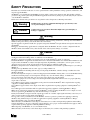


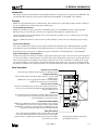
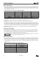

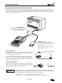

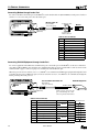
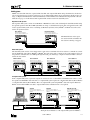


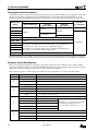
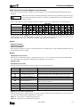
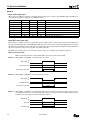
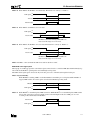


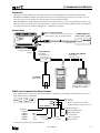
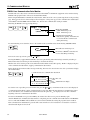
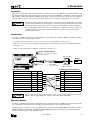
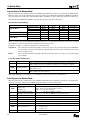
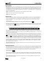


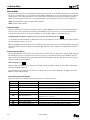
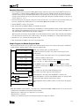

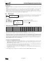
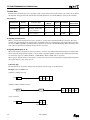
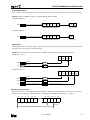
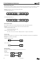

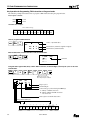
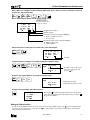


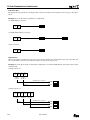
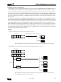
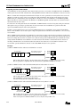
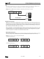
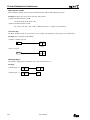

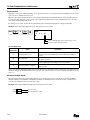
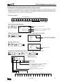
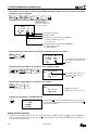


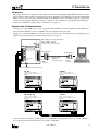
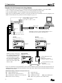

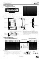
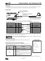

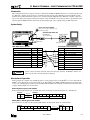


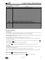


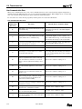
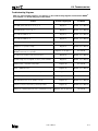
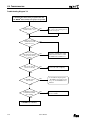
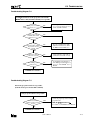
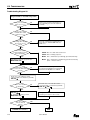

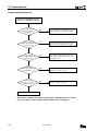
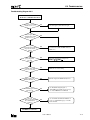
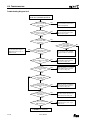

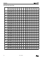
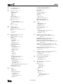
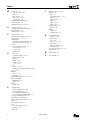

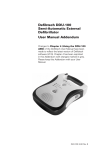


![DGID Software [EN]](http://vs1.manualzilla.com/store/data/005717670_1-65b44a14cec330296683d17d94da3fca-150x150.png)