1
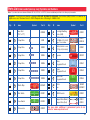
About Your Snap Circuits Parts
(Part designs are subject to change without notice).
Note: If you have the more advanced Models SC-300, SC-500, or SC-750,
there is additional information in your other project manual(s).
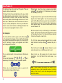
The base grid functions like the printed circuit boards found in most
electronic products. It is a platform for mounting parts and wires (though the
wires are usually “printed” on the board.
The blue snap wires are just wires used to connect other components, they
are used to transport electricity and do not affect circuit performance. They
come in different lengths to allow orderly arrangement of connections on the
base grid.
The red and black jumper wires make flexible connections for times when
using the snap wires would be difficult. They also are used to make
connections off the base grid (like the projects using water).
The batteries (B1) produce an electrical voltage using a chemical reaction.
This “voltage” can be thought of as electrical pressure, pushing electrical
“current” through a circuit. This voltage is much lower and much safer than
that used in your house wiring. Using more batteries increases the “pressure”
and so more electricity flows.
The slide switch (S1) connects (ON) or disconnects (OFF) the wires in a
circuit. When ON it has no effect on circuit performance.
The press switch (S2) connects (pressed) or disconnects (not pressed) the
wires in a circuit, just like the slide switch does.
W resistor (R1), “resist” the flow of electricity and
Resistors, such as the 100W
are used to control or limit the electricity in a circuit. Increasing circuit
resistance reduces the flow of electricity.
The photoresistor (RP) is a light-sensitive resistor, its value changes from
nearly infinite in total darkness to about 1000W when a bright light shines on it.
A light bulb, such as in the 2.5V lamp (L1), contains a special wire that glows
bright when a large electric current passes through it. Voltages above the
bulb’s rating can burn out the wire.
The motor (M1) converts elecricity into mechanical motion. Electricity is
closely related to magnetism, and an electric current flowing in a wire has a
magnetic field similar to that of a very, very tiny magnet. Inside the motor is
three coils of wire with many loops. If a large electric current flows through
the loops, the magnetic effects become concentrated enough to move the
coils. The motor has a magnet inside so, as the electricity moves the coils to
align them with the permanent magnet, the shaft spins.
The speaker (SP) converts electricity into sound. It does this by using the
energy of a changing electrical signal to create mechanical vibrations (using
a coil and magnet similar to that in the motor), these vibrations create
variations in air pressure which travel across the room. You “hear” sound
when your ears feel these air pressure variations.
The whistle chip (WC) contains two thin plates. When an electrical signal is
applied across them they will stretch slightly in an effort to separate (like two
magnets opposing each other), when the signal is removed they come back
together. If the electrical signal applied across them is changing quickly, then
the plates will vibrate. These vibrations create variations in air pressure that
your ears feel just like sound from a speaker.
The LED (D1) is a light emitting diode, and may be thought of as a special
one-way light bulb. In the “forward” direction (indicated by the “arrow” in the
symbol) electricity flows if the voltage exceeds a turn-on threshold (about
1.5V); brightness then increases. A high current will burn out the LED, so the
current must be limited by other components in the circuit. LEDs block
electricity in the “reverse” direction.
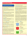
Some types of electronic components can be super-miniaturized, allowing
many thousands of parts to fit into an area smaller that your fingernail. These
“integrated circuits” (ICs) are used in everything from simple electronic toys to
the most advanced computers. The music, alarm, and space war ICs (U1,
U2, and U3) in Snap Circuits are actually modules containing specialized
sound-generation ICs and other supporting components (resistors,
capacitors, and transistors) that are always needed with them. This was done
to simplify the connections you need to make to use them. The descriptions
for these modules are given here for those interested, see the projects for
connection examples:
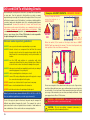
Music IC:
TRG
HLD
(+) - power from batteries
(–) - power return to batteries
OUT - output connection
HLD - hold control input
TRG - trigger control input
(–)
OUT
Music for ~20 sec on power-up, then hold HLD to (+) power
or touch TRG to (+) power to resume music.
(+)
Alarm IC:
IN2
IN1, IN2, IN3 - control inputs
(–) - power return to batteries
OUT - output connection
IN1
IN3
(–)
OUT
(+)
OUT
(+) - power from batteries
(–) - power return to batteries
OUT - output connection
IN1, IN2 - control inputs
IN2
Connect each control input to (–) power to sequence through
8 sounds.
Connect control inputs to (+) power to make five alarm
sounds, see project 22 for configurations.
Space War IC:
IN1
(–)
-4-