1
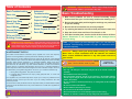
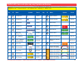
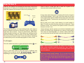
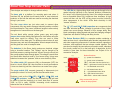
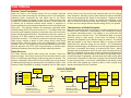
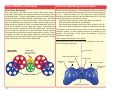
Copyright © 2008 by Elenco® Electronics, Inc. All rights reserved. No part of this book shall be reproduced by
any means; electronic, photocopying, or otherwise without written permission from the publisher.
753305
Table of Contents
Basic Troubleshooting
1
Parts List
How to Use It
2
Advanced
Troubleshooting
9
3
Project Listings
10
Projects #1-63
About Your Snap
Circuits® Parts
4, 5
How It Works
6, 7
General Operating
Instructions
DO’s and DON’Ts of
Building Circuits
!
WARNING: SHOCK HAZARD - Never connect Snap Circuits® to
the electrical outlets in your home in any way!
7
Other Snap Circuits®
Products
11-43
44
2. Be sure that parts with positive/negative markings are positioned
as per the drawing.
3. Be sure that all connections are securely snapped.
4. Try replacing the batteries in the Rover body and remote control unit.
Parts Map
5. Keep the wheels clean and free of lint, thread, or dirt.
46
6. If the disc launcher jams, turn the circuit off and remove all discs.
8
WARNING FOR DISC LAUNCHER (DL) - Moving parts. Keep your face and eyes away
from the front of the disc launcher and from flying discs. Do not place anything into the disc
launcher except the foam discs. Do not reach inside the disc launcher during operation. Do
not launch discs at people, animals, or objects. Eye protection is recommended.
The Federal Communications Commission (FCC) regulates use of the radio frequency
spectrum in the United States to prevent products from interfering with each other.
Deluxe Snap Rover® has been tested and found to comply with the limits for a Class B digital
device, pursuant to part 15 of the FCC Rules. These limits are designed to provide reasonable
protection against harmful interference in a residential installation. Deluxe Snap Rover®
generates, uses and can radiate radio frequency energy and, if not installed and used in
accordance with the instructions, may cause harmful interference to radio communications.
However, there is no guarantee that interference will not occur in a particular installation. If
Deluxe Snap Rover® does cause harmful interference to radio or television reception, which can
be determined by turning Deluxe Snap Rover® off and on, try to correct the interference by:
1. Moving Deluxe Snap Rover® away from the receiver.
2. Contacting Elenco® Electronics for help by calling (800) 533-2441, or e-mail us at
[email protected].
FCC regulations for your Deluxe Snap Rover® require you to accept any interference from
authorized sources and that you shut down if you are causing interference with other
authorized products.
You should never modify the electrical circuit components inside your Deluxe Receiver (RX2)
or Remote Control transmitter as this may cause malfunctions or violate FCC regulations for
this product.
-1-
1. Most circuit problems are due to incorrect assembly, always
double-check that your circuit exactly matches the drawing for it.
Bonus Projects B1 & B2 45
A NOTE ABOUT THE FCC
!
Basic Troubleshooting
Warning to Snap Circuits® Owners: Do not use parts from other Snap Circuits® sets
with this kit. Deluxe Snap Rover® uses higher voltage which could damage those parts.
Page 44 and our website www.snapcircuits.net has approved circuits that you can use.
Elenco® Electronics is not responsible for parts damaged due to
incorrect wiring.
Note: If you suspect you have damaged parts, you can follow the
Advanced Troubleshooting procedure on page 9 to determine which
ones need replacing.
WARNING: Always check your wiring before turning on a circuit.
Never leave a circuit unattended while the batteries are installed.
Never connect additional batteries or any other power sources to
your circuits.
WARNING: CHOKING HAZARD - Small
parts. Not for children under 3 years.
Conforms to
ASTM F963-96A
BATTERIES:
• Use only 1.5V AA type in the Rover body and 9V in the remote control (not
included).
• Insert batteries with correct polarity.
• Non-rechargeable batteries should not be recharged. Rechargable batteries
should only be charged under adult supervision, and should not be recharged
while in the product.
• Do not mix alkaline, standard (carbon-zinc), or rechargeable (nickel-cadmium)
batteries.
• Do not mix old and new batteries.
• Remove batteries when they are used up.
• Do not short circuit the battery terminals.
• Never throw batteries in a fire or attempt to open its outer casing.
• Batteries are harmful if swallowed, so keep away from small children.
Parts List (Colors and styles may vary) Symbols and Numbers
Important: If any parts are missing or damaged, DO NOT RETURN TO RETAILER. Call toll-free (800) 533-2441 or e-mail us at:
[email protected]. Customer Service • 150 Carpenter Ave. • Wheeling, IL 60090 U.S.A.
ID
Name
5
1
11
Part #
Qty.
ID
Name
1-Snap Wire
6SC01
1
R4
10KΩ Resistor
6SCR4
2
2-Snap Wire
6SC02
1
R5
100KΩ Resistor
6SCR5
1
3
3-Snap Wire
6SC03
1
Rover Body
6SCRB
1
4
4-Snap Wire
6SC04
1
RX2
Deluxe Receiver IC
6SCRX2
1
6
6-Snap Wire
6SC06
1
S1
Slide Switch
6SCS1
Base Grid
(11.0” x 7.7”)
6SCBG
1
S2
Press Switch
6SCS2
6SCC7
1
Remote Control Unit
6SCTX1
6SCC4N
1
Antenna for Remote
Control
6SCTX1A
1
Symbol
1
C7
1μF Capacitor
1
C4N
100μF Capacitor
(non-polarized)
1
D4
White LED
6SCD4
1
1
DL
Disc Launcher
6SCDL
1
1
6SCDISC
1
1
15
Foam Discs
1
R1
100Ω Resistor
6SCR1
1
1
1
R2
1KΩ Resistor
6SCR2
1
1
U9
Note: Colors may vary
and are interchangeable.
Qty.
Symbol
Part #
Sound & Recording IC
6SCU9
Jumper Wire (Red)
Jumper Wire (Black)
6SCJ1
6SCJ2
Jumper Wire (Orange)
Jumper Wire (Yellow)
6SCJ3A
6SCJ3B
Jumper Wire (Green)
Jumper Wire (Purple)
6SCJ3C
6SCJ3D
Jumper Wire (Gray)
Jumper Wire (White)
6SCJ3E
6SCJ3F
You may order additional / replacement parts at our website: www.snapcircuits.net
-2-
How To Use It
Install six “AA” batteries (not included) into the bottom of the Rover
body and one 9V battery (not included) into the remote control unit.
Install the antenna into the remote control unit by screwing it in.
Antenna
Remote
control
Front of Rover
–
There is also a 1-snap wire that is used as a spacer or for
interconnection between different layers.
A large clear plastic base grid is included with this kit to keep the
circuit blocks together, it fits on top of the Rover body. You will see
evenly spaced posts that the different blocks snap onto, these keep
your circuit together. The base has rows labeled A-G and columns
labeled 1-10.
Next to each part in every circuit drawing is a small number in
black. This tells you which level the component is placed at. Place
all parts on level 1 first, then all of the parts on level 2, then all of
the parts on level 3, etc.
The Deluxe Snap Rover® Kit uses building blocks with snaps to
build the different electrical and electronic circuits in the projects.
Each block has a function: there are switch blocks, LED blocks,
different length wire blocks, etc. These blocks are in different colors
and have numbers on them so that you can easily identify them.
The circuit you will build is shown in color and numbers, identifying
the blocks that you will use and snap together to form a circuit.
Jumper wires are used to connect your circuits to the batteries and
motors in the Rover body. Snap them on as shown in the projects.
The colors are interchangeable, so it doesn’t matter which color
you use (however the red and black wires are longer than the rest).
For Example:
This is the switch block which is green and has the marking S1 on it.
This is a wire block which is blue and comes in different wire
lengths. This one has the number 2 , 3 , 4 , 5 , 6 , or 7 on it
depending on the length of the wire connection required.
-3-
Note: While building the projects, be careful not to accidentally
make a direct electrical connection across the + and – snaps for
the batteries (a “short circuit”), as this may damage and/or quickly
drain the batteries.
Warning to Snap Circuits® owners: Do not use parts from other
Snap Circuits® sets with this kit unless directed to do so. The Snap
Rover® uses higher voltage which could damage those parts. Page
44 and our website www.snapcircuits.net has approved circuits
that you can use.
About Your Snap Circuits® Parts
!
Warning to Snap Circuits® owners: Do not use parts from other Snap Circuits® sets with this kit. The Snap Rover® uses higher
voltage which could damage those parts. Page 44 and our website www.snapcircuits.net has approved circuits that you can use.
(Part designs are subject to change without notice).
The base grid is a platform for mounting parts and wires. It
functions like the printed circuit boards found in most electronic
products, or like how the walls are used for mounting the electrical
wiring in your home.
The blue snap wires are just wires used to connect other
components, they are used to transport electricity and do not affect
circuit performance. They come in different lengths to allow orderly
arrangement of connections on the base grid.
The red, black, white, orange, yellow, green, gray, and purple
jumper wires make flexible connections for times when using the
snap wires would be difficult. They also are used to make
connections off the base grid. The different colored wires all work
the same way, and are interchangeable. Wires transport electricity
just like pipes are used to transport water.
The batteries (in the Rover body) produce an electrical voltage
using a chemical reaction. This “voltage” can be thought of as
electrical pressure, pushing electrical “current” through a circuit just
like a pump pushes water through pipes. This voltage is much lower
and much safer than that used in your house wiring. Using more
batteries increases the “pressure” and so more electricity flows.
The LED (D4) is a light emitting diode, and may be thought of as a
special one-way light bulb. In the “forward” direction (indicated by
the “arrow” in the symbol) electricity flows if the voltage exceeds a
turn-on threshold (about 3V); brightness then increases. A high
current will burn out the LED, so the current must be limited by
other components in the circuit. LEDs block electricity in the
“reverse” direction.
The 1μF (C7) and 100μF (C4N) capacitors are components that
can store electrical pressure (voltage) for periods of time, higher
values have more storage. Because of this storage ability they
block unchanging voltage signals and pass fast changing voltages.
Capacitors are used for filtering and delay circuits.
The Deluxe Receiver (RX2) is a complex module containing a
radio receiver circuit, a specialized radio decoder integrated circuit,
and other supporting components. It includes resistors, capacitors,
inductors, and transistors that are always needed together. This
was done to simplify the connections you need to make, otherwise
this circuitry would not fit on the base grid. A description for this
module is given here for those interested, see Project #1 for a
connection example:
(+)
LBUT
L–
The slide switch (S1) connects (ON) or disconnects (OFF) the
wires in a circuit. When ON it has no effect on circuit performance.
It turns on electricity just like a faucet turns on water from a pipe.
RBUT
L+
(+)
R–
The press switch (S2) connects (pressed) or disconnects (not
pressed) the wires in a circuit, just like the slide switch does.
(+)
Resistors, such as the 100Ω (R1), 1KΩ (R2), 10KΩ (R4), and
100KΩ (R5) resistors, “resist” the flow of electricity and are used
to control or limit the electricity in a circuit. Note that “K” means
1000, so R4 is really 10,000Ω. Increasing circuit resistance
reduces the flow of electricity.
R+
(–)
!
Deluxe Receiver:
(+) - power from batteries
(–) - power return to batteries
LBUT - left button function (active low)
RBUT - right button function (active low)
L – - left backward motor drive
L+ - left forward motor drive
R – - right backward motor drive
R+ - right forward motor drive
ABC switch - selects radio channel
Only connect this part as
shown in the projects!
-4-
About Your Snap Circuits® Parts (continued)
The Sound & Recording IC (U9) module contains an integrated
recording circuit, a dual timer integrated circuit for making audio
tones, microphone, speaker, filtering circuitry, and other supporting
components. It includes resistors (adjustable and fixed), capacitors,
transistors and diodes that are needed to make the recordings and
play all the sounds. Recording time is up to 12 seconds. A
description for this module is given here for those interested, see
Project #1 for a connection example and for instructions on how to
use it:
(+)
REC
2TC
TRG
2TT
SP
2TO
Sound & Recording IC:
(+) - power from batteries
CONT
(–)
REC - recording control
TRG - main tone activation/disable
PLAY - play recording
2TC - modulating tone control
2TT - modulating tone activation/disable
!
Only connect this
part as shown in
the projects!
!
L–
N1
(+)
Rover Rear:
(+) - power from batteries
(–) - power return to batteries
ROVER REAR
L+ - left forward motor drive
L – - left backward motor drive
R+ - right forward motor drive
R+
L+
N2
(–)
R – - right backward motor drive
Only connect this part as N1, N2 - not used
shown in the projects!
(–) - power return to batteries
SP - external speaker control
PLAY
R–
2TO - modulating tone output
CONT - main tone control
The Disc Launcher (DL) contains two motors. One motor starts
first and spins a cylinder at high speed. Another motor starts a few
seconds later and slowly moves a disc into launch position using
gears and a hook. When the disc enters launch position the
cylinder grabs it and propels it out of the launcher. The motors are
controlled by an integrated circuit along with resistors, capacitors,
and transistors. The same circuit also controls the lights in the
“eyes”. A description for this module is given here for those
interested, see Project #1 for a connection example:
Knobs: upper controls modulating tone
lower controls main tone
frequency
EXT
Disc Launcher:
Red light: this is a recording indicator
CONT
The motors (in the Rover body) convert elecricity into mechanical
motion. Electricity is closely related to magnetism, and an electric
current flowing in a wire has a magnetic field similar to that of a
very, very tiny magnet. Inside the motor is a coil of wire with many
loops wrapped around metal plates. If a large electric current flows
through the loops, it will turn ordinary metal into a magnet. The
motor shell also has a magnet on it. When electricity flows through
the coil, it magnetizes the metal plates and they repel from the
magnet on the motor shell - spinning the shaft. A small gear is on
the end of the shaft and spins with it.
-5-
(+) - power from
batteries
(–) - power return to
batteries
(+)
(–)
!
CONT - control
input (active low)
EXT - external
device control
(active low)
Only connect this part as
shown in the projects!
How It Works
Remote Control Transmitter:
When the levers in the Remote Control Unit are pushed, electrical
contacts are made connecting the 9V battery power to the transmitter,
indicating which commands the user wants sent to the Rover.
Forwards/Backwards commands for each set of wheels and two extra
functions are controlled by different levers or buttons. Each of these use
a different set of electrical contacts which encode a sequence of
electrical pulses; the pulse sequence depends on which command(s) are
being sent. The spacing between the sequences represents which
channel setting (A-B-C) the remote control is on. This allows three units
to use the same operating frequency in the same room at the same time
without interfering with each other. An electrical circuit that is tuned to a
frequency of 27 MHz creates a signal that is sent to the antenna when
the pulses are active. The antenna converts this electrical energy into
radio energy, creating a stream of radio energy bursts, which travel
through the air and are picked up by, and understood by, the radio
receiver in the car. The frequency of 27 MHz was selected for your Rover
with the approval of the FCC (the US government) to minimize radio
interference between this product and all other electrical products.
Radio Receiver:
The Rover antenna collects radio energy and converts it back into
electrical energy. If the Rover is turned on, then the radio receiver in the
Rover is continuously monitoring the radio energy from its antenna. The
receiver is basically a filter which is tuned to amplify any energy around
27 MHz and block energy the antenna picks up outside this region. If the
Remote Control Transmitter is sending commands, then its radio signal
LBUT
RBUT
L-F
L-B
R-F
R-B
Pulse Sequence,
depends on which
command(s) are being
sent and channel used
Characteristics of Radio Reception:
Many factors affect the ability of the Rover to receive commands from its
Remote Control Transmitter. A weak battery in the Transmitter will result
in a weaker transmitted signal; if the battery is very weak then the
Transmitter may not function at all. The Transmitter’s ability to convert
electrical energy to radio energy is best when its antenna is fully
extended and degrades as the antenna length is reduced. The same
thing also applies to the Rover antenna’s ability to convert the radio
signal back into electrical energy for the receiver. The Transmitter’s
antenna transmits energy in all directions so as the range between it and
the Rover is increased, less energy is received at the Rover. When
operated with strong batteries and in an open area, the range will be at
least 25 ft. Obstacles such as walls, furniture, and trees will degrade the
radio signal’s ability to travel through air and reduce the operating range,
but will never block it completely. In some cases more radio energy may
travel from the Transmitter to the Rover by going around obstacles than
by going through them. In the Rover, weak batteries will reduce power
to the motor and degrade the receiver’s ability to filter, amplify, and
decode commands from the Transmitter.
BLOCK DIAGRAM
27 MHz
Signal
Encoding
Circuitry
will be picked up by the receiver and converted back into the original
pulse sequence. Decoding circuitry then determines which commands
were sent by examining the pulses in the sequence. Signals are then
sent to motors that drive the wheels to execute the commands, or the
other R/C Receiver outputs to control other functions. Commands sent
to other receivers using a different channel setting (A-B-C) are ignored.
HOW IT WORKS
Filter/
Amplifier
Sequence
of Radio
Frequency
Pulses
Filter/
Amplifier
Left
Motor
128-1
Gear Ratio
Left
Wheels
Right
Motor
128-1
Gear Ratio
Right
Wheels
Decoding
Circuitry
Pulse Sequence,
depends on which
command(s) were sent
and channel used
Control For Two
Other Functions
-6-
How It Works (continued)
General Operating Instructions
Rover Drive Mechanism:
Build the circuit for Project #1. Set the channel switches on the remote
control unit and Deluxe Receiver module (RX2) to the same setting (A,
B, or C). Place the Rover on a flat, open area, turn the ON/OFF
switch on the remote control unit and the slide switch (S1) to ON, and
extend the antenna on the Remote Control.
The small gear on the Motor drives a larger gear, which drives a
larger gear, which drives two larger gears (one on each side), which
drive larger gears. The last, largest gears are fixed on shafts that are
attached to the front and back wheels, making them move. Note that
interlocking gears spin in opposite directions. Also notice that in the
sets of interlocking gears between the Motor and the gears on the
wheel shafts, the number of “teeth” is increased each time (40-8, 448, 64-44, and 64-20), for 128:1 gear ratio overall. This means the
Motor must rotate 128 times to rotate the wheels once. The reason
for this is that if the Motor were to drive the wheels directly then the
Rover would be so fast that it would be impossible to control. Using
the gears to reduce the speed also makes the wheels move with
much greater force, preventing the Rover from getting stuck in rough
terrain and allowing it to carry heavy loads uphill.
Push both levers forward to make Snap Rover® go forward.
Push both levers backward to go backward.
Push the left lever backward and the right lever forward to turn left.
Push the left lever forward and the right lever backward to turn right.
The buttons on the remote control unit are used to control the disc
launcher, sounds, or other special functions as described in the
projects. The functions of the sound & recording IC (U9) are
described in Project #1.
Never operate Snap Rover® in the street.
Never drive your Rover in rain, snow, mud, sand, dirt, or on a wet
floor, as damage may result.
GEARS
Antenna
Motor gear
Spins 128 times
faster than wheels
Power ON indicator LED
Power switch
Left control
lever
Left function
button
Right function button
Right control
lever
Wheel shaft
Channel selector switch
-7-
DO’s and DON’Ts of Building Circuits
After building the circuits given in this booklet, you may wish to experiment
on your own. Use the projects in this booklet as a guide, as many
important design concepts are introduced throughout them. Every circuit
will include a power source (the batteries), a resistance (which might be
a resistor, motor, integrated circuit, etc.), and wiring paths between them
and back. You must be careful not to create “short circuits” (very lowresistance paths across the batteries, see examples below) as this will
damage components and/or quickly drain your batteries. Only connect the
ICs using configurations given in the projects, incorrectly doing so may
damage them. Elenco® Electronics is not responsible for parts
damaged due to incorrect wiring.
Here are some important guidelines:
Examples of SHORT CIRCUITS - NEVER DO THESE!!!
(+)
!
NEVER
DO!
Placing a jumper
wire directly across
the battery snaps is
a SHORT CIRCUIT.
(–)
When the switch (S1) is turned on, this large circuit has a SHORT
CIRCUIT path (as shown by the arrows). The short circuit prevents any
other portions of the circuit from ever working.
ALWAYS use eye protection when experimenting on your own.
!
ALWAYS include at least one component that will limit the current
through a circuit, such as a resistor, motor, or the disc launcher,
RX2, and U9 modules (which must be connected properly).
ALWAYS use the LED and switches in conjunction with other
components that will limit the current through them. Failure to
do so will create a short circuit and/or damage those parts.
NEVER
DO!
!
ALWAYS disconnect your batteries immediately and check your wiring if
something appears to be getting hot.
ALWAYS check your wiring before turning on a circuit.
ALWAYS connect the disc launcher, RX2, and U9 modules using
configurations given in the projects or as per the connection
descriptions for the parts.
NEVER connect to an electrical outlet in your home in any way.
NEVER leave a circuit unattended when it is turned on.
For all of the projects given in this book, the parts may be arranged in
different ways without changing the circuit. For example, the order of parts
connected in series or in parallel does not matter — what matters is how
combinations of these sub-circuits are arranged together.
WARNING: SHOCK HAZARD - Never connect Snap Circuits® to
the electrical outlets in your home in any way!
NEVER
DO!
!
NEVER
DO!
ROVER REAR
(+)
(–)
!
NEVER DO!
You are encouraged to tell us about new circuits you create. If they are
unique, we will post them with your name and state on our website at
www.snapcircuits.net/kidkreations.htm. Send your suggestions to
Elenco® Electronics.
Elenco® provides a circuit designer so that you can make your own Snap
Circuits® drawings. This Microsoft® Word document can be downloaded
from www.snapcircuits.net/SnapDesigner.doc or through the
www.snapcircuits.net website.
!
Warning to Snap Circuits® owners: Do not use parts from
other Snap Circuits® sets with this kit except for the circuits on
page 44. The Snap Rover® uses higher voltage which could
damage those parts. Our website www.snapcircuits.net also
has approved circuits that you can use.
-8-
Advanced Troubleshooting
(Adult supervision recommended)
Elenco® Electronics is not responsible for parts damaged due to
incorrect wiring.
If you suspect you have damaged parts, you can follow
this procedure to systematically determine which ones
need replacing:
6. Sound & Recording IC (U9) and the 1μF and 100μF capapacitors (C7,
C4N): Build Project #62 (Lunar Messenger); the parts should work as
described in it.
7. Remote control unit and Deluxe Receiver (RX2): Build Project #36 (Remote
Control Right Lite) and test that the wheels and white LED (D4) can be
controlled by the remote control unit as described. Be sure you have built the
circuit correctly and have good batteries in both the Rover body and remote
control. Have the A-B-C switches on the remote control and deluxe receiver set
to the same channel, have turned on the remote control turned on and its
antenna extended, and make sure it is not being interfered with by other remote
control transmitters.
ROVER REAR
Now move the jumper wires to test the other two
wheels, if they don’t move then the Rover body is
damaged. Remove the gray wire; four LEDs on the side
should light.
ROVER REAR
1. Rover body and jumper wires: Flip the Rover body
upside down and make sure the wheel mechanisms
are clean. Install batteries in the Rover body and
connect jumper wires to the Rover rear as shown; two
wheels should move. Replace the orange and gray
jumper wires with each of the other colors to see if any
of the jumpers are damaged. If the wheels don’t move
for any combination of wires, then the Rover body is
damaged. Remove the gray wire; four LEDs on the side
should light.
5. Disc Launcher (DL) module: Build Project #42 (Disc Launcher). The launcher
should start up and launch discs as described. If the launcher is jammed,
turning off the circuit and removing all discs can usually fix it.
2. Slide switches (S1) and press switch (S2): Build Project #51 (Helpless
Rover) and test each slide switch by making it turn the wheels on/off. Replace
the slide switch with the press switch; it works the same way.
3. Snap wires: Build Project #6 but replace the switch with each of the snap
wires (including the 1-snaps), test them one at a time.
4. White LED (D4) and 100Ω, 1KΩ, 10KΩ, and 100KΩ resistors (R1, R2, R4,
R5): Build this mini-circuit and turn on the switch, the LED should be bright or
it is damaged. Replace the 3-snap with each of the resistors (one at a time),
the LED should be bright with R1, slightly dimmer with R2, much dimmer with
R4, and very dim with R5; if not then the resistor is defective.
Elenco® Electronics, Inc.
ROVER REAR
150 Carpenter Avenue • Wheeling, IL 60090 U.S.A.
Phone: (847) 541-3800 • Fax: (847) 520-0085
e-mail: [email protected] • Web site: www.elenco.com
You may order additional / replacement parts at:
www.snapcircuits.net
-9-
Project Listings
Project #
1
2
3
4
5
6
7
8
9
10
11
12
13
14
15
16
17
18
19
20
21
22
23
24
25
26
27
28
29
30
31
32
Description
Space Rover
Sound Disable Rover
Fun Sounds Rover
Spooky Sounds Rover
Simple Sounds
Not So Simple Sounds
Space Sounds
Audio Recorder
One Sound
Lighthouse Rover
Remote Sound
Remote Sound Switcher
Parallel Pitch Reducer
Series Pitch Reducer
Resistor Row
Ways to Light a Light
Nightlite Rover
Remote Drive Rover
Tone Flicker
Clicker Flicker
Volume Control
Electronic Metronome
Flickering Metronome
Not So Often Timer
Stop & Light
Quad Red Blinker
Quick-Slow Blinker
Super Blinker
Goofy Blinker
Noisy Flasher
Simple Flasher
Car Alarm
Page #
11
12
13
14
15
15
16
16
17
17
18
18
19
19
20
20
21
21
22
22
22
23
23
24
24
25
25
26
26
26
26
27
Project #
33
34
35
36
37
38
39
40
41
42
43
44
45
46
47
48
49
50
51
52
53
54
55
56
57
58
59
60
61
62
63
Description
Switched Tone Blinker
Recording Blinker
Tri-Switch Blinker
Remote Control Flasher
Disc Launcher
Remote Control Right Lite
Remote Control Left Lite
Current Diverter
Two Tone Flash
Multi-Tone Rover
Remote Sound & Light
Double Launcher
Remote Control Launcher
Groovy Launcher
Martian Monster
Venus Visitor
Easy Rover
2-to-1 Tone
Jupiter Jumble
Helpless Rover
Generator
Lost Explorer
Write Your Parts
The Sound of Water
Salt Pitch Changer
Frequency Resistors
Big Bully
Little Bully
Electricity Station
Audio-Visual Morse Code
Lunar Messenger
Page #
27
28
28
29
29
30
30
31
31
32
32
33
33
34
34
35
36
36
37
37
38
38
39
39
39
40
41
41
42
42
43
-10-
Project #1
Space Rover
OBJECTIVE: To build a remote control vehicle.
!
Turn knobs
to adjust sound.
ROVER REAR
+
WARNING: Moving parts. Keep face and eyes away from
the front of the disc launcher and from flying discs.
Microphone
Cha nnel sw
i
ol unit.
nt r
co
n remot
ho
e
tc
Be sure to route the jumper wires
under U9 as shown.
Snap Circuits®: The Snap Circuits® Kit
uses electronic blocks that snap onto a
clear plastic base grid to build different
circuits. These blocks have different colors
and numbers on them so that you can
easily identify them.
Preparation: Install six (6) “AA” batteries into
the bottom of the Rover body and one 9V
battery into the remote control unit (batteries
not included). Install the antenna into the
remote control unit by screwing it in. Place the
base grid on the Rover body; you may lock it
into position by turning the hexagonal
alignment posts (shown here), if desired.
Assembly: Build the circuit shown by placing all the parts with a black 1
next to them on the clear plastic base grid first. Then, assemble parts
marked with a 2, and finally the parts marked with a 3. Be sure to place the
D4 (black), RX2 (red), and U9 (orange) parts with their (+) side oriented as
shown. Connect the black colored jumper wire as shown and connect the
-11-
other colored jumper wires to the rear of the body as shown (the colors are
interchangeable). Set the channel switches on the remote control unit and
Deluxe Receiver module (RX2) to the same setting (A, B, or C).
Recording & Sounds: Turn on the slide switch (S1). The recorded
message (if any) will play, followed by space sounds. Turn either of the
knobs on the sound & recording IC (U9) to adjust the tone and beat of the
sounds. Push and hold the press switch (S2) and speak into the
microphone on U9 to record a message of up to 12 seconds. The red light
on U9 will be on while you are recording.
Remote Control: Turn on the remote control unit, extend the antenna, and
use the levers to drive the Rover around. Press the left button on the remote
control to play the recorded message (if any).
Launching Discs: Place some of the foam discs into the disc launcher
(DL). Press the right button on the remote control to prepare the launcher;
the eyes flash. The launcher takes a few seconds to get ready, then press
the right button again to fire or hold it down to fire continuously. The
launcher shuts off after a few seconds. If the launcher jams, just remove the
discs to fix it. The white LED (D4) lights up when the launcher is active, so
you can launch discs in the dark.
Project #2
Sound Disable Rover
OBJECTIVE:
annoying.
To turn off the space sounds when they get
Added part to circuit.
Modify the Project #1 circuit by adding
a second slide switch (S1) over the
U9 sound and recording IC, using two
1-snaps as shown. The circuit works
the same as before except turning on
the new S1 switch shuts off the space
sounds.
Now your Rover can sneak up on
someone, play your recording, and
launch the discs!
ROVER REAR
As an option, change the sound into
just a simple tone by removing the 2snap wire on the upper-right of U9 (on
level 3).
Cha nnel sw
i
ol unit.
nt r
co
n remot
ho
e
tc
!
WARNING: Moving parts. Keep face and eyes away from
the front of the disc launcher and from flying discs.
-12-
Project #3
Fun Sounds Rover
ROVER REAR
OBJECTIVE: To make cute sounds.
Cha nnel sw
i
Parts in the circuit:
ol unit.
nt r
co
n remot
ho
e
tc
Parts you can
replace them with:
!
-13-
WARNING: Moving parts. Keep face and eyes away from
the front of the disc launcher and from flying discs.
Modify the Project #2 circuit by adding a the 100μF capacitor (C4N) over
the 10K resistor (R4), using a 1-snap as shown. The circuit works the
same as before except that the space sounds sound a little different. Turn
knobs on U9 to change the sound.
Next replace the 10K resistor (R4) with either the 1K resistor (R2) or the
100K resistor (R5), and turn the knobs on U9 to see how the range of
sounds has been changed.
Now replace the 100μF capacitor (C4N) with the 1μF capacitor (C7), and
turn the knobs on U9 to see how the range of sounds has been changed.
Try different combinations of resistor and capacitor values.
Changing the resistor and capacitor values adjusts an electronic delay,
which changes the sound effects in an electrical signal controlling a
speaker (SP).
Project #4
Spooky Sounds Rover
ROVER REAR
OBJECTIVE: To turn change the space sounds.
Cha nnel sw
i
Added part to circuit.
ol unit.
nt r
co
n remot
ho
e
tc
Part in the circuit:
Parts you can
replace it with:
Modify the Project #2 circuit by adding a the 100μF capacitor (C4N) over
the 10K resistor (R4), using a 1-snap as shown. The circuit works the
same as before except that the space sounds sound a little different. Turn
knobs on U9 to change the sound.
Next replace the 10K resistor (R4) with either the 1K resistor (R2) or the
100K resistor (R5), and turn the knobs on U9 to see how the range of
sounds has been changed.
Now replace the 100μF capacitor (C4N) with the 1μF capacitor (C7), and
turn the knobs on U9 to see how the range of sounds has been changed.
Try different combinations of resistor and capacitor values.
!
WARNING: Moving parts. Keep face and eyes away from
the front of the disc launcher and from flying discs.
Changing the resistor and capacitor values adjusts an electronic delay,
which changes the sound effects in an electrical signal controlling a
speaker (SP).
-14-
Project #5
Simple Sounds
Turn knob
to adjust pitch.
Project #6
ROVER REAR
OBJECTIVE: To make sounds electronically.
Build the circuit with the base grid
centered on the Rover body, and
connect the jumper wires as shown.
Turn on the slide switch (S1). The
recorded message may play, followed
by a tone. Turn the lower knob on the
sound & recording IC (U9) to adjust
the pitch (frequency) of the tone.
Not So Simple Sounds
Turn knobs
to adjust sound.
-15-
ROVER REAR
OBJECTIVE: To make sounds electronically.
Build the circuit with the base grid
centered on the Rover body, and
connect the jumper wires as shown.
Turn on the slide switch (S1). The
recorded message may play, followed
by a tone. Turn the knobs on the
sound & recording IC (U9) to adjust
the sound.
Project #7
Space Sounds
ROVER REAR
OBJECTIVE: To make exciting sounds.
Project #8
Build the circuit with the base grid
centered on the Rover body, and
connect the jumper wires as shown.
Turn on the right slide switch (S1).
Turn the knobs on the sound &
recording IC (U9) to make a variety of
space sounds.
Audio Recorder
OBJECTIVE: To make an electronic recording and play it back.
Keep OFF. Slide
to ON to record
message, then
slide back to OFF.
ROVER REAR
Build the circuit with the base grid centered
on the Rover body, and connect the jumper
wires as shown. Turn off the left slide switch
(S1) and turn on the right slide switch.
Microphone
Push to play
recording
On/Off
Turn on the left slide switch and talk into the
microphone to make a recording; turn off
the left switch when finished. The red light
on U9 will be on while you record, it goes
out when you finish or when the memory is
full. Your recording can be up to 12 seconds
long.
Push the press switch (S2) to play your
recording.
-16-
Project #9
One Sound
OBJECTIVE: To make sound for a while.
Build the circuit with the base grid centered
on the Rover body, and connect the jumper
wires as shown. TURN THE KNOBS on U9
TO THE LEFT setting. Turn on the slide
switch (S1), the recorded message (if any)
may play.
ROVER REAR
Turn knobs
to the LEFT
setting.
+
Push the press switch; a tone is heard for a
few seconds and then shuts off. You can
adjust how long the tone plays for by turning
the upper U9 knob a little to the right. You
can adjust the pitch of the tone by turning
the lower knob on U9 a little to the right.
If the upper U9 knob is set too far to the
right then the sound will seem to stay on
forever. If the lower U9 knob is set too far to
the right then you may not hear any sound.
Project #10
Lighthouse Rover
+
-17-
ROVER REAR
OBJECTIVE: To make a rotating light.
Build the circuit, place the base grid
centered on the Rover body, and
connect the jumper wires as shown.
Place the Snap Rover® in the middle of
a dimly lit room and turn on the slide
switch (S1). The light will shine around
the room as Snap Rover® spins.
Project #11
Remote Sound
OBJECTIVE: To make sound for a while.
ROVER REAR
+
Build the circuit with the base grid centered on the
Rover body, and connect the jumper wires as shown.
TURN THE KNOBS on U9 TO THE RIGHT setting. Turn
on the slide switch (S1).
Turn on the remote control unit and extend the antenna.
Push the right button on the remote control; a tone is
heard for a few seconds and then shuts off. You can
adjust how long the tone plays for by turning the upper
U9 knob a little to the left. You can adjust the pitch of the
tone by turning the lower knob on U9 a little to the left.
Turn knobs
to the LEFT
setting.
Project #12
ntrol unit.
co
annel sw
it
Ch
on remote
ch
You can use the right remote control lever to move
Rover in a circle, but the left wheels will not work.
If the upper U9 knob is set too far to the left then the
sound will seem to stay on forever. If the lower U9 knob
is set too far to the left then you may not hear any
sound.
Remote Sound Switcher
OBJECTIVE: To change sounds by remote control.
Build the circuit with the base grid centered
on the Rover body, and connect the jumper
wires as shown. Turn on the remote control
unit and extend the antenna. Turn on the
slide switch (S1), you will hear a tone (a
recording may play first). Turn the lower
knob on U9 to the right for the best effects.
ROVER REAR
Turn knobs
to the LEFT
setting.
Push the left button on the remote control to
change the sound. If the lower knob on U9
is set to the right then the pitch of the tone
will change, otherwise the tone shut off.
annel sw
it
Ch
ntrol unit.
co
on remote
ch
Replace the 10K resistor (R4) with any of
the other resistors (R1, R2, or R5) or
replace the 1μF capacitor (C7) with the
100μF capacitor (C4N) and see how the
sound changes.
-18-
Project #13
Parallel Pitch Reducer
ROVER REAR
OBJECTIVE: To show how resistors work.
Project #14
Turning on the switch
places the 100 ohm
resistor (R1) in parallel
with the 10K ohm
resistor (R4), changing
the resistance which
controls the pitch of
the tone.
Build the circuit with the base grid centered on the Rover body,
and connect the jumper wires as shown. Set the upper knob
on the U9 to the middle and the lower knob to the right. Turn
on the top slide switch (S1) to hear a tone (sometimes a
recording will play first).
Turn on the lower slide switch (S1) to hear a lower-pitch tone
or turn it off for a higher-pitch tone. Push the press switch (S2)
to make the sound multi-tone.
The upper U9 knob changes the multi-tone effects and the
lower U9 knob changes the tone pitch.
Option A: replace either resistor (R1 or R4) with the 1K ohm
resistor (R2).
Series Pitch Reducer
ROVER REAR
OBJECTIVE: To show how resistors work.
-19-
Turning off the switch
places the 10K ohm
resistor (R4) in series
with the 100 ohm
resistor (R1), changing
the resistance which
controls the pitch of
the tone.
Modify the preceding circuit to match this
one. It works the same way even though
the resistors are arranged differently.
Option A: replace either resistor (R1 or R4)
with the 1K resistor (R2).
Project #15
Resistor Row
ROVER REAR
OBJECTIVE: To learn about resistors.
+
Project #16
When the slide switches are
off the larger resistors (R2
and R4) are connected in a
series, limiting the flow of
electricity to the white LED.
Turning on the slide switches
bypasses the larger resistors
and the LED gets brighter.
Connecting resistors in a
series
increases
the
resistance.
Build the circuit and
connect the jumper
wires as shown. Push
the press switch (S2) to
turn on the white LED
(D4), and use the slide
switches (S1) to vary
the brightness.
If you replace one of
the resistors with the
much larger 100K
resistor (R5), the white
LED may not light at all.
Ways to Light a Light
+
ROVER REAR
OBJECTIVE: To learn about resistors.
When the slide switches are on
the smaller resistors (R1 and
R2) are connected in parallel
with the larger one (R4),
increasing the flow of electricity
to the white LED. Turning on the
slide switches provides alternate
paths around the largest resistor
and the LED gets brighter.
Connecting resistors in parallel
decreases the resistance.
Build the circuit and
connect the jumper
wires as shown. Push
the press switch (S2) to
turn on the white LED
(D4), and use the slide
switches (S1) to vary
the brightness.
If you replace one of
the resistors with the
much larger 100K
resistor (R5), it will be
almost the same as
leaving that one out of
the circuit.
-20-
Project #17
Nightlite Rover
+
ROVER REAR
OBJECTIVE: To drive around in the dark.
B
Build the circuit (being sure to connect all
eight colored jumper wires), and turn on
the right slide switch (S1). Use the levers
on the remote control unit to drive Rover
around. The white LED (D4) in front acts
as a headlight, so you can use it in a dark
room.
If the left slide switch is off then you will
hear a tone. Turn the knobs on the sound
& recording IC (U9) to change the tone.
Press the left button on the remote control
to play the recorded message. Push the
press switch (S2) and talk into the
microphone on U9 (sound & recording IC)
to change the recording.
Cha nnel sw
i
A
ol unit.
nt r
co
n remot
ho
e
tc
Project #18
Remote Drive Rover
OBJECTIVE: To build a remote control vehicle.
Move the end of the red jumper wire that is at the location marked A to
the location marked B (on RX2). Now the white LED is controlled by
the right button on the remote control unit.
-21-
Project #19
Tone Flicker
B
+
Build the circuit and connect the jumper wires as
shown, note that the 1KΩ resistor (R2) is underneath
the 100μF capacitor (C4N). Turn on the right slide
switch (S1), you hear a tone and the white LED (D4)
flashes. Turn on the left slide switch to shut off the tone
and push the press switch (S2) to stop the flashing.
Project #20
Clicker Flicker
OBJECTIVE: To hear sounds and flash lights.
Add the purple jumper wire across the points marked
A & B over the sound & recording IC (U9). The circuit
works the same way except you hear a clicking sound
instead of a musical tone.
Project #21
Volume Control
OBJECTIVE: To control the volume of sound.
ROVER REAR
A
ROVER REAR
OBJECTIVE: To hear sounds and flash lights.
Build the circuit and connect the jumper wires as
shown. You hear a tone, use the switches (S1 and
S2) to adjust the volume.
Turning on the switches diverts some electrical
energy away from the speaker, reducing the volume
of the sound.
Use the knobs on the sound & recording IC (U9) if
you want to change the tone.
-22-
Project #22
Electronic Metronome
OBJECTIVE: To learn about metronomes.
ROVER REAR
Build the circuit and connect the jumper wires as
shown. Turn on one of the slide switches (S1) and
adjust lower knob on the sound & recording IC (U9).
The left switch adds the 100μF capacitor (C4N) to
the circuit, which regulates the sound to be a slow
clicking. The left switch adds the smaller 1μF
capacitor (C7) to the circuit, giving a much faster
clicking. If the U9 knob is set so the clicking is fast,
the sound appears to be a continuous tone.
When the circuit is clicking about once a second
then it feels like the “beat” of a song. It is like a
metronome, which is used to keep time for the
rhythm of a song.
Project #23
Flickering Metronome
ROVER REAR
OBJECTIVE: To learn about metronomes.
+
-23-
This is a metronome like the preceding circuit; it
makes a clicking sound. Use the lower knob on the
sound & recording IC (U9) and the left slide switch
(S1) to adjust the click rate. The white LED (D4) is
also flickering at the same rate; you may need to
look closely at it to see the light.
Project #24
Not So Often Timer
ROVER REAR
OBJECTIVE: To make cute sounds.
Project #25
Build the circuit and turn on the right slide swtich
(S1). Use the knobs on the sound & recording IC
(U9) to adjust the tone.
Push and hold the press switch (S2) to change the
sound from a tone to clicking. Turn on the left slide
switch to lower the clicking rate, by adding the
100μF capacitor (C4N) to the circuit.
Stop & Light
+
ROVER REAR
OBJECTIVE: To make cute sounds.
Build the circuit and turn on the slide swtich (S1).
Use the knobs on the sound & recording IC (U9) to
adjust the tone.
Push and the press switch (S2) to stop the sound
and light the white LED (D4).
You can change the sound by adding the 100μF
capacitor (C4N) directly over the 100KΩ resistor
(R5) using two 1-snaps.
-24-
Project #26
Quad Red Blinker
ROVER REAR
OBJECTIVE: To make cute sounds and flash lights.
Project #27
Build the circuit and turn on the right slide swtich
(S1). The red lights in the Rover body are blinking
and a tone is heard. Use the knobs on the sound &
recording IC (U9) to adjust the blink rate and tone.
Turn on the left slide switch to shut off the sound.
Quick-Slow Blinker
ROVER REAR
OBJECTIVE: To make cute sounds and flash lights.
-25-
Build the circuit and turn on the right slide swtich
(S1). Lights in the Rover body are blinking and a
tone is heard. Use the lower knob on the sound &
recording IC (U9) to adjust the blink rate and tone.
Turn on the left slide switch to slow down the blink
rate by adding a much larger capacitor to the circuit.
Project #28
Super Blinker
OBJECTIVE: To make a flashing circuit.
A
B
Build the circuit and connect the
jumper wires as shown. Turn on
the right slide switch (S1) to
flash lights and make sound.
Use the knobs on the sound &
recording IC (U9) to adjust the
blink rate and tone. You can
shut off the sound by turning on
the left slide switch.
You can change the sound by
replacing the 100Ω resistor
(R1) with the 10KΩ resistor
(R4).
Project #30
Noisy Flasher
OBJECTIVE: To make a flashing circuit
with sounds.
Goofy Blinker
OBJECTIVE: To make a flashing
circuit with weird sounds.
Add the 1μF capacitor (C7) between
the points marked A & B . This creates
some unusual sound effects.
To change the sound again, add the
10KΩ resistor (R4) between the
points marked B & C using the red
and black jumper wires.
Project #31
Simple Flasher
OBJECTIVE: To make a flashing
circuit with simple sounds.
+
ROVER REAR
C
ROVER REAR
+
Project #29
Build the circuit and connect
the jumper wires as shown.
The white LED (D4) flashes
and tones are heard. Adjust
the knobs on the sound &
recording IC (U9) to change
the sound.
You can replace the 10KΩ
resistor (R4) with one of the
colored jumper wires or
another resistor for different
sounds.
Remove the 10KΩ resistor (R4) and
replace the 100μF capacitor (C4N)
with the 100Ω resistor (R1). Now the
LED is brighter and the sound is a
simple tone.
-26-
Project #32
Car Alarm
OBJECTIVE: To make cute sounds and flash lights.
B
ROVER REAR
A
Build the circuit and turn on the slide swtich (S1).
Lights in the Rover body are blinking and a sound
like a car alarm is heard. Use the knobs on the
sound & recording IC (U9) to adjust the blink rate
and tone.
For more fun, add the 1KΩ resistor (R2) across the
points marked A & B using a single snap.
For yet more fun, add the white LED (D4) across the
points marked C & D using a single snap (the “+”
side of D4 goes to point C ).
C
D
Project #33
Switched Tone Blinker
ROVER REAR
OBJECTIVE: To make cute sounds and flash lights.
-27-
Build the circuit and turn on the slide swtich (S1).
Lights in the Rover body are blinking and sound is
heard. Use the knobs on the sound & recording IC
(U9) to adjust the blink rate and tone. Prush the
press switch (S2) to change the frequency of the
tone.
Project #34
Recording Blinker
+
ROVER REAR
OBJECTIVE: To make a flashing circuit.
Build the circuit and connect the jumper wires as
shown. Turn on the right slide switch (S1) to flash
lights and make sound. Use the knobs on the sound
& recording IC (U9) to adjust the blink rate and tone.
Push the press switch (S2) to play the recording.
Turn on the left slide switch and talk into the
microphone to change the recording; turn it off
when finished.
Replace the 100μF capacitor (C4N) with the 1μF
capacitor (C7) to change the sound.
Project #35
Tri-Switch Blinker
ROVER REAR
OBJECTIVE: To make cute sounds and flash lights.
Build the circuit and turn on both slide swtiches
(S1). Lights are blinking and a sound like a cute
sound is heard. Use the knobs on the sound &
recording IC (U9) to adjust the blink rate and tone.
Push the press switch (S2) to stop the sound. Turn
off the lower slide switch to stop the sound and
blinking.
-28-
Project #36
Remote Control Flasher
ROVER REAR
OBJECTIVE: To sounds and lights remotely.
Use the buttons on the remote control unit to stop
the sound or blinking.
ntrol unit.
co
on remote
ch
annel sw
it
Ch
Build the circuit and connect all the jumper wires as
shown. Be sure the deluxe receiver (RX2) and
remote control unit are set to the same channel and
turn on the slide swtich (S1). Lights in the Rover
body are blinking and a tone is heard. Use the
knobs on the sound & recording IC (U9) to adjust
the blink rate and tone.
Project #37
Disc Launcher
OBJECTIVE: To send foam discs flying.
+
ROVER REAR
Build the circuit and place discs inside the disc
launcher (DL). Turn on the slide switch (S1) - nothing
happens yet.
Push the press switch (S2); a motor starts up, the
“eyes” start blinking, and the white LED (D4) lights. If
you hold down the press switch then the foam discs
will be launched into the air.
Position the launcher so that discs will not fly toward
people, animals, or objects.
!
-29-
WARNING: Moving parts. Keep face and eyes away from
the front of the disc launcher and from flying discs.
Project #38
Remote Control Right Lite
OBJECTIVE: To use remote control.
ROVER REAR
+
Project #39
Press the buttons on the remote control to light the
white LED (D4), note that it shines to the side. The
left button will make it brighter.
If you push the press switch (S2), then the remote
control buttons do not light the LED.
ntrol unit.
co
annel sw
it
Ch
on remote
ch
Build the circuit and connect the jumper wires as
shown. Turn on the remote control unit and extend
the antenna. Turn on the slide switch (S1) and use
the remote control levers to drive Rover around.
Remote Control Left Lite
OBJECTIVE: To use remote control.
annel sw
it
Ch
ntrol unit.
co
on remote
ch
ROVER REAR
+
Build the circuit and connect the jumper wires as
shown. Turn on the remote control unit and extend
the antenna. Turn on the right slide switch (S1) and
use the remote control levers to drive Rover around.
Press the buttons on the remote control to light the
white LED (D4), note that it shines to the side. The
left button will make it brighter.
Turn on the left slide switch to hear tones form the
sound & recording IC (U9).
-30-
Project #40
Current Diverter
OBJECTIVE: To learn about electric current.
Build the circuit and connect the jumper wires as
shown. Turn on the remote control unit and extend
the antenna. Turn on the right slide switch (S1) and
hold down the right button on the remote control
unit; you hear a tone (it may be prceded by a
recording).
ROVER REAR
+
Turn on the left slide switch to change the tone and
light the white LED (D4). If you replace the 1KΩ
resistor (R2) with any of the other resistors then the
tone will be a little different.
annel sw
it
Ch
Project #41
If you connect the white, yellow, green, and purple
jumper wires between the deluxe receiver (RX2)
and the Rover rear then you can use the remote
control levers to drive Rover around.
Two Tone Flash
OBJECTIVE: To change sound using remote control.
+
Build the circuit and connect
the jumper wires as shown.
Turn on the remote control
unit and extend the antenna.
Turn on the slide switch (S1)
to hear a tone. Press the right
button on the remote control
unit to change the tone and
light the white LED (D4).
ROVER REAR
Turning on the left switch
changes
the
sound
because a resistor inside
RX2 limits the current.
The
current
paths
through U9 and D4 both
lead into RX2, so turning
on the D4 path reduces
the current in the U9
sound-making path.
ntrol unit.
co
on remote
ch
annel sw
it
Ch
-31-
ntrol unit.
co
on remote
ch
If you connect the white,
yellow, green, and purple
jumper wires between the
deluxe receiver (RX2) and the
Rover rear then you can use
the remote control levers to
drive Rover around.
Project #42
Multi-Tone Rover
ROVER REAR
OBJECTIVE: To control sounds using remote control.
Build the circuit and connect the jumper wires as
shown. Turn on the remote control unit and the slide
switch (S1). Use the remote control levers to drive
Rover around.
Press the buttons on the remote control to change
the tone. You can also adjust the tone using the
knobs on the sound & recording IC (U9).
Project #43
Remote Sound & Light
+
ntro l unit.
co
on remote
ch
ROVER REAR
OBJECTIVE: To use remote control in different ways.
annel swit
Ch
annel swit
Ch
ntro l unit.
co
on remote
ch
Build the circuit and connect the jumper wires as
shown. Turn on the remote control unit and the slide
switch (S1). Use the remote control levers to drive
Rover around.
Press the right button on the remote control or push
the press switch to change the tone. You can also
adjust the tone using the knobs on the sound &
recording IC (U9).
For variations, replace the 100μF capacitor (C4)
with the 1μF capacitor (C7), or place C7 directly
over the 10KΩ resistor (R4) using a 1-snap.
-32-
Project #44
Double Launcher
OBJECTIVE: To send two foam discs flying at a time.
Build the circuit and place discs inside the disc
launcher (DL). Turn on the slide switch (S1) nothing happens yet.
ROVER REAR
+
Push the press switch (S2) for a moment; a motor
starts up, the “eyes” start blinking, and the white
LED (D4) lights. Push the press switch again and
usually two discs are launched (not just one).
This is a double disc launcher because the 100μF
capacitor (C4N) simulates you pressing the launch
button (S2) for longer than you actually did.
Position the launcher so that discs will not fly toward
people, animals, or objects.
!
Project #45
WARNING: Moving parts. Keep face and eyes away
from the front of the disc launcher and from flying discs.
Remote Control Launcher
OBJECTIVE: To launch foam discs using remote control.
A
Build the circuit and connect the jumper wires as
shown. Turn on the remote control unit and extend
the antenna. Turn on the slide switch (S1) and use
the remote control levers to drive Rover around.
B
annel swit
Ch
ntro l unit.
co
on remote
ch
ROVER REAR
+
Press the left remote control button to light the white
LED (D4). Press the right remote control button
once to start up the disc launcher, then again to
launch a disc. Hold the button down to launch
continuously.
If you move the white LED to the points marked A
& B , then it will instead come on when the disc
launcher turns on.
!
-33-
WARNING: Moving parts. Keep face and eyes away
from the front of the disc launcher and from flying discs.
Project #46
Groovy Launcher
OBJECTIVE: To send foam discs flying and play tones.
+
ROVER REAR
Build the circuit and place discs inside the disc
launcher (DL). Turn on both slide switches (S1).
Adjust the knobs on the sound & recording IC (U9)
for sounds you like. The white LED (D4) blinks
rapidly.
Push the press switch (S2) to start up the disc
launcher and then again to launch discs.
Position the launcher so that discs will not fly toward
people, animals, or objects.
!
Project #47
WARNING: Moving parts. Keep face and eyes away
from the front of the disc launcher and from flying discs.
Martian Monster
OBJECTIVE: To build a remote control vehicle with cute sounds
- like a monster from Mars!
ROVER REAR
+
annel swit
Ch
ntro l unit.
co
on remote
ch
Build the circuit and connect the 8 jumper wires as
shown. Turn on the remote control unit and the
slide switch (S1). Use the remote control levers to
drive Rover around and adjust the tone sounds
using the knobs on the sound & recording IC (U9).
Push the press switch (S2) to start up the disc
launcher and then again to launch discs. The
tones change when you press S2.
Add the 1μF capacitor (C7) directly over the
10KΩ resistor (R4) using a 1-snap. Now the white
LED (D4) will be blinking.
!
WARNING: Moving parts. Keep face and eyes away
from the front of the disc launcher and from flying discs.
-34-
Project #48
Venus Visitor
OBJECTIVE: To build a remote control vehicle with voice
recording and cute sounds - like a visitor from Venus!
ROVER REAR
+
Build the circuit and connect the 8 jumper wires
as shown (C4N will hang over the edge of the
base grid). Turn on the remote control unit and
the slide switch (S1). Use the remote control
levers to drive Rover around and adjust the tone
sounds using the knobs on the sound &
recording IC (U9).
Press the right button on the remote control to
start up the disc launcher and then again to launch
discs. The tones change when you press it.
Press the left remote control button to play the
recording. Push the press switch (S2) and talk
into the microphone to change the recorded
message; release the press switch when
finished.
Cha nnel sw
i
ol unit.
nt r
co
n remot
ho
e
tc
Add the 1μF capacitor (C7) directly over the
10KΩ resistor (R4). Now the white LED (D4) will
be blinking and the tones will be a little different.
Parts you can add:
!
-35-
WARNING: Moving parts. Keep face and eyes away
from the front of the disc launcher and from flying discs.
Project #49
Easy Rover
ROVER REAR
OBJECTIVE: To build a simple remote control vehicle.
+
Cha nnel sw
i
Press the left button on the remote control to light
the white LED (D4). You can use it to see ahead
when exploring in the dark.
ol unit.
nt r
co
n remot
ho
e
tc
Build the circuit and connect the jumper wires as
shown. Turn on the remote control unit and extend
the antenna. Turn on the slide switch (S1) and use
the remote control levers to drive Rover around.
Project #50
2-to-1 Tone
ROVER REAR
OBJECTIVE: To change sounds on a remote control vehicle.
annel swit
Ch
ntro l unit.
co
on remote
ch
Build the circuit and connect the jumper wires as
shown. Turn on the remote control unit and the slide
switch (S1). Use the remote control levers to drive
Rover around and adjust the tone sounds using the
knobs on the sound & recording IC (U9).
Press the left button on the remote control to
change the “two-tone” sound into a single tone.
Press the right remote control button to change the
frequency of the tone.
If you move the end of the black jumper wire from
the 10KΩ resistor (R4) to the point marked A, then
the right remote control button shuts off the sound.
-36-
Project #51
Jupiter Jumble
ROVER REAR
OBJECTIVE: To build a remote control vehicle with sounds and
lights.
Build the circuit and connect the jumper wires as
shown. Turn on the remote control unit and the slide
switches (S1). Use the remote control levers to drive
Rover around and adjust the tone sounds using the
knobs on the sound & recording IC (U9). The white
LED (D4) will be flashing on some settings.
annel sw
it
Ch
+
Project #52
Press the buttons on the remote control to change
the tones.
ntrol unit.
co
on remote
ch
Helpless Rover
OBJECTIVE: To look at the gears.
Rover Rear
(upside down)
Flip the Rover body so it is upside down and connect the jumper wires
to the body and slide switch (S1) as shown. Turn on the switch to watch
the wheels and gears move.
ROVER REAR
Notice that the smaller gears are spinning much faster than the larger
gears and wheels. The smallest gears (on the motor) are actually
spinning 128 times faster than the wheels. See page 6 for more
information about the gears.
Option A: Swap the connection points of the gray and orange jumper
wires on the Rover rear. Now the wheels and gears spin in the
opposite direction.
-37-
Project #53
Generator
OBJECTIVE: To produce electricity by spinning the wheels.
Flip the Rover body so it is upside down and connect the jumper wires
to the body and circuit as shown. Turn off the slide switch (S1) for the
time being.
Now turn on the slide switch (S1) and spin the right wheels again. The
wheels now take more effort to spin, and cause the left wheels to also spin.
+
Spinning the right wheels makes all the inter-connected gears spin,
and spins the shaft on the right motor. The spinning motor shaft
creates electricity using magnetism (opposite to how electricity
through the motor spins the shaft), which powers the LEDs. With the
switch on, the electricity created in the right motor also powers the left
motor, which spins the left wheels. The wheels are harder to spin now
because magnetic fields in both motors must be overcome. No
batteries are used.
WARNING: Do not use
excessive force to spin the
wheels at abnormally high
speeds. This may burn out
the motors or LEDs.
Project #54
Lost Explorer
OBJECTIVE: To see if you can adapt to unusual controls.
Build the circuit shown and turn on the slide switch
(S1). Turn on the remote control unit, extend the
antenna, and use the levers try to drive the Rover
around. Try using both buttons on the remote control
to start the disc launcher and launch discs. The
wiring has been changed so that the levers do not
control Snap Rover® in the ways you’d expect, see
how long it takes you to adjust.
ROVER REAR
+
Option A: Swap the connection points of the white
and yellow jumper wires.
ntro l unit.
co
on remote
ch
annel swit
Ch
!
ROVER REAR
Rover rear
(upside down)
Spin the right wheels with your hands. Depending on how fast you spin
and in which direction, you may light the LEDs in the car body and the
white LED (D4).
!
WARNING: Moving parts. Keep face and eyes away
from the front of the disc launcher and from flying discs.
-38-
Project #55
Write Your Parts
ROVER REAR
OBJECTIVE: To draw resistors in different shapes.
Shapes to be drawn.
Use a SHARP No. 2 pencil, draw on a
hard surface, press hard and fill in
several times for best results.
Build the circuit at left and connect the jumper wires to it, but leave the loose
ends of the red and black jumper wires unconnected for now. There is one
more part you need and you are going to draw it. Take a pencil (No. 2 type is
best but other types will also work). SHARPEN IT, and fill in some of the
shapes shown. You will get better results if you place a hard, flat surface
directly beneath this page while you are drawing. Press hard (but don’t rip the
paper), and fill in the shape several times to be sure you have a thick, even
layer of pencil lead.
Turn on the slide switches (S1) and take the loose ends of the jumpers, press
them to one of the shapes and move them around over it. If you don’t hear any
sound then add another layer of pencil lead, or put a drop of water on the
jumper ends to get better contact. Create some shapes of your own and see
how they work.
Use the knobs on the sound & recording IC (U9) and the lower slide switch to
change the sounds.
This shape can make sounds like a kazoo.
Project #56
The Sound of Water
OBJECTIVE: To show how water conducts electricity.
Use the preceding circuit but take the loose ends of
the red and black jumper wires and place them in a
cup of water, without letting them touch each other.
The sound changes when both wires are in the
water, so you have a water detector!
Now spread some water on a table in puddles of
different shapes. Touch the jumper wires to points at
the ends of the puddles and compare the sound.
The sound may vary depending upon your local
water supply. Pure water (like distilled water) has
very high resistance, but drinking water has
impurities mixed in that increase electrical
conduction.
-39-
Project #57
Salt Pitch Changer
OBJECTIVE: To show how adding salt to
water changes water’s electrical characteristics.
Use the preceding circuit and cup of
water. Slowly add salt to the water and
see how the sound changes, mix it a
little so it dissolves. The pitch
(frequency) of the sound will become
lower as you add more salt. You can
use this circuit as a saltwater detector!
You can then increase the pitch by
adding more water to dilute the salt.
Take another cup of water and try
adding other household substances
like sugar to see if they change the
sound as the salt did.
Project #58
Frequency Resistors
OBJECTIVE: To use capacitors like resistors to control the
volume of sound.
ROVER REAR
Build the circuit and connect the jumper wires as
shown. You hear a tone, use the switches (S1 and
S2) to adjust the volume.
Turning on the switches diverts some electrical
energy away from the speaker, reducing the volume
of the sound. Compare how loud the sound is with
different parts in the circuit, try one at a time using
the swtiches. Compare the sound with the
capacitors to the sound with the resistors and 3snap wire.
Use the knobs on the sound & recording IC (U9) if
you want to change the tone.
Parts in the circuit:
Parts you can
replace them with:
Capacitors can store electrical energy for short periods of time, an ability which
results in them having high resistance to a constant voltage but lower resistance to a
changing voltage. For the low-frequency sounds produced by the sound & recording
IC (U9), the 1μF capacitor (C7) has about as much resistance as the 100Ω resistor
(R1) while the 100μF capacitor (C4N) has almost no resistance (like the 3-snap wire).
-40-
Project #59
Big Bully
ROVER REAR
OBJECTIVE: To show how capacitors slow things down.
+
Build the circuit, place the base grid on the Rover
body, and connect the jumper wires as shown. Push
the press switch (S2) and the white LED (D4) is on,
release the switch and the LED goes out slowly.
Electricity stored in the 100μF capacitor (C4N)
keeps the LED on after the batteries have been
disconnected.
Turning on the slide switch (S1) places the small
1μF capacitor (C7) in parallel with the 100μF, which
has no visible effect. Capacitors can store electricity
similar to how water tanks can store water, so
placing a small water tank next to a big one doesn’t
matter - the big one dominates.
If you remove the 100μF capacitor, the LED will turn
off immediately when the switch is released.
Project #60
Little Bully
ROVER REAR
OBJECTIVE: To compare how capacitors work when connected
in series.
+
-41-
This is the same circuit as the preceding project, but
with the capacitors connected differently. Build the
circuit and connect the jumper wires as shown.
Push the press switch (S2) several times with the
slide switch (S1) either on or off, watching how
quickly the white LED (D4) turns off.
With the slide switch on the LED turns off
immediately when you release the press switch. The
slide switch places the small 1μF capacitor in series
with the large 100μF capacitor (C4N). In this
arrangement, electricity flows into both capacitors
but stops as soon as one is full. The small capacitor
fills up quickly, so it dominates the big one. The
electricity stored in the capacitors is released to the
LED when the press switch is released.
Project #61
Electricity Station
OBJECTIVE: To show how capacitors can store electricity.
A
+
ROVER REAR
B
Notice that a capacitor is
not very efficient at storing
electricity - compare how
long the 100μFs kept the
LED lit for with how your
batteries run all of your
projects! That is because
capacitors store electrical
energy while a battery
stores chemical energy.
Build the circuit and connect the jumper wires,
leaving one end of the orange jumper off as
shown. Touch the loose end of the orange jumper
to point A on the Rover rear for a moment. This
fills up the 100μF capacitor (C4N) with electricity.
Now move the orange jumper from point A to
point B on the 2-snap wire. The LED (D4) lights
for a few seconds using the electricity stored in
the capacitor. Move the orange jumper back to A
to refill with electricity, and then to B several
times.
If you replace the 1KΩ resistor (R2) with the
10KΩ resistor (R4) then the LED will stay on
longer but not be as bright. If you replace R2 with
the 100Ω resistor (R1, then the LED will flash
more brightly but go out quickly.
Project #62
Audio-Visual Morse Code
OBJECTIVE: To learn about Morse code.
+
ROVER REAR
Build the circuit and turn on the slide switch (S1).
Push the press switch (S2) to generate long or short
bursts of sound (from the sound & recording IC) or
light (from the D4 LED).
You can send secret messages to friends using
Morse code, which uses a series of long and short
bursts of sound or light to represent letters and
numbers. A short burst is represented by a “•”, and
a long burst by a “⎯”, as shown in this chart:
A• ⎯
B⎯•••
C⎯•⎯ •
D⎯••
E•
F••⎯•
G⎯ ⎯•
H••••
I••
J•⎯ ⎯ ⎯
K⎯•⎯
L•⎯••
M⎯ ⎯
N⎯•
O⎯ ⎯ ⎯
P•⎯ ⎯•
Q⎯ ⎯•⎯
R•⎯•
S•••
T⎯
U••⎯
V•••⎯
W•⎯ ⎯
X⎯ ••⎯
Y⎯•⎯ ⎯
Z⎯ ⎯••
1•⎯ ⎯ ⎯ ⎯
2••⎯ ⎯ ⎯
3•••⎯ ⎯
4••••⎯
5•••••
6⎯••••
7⎯ ⎯•••
8⎯ ⎯ ⎯••
9⎯ ⎯ ⎯ ⎯•
0⎯ ⎯ ⎯ ⎯ ⎯
Morse code was developed in the 19th century to send information over long distances using
telegraph wires and early radios. This equipment had only two states - on or off (that is,
transmitting or not transmitting), and could not send the range of frequencies contained in
human voices or music. The code sent letters as a sequence of short or long transmit bursts.
During World War II Navy ships sometimes communicated by flashing Morse Code messages
between ships using searchlights (they did this because radio transmissions might reveal their
presence or position to the enemy).
You can find more information about Morse code at websites such as
http://en.wikipedia.org/wiki/Morse_code. You can also find websites that will translate and play
back Morse code messages, such as http://www.omnicron.com/~ford/java/NMorse.html.
-42-
Project #63
Lunar Messenger
OBJECTIVE: To show all the features of the sound & recording IC.
A
B
ROVER REAR
C
Parts to add later:
-43-
Build the circuit as shown on turn off the slide
switches (S1). You should hear a two-tone sound (it
may be preceded by a recording); use both knobs
on the sound & recording IC (U9) to change it.
Removing the 2-snap wire at the point marked C
should also change it.
Replace the 3-snap wire with the 100μF capacitor
(C4N); the tone should be different. Add the 1μF
capacitor (C7) across the points marked A & B ,
the sound should not be as loud now. Turn on the
lower slide switch; this should shut off the sound
completely.
Turn on the upper slide switch and talk into the
microphone (marked “MIC” on U9) to record a
message; turn off the switch when finished. Push
the press switch (S2) to play the message you
recorded.
OTHER SNAP CIRCUITS® PRODUCTS!
Contact Elenco® to find out where you can purchase these products.
Snap Circuits® Jr.
Snap Circuits®
Model SC-100
Snap Circuits® Extreme
Build over 100 projects
Build over 750 projects
Including:
Including:
•
•
•
•
• Strobe light
• Transistor AM radio
• Electromagnetism
• Rechargeable battery
Flying saucer
Spin draw
Sound activated switch
Alarm circuit
Contains over 30 parts
Contains over 80 parts
Including:
Including:
•
•
•
•
• Solar cell
• Electromagnet
• Vibration switch
• Computer interface
Photoresistor
Motor
Music IC
Space War IC
Snaptricity®
Model SC-300
Build over 300 projects
•
•
•
•
Model SCBE-75
Build over 75 projects
Including:
Educational Toy: Projects that
relate to electricity in the
home and magnetism and
how it is used.
AM radio
Radio announcer
Lie detector
Burglar alarm
Contains over 60 parts
Contains over 40 parts
Including:
Includes:
• Two transistors
• Microphone
• Power amplifier IC
• Variable capacitor
Snap Circuits® Pro
Model SC-750
Meter, electromagnet, motor,
lamps, switches, fan, compass
and electrodes.
Snap Circuits® Mini Kits
Model SC-500
Build over 500 projects
Motion
Detector
Including:
•
•
•
•
Digitally tuned FM radio
Adjustable light control
Digital voice recorder
AC generator
Model SCP-03
Musical Recorder
FM Radio
Model SCP-02
Model SCP-01
Contains over 75 parts
Including:
• Recording IC
• FM module
• Transformer
• Analog meter
Music Box
Model SCP-04
Space Battle
Model SCP-05
Flying Saucer
Model SCP-06
-44-
BONUS CIRCUITS FOR SNAP CIRCUITS® OWNERS
If you own Snap Circuits® Models SC-300, SC-500, or SC-750 (with 300+ experiments), then you may also build these circuits.
Our website (www.snapcircuits.net) has additional circuits. DO NOT use parts from other Snap Circuits® kits with your Snap
Rover® except in our approved circuits - the Snap Rover® uses higher voltage which could damage those parts.
Project #B1
Mobile Radio
Ch annel s
w
Tune the variable capacitor
(CV) to a local radio station
and set the volume using the
adjustable resistor (RV). Use
the remote control levers to
drive Rover around.
Project #B2
Mobile Launcher
The remote control activates the
disc launcher (DL) and spins the fan
(M1). Sometimes the fan may fly off.
+
n remot
ho
ec
itc
unit.
trol
on
Ch annel s
w
ROVER REAR
+
-45-
n remot
ho
ec
itc
unit.
trol
on
ROVER REAR
+
!
WARNING:
Do not lean
over the motor.
!
WARNING: Moving parts.
Do not touch the fan or
motor during operation.
!
WARNING: Moving parts.
Keep face and eyes away
from the front of the disc
launcher and from flying
discs.
Notes
-46-
SCROV-50 Snap Rover® Block Layout
Important: If any parts are missing or damaged, DO NOT RETURN TO RETAILER. Call toll-free (800) 533-2441
or e-mail us at: [email protected]. Customer Service • 150 Carpenter Ave. • Wheeling, IL 60090 U.S.A.
S1
U9
S2
C7
Foam
Discs
RX2
x5
Red
Jumper Wire
Black
Jumper Wire
C4
D4
2 x2
R1
Color
Jumper Wires
x5
R4
2 x2
R2
R5
2 x2
1 x5
4 x1
2 x4
Foam
Discs
Foam
Discs
x5
6 x1
3 x1
2 x1