1
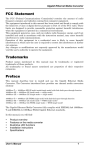
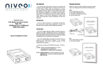
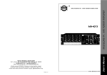
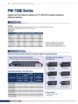
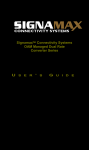
MAX COM
PRODUCT SPECIFICATIONS
Fiber Optic GIG-E, Video/Audio, HDTV Transceiver
Model MX1250V
HD TV
D
D
Description
The MX1250V multiplexes a Gigabit Ethernet
transceiver with a Video / Audio Multiplexer. The
Video/Audio multiplexer may be configured for one
baseband video and 4 channels of audio, two
baseband videos and 4 channels of audio or one
baseband video, 4 audio channels and one HDTV
channel.
The MX1250V can be configured to transmit over
one or two fiber strands.
The MX1250V has easy-to-read diagnostic LED's
for continuous status reports on network speed,
duplex media access control connection, and
network traffic.
The MX1250V uses standard SC or SC/APC fiber
optic connectors and is IEEE 802.3z 1000BASEFX compliant and operates with all devices that
adhere to this standard.
Features
•
•
•
•
•
•
•
•
1000Mbps Full Duplex Gigabit Ethernet Transceiver
One 1000BaseFX LAN Fiber Port (multimode or singlemode optics).
One 1000BaseFX WAN Fiber Port (singlemode optics 1310, 1550, CWDM, DWDM)
One Video Multiplexer Port configured for baseband video, baseband audio or HDTV channels
90 Km Transmission Range
1 or 2 Fiber Strand Transmission
Provide full wire-rate 2000Mbps Duplex Transmission for greater network performance
Plug-n-Play Gigabit Ethernet Mode Converter or Singlemode Repeater, IEEE 802.3z Compliant
Model Selection Guide
Model
Description
MX1250V-1S1V4AH-SCA-25
MX1250V-1S1V4AH-SCA-70
MX1250V-2S-1V4AH-SCA-60
MX1250V-2S-1V4AH-SCA-90
1000Base F.O. Gigabit Ethernet Transceiver, 1 Video, 4 Audio, 1 HDTV, 1 Fiber, SC/APC Connector, 25 Km
1000Base F.O. Gigabit Ethernet Transceiver, 1 Video, 4 Audio, 1 HDTV, 1 Fiber, SC/APC Connector, 70 Km
1000Base F.O. Gigabit Ethernet Transceiver, 1 Video, 4 Audio, 1 HDTV, 2 Fiber, SC/APC Connector, 60 Km
1000Base F.O. Gigabit Ethernet Transceiver, 1 Video, 4 Audio, 1 HDTV, 2 Fiber, SC/APC Connector, 90 Km
Other Connectors and Distances Available Upon Request
WAN Access Port:
Singlemode Fiber
Rear Panel
Audio
Video
G
G
HDTV
LAN
G
3
4
OUT
WAN
IN
+I+I
2
+I+I
1
G
Baseband
Video and
Audio I/O
TX
LINK
HDTV Port:
ASI or SMPTE-310M
1
0
RX
90 - 240 VAC
47 - 63 Hz
LAN Access Port:
Multimode Fiber or
Singlemode Fiber
IEC Power
Input Connector
Standards
IEEE 802.3z 1000BASE-FX Gigabit Ethernet
Connection Ports
Video: NTSC, PAL, SECAM
2 Port Port Fiber Transceiver: SC/PC or SC/APC
Video: BNC, 75Ohm, Audio: Terminal Block, HDTV: BNC
Video Specifications
SNR > 67 dB, dP < 1 degree, dG < 1%
Network Media
62.5/125 microns multi-mode Fiber cable
9/125 micron singlemode fiber cable.
LED indicators
Power, Link
Physical Dimensions
Environment
17” x 10" x 1.75”
Temperature: Operating: 0C to 50C
Storage: -20C to 70C
Humidity:
Operating: 10% to 90% RH
Storage: 5% to 90% RH
Voltage: 110/220V Auto-sense Internal Power, USA
Input Power Requirements:
Package Includes
•
•
•
•
Two Port 1000Base Gigabit Ethernet Transceiver and Video/Audio/HDTV Multiplexer (Various Configurations)
Power Cord
Rack-mountable hardware
Easy to follow owner's manual
System Requirements
•
IEEE 802.3z 1000BaseFX Gigabit Ethernet
Warranty
•
5 year limited warranty
MAXCOM
711 S. Carson St.
Carson City, NV 89701
Tel: (800) 493-2167
Fax: (209) 333-0388
User’s Manual
M X 1250V
G igabit Etherne t & A udio V ideo Fiber O ptic Transceiver
Installation and User Guide
P a ge
1
M X 12 50 V S eries U ser’s M anu al N o: U M -M X 1 2 50 V -D 0 9
TABLE OF CONTENTS
1
SAFETY INSTRUCTIONS
2
INTRODUCTION
2.1
2.2
2.3
3
INSTALLATION
3.1
3.2
3.3
3.4
3.5
3.6
3.7
3.8
3.9
4
System Description
Front Panel Indicator Description
Rear Panel Indicator Description
General Installation
Power Connection
Fiber Optic Cables Connection
Module Insertion and Removal
VX12 / VX24 Module Video Connections
VX12 / VX24 Module Audio Connections
Balanced Audio Connections
Unbalanced Audio Connections
External 4.5Mhz Audio Sub-Carrier (VX24 Modules only)
OPERATION
F ib e r O p tic C o m m u n ic a tio n s
P a ge
2
M X 12 50 V S eries U ser’s M anu al N o: U M -M X 1 2 50 V -D 0 9
1
SAFETY INSTRUCTIONS
THE 1250v SYSTEM MAY CONTAIN A CLASS IIIb LASER. PLEASE OBSERVE THE
FOLLOWING SAFETY PRECAUTIONS THAT APPLY TO LASER EQUIPPED UNITS.
WARNING: Do not disconnect the fiber optic external connector with the power turned
on. Exposure to Class IIIb Laser radiation is possible when the external fiber connector
is disconnected while the unit is still powered up. Ensure the rubber boot is in place
whenever the fiber optic cable is disconnected.
CAUTION: Attempting to make adjustments or performing operations other than those
specified may result in hazardous radiation exposure. Exposure for only seconds can
cause permanent eye damage as well as other injuries.
F ib e r O p tic C o m m u n ic a tio n s
P a ge
3
M X 12 50 V S eries U ser’s M anu al N o: U M -M X 1 2 50 V -D 0 9
2
INTRODUCTION
2.1
Module Description
The 1250v Series is a 1000BaseTX to 1000BaseFX converter. The 1250v Series
modules can be configured for multimode, singlemode, WDM or CWMD applications
Depending on the distance requirements between sites, the 1250vs may be equipped to
operate over multimode or single mode fiber. Distances between the transmitter and
receiver can be up to 3 Km for multimode operation and up to 120 Km for single mode
operation.
F ib er O p tic C o m m u n ic a tio n s
P a ge
4
M X 12 50 V S eries U ser’s M anu al N o: U M -M X 1 2 50 V -D 0 9
Models Numbers:
1250V-FF-(RJ45)-NV-MA-CCC-DDD-YYYY
1250V:
1000Base-FX / Video & Audio Media Converter Module.
FF
WAN Port Fiber Count / Fiber Type
1S
1 Singlemode Fiber
2S
2 Singlemode Fibers
2M
2 Multimode Fibers
RJ45
1000BaseTX to Fiber Media Converter (Option)
NV
Video Channels
MA
Audio Channels
CCC
WAN Port Fiber Optic Connector Type
SC
SC/PC (Blue)
SCA
SC/APC (Green)
FC
FC/PC
FCA
FC/APC
ST
ST
DDD
WAN Port Distance in Kilometers
YYYY
WAN Port Fiber Optic Wavelength,
850
850nm, Multimode
1310
1310nm Singlemode
1550
1550nm Singlemode
1470 – 1610nm
CWDM Wavelength
or DWDM Wavelength
F ib e r O p tic C o m m u n ic a tio n s
P a ge
5
M X 12 50 V S eries U ser’s M anu al N o: U M -M X 1 2 50 V -D 0 9
2.2 Gigabit Ethernet Module Front Panel Indicators
The following diagram depicts the front panel indicators:
L in k Indicator:
LN K F – O ptical F iber L ink O K
LN K C – 1 0 00 B aseT (R J4 5 ) L in k O K
L in k Indicator:
TX
D ata T ran sm itted
RX
D ata R eceived
F D X /C O L F ull D up lex / C ollision
LAN Port
1000Base-T I/O (RJ45)
Removable Modules:
F ib e r O p tic C o m m u n ic a tio n s
P a ge
6
M X 12 50 V S eries U ser’s M anu al N o: U M -M X 1 2 50 V -D 0 9
Video Module Front Panel Indicators
G
A udio
1
+
-
2
+
-
3
+
-
4
+
-
G
V ID 1
V ID 2
P W RL IN K
Module Power Status
LED GREEN = OK
LED OFF = No Power
Fiber Optic Link Status (Light on)
TX – Transmitter Status: OK
RX – Optical Link OK
P a ge
7
M X 12 50 V S eries U ser’s M anu al N o: U M -M X 1 2 50 V -D 0 9
2.3 Rear Panel Features
The following diagram depicts the rear panel features:
MX 1250v Rear Panel
On / Off Switch
P a ge
8
AC Power Connector
M X 12 50 V S eries U ser’s M anu al N o: U M -M X 1 2 50 V -D 0 9
3
INSTALLATION
3.1
General Installation
We strongly suggest that you install the chassis first, as this is more convenient for you to install media converters into the
chassis with ease. The accessories supplied in the product package includes: rackmount screws, rackmount brackets, and
bracket screws.
This well-built chassis can be installed in the following ways:
Mounted to 19-inch standard rack
Use the rackmount brackets and screws to install the chassis into any EIA 19” standard rack.
Step 1: Attach the brackets to each side of the chassis. Apply screws to each side and secure them tightly.
Step 2: Carefully position the chassis into the rack. Align the brackets to the side holes on the rack and use rack screws to
secure the chassis with the rack.
Step 3: Proceed to the “Connecting to Power” section.
Desktop or any flat surface
The chassis can sit on desktop or any flat surface with adequate space and ventilation. If you want to place it onto a shelf,
make sure the shelf can withstand a minimum weight of 10kg.
Step 1: Simply put the chassis on the desired place.
Step 2: Ensure the chassis receives good ventilation.
Step 3: Proceed to the “Connecting to Power” section.
3.2 Connecting to power
Step 1:Connect the supplied AC power cord to the receptacle on the power
supply.
Step 2:Attach the plug into a standard AC outlet with a voltage range from
100~240Vac.
Step 3: Turn on the chassis system by flipping the ON/OFF switch beside the receptacle to ON position.
The LEDs on the front panel of the media converter chassis system will come on then.
P a ge
9
M X 12 50 V S eries U ser’s M anu al N o: U M -M X 1 2 50 V -D 0 9
3.3
Fiber optic cable connection
Verify that the fiber cable meets the VX12T/R Series’ transmission requirements. Relevant
cable specifications include loss, distance (dispersion) and return loss.
3.4 Module Removal and Insertion
The VX12T/R modules may be removed and inserted for module upgrade of maintenance.
Module are removed by simply unfastening the thumb screws, slipping the module out of the
slot about 2 inches past the slot and remove the internal fiber connection. Use common
sense and care when removing and inserting modules.
To Insert a module, orient the module close to the slot, connect the fiber connector to the
optical module , slide the card into the slot and fasten the thumb screws.
For TX units, connect the internal fiber to the optical module port labeled TX. For RX units,
connect the internal fiber to the port indicated by the ARROW on the optical module.
WARNING: Failing to properly remove the internal fiber connection may break the fiber
and render the slot unusable.
The picture below shows the module removed from the chassis:
Internal Fibers
P a ge
10
M X 12 50 V S eries U ser’s M anu al N o: U M -M X 1 2 50 V -D 0 9
3.5
VX12 / VX24 Module Video Connections
Video signals are sent over a 75 ohm coax cable terminated in a BNC
connector (e.g. RG 59U with a BNC connector)
a. At the TX end (VX12T), connect the video source to the VIDEO BNC
connector.
b. At the RX end (VX12R), connect the VIDEO BNC to monitor. The output video
level may be adjusted by using a small screwdriver to turn the screw above the
output video connector, as shown below:
G
A udio
1
+
-
2
+
-
3
+
-
4
+
-
G
V ID 1
V ID 2
P W RL IN K
Audio I/O Connector
Video Adjust Potentiometer
(RX Only)
Video I/O Connector:
75 Ohm, BNC
P a ge
11
M X 12 50 V S eries U ser’s M anu al N o: U M -M X 1 2 50 V -D 0 9
3.6
Audio Connection
The VX12T/R Models have either simplex or duplex audio. The VX12T/R supports
both balanced audio and unbalanced audio.
Accessing the audio I/O requires
connecting to one or both channels of audio. The audio input and output impedance
is 10Kohms.
The Audio Terminal Block on the Video/Audio module provides the connectivity for
transmitting and receiving audio. The illustrations below show how to connect
balanced and unbalanced audio:
VX12T/R Audio Terminal Block Plug mates with the VX12T/R’s Audio Jack:
Inserting wires into the VX12T/R Audio Terminal Block:
Terminal Block Pin Out:
Pin
Assignm ents
1 3 5 7 9 11
2 4 6 8 10 12
P a ge
12
M X 12 50 V S eries U ser’s M anu al N o: U M -M X 1 2 50 V -D 0 9
3.7
Balanced Audio (Differential)
For Balanced audio connections, connect the audio “+” lead to the respective audio
channel “+” input and the “-“ lead to the audio channel “-‘ lead, as shown below.
G
A u d io
1
+
-
2
+
-
3
+
-
4 G
+
-
VID 1
VID 2
P W R L IN K
B alanced A udio Input & O utput C onnections
A u d io C h ann el 1 (+ ) L ead
C onn ect G round to T B P in 1
C onn ect Input + to T B P in 3
C o nn ect Inp u t – to TB P in 4
A u d io C h an n el 2
C onn ect Input + to T B P in 5
C o nn ect Inp u t – to TB P in 6
C onn ect G round to T B P in 2
A u d io C h an n el 3
C onn ect Input + to T B P in 7
C o nn ect Inp u t – to TB P in 8
C onn ect G round to T B P in 11
A u d io C h an n el 2
C onn ect Input + to T B P in 9
C o nn ect Inp u t – to TB P in 10
C onn ect G round to T B P in 12
P a ge
13
M X 12 50 V S eries U ser’s M anu al N o: U M -M X 1 2 50 V -D 0 9
3.8
Unbalanced Audio (Single Ended)
For Unbalanced audio connections, connect the audio I/O to the respective “+” and
“GND“ leads on the output audio connector, as shown below.
G
A u d io
1
+
-
2
+
-
3
+
-
4 G
+
-
VID 1
VID 2
P W R L IN K
U nbalanced A udio Input & O utput C onnections
A u d io C h ann el 1 (+ ) L ead
C onn ect G round to T B P in 1
C onn ect Input + to T B P in 3
A u d io C h an n el 2
C onn ect Input + to T B P in 5
C onnect G round to T B P in 2
A u d io C h an n el 3
C onn ect Input + to T B P in 7
C onn ect G round to T B P in 11
A u d io C h an n el 2
C onn ect Input + to T B P in 9
C onn ect G round to T B P in 12
Note: Unbalanced Audio output will be 3dB less than input
Note: DO NOT connect the (-) lead to ground on the audio OUTPUT as this may
create noise on the ground, which may distort the video signals.
P a ge
14
M X 12 50 V S eries U ser’s M anu al N o: U M -M X 1 2 50 V -D 0 9
3.9
External 4.5Mhz Audio Sub-Carrier
The VX12T/R Series also includes an option for transmitting video, audio and a 4.5Mhz
audio sub-carrier as an external signal. The figure below depicts the VX12T/R set up with
video, 4 channels of baseband audio and an external audio sub-carrier channel. The audio
sub-carrier channel uses a BNC connector with 75 ohm impedance.
G
A udio
1
+
-
2
+
-
3
+
-
4 G
+
-
VID1
VID2
P W RL IN K
Baseband Audio I/O
Video I/O
BNC
75 Ohm
External Audio Sub-Carrier I/O
BNC Connector
75 Ohm
P a ge
15
M X 12 50 V S eries U ser’s M anu al N o: U M -M X 1 2 50 V -D 0 9
4
Operation
Turn-On Procedure
To operate the 1250V Gigabit Ethernet Modules system:
1. Install the MX5000GE module, if necessary
2. Connect the 1000Base-TX Gigabit Ethernet to the Module
3. Install the fiber optic cables to the 1250v
4. Verify that the PWR and LNKF and LNKC are illuminated. This indicates
that the unit has a good optical and 1000BaseT link.
5. Verify that the VX12T Video Module Power and LINK status = GREEN
6. Verify that the VX12R Video Module Power and LINK status = GREEN
7. Connect VIDEO INPUT(s) to VX12T BNC IN Connectors
8. Connect AUDIO INPUTs to the VX12T Terminal Block
9. Verify that Video and Audio are being received at the VX12R
P a ge
16