1
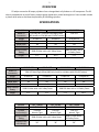
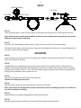
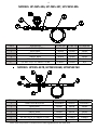
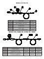
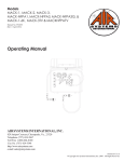
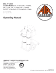
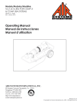
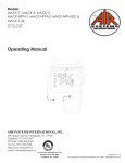
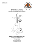
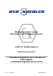
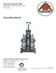
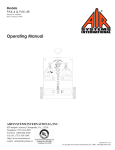
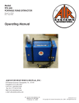
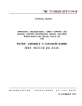
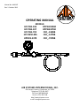
Manual No. WHP007
Rev. 3 October 2012
OPERATING MANUAL
MODELS:
HP-FW5-346
HPFW10346R
HP-FW5-347
HPFW53476K
HP-FW5-702
CBF_-346NB
HP-FW50-MA
CBF_-347NB
HPFW5-347R
CBF_-702NB
Air Systems International, Inc.
829 Juniper Crescent, Chesapeake, Va, 23320
Telephone (757) 424-3967
Toll Free 1-800-866-8100
Fax No. (757) 424-5348
http://www.airsystems.com
e-mail: [email protected]
2
OVERVIEW
Fill whips are used to fill empty cylinders from a charged bank of cylinders or a fill compressor. The fill
whip is provided with an on/off valve, pressure gauge, bleed valve, and a hand-tight nut. Some models include
a preset relief valve to eliminate the possibility of overfilling cylinders.
SPECIFICATIONS
Model #
HP-FW5-346
HPFW10346R
HP-FW5-702
Bottle Fill
CGA-346/347 Universal Hand-tight (Gold)
CGA-702
Connection
(Will install on CGA-346 and CGA-347 Valves)
Gauge
0-5000 PSI
0-5000 PSI
0-10,000 PSI
ON/OFF Valve
Yes
Yes
Yes
Bleed Valve
Yes
Yes
Yes
Relief Valve
No
Yes*
No
Whip Pressure
6000 PSI Max. with a
5000 PSI Max. with a 4:1 Safety Factor
Rating
4:1 Safety Factor
Length
5 Ft.
10 Ft.
5 Ft.
* Relief valve set pressure is stamped on the lead tag attached to the relief valve.
Model #
HP-FW5-347
HPFW5-347R
HPFW53476K
HP-FW50-MA
Bottle Fill
CGA-347 Hand-Tight (Silver)(Will only install on cylinders with CGA-347 valves)
Connection
Gauge
0-5000 PSI
0-5000 PSI
0-5000 PSI
0-10,000 PSI
ON/OFF Valve
Yes
Yes
Yes
Yes
Bleed Valve
Yes
Yes
Yes
Yes
Relief Valve
No
Yes*
Yes*
No
Whip Pressure
5000 PSI Max. with a 4:1 Safety Factor
6000 PSI Max. with a 4:1 Safety Factor
Rating
Length
5 Ft.
5 Ft.
5 Ft.
50 Ft.
* Relief valve set pressure is stamped on the lead tag attached to the relief valve.
Model #
Fill Whip
Cylinder
Connection(s)
Whip Pressure
Rating
Length of Connect Whip(s)
CBF_-346NB
HP-FW5-346
CGA-346
Wrench Tight
CBF_-347NB
HP-FW5-347
CGA-347
Wrench Tight
5000 PSI Max. with a 4:1 Safety Factor
30”
30”
CBF_-702NB
HPFW53476K
CGA-702
Wrench Tight
6000 PSI Max.with a
4:1 Safety Factor
30”
3
PRESSURE GAUGE
SETUP
1/4” PLUG
CGA CONN.
ON/OFF VALVE
SWIVEL FITTING
BLEED VALVE
STEP 1)
Close all cylinder valves. Locate the last cylinder in the system and remove the 1/4” MPT plug from the tee.
Note: All Air Systems’ cascade whip assemblies terminate with a tee fitting and a plug making it easy to add
additional connect whips or a fill whip.
STEP 2)
Install the 1/4” swivel fitting in place of the 1/4” plug. Connect the fill whip to the swivel fitting.
To install fill the fill whip on a fill compressor; locate the outlet fitting and install the 1/4” swivel fitting and connect the fill whip to the swivel fitting.
OPERATION
STEP 1)
Close the bleed valve and on/off valve by turning knobs clockwise. Install the CGA conection to the cylinder
valve of the cylinder to be filled.
STEP 2)
Cascade filling is accomplished by opening only the first cylinder of the cascade system. Allow pressure to
equalize in the cylinder being filled. Once equalized, close the first cylinder of the cascade system and repeat
with the second cylinder, and so on. This is the most efficient way to operate a fill assembly and maximize fills.
If filling from a compressor, start compressor now.
STEP 3)
Open the on/off valve on the fill whip to desired fill rate.
Caution: Do not fill at excessive rates!
STEP 4)
After the desired fill pressure has been obtained, close the on/off valve.
Note: Some models are equipped with a preset relief valve to prevent overfilling of cylinders. The relief pressure will be marked on a lead tag.
STEP 5)
Close the valve of the cylinder being filled and open the bleed valve.
STEP 6)
Remove the fill whip from cylinder by turning the CGA connection counterclockwise.
4
MODELS: HP-FW5-346, HP-FW5-347, HP-FW50-MA
ITEM #
1
2
3
4
5
6
DESCRIPTION
HAND-TIGHT NUT/STEM
BLEED VALVE
PRESSURE GAUGE
ON/OFF VALVE
REPLACEMENT WHIP
1/4” MPT X 1/4” FPT SWIVEL FITTING
HP-FW5-346 HP-FW5-347
SS347HT
SS347SNHT
VAL030
VAL030
GA255KSBOT GA255KSBOT
VAL020
VAL020
HP-FW5-RW HP-FW5-RW
ST44MFV
ST44MFV
HP-FW50-MA
SS347SNHT
VAL030
GA2510KS
VAL020
PHA50650MJ
N/A
MODELS: HPFW5-347R, HPFW10346R, HPFW53476K
ITEM #
DESCRIPTION
HPFW5-347R HPFW10346R
1
HAND-TIGHT NUT/STEM
SS347SNHT
SS347HT
2
BLEED VALVE
VAL030
VAL030
3
PRESSURE GAUGE
GA255KSBOT GA255KSBOT
4
ON/OFF VALVE
VAL020
VAL020
5
CONNECT WHIP
HP-FW5-RW6 HP-FW10-RW
6
1/4” MPT X 1/4” FPT SWIVEL FITTING
ST44MFV
ST44MFV
7
RELIEF VALVE*
VAL050
VAL050
* Relief valve set pressure is stamped on the lead tag attached to the relief valve.
HPFW53476K
SS347SNHT
VAL030
GA256KS
VAL020
HP-FW5-RW6
ST44MFV
VAL050
5
MODELS: HP-FW5-702
ITEM #
1
2
3
4
5
6
7
DESCRIPTION
CGA-702 WRENCH TIGHT NUT
CGA-702 WRENCH TIGHT STEM
BLEED VALVE
PRESSURE GAUGE
ON/OFF VALVE
CONNECT WHIP
1/4” MPT X 1/4” FPT SWIVEL FITTING
HPFW5-702
SS702N
SS702S
VAL030
GA2510KS
VAL020
HP-FW5-RW6
ST44MFV
MODELS: CBF_-346NB, CBF_-347NB, CBF_-702NB
ITEM #
DESCRIPTION
CBF_-346NB
CBF_-347NB
CBF_-702NB
1
2
3
4
4A
FILL WHIP ASSEMBLY
CGA WRENCH TIGHT NUT
CGA WRENCH TIGHT STEM
30” WHIP, 1/4” MPT X 1/4” MPT
30” WHIP ASSEMBLY, INCLUDES 30” WHIP,
TEE, AND CGA CONNECTION
HP-FW5-346
HPBR025
HPBR026
PHA050-30M
HP-FW5-347
HPBR049
HPBR050
PHA050-30M
HPFW53476K
SS702N
SS702S
PHA506K30M
CW-30
CW-30HP
CW-30-702
6
HIGH PRESSURE AIRLINE MAINTENANCE AND INSPECTION
Monthly
Annually
Every 4 years
Check regulators, gauges, and valves for external leakage.
Inspect valves for proper closure.
Check whips for flexibility, wear, leakage, blisters or other hose damage.
Inspect check valves for leakage.
Check relief valve’s pressure setting.
Check regulator function by opening and closing regulator knob fully.
Replace all flexible whips.
7
WArrAnty DiSclAimer
Air Systems’ manufactured equipment is warranted to the original user against defects in workmanship or materials under normal use for one year from the date of purchase. Any part which is determined by Air Systems
to be defective in material or workmanship will be, as the exclusive remedy, repaired or replaced at Air Systems’ option. This warranty does not apply to electrical systems or electronic components. Electrical parts are
warranted, to the original user, for 90 days from the date of sale. During the warranty period, electrical components will be repaired or replaced at Air Systems’ option.
no otHer WArrAnty, eXPreSSeD or imPlieD, AS to DeScriPtion, QUAlity, mercHAntABility, FitneSS
For A PArticUlAr PUrPoSe, or Any otHer mAtter iS GiVen By Air SyStemS in connection HereWitH. UnDer no circUmStAnceS SHAll tHe Seller Be liABle For loSS oF ProFitS, Any otHer Direct
or inDirect coStS, eXPenSeS, loSSeS, or DAmAGeS AriSinG oUt oF DeFectS in, or FAilUre oF tHe
ProDUct or Any PArt tHereoF.
The purchaser shall be solely responsible for compliance with all applicable Federal, State and Local OSHA and/
or MSHA requirements. Although Air Systems International believes that its
products, if operated and maintained as shipped from the factory and in accordance with our “operations
manual”, conform to OSHA and/or MSHA requirements, there are no implied or expressed warranties of such
compliance extending beyond the limited warranty described herein. Product designs and specifications are
subject to change without notice. Rev. 2, 12/98
Air leaks are not covered under warranty except when they result from a defective system component, i.e. an
on/off valve or regulator or upon initial delivery due to poor workmanship. Air leaks due to poor delivery or
damage will be covered under delivery claims. Minor air leaks are part of routine service and maintenance and
are the responsibility of the customer just as are filters and oil changes.
Air SyStemS internAtionAl, inc.
829 Juniper Crescent, Chesapeake, Va, 23320
Telephone (757) 424-3967
Toll Free 1-800-866-8100
Fax No. (757) 424-5348
http://www.airsystems.com
e-mail: [email protected]
Printed in the U.S.A. ©Copyright Air Systems International, Inc. 2012 All Rights Reserved