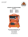
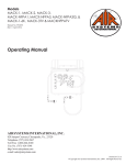
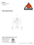
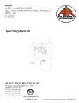
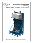
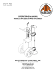
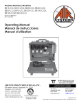
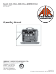
1
EAC-97 SERIES
Covers Models EAC-97ENB, EAC-97HENB,
EAC-97NB, EAC-97PENB, EAC-97PHNB,
EAC97PHENB, EAC-97PTNB & EAC-97HNB
Manual No. ERGO009
(Rev 0 September 2006)
Operating Manual
AIR SYSTEMS INTERNATIONAL, INC.
829 Juniper Crescent, Chesapeake, Va. , 23320
Telephone (757) 424-3967
Toll Free 1-800-866-8100
Fax No. (757) 424-5348
http://www.airsystems.cc
e-mail: [email protected]
Printed in U.S.A
©Copyright Air Systems International, Inc. 2006. All Rights Reserved.
-2-
OVERVIEW
The Ergo-Air Cart is an ergonomically designed mobile cylinder cart for long duration
breathing air applications. The unique design helps reduce back/shoulder injuries and
allows movement by people of small stature. Low pressure warning alarm is standard.
Deck mounted hose reels and storage cabinets are just a few of the options available.
®
SPECIFICATIONS FOR
MODELS EAC-97ENB, EAC-97HENB, EAC-97PENB & EAC97PHENB
Cart Dimensions
Weight without
Cylinders
Frame
Cylinder Straps
Wheels/Casters
Whip Assemblies
Bleeder Valves
Check Valves
Warning Alarm
Primary Regulator
Pressure
(Model EAC-97ENB &
EAC-97PENB)
Primary Regulator
Pressure
(Model EAC-97HENB &
EAC97PHENB)
Primary Regulator
Flow Rate
Relief Valve
Air Distribution
Transportation
Ergo Design
32"W x 55"H x 38¼" D
(81cm W x 140cm H x 97cm D)
250 lbs (114 kg)
Steel Powder Coated
Four (4) adjustable straps to accommodate
different size cylinders
Standard: 16" semi-pneumatic (front)
6" soft tread swivel casters with brake (rear)
Optional: 16" pneumatic (front)
10" pneumatic casters with brake (rear)
Thermo plastic 5000psi (345 bar) rated 4:1
safety factor
Allows depressurization of hand tight nut before
cylinder removal. Model EAC-97HENB only
Allows independent cylinder operation and removal
without complete system shutdown.
9 VDC audible and visual alarms for low pressure warning
Set at approximately 500psi (34.5 bar)
0-3000 psi (205 bar) inlet
0-125psi (8.6 bar) discharge
0-5500psi (379 bar) inlet
0-125psi (8.6 bar) discharge
80cfm (2260 LPM) @ 125psi (8.6 bar) discharge pressure
125psi (8.6 bar) ASME preset
Four (4) regulated quick connect fittings
2 eyelets for sling attachment--vertical lifting
Raising Cart: 15lbs. of force
Lowering Cart: 35lbs. of force
-3-
PARTS IDENTIFICATION
MODELS EAC-97ENB, EAC-97HENB, EAC-97PENB & EAC97PHENB
Models
EAC-97ENB & EAC-97PENB
Models
EAC-97HENB & EAC-97PHENB
ITEM #
1
1A
2
2A
3
3A
4
5
5A
6
7
8
9
10
11
12
13
14
15
16
17
18
19
20
21
22
23
DESCRIPTION
RESPIRATOR COUPLING, HANSEN
RESPIRATOR COUPLING, SCHRADER
DUST CAP, HANSEN
DUST CAP, SCHRADER
PRESSURE REGULATOR, 3000 PSI (EAC-97ENB, EAC-97PENB)
PRESSURE REGULATOR, 5000 PSI (EAC-97HENB, EAC-97PHENB)
PRESSURE GAUGE, 0-200 PSI
PRESSURE GAUGE, 0-4000 PSI
PRESSURE GAUGE, 0-6000 PSI
LOW PRESSURE ALARM ON/OFF SWITCH
STORAGE BOX
CYLINDER STRAP
CGA-346 NUT (EAC-97ENB, EAC-97PENB)
CGA-346 STEM WITH CHECK VALVE (EAC-97ENB, EAC-97PENB)
BLEEDER VALVE (EAC-97HENB, EAC-97PHENB)
CGA-347 HAND-TIGHT (EAC-97HENB, EAC-97PHENB)
16" WHEEL, SEMI-PNEUMATIC
16" WHEEL, PNEUMATIC (EAC-97PENB & EAC-97PHENB)
5" CASTER
BRAKE KIT FOR 5" CASTER
10" PNEUMATIC CASTER (EAC-97PENB & EAC-97PHENB)
12 VDC BULB
RED LENS
AUDIBLE ALARM
REMOTE ALARM JACK
REMOTE ALARM JACK COVER
BATTERY HOLDER
PART #
QDH3SL6M
QDSSL6M
QDH3DCAP
QDSDCAP
REG-3000
REG-5000
GA25200SRG
GA254KSREG
GA256KSREG
ELSW005
EAC-97SBU
HDWR113B
HPBR025
HPBR027
VAL030
SS347HT
HDWR145
HDWR120
HDWR122
HDWR122A
HDWR101
ELDS001
ELDS005
ELLS004
ELJP004
ELJP005
MONC006
-4-
SETUP FOR MODELS MODELS EAC-97ENB,
EAC-97HENB, EAC-97PENB & EAC97PHENB
Step 1)
Remove clevis pin. Push the handle up and forward to situate the cart in an upright position. Reinstall the clevis pin.
Step 2)
Install, arrange and index the air cylinders so that the valve outlets are facing away from the control panel. Secure cylinders
by tightening the straps at the buckle and mating the velcro sections.
Step 3)
Model EAC-97HENB & EAC-97PHENB: Install CGA-347 hand tight nuts on the cylinder valves, and tighten. Insure
both bleeder valves are closed by turning fully clockwise.
Model EAC-97ENB & EAC97PENB: Install CGA-346 wrench tight nuts on the cylinder valves, and tighten.
Step 4)
Place the “on/off” toggle switch to the “on” position. The lights and alarms should should. Note: The alarm preset to
sound at approximately 500psi (35 bar) descending pressure. If alarms do not activate, replace the 9-volt batteries.
Step 5)
LOW PRESSURE ALARM TEST
Make sure the bleeder valves are closed; open one cylinder:
a. At this time the alarm should shut off when system pressure reaches 500psi (35bar) or greater.
b. Check the cylinder pressure on the high pressure gauge.
c. Set required respirator pressure with the regulator control knob
d. Close the cylinder valve and slowly bleed off pressure through one of the respirator outlets.
e. The low pressure alarm should sound and the light should come on at approximatly 500psi (35 bar).
f. Open the other cylinder and check its pressure on the high pressure gauge.
Step 6)
Couple respirators and lengths of hoses to the manifold, and readjust regulator control knob if necessary. The system is
now operational. When a cylinder in use has been depleted to approximately 500psi (35 bar), the low
pressure warning alarm will sound, indicating that the cylinder needs to be replaced.
Optional)
A variety of hose reel options are available. If the lower reel is to be used, open the valve located near the inlet. This will
pressurize the hose reel.
To change a cylinder while the cart is still in use:
a. Open the second cylinder and note the gauge pressure to assure that the cylinder is full.
b. Close the drained cylinder and open the bleeder valve (high pressure version) on the whip to relieve the
remaining pressure on the hand tight nut.
c. The system's check valves will prevent back flow from the other cylinder in use
d. Replace or fill the drained cylinder and reinstall connecting whip.
-5-
SETUP FOR MODELS EAC-97ENB,
EAC-97HENB, EAC-97PENB & EAC97PHENB
-6-
SPECIFICATIONS FOR
MODELS EAC-97NB, EAC-97HNB, EAC-97PTNB, & EAC-97PHNB
Cart Dimensions
Weight without
Cylinders
Frame
Cylinder Straps
Wheels/Casters
Whip Assemblies
Bleeder Valves
Check Valves
32"W x 55"H x 38¼" D
(81cm W x 140cm H x 97cm D)
250 lbs (114 kg)
Steel Powder Coated
Four (4) adjustable straps to accommodate
different size cylinders
Standard: 16" semi-pneumatic (front)
6" soft tread swivel casters with brake (rear)
Optional: 16" pneumatic (front)
10" pneumatic casters with brake (rear)
Thermo plastic 5000psi (345 bar) rated 4:1
safety factor
Allows depressurization of hand tight nut before
cylinder removal. Model EAC-97HENB only
Allows independent cylinder operation and removal
without complete system shutdown.
Pneumatic whistle alarms for low pressure warning
Set at approximately 500psi (34.5 bar)
Warning Alarm
Primary Regulator
Pressure
(Model EAC-97NB & EAC0-3000 psi (205 bar) inlet
97PTNB)
0-125psi (8.6 bar) discharge
Primary Regulator
Pressure
(Model EAC-97HNB &
0-5500psi (379 bar) inlet
EAC-97PHNB)
0-125psi (8.6 bar) discharge
Primary Regulator
Flow Rate
80cfm (2260 LPM) @ 125psi (8.6 bar) discharge pressure
Relief Valve
125psi (8.6 bar) ASME preset
Air Distribution
Four (4) regulated quick connect fittings
Transportation
2 eyelets for sling attachment--vertical lifting
Raising Cart: 15lbs. of force
Lowering Cart: 35lbs. of force
Ergo Design
-7-
PARTS IDENTIFICATION
MODELS EAC-97NB, EAC-97HNB, EAC-97PTNB, & EAC-97PHNB
ITEM #
DESCRIPTION
PART #
1
RESPIRATOR COUPLING, HANSEN
QDH3SL6M
1A
RESPIRATOR COUPLING, SCHRADER
QDSSL6M
2
DUST CAP, HANSEN
QDH3DCAP
2A
DUST CAP, SCHRADER
QDSDCAP
3
PRESSURE REGULATOR, 3000 PSI (EAC-97NB)
REG-3000
3A PRESSURE REGULATOR, 5000 PSI (EAC-97HNB)
REG-5000
4
PRESSURE GAUGE, 0-200 PSI
GA25200SRG
5
PRESSURE GAUGE, 0-4000 PSI
GA254KSREG
5A
PRESSURE GAUGE, 0-6000 PSI
GA256KSREG
6
LOW PRESSURE WHISTLE
AC-PA25
7
CYLINDER STRAP
HDWR113B
8
CGA-346 STEM WITH CHECK VALVE
HPBR027
9
CGA-346 NUT
HPBR025
10
BLEEDER VALVE
VAL030
11
CGA-347 HAND-TIGHT
SS347HT
12
16" WHEEL, SEMI-PNEUMATIC
HDWR145
13
16" WHEEL, PNEUMATIC
HDWR120
14
5" CASTER
HDWR122
15
BRAKE KIT FOR 5" CASTER
HDWR122A
16
10" PNEUMATIC CASTER
HDWR101
-8-
SETUP FOR MODELS EAC-97NB, EAC-97HNB,
EAC-97PTNB, & EAC-97PHNB
Step 1)
Remove clevis pin. Push the handle up and forward to situate the cart in an upright position. Reinstall the clevis pin.
Step 2)
Install, arrange and index the air cylinders so that the valve outlets are facing away from the control panel. Secure cylinders
by tightening the straps at the buckle and mating the velcro sections.
Step 3)
Model EAC-97HNB: Install CGA-347 hand tight nuts on the cylinder valves, and tighten. Insure both bleeder valves are
closed by turning fully clockwise.
Model EAC-97NB: Install CGA-346 wrench tight nuts on the cylinder valves, and tighten.
Step 4)
Open one cylinder. At this time the low pressure warning alarm will sound, until it sets itself at approximately 1000psi (69
bar). Check reading on gauge to verify that it is full. Close the cylinder.
Step 5)
Set required respirator pressure with the regulator control knob, and bleed pressure by partially engaging a male plug into
one of the respirator fittings. This despressurizes the manifold, and simulates low cylinder pressure. The low pressure
warning alarm should sound at approximately 500psi (35 bar).
Step 6)
Open the second cylinder. At this time the low pressure warning alarm will resound until it sets itself at approximately
1000psi (69bar). Check reading on gauge to verify that it is full.
Step 7)
Couple respirators and lengths of hoses to the manifold, and readjust regulator control knob if necessary. The system is
now operational. When a cylinder in use has been depleted to approximately 500psi (35 bar), the low
pressure warning alarm will sound, indicating that the cylinder needs to be replaced.
Optional)
A variety of hose reel options are available. If the lower reel is to be used, open the valve located near the inlet. This will
pressurize the hose reel.
To change a cylinder while the ERGO-AIR® CART is still in use:
1. Open second cylinder and note the gauge pressure to assure that it is full.
2. Close the drained cylinder.
3. Model EAC-97HNB & EAC-97PHNB: Open the bleeder valve of the drained cylinder.
Remove CGA-347 hand tight nut. Replace with full cylinder. Reinstall connect whip. Close
bleeder valve.
Model EAC-97NB & EAC-97PTNB: Loosen CGA-346 wrench tight nut to relieve
pressure. Replace with a full cylinder. Reinstall connect whip.
Note: The system is equipped with check valves that will prevent back flow from the other
cylinder in use.
-9-
SETUP FOR MODELS EAC-97NB, EAC-97HNB,
EAC-97PTNB, & EAC-97PHNB
-10-
HIGH PRESSURE AIRLINE GENERAL MAINTENANCE & INSPECTION
FOR ALL MODELS
Monthly
1. Check regulators, gauges, and valves for external leakage.
2. Inspect cylinder valves for proper closure.
3. Check cylinder pigtails for cleanliness, flexibility, wear, leakage, blisters on hose, thread
damage, and O-rings on CGA fittings. Replace damaged items immediately.
Annually
1. Check relief valve’s pressure setting.
2. Check regulator function by opening and closing regulator valve knob fully.
Every 4 years
1. Replace all flexible pigtails.
SHUTDOWN FOR ALL MODELS
Make sure all personnel have egressed the hazardous area and have disconnected from the breathing air system.
1. Close cylinder valves.
2. Depressurize manifold pressure by partially engaging male plug into one of the respirator fittings.
3. Close the regulator by turning the control knob counterclockwise.
4. Reinstall dust caps.
5. Remove connections from cylinders. Reinstall cylinder valve covers (if applicable).
6. If transportation of cart is required, remove clevis pin, place foot on base and pull handle
until movement stops. Replace clevis pin.
-11-
Warranty Disclaimer
Air Systems’ manufactured equipment is warranted to the original user against defects in workmanship or materials under normal use for one year after date of purchase. Any part which is determined by Air Systems to be defective in material or workmanship will be, as the exclusive remedy,
repaired or replaced at Air Systems’ option. This warranty does not apply to electrical systems or
electronic components. Electrical parts are warranted, to the original user, for 90 days from the
date of sale. During the warranty period, electrical components will be repaired or replaced at Air
Systems’ option.
NO OTHER WARRANTY, EXPRESSED OR IMPLIED, AS TO DESCRIPTION, QUALITY, MERCHANTABILITY, FITNESS FOR A PARTICULAR PURPOSE, OR ANY
OTHER MATTER IS GIVEN BY AIR SYSTEMS IN CONNECTION HEREWITH. UNDER NO CIRCUMSTANCES SHALL THE SELLER BE LIABLE FOR LOSS OF
PROFITS, ANY OTHER DIRECT OR INDIRECT COSTS, EXPENSES, LOSSES OR
DAMAGES ARISING OUT OF DEFECTS IN, OR FAILURE OF THE PRODUCT OR
ANY PART THEREOF.
The purchaser shall be solely responsible for compliance with all applicable Federal, State and
Local OSHA and/or MSHA requirements. Although Air Systems International believes that its
products, if operated and maintained as shipped from the factory and in accordance with our “operations manual”, conform to OSHA and/or MSHA requirements, there are no implied or expressed
warranties of such compliance extending beyond the limited warranty described herein. Product
designs and specifications are subject to change without notice. Rev 2 12/98
Air leaks are not covered under warranty except when they result from a defective system
component, i.e. an on/off valve or regulator or upon initial delivery due to poor workmanship. Air leaks due to poor delivery or damage will be covered under delivery claims. Minor
air leaks are part of routine service and maintenance and are the responsibility of the customer just as are filters and oil changes.