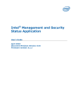
1
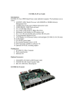
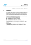
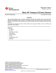
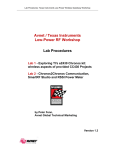
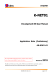
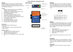
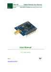
Core2530/XCore2530 User Manual share awesome hardware Core2530/XCore2530 User Manual CONTENTS 1. Introduction ..................................................................................................................................... 2 2. Zigbee network experiment ............................................................................................................. 4 3. 2.1. Roles in Zigbee network ...................................................................................................... 4 2.2. Bootloader ........................................................................................................................... 4 2.3. Firmware downloading ...................................................................................................... 10 2.4. Networking communicaiton .............................................................................................. 12 Working with PC ............................................................................................................................. 15 3.1. Introduction ....................................................................................................................... 15 3.2. AT commands .................................................................................................................... 15 Appendix................................................................................................................................................. 21 1 V2.2.2, April, 21st, 2015 Core2530/XCore2530 User Manual 1. share awesome hardware INTRODUCTION Core2530/XCore2530 is a Zigbee module developed by Waveshare, which adopts the CC2530 IC of TI as its main control chip. Comparing with Core2530, XCore2530 has a longer transmission distance by enhancing the power amplification function. This module can be used in two primary purposes: For application (Users only need to concentrate themselves on application development, since this module works as a underlying hardware in this case): The firmware provided with the module should be applied. Under this condition, the module would serve as a Zigbee wireless serial port. With the simple operations of the module, as easy as that of the serial port, you do not need to know much about the complex Zigbee protocol. For development (Users should perform a secondary development to the module for implementing the underlying application): You need to write the Zigbee communication protocol code by yourself. In this case, you should use the downloader, such as CC Debugger, and learn the Zigbee protocol. Features: Simple operations, as easy as that of the serial port; Self-networking (At least a coordinator and a router needed); Severe as a router in factory default setting (modifiable to a coordinator by downloading corresponding coordinator firmware); Support program download by serial port (the downloader is not required normally, since the firmware supports serial Bootloader); Support parameter configuration by PC software; RFX2401 power amplifier (XCore2530 only). 2 V2.2.2, April, 21st, 2015 Core2530/XCore2530 User Manual Core2530 share awesome hardware XCore2530 3 V2.2.2, April, 21st, 2015 Core2530/XCore2530 User Manual 2. share awesome hardware ZIGBEE NETWORK EXPERIMENT Zigbee network needs minimum a coordinator and a router. Since the Core2530/XCore2530 module has a built-in Bootloader in default setting, you can download the firmware to the module directly via the serial port. Notes: In the Zigbee network experiment, you may need to apply two pieces of Core2530/XCore2530 modules, and two pieces of ZB502/ZB600 baseboards. 2.1. ROLES IN ZIGBEE NETWORK 1. Coordinator Select a communication channel and a PAN ID to build a network; Allow other routers and end devices to join this network; Route the data in the network; Must be kept power supplying, and must not enter the SLEEP mode; Preserve data for the end devices entered SLEEP mode till them wake up and retrieve the data. 2. Router Must join a Zigbee network before performing data transmission; Allow other routers and end devices to join the network, after it joined one; Route the data in the network upon joining the network; Must be kept power supplying, and must not enter the SLEEP mode; Preserve data for the end devices entered the SLEEP mode till them wake up and retrieve the data. 3. End Device Must join a Zigbee network before performing data transmission; Not allow other devices to join the network; Transmit and receive data thought parent node, unable to route the data in the network; Support battery power supply and SLEEP mode. 2.2. BOOTLOADER 1. Introduction The built-in Bootloader enable users to download the program to the module directly via a serial port without using the CC Debugger. However, the CC Debugger is required in the course of programming 4 V2.2.2, April, 21st, 2015 share awesome hardware Core2530/XCore2530 User Manual the Bootloader into the module. For more detailed information, please refer to the Section How to program Bootloader. There are two different Bootloaders available for this module: bootloader.hex and bootloader_wait.hex. For easier understanding, we call the module with the bootloader.hex as module A, and the module with the bootloader_wait.hex as module B in this document. The module A will execute the valid program immediately, if any, in the Flash memory, after powered up. Otherwise, its LED1 will keep blinking indicating that there is no program in the Flash memory and you can download a new one via the serial port in this case. For module B, its LED1 and LED2 will blink alternately, if there is any valid program stored in the Flash memory, after powered up. Now, if you press the button KEY2, the module B will execute the program immediately; and if you press the button KEY1, the module B will enter the Bootloader mode under which you can download a new program to the module B. In case of no key-press action within 40 seconds after powered up, the module B will execute the program in the Flash memory automatically. When there is no valid program in the Flash memory, its LED1 will keep blinking, and you can download a new one via the serial port in this case. The module A with bootloader.hex is suitable for independent application, since it can run the program directly without any external key-press trigger. However, the module B with the bootloader_wait.hex should work with the baseboard ZB502/ZB600 for relative experiments and studies. By default, the bootloader_wait.hex is programmed to the module. 2. CC debugger driver installation Unzip the package CC-Debugger_Drivers.7z to the installation directory; Double click the software Setup_SmartRF_Drivers-1.2.0.exe for installation; Click the button Next, and select the installation path; 5 V2.2.2, April, 21st, 2015 Core2530/XCore2530 User Manual share awesome hardware Click the button Install, and wait till the installation finished. When finished, connect the CC Debugger to your PC, and open the option Device Manager in Windows. You may find the option CC Debugger if its driver is installed successfully. 6 V2.2.2, April, 21st, 2015 Core2530/XCore2530 User Manual share awesome hardware 3. How to program Bootloader Install the module to the baseboard, and connect the baseboard and the CC Debugger to your PC with the USB cables; Power up the baseboard, and press the RESET key on the CC Debugger. If the communication is built up successfully, the indicator on the CC Debugger will light up and turn to green, indicating that it is ready to download new programs; Open the SmartRF Studio7, and select the button Flash Programmer on the upper right of the software interface to open another window. 7 V2.2.2, April, 21st, 2015 Core2530/XCore2530 User Manual share awesome hardware Select the option Program CCxxxx Soc or MSP430 in the pulled-down menu What do you want to program?, and choose the image file you want to program within the Flash image box. Here, it is bootloader_wait.hex. And then, click the button Perform actions to start programming. 8 V2.2.2, April, 21st, 2015 Core2530/XCore2530 User Manual share awesome hardware When finished, there will be a message “Erase, program and verify OK” appears on the bottom of the window, and the LED1 of the baseboard will keep blinking indicating that program downloading is successful. 9 V2.2.2, April, 21st, 2015 Core2530/XCore2530 User Manual share awesome hardware 2.3. FIRMWARE DOWNLOADING In this section, we will illustrate how to build a Zigbee network by applying two groups of Core2530 + ZB600, one works as a coordinator and the other one works as a router. For easier understanding, we call the coordinator as Group A and the router as Group B. Connect the Group A and the Group B to your PC with the USB cables, respectively. And get their corresponding serial port numbers after powered up. If the firmware has been installed to the Group A or/and the Group B, the LED1 and the LED2 on the Core2530 module(s) will blink alternately after resetting. Pressing the button KEY1 to enter the Bootloader mode, you will see the LED1 keep blinking. When there is no firmware in the Core2530 module(s), the LED1 will keep blinking after powered up, which means the Core2530 module(s) has entered the Bootloader mode directly and there is no need to press the button KEY1 again. Start the software SBDemo.exe for firmware downloading. 10 V2.2.2, April, 21st, 2015 Core2530/XCore2530 User Manual share awesome hardware Enter the corresponding serial port of the Group A in the COM Port box, and click the button … to select the firmware file Coordinator.bin in the Image File box. Then, click the button Load Image to start downloading. For the Group B, select the firmware file Router.bin. The file download method is the same as that of the Group A. Start two serial debug assistants, and enter the serial port number of the Group A to one of the assistants and the port number of the Group B to the other one. Then, set the Baud rate: 38400, Data bit: 8 and Stop bit: 1; Reset the Group A, you can see the LED1 and the LED2 on its Core2530 module blink alternately. Pressing the middle button of the joystick, you will see the message “Device starting ok” displayed in the window and the LED3 lights up, if the network is built up successfully. Reset the Group B, you can see the LED1 and the LED2 on its Core2530 module blink alternately. Pressing the middle button of the joystick, you will see the message ““Device starting ok” displayed in the window and the LED3 lights up, if the Group B, severing as a router, has joined the network successfully. Now, the Zigbee network is running. (If no external antenna is applied to the Group B, it is recommended to place the antenna interface of the Group B close to the antenna interface of the Group A, in order to ensure the wireless network signal is strong enough.) Notes: 11 V2.2.2, April, 21st, 2015 Core2530/XCore2530 User Manual share awesome hardware 1. The middle button of the joystick on the ZB600 is corresponding to the button KEY2 on the ZB502. 2. The power amplifier (PA) of Xcore2530 has occupied the Pins P1_1 and P1_4. Hence, the LED2 will not blinking after the Xcore2530 module reset, and the LED3 will keep OFF even if the network is built up successfully. 2.4. NETWORKING COMMUNICAITON The operations presented below can be done directly by UART serial communication. Broadcast communication mode Description: Under this mode, a device can broadcast messages to all the other devices in the Zigbee network. Format: Data to be sent EXAMPLE: To broadcast the message “Hello Waveshare” throughout the network from a device, the relative operations are as follow: Enter the message to be broadcasted into the character string input box, and click the button Send: Hello Waveshare All the other devices, including routers and coordinators, will receive this message in their character string receiving boxes. Hello Waveshare Point to Point communication Description: It is the communication between any two nodes in the same network. 12 V2.2.2, April, 21st, 2015 share awesome hardware Core2530/XCore2530 User Manual Format: P2P Target address Data to be sent EXAMPLE: To send the message “Hello World ” from the module A to the module B, the relative operations are as follow: Read the short addresses of the module A and the module B by the command AT+GETADDR Enter the command AT+GETADDR into the character string input box: AT+GETADDR Then, you may get the addresses of the module A and the module B: Module A ADDR=0x50F5 Module B ADDR=0x3CB8 On the module A, apply P2P command to send the message to the module B: P2P 3CB8 Hello World Except the module B, other nodes and routers in the network will not receive the message: Hello World Point to Multipoint communication Description: A node sends data to the specified nodes in the same network. Format: O2M Quantity of target address Target address 1 Target address 2 … Data to be sent 13 V2.2.2, April, 21st, 2015 share awesome hardware Core2530/XCore2530 User Manual EXAMPLE: To send the message “Hello World” from the module A to the module B and the module C, the relative operations are as follow: Read the short addresses of the module A, the module B and the module C by the command AT+READ_ADDR Enter the command AT+GETADDR into the character string input box: AT+GETADDR Then, you may get the addresses of the module A, the module B and the module C: Module A ADDR=0x50F5 Module B ADDR=0x3CB8 Module C ADDR=0x143E On the module A, apply O2M command to send the message to the module B and the module C: O2M 2 0001 143E Hello World Except the module B and the module C, other nodes and routers in the network will not receive the message: Hello World 14 V2.2.2, April, 21st, 2015 Core2530/XCore2530 User Manual 3. share awesome hardware WORKING WITH PC 3.1. INTRODUCTION ZBSCOMM is the PC software for Core2530/XCore2530 developed by Waveshare. With ZBSCOMM, you can easily configure the module settings and read the current configurations of the module via your PC. Of course, you can control the module by AT command as well, if you do not want to use the PC for configuration. 3.2. AT COMMANDS Table 1: Restart the module Command AT+RESTART Inputted None 15 V2.2.2, April, 21st, 2015 share awesome hardware Core2530/XCore2530 User Manual parameters Return value RESTART OK Remarks When the message “RESTART OK” is returned, the module will restart Table 2: Restore the factory settings Command AT+RESET Return value SETUART OK Remarks The settings listed below will be effective after the module restarts. SETCHN OK SETPANID OK Factory settings: PANID : 0xFFFF (random) CHANNEL: 11/2405MHz UART: 0 (select COM port 0) Baud rate: 38400 Flow control: 0 (None) Table 3: Serial port information configuration Command AT+SETUART Serial port number Baud rate Flow control (The command parameters are separated by spaces) Function Set the serial port number, Baud rate and flow control Inputted Serial port number: it should be set to “0” to select COM Port 0 for configuration parameters Baud rate: 9600-115200 Flow control: it should be set to “0” to turn off flow control Return value Success: SETUART OK Failure: SETUART ERR Remarks Factory settings: UART: 0 (select COM Port 0) Baud rate: 38400 Flow control: 0 (None) 16 V2.2.2, April, 21st, 2015 share awesome hardware Core2530/XCore2530 User Manual EXAMPLE: To set the serial Baud rate, you only need to enter “AT+SETUART 0 38400 0” into the character string input box, and click the button Send. The new settings will be effective after the module restarts. The relative operations are as follow: Enter “AT+SETUART 0 38400 0” into the character string input box: AT+SETUART 0 38400 0 Then, you may receive “SETUART OK” in the character string receiving box: SETUART OK Table 4: Channel setting Command AT+SETCHN Channel Function Set the communication channel of the Zigbee network Inputted Channel: range from 11 to 26 parameters Return value Success: SETCHN OK Failure: SETCHN ERR Remarks In a network, all the modules should be set to a same channel for networking. By default, the communication channel is allocated by the system automatically. Factory setting: 11/2405MHz Table 5: Set the PAN ID Command AT+SETPANID PAN ID Function Zigbee protocol use a 16-bit PANID to identify the network Inputted PANID: range from 0x0000 to 0x3FFE parameters Return value Success: SETPANID OK Failure: SETPANID ERR Remarks If PANID=0xFFFF: the device will build up or join an optimum network. 17 V2.2.2, April, 21st, 2015 Core2530/XCore2530 User Manual share awesome hardware If PANID≠0xFFFF: the device will build up or join a network with a given PANID. Normally, PANID comes up after determining the communication channel Table 6: Read all the configuration information Command AT+GETCFG Function Read all the configuration information Inputted None parameters Return value UART: serial parameters (Baud rate, Flow control) PANID: Local area network identifier ADDR: the short address of the device FADDR: the short address of the parent device CHANNEL: the communication channel of the module Remarks Table 7: Read the serial configuration information Command AT+GETUART Function Read the serial configuration information Inputted None parameters Return value Serial port number: 0/1 (serial port 0/serial port 1) Serial Baud rate: 9600-115200 Flow control: 0/1(None/flow control) Remarks Table 8: Read the current communication channel information Command AT+GETCHN Function Read the current communication channel information of the module Inputted None parameters 18 V2.2.2, April, 21st, 2015 Core2530/XCore2530 User Manual Return value share awesome hardware CHANNEL: channel value Remarks Table 9: Read the current PAN ID of the module Command AT+GETPANID Function Read the current PAN ID of the module Inputted None parameters Return value Success: PANID=0xxxx; Failure: PANID=0xFFFE Remarks Table 10: Read the short address of the device Command AT+GETADDR Function Read the short address of the device Inputted None parameters Return ADDR=0xXXXX; Remarks Short address length: 16 bits This command is used in P2P or O2M communication Table 11: Read the short address of the parent node Command AT+GETFADDR Function Read the short address of the parent node Inputted None parameters Return value FADDR=0xXXXX; Remarks Short address length: 16 bits 19 V2.2.2, April, 21st, 2015 Core2530/XCore2530 User Manual share awesome hardware Table 12: Read the IEEE address of the device Command AT+GETIEEE Function Read the IEEE address of the device Inputted None parameters Return IEEE=xx xx xx xx xx xx xx xx Remarks The IEEE of the device is a 64-bit address Table 13: Read the IEEE address of the parent node Command AT+GETFIEEE Function Read the IEEE address of the parent node Inputted None parameters Return value MY_FIEEE=xx xx xx xx xx xx xx xx Remarks The IEEE of the parent node is a 64-bit address 20 V2.2.2, April, 21st, 2015 Core2530/XCore2530 User Manual share awesome hardware APPENDIX 1. ZB502 ZB502 is a baseboard matching to the module Core2530/XCore2530. It contains an on-board battery socket which makes it possible to support different ways of power supply, an on-board CP2102 for customer debugging and program updating, and several LEDs and press-keys for basic operations. ZB502 leads out all its IOs, so users can easily make expansions on it. For more information about ZB502 baseboard, please refer to the links listed below: Chinese datasheet: http://www.waveshare.net/shop/ZB502.htm English datasheet: http://www.waveshare.com/zb502.htm 2. ZB600 ZB600 is a baseboard matching to the module Core2530/XCore2530. It contains an on-board battery socket which makes it possible to support different ways of power supply, an on-board CP2102 for customer debugging and program updating, and several LEDs and press-keys for basic operations. ZB600 leads out all its IOs, so users can easily make expansions on it. Comparing with ZB502, ZB600 has some improvements: adding an AD conversion interface, a sensor interface, a LCD interface and a joystick. 21 V2.2.2, April, 21st, 2015 Core2530/XCore2530 User Manual share awesome hardware For more information about ZB600 baseboard, please refer to the links listed below: Chinese datasheet: http://www.waveshare.net/shop/ZB600.htm English datasheet: http://www.waveshare.com/zb600.htm 3. CC Debugger This product is an enhanced emulator/downloader designed by Waveshare. It is fully compatible with TI CC Debugger, and can provide an excellent hardware protection and human-friendly operation experience for users. CC Debugger can work with the TI SmartRF Flash Programmer for program downloading, and the TI SmartRF Studio for testing and debugging CCxxxx series devices. It can also cooperate with the IAR Embedded Workbench for 8051 to build up the development environment and implement seamless connection. 22 V2.2.2, April, 21st, 2015 Core2530/XCore2530 User Manual share awesome hardware For more information about the CC Debugger, please refer to the links listed below: Chinese datasheet: http://www.waveshare.net/shop/CC-Debugger.htm English datasheet: http://www.waveshare.com/cc-debugger.htm 23 V2.2.2, April, 21st, 2015