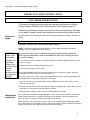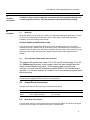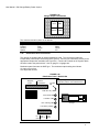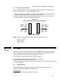
1
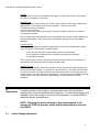
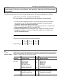
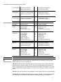
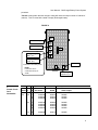
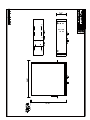
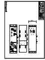
CM Series &
70 Series Battery Power Systems
FILTERED BATTERY CHARGER
OPERATION & MAINTENANCE
GUIDE
SENS part no.:
Document revision:
DCN No.
Date
101051b
A
105073
1/13/2006
Stored Energy Systems
1840 Industrial Circle
Longmont, CO 80501
Fax: (303) 678-7504
Tel: (303) 678-7500
Email: [email protected]
Web: www.sens-usa.com
Installation or service questions? Call SENS at 1-800-742-2326 (303-678-7500) between 8 a.m.
and 5 p.m. (Mountain Time) Monday through Friday, or visit our website.
Copyright © Stored Energy Systems LLC 2006
User Manual - CM Charger/Battery Power System
IMPORTANT SAFETY INSTRUCTIONS
SAVE THESE INSTRUCTIONS
This manual contains important safety and operating instructions for Stored
Energy Systems (SENS) model CM and Battery Power Systems type 70.
Before using the battery charger, read all instructions and cautionary markings
on the battery charger, battery and equipment connected to the battery system.
Before You
Begin
Particular attention should be paid to three types of notices throughout this guide. These are as
follows:
WARNING: is used to warn of possible personal or property injury
CAUTION: is used to warn of possible equipment damage
NOTE: is used in this manual to provide advice on how to obtain maximum performance,
reliability or life from components of your system.
WARNING:
Please read
these safety
warnings and
heed them.
Failure to do
so could result
in either
severe
personal injury
or equipment
damage.
To reduce the risk of injury, charge only properly sized lead-acid batteries.
Other types of batteries or under-sized batteries may burst causing personal
injury and damage.
• Do not install or operate charger if it has been dropped or otherwise damaged. Return it to the
factory for repair.
• Install the charger in accordance with all local codes.
• Do not expose charger to rain or snow.
• Do not disassemble charger; return to factory when service or repair is required. Incorrect
assembly may result in a risk of electric shock or fire.
• To reduce risk of electric shock, de-energize and disconnect the AC input and the battery from
the charger before attempting maintenance or cleaning.
• Use of an accessory not recommended or sold by SENS may result in a risk of fire, electric
shock or personal injury.
• During normal operation, batteries may produce explosive hydrogen gas. Never smoke, use an
open flame, or create sparks near the battery or charger.
• Remove jewelry, watches, rings, etc. before installing battery or charger.
Maintenance
Instructions
User maintenance is limited to charger adjustment. All on-site servicing should be performed by
qualified service personnel. If qualified personnel are not available, return the charger to the
factory for repair, or contact the factory to arrange for field service.
When returning a unit to the factory for repair, ship it in the original factory packaging if possible.
If the original carton is not available, pack in a carton with at least 2 inches of approved packaging
material on all sides of the charger to help prevent shipping damage.
2
User Manual - CM Charger/Battery Power System
1
Installer’s
Instructions
2
Installation
CAUTION: Failure to follow installation instructions may cause equipment damage, and
void the equipment warranty. Read the installation instructions before proceeding.
2.1
Mounting
Mount the charger in a 19” relay rack. Refer to the appended drawings for dimensions. Protect
the unit from construction grit, metal chips, paint or other debris. Clean away debris after
installation and before turning on the charger.
BATTERY POWER SYSTEM INSTALLATION
If your charger was supplied with a battery pack, install the battery pack in the rack before
installing the charger. Remove the top of the battery pack, install the batteries according to the
diagram inside the battery pack, and replace the battery pack top cover. Next install the charger
and connect the charger and battery pack together with the keyed cable supplied with the
charger.
2.2
AC Input Power Requirement and Connection
The charger will operate from either 115 or 230 volt AC mains supply, 50 or 60
Hz. Before applying power to the charger, select the input voltage using the
switch on the charger’s rear panel. The frequency does not need to be
selected. An input cord with standard grounded NEMA 5-15P molded plug is
included. For use with different AC sockets, cut off the standard plug and attach
the correct plug.
WARNING: The battery charger should be connected to a grounded permanent wiring system.
The input cord is equipped with a ground wire for this purpose
2.4
Output Power Connections
Chargers come with one of the two output schemes shown below.
Model suffix
-A410
-A4A0
2.4a
Bulk output
Yes - keyed connector
Yes - keyed connector
Distribution/disconnect panel
None
Yes - 6-circuit
Bulk power connections
The bulk output required a special keyed connector supplied by SENS. The layout of the keyed
connector on the charger, as viewed from the back, is shown below:
3
User Manual - CM Charger/Battery Power System
FIGURE 2.4a
Charger Output Connections
POS
NEG
SPACE
GRND
The connector and wire colors are as follows:
Bulk power output
Connector color
Negative
Black
Positive
Red
Ground
Green
Spacer
Red
2.4b
Battery or output cable wires
Black
White
Green
n/a
Distribution Panel Connections
This charger is equipped with an integral distribution panel. The rear panel includes six
independently-fused output terminals (positive ground). Connect your load lead(s) directly to the
appropriate compression terminals (see Figure 2.4). Connect all hot leads to the negative block;
all return leads to the positive block. Use 12-gauge or 14-gauge wire.
Distribution panel fuses are the GMT type. The maximum output loading is as follows:
• 5 amps any one fuse
• 25 amps total all fuses
FIGURE 2.4b
Distribution Panel - Model A4A0
Negative
output
Positive
connections
Low DC
Adj.
Battery charger rear left panel
Distribution panel w/ volt load disconnect
Load disc. adj.
Fuse blown LED
Output fuses
Load disc. LED
Disc. warning LED
Charger
Low battery voltage
F OK C OK F C
Low
Fuse
not
used batt. V blown
4
User Manual - CM Charger/Battery Power System
2.5
Charger alarm connections
Attach to the charger’s Form C (dry contact) alarm connections located on the charger’s rear
panel, as shown in Figure 2.5. Use the following procedure:
1. Unplug the two plug-in alarm blocks. If no blocks are present, check the packaging material;
the blocks may have been pulled out when the unit was unpacked.
2. Connect your alarm leads to the appropriate terminals in the lug block. Use 18-gauge wire.
3. Re-insert the plug-in alarm block into the distribution panel.
Figure 2.5
Charger Rear Panel Form C Alarm Configuration
CHGR
FAIL
HIGH
DC
OK
OK
FAIL
FAIL
COM
COM
OK
OK
FAIL
FAIL
COM
COM
LOW
CHGR V.
AC
FAIL
CHARGER ALARMS
NOTE: Do not exceed any relay's maximum current rating which is as follows:
0.25 A at 125 VAC
0.5 A at 54 VDC
1.0 A at 28 VDC
3
Operation
3.1
Start-up
After power is applied to the charger, the AC FAIL and CHARGE FAIL lights should extinguish,
and be replaced by the green AC ON light. The charger will automatically supply power to the
load and maintain the battery without further attention from the user.
If the charger does not start up as described, check the following:
a) AC mains power is available, and the AC input fuse has not blown
b) Contractor-installed AC connections are correct
c) If the above steps do not solve the problem, contact SENS at the toll-free number listed on the
front of this manual.
3.2
Alarm Indications
The charger contains a multi-alarm system with front panel status indicators and Form C
contacts. The meaning of each indication is as follows:
AC POWER ON
Indicates that AC power is being supplied to the charger.
5
User Manual - CM Charger/Battery Power System
AC FAIL
Indicates that AC power is not available to the charger. The AC either failed, or the charger’s
input fuse is not installed, or has blown.
CHARGE FAIL
The charger senses voltage rather than current to detect "failure"; once battery voltage drops
approximately 1 volt below nominal the alarm activates. This may occur when:
• The battery becomes discharged
• The AC power has failed
• There is an excessive load on the charger, causing the charger to operate in current limit
• The charger has failed
There is a time delay of approximately one minute between the start of the alarm condition and
the actual alarm signal. This prevents spurious indications during short-term deep battery
discharge.
LOW DC VOLTS
Indicates that DC voltage has dropped to approximately 8.5% below nominal battery voltage
(e.g. 44 volts for a 48 volt system). Probable causes:
a) The AC power has failed, and the battery has become discharged
b) The charger has malfunctioned and the battery has become discharged
c) The battery is defective
There is a time delay in the low voltage alarm which prevents the alarm from activating until
approximately one minute after the low voltage condition starts.
HIGH DC VOLTS
Indicates that the charger’s output has exceeded a pre-set threshold level (approximately 20%
above nominal battery voltage - e.g. 58 volts for a 48 volt system). If this alarm stays activated
for any period of time, the charger should be shut down and serviced. The charger may have
malfunctioned, or the alarm card may be misadjusted. The alarm actives immediately upon high
voltage condition, but stays activated for approximately one minute after the condition
disappears.
4
Adjustments
Customer service of the charger is recommended only if the technician is
experienced in electrical and electronic equipment. If a trained technician is not
available, return the charger to the factory for adjustment, or contact SENS to
make field service arrangements.
NOTE: Changing the factory settings on any potentiometers in the
charger will VOID the warranty unless written authorization is received
from SENS.
4.1
Output Voltage Adjustment
6
User Manual - CM Charger/Battery Power System
WARNING: Working inside the charger exposes you to potentially lethal voltages. Exercise
extreme caution to not touch circuit breakers, filter capacitors, heat sinks or any other exposed
metal surfaces
Conditions under which you should make adjustments to the output voltage are as follows:
a) To correct a previous unauthorized adjustment
b) If your battery is consistently being over-charged or under-charged
1. Use a precision external voltmeter connected directly across the battery
terminals or to the DC plug that supplies the battery. Ensure that the
charger is supplying at least one amp load.
2. Open the charger’s front panel and locate the control card. It contains two
potentiometers labelled “FLOAT” and “BOOST”.
3. Remove the paper dot from the FLOAT pot. Adjust the FLOAT pot until
the desired voltage is achieved. Replace the paper dot. Adjusting the
BOOST pot does nothing.
4.2
Factory-Set Output Voltages
Chargers set for sealed maintenance-free lead-acid battery
Float voltage
5
Troubleshooting Guide
12 volt
24 volt
48 volt
13.56
27.12
54.24
SENS’s policy is to help field technicians correct problems as fast and inexpensively as possible.
Please do not hesitate to call SENS; toll-free number to obtain assistance in troubleshooting our
chargers. Calling us will save you time and trouble.
Symptom
Possible cause
Test
Repair procedure
No output
AC fuse blown
DC fuse blown
No AC power
TB-3 disconnected
Defective control circuit
Defective transformer
#1
#1
Replace fuse
Replace fuse
Restore AC
Reconnect
Call SENS for assistance
Call SENS for assistance
Wrong input voltage
Defective control circuit
#3
AC fuse blows
#2
Connect to correct voltage
Call SENS for assistance
7
User Manual - CM Charger/Battery Power System
DC fuse blows
Defective control circuit
Battery leads reversed
Call SENS for assistance
Reconnect DC leads
Overcharging
Improper o/p voltage setting
Defective control circuit
#4
Adjust output voltage
Call SENS for assistance
Undercharging
Improper o/p voltage setting
Defective control circuit
#4
Adjust output voltage
Call SENS for assistance
Indication
Possible cause
Test
Repair procedure
AC fail
AC fuse blown
No AC power
Defective alarm circuit
#1
Replace AC fuse
Restore AC
Call SENS for assistance
Charge fail
AC fuse blown
DC fuse blown
No AC power
Excessive load
Battery voltage low
Defective alarm circuit
#1
#1
Replace AC fuse
Replace DC fuse
Restore AC
Reduce load
Dead battery
Call SENS for assistance
High DC
Improper boost/float settings
Defective control circuit
Defective alarm circuit
#4
Adjust output voltages
Call SENS for assistance
Call SENS for assistance
Low DC
AC fuse blown
DC fuse blown
No AC power
Excessive load
Defective alarm circuit
#1
#1
Replace AC fuse
Replace DC fuse
Restore AC
Reduce load
Call SENS for assistance
Alarm Indications
6
Test Procedures
#5
#5
Test #1: Remove the fuse and measure its resistance using an ohmmeter on the Rx1 range.
Meter should read 0 ohms for a good fuse.
Test #2: Energize the charger after disconnecting the secondary leads from the control board
and measure the secondary voltage. Do not short circuit the leads while performing this test.
The AC voltage should be 1.5 to 2 times the nominal output voltage of the charger. The control
winding (TB-3) should be approximately 10-14 volts AC rms. See Figure 6 below for location of
leads.
Test #3: Check the information on the nameplate to insure it agrees with the AC voltage applied.
Test #4: Measure the battery voltage using a 1% accuracy voltmeter. If the charger's voltage is
not set properly for your batteries, adjust float/boost settings according to the adjustment
8
User Manual - CM Charger/Battery Power System
procedure.
Test #5: Loads greater than the charger's rating will cause the output current to "fold back"
(reduce). This is normal with a dead or deeply discharged battery.
FIGURE 6
TB-1
Brown wire (-) DC
Red wire (+) DC
TB-3
Orange striped
wire (AC)
Solid orange
wire (AC)
Not used
Transformer secondary leads
NOTE:
Leads must be reconnected exactly as
shown
7
Printed Circuit
Card
Assemblies
Float voltage
adjustment pot
Alarm
board
Remote
alarm output
205849K
205850K
205860K
203340
203340
203340
203962
203962
203962
6
8
12
15
205879K
205880K
205852K
205861K
203320
203320
203320
203320
203962
203962
203962
203962
12
205856K
203310
203962
Model
V
A
CM
48
8
12
15
24
12
Main
pwr board
9
User Manual - CM Charger/Battery Power System
8
Product
Description,
Features
Stored Energy Systems’ CM chargers are fully automatic battery chargers and DC current
sources which offer the following features:
• Constant voltage output
• Electronic current limiting
• Filtered output to meet common telecommunications standards
• Battery charger or battery eliminator operation
The chargers are designed for use with telecommunications or other equipment requiring a low
ripple DC source. The battery charger automatically recharges and maintains maintenance-free
lead-acid batteries.
1.2
Specifications
Input voltage and frequency
115/230 volts +10%; 47-63 Hz
Output voltage
• 48, 24 or 12 volts nominal, single rate charging
NOTE: Output voltage is factory set for maintenance-free batteries unless otherwise specified
• Float voltage adjustable from approximately 90% to 120% of nominal.
Power conditioning
Power conditioning input transformer and varistors; plus single or two-stage inductor system for
additional protection
Voltage regulation
Better than 1% from no load to full load with simultaneous variations in input voltage of 10% and
frequency of 5%
Current limiting & overload protection
Inherent current limiting at 100% to 110% of rated output
Ripple & noise
30 mV maximum ripple when connected to a battery having capacity in AH four times the ampere
output rating of the charger. 50 mV rms maximum (25 mV typical) with battery disconnected
Parallel operation
Chargers can be operated in parallel for redundancy. Chargers may share the load depending
on how close the voltage settings are.
Protection
Current limited output; sustains short circuit
Standard AC and DC circuit fuses
Output blocking diode
Indicators
• Front panel:
Charge fail
AC fail
Power on
High battery voltage
Low battery voltage
LED
LED
LED
LED
LED
10
User Manual - CM Charger/Battery Power System
• Alarms
Charger fail
AC fail
High battery voltage
Low battery voltage
Form C (dry contact) relay
Form C (dry contact) relay
Form C (dry contact) relay
Form C (dry contact) relay
Delay circuitry in the low and high battery alarm systems prevents spurious indications
Controls & adjustments
• Float voltage adjustment
• Separate adjustments for low and high charger voltage alarms
Ambient
Operates without de-rating from -10C to +50C. Humidity 5% to 95%, non-condensing. Natural
convection cooled.
11