1
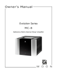
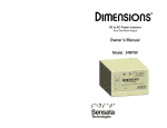
®
DC to AC Power Inverter/Charger
Pure Sine Wave Output
Owner’s Manual
Models:
12NP10
12NP12
12NP15
12NP18
12NP20
12NP24
Model:
12NP30
INTRODUCTION
Thank you for purchasing a Dimensions Inverter from Sensata Technologies!
We think that you will find this product to be extremely reliable and easy to use.
We have put a lot of time and effort into this system to make it a product that you
will be completely satisfied with.
Please read this manual completely, before installation and operation.
Contact us by phone or email if you need assistance with this product.
We can be reached at:
1-800-553-6418
http://dimensions.sensata.com
[email protected]
SAFETY INSTRUCTIONS
IMPORTANT
Read this manual before installation, it contains important safety, installation and
operating instructions. Save this manual and keep it in a safe place.
Sensata Technologies is an ISO 9001:2008 Registered Company.
Sensata uses the following special notices to help prevent injury and/or damage to
equipment.
DANGER indicates an imminently hazardous situation which, if not
avoided, will result in death or serious injury.
WARNING indicates a potentially hazardous situation which, if not
avoided, could result in death or serious injury.
CAUTION indicates a potentially hazardous situation which, if not
avoided, may result in minor or moderate injury.
CAUTION used without the safety alert symbol indicates a potentially hazardous
situation which, if not avoided, may result in property damage.
NOTE is used to notify of installation, operation, or maintenance information that
is important but not hazard related.
SAFETY LISTING
Power Inverter, E100666
2
Inverter Safety Instructions
WARNING: Power Inverters produce hazardous voltages. To avoid risk of
harm or fire, the unit must be properly installed.
WARNING: There are no user serviceable parts inside, do not remove the
cover.
WARNING: Power Inverters should not be mounted in a location that may
be exposed to rain or spray.
WARNING: Power Inverters should not be installed in a zero clearance
enclosure.
WARNING: Damage to the Power Inverter will occur if correct polarity is
not observed when installing the inverter’s DC input cables.
WARNING: Damage to the Power Inverter will occur if an external AC
power source is applied to the inverter’s AC hardwire output.
WARNING: Power Inverters contain a circuit breaker and capacitor that may
produce a spark upon connection or during normal operation. Do not mount in a
confined battery or gas compartment.
WARNING: Be sure the Power Inverter is turned OFF during installation.
WARNING: Be sure the Power Inverter is turned OFF and AC power is
disconnected when batteries are being connected, disconnected, serviced, and
replaced or personal injury and/or damage to the inverter could result.
Battery Safety Instructions
WARNING: Working in the vicinity of lead-acid batteries is dangerous.
There is a risk of acid exposure.
WARNING: Batteries generate explosive gases during operation.
WARNING: There is risk of high current discharge from shorting a battery
that can cause fire and explosion. Use insulated tools during installation.
WARNING: Remove all rings, watches, jewelry or other conductive items
before working near the batteries.
WARNING: Inspect the batteries at least once a year for cracks, leaks or
swelling.
WARNING: Dispose of the batteries according to local regulations. Do not
incinerate batteries; risk of explosion exists.
WARNING: Be sure the Power Inverter is turned OFF and AC power is
disconnected when batteries are being connected, disconnected, serviced, and
replaced or personal injury and/or damage to the inverter could result.
3
TABLE OF CONTENTS
INTRODUCTION ..................................................................................................................2
SAFETY INSTRUCTIONS .................................................................................................... 2
Inverter Safety Instructions .............................................................................. 3
Battery Safety Instructions ............................................................................... 3
SPECIFICATIONS ................................................................................................................5
OTHER DESIGN FEATURES ............................................................................................... 5
PHYSICAL DESCRIPTION .............................................................................................. 6-7
MOUNTING THE INVERTER .............................................................................................. 8
Installation Tools ................................................................................................ 8
Inverter Mounting Recommendations ............................................................ 8
DC WIRING GAUGE & FUSING ....................................................................................... 10
Inverter Cable.................................................................................................... 10
Cable Recommendations ................................................................................ 10
TEMP COMP CABLE CONNECTION .............................................................................. 10
AC INPUT& OUTPUT CONNECTIONS ........................................................................... 11
REMOTE STATUS PANEL & REMOTE INV. ON/OFF SWITCH ................................... 12
WIRING DIAGRAM ........................................................................................................... 13
Typical DC Wiring Diagram............................................................................. 13
OPERATION (Using LED Display Panel) ........................................................................ 14
Inverter Power Mode (Using LED Display Panel) ....................................... 14
External Power Mode (Using LED Display Panel) ....................................... 16
OPERATION (Using Remote ON/OFF tab) ..................................................................... 18
Inverter Power Mode (Using Remote ON/OFF tab)..................................... 18
External Power Mode (Using Remote ON/OFF tab) .................................... 18
THEORY OF OPERATION .................................................................................................. 19
Inverter Power Mode....................................................................................... 19
External Power Mode ...................................................................................... 19
Bypass Relay..................................................................................... 19
Battery Charger ................................................................................ 20
TROUBLESHOOTING GUIDE ........................................................................................... 22
LED Display Panel Messages ......................................................................... 22
LED Status Chart .............................................................................................. 24
Troubleshooting ................................................................................................ 25
APPENDIX .......................................................................................................................... 26
Ignition Switch Control with the LED Display Panel ................................... 26
3 Step Battery Charger Recipes with Temp. Comp. Cable ........................ 27
Accessories & Replacement Parts ............................................................... 28
Inverter Charger Model Options .................................................................... 29
LED Display Panel Mounting .......................................................................... 29
LIMITED WARRANTY TERMS & CONDITIONS ........................................................... 30
4
SPECIFICATIONS
MODEL NUMBER
INVERTER 12NP10 12NP12 12NP15 12NP18 12NP20 12NP24 12NP30
Output Power
1000
1200
1500
1800
2000
2400
3000
(Watts Cont.)
Output
Current (Amps
8.3
10
12.5
15
16.7
20
25
AC Cont.)
Input Current
(Amps DC Up to 106 Up to 129 Up to 167 Up to 188 Up to 214 Up to 255 Up to 315
Cont.)
Peak Power
2000
2500
4500
5500
(Watts)
Peak Output
35
37
40
58
68
74
80
(Amps AC)
Motor Starting
1/3
1/2
1/2
3/4
1
1
1
Rating (hp)
Weight (lbs.)
40
40
40
40
40
40
68
Dimensions in. 12 x 14.5 12 x 14.5 13.4 x 12 x 14.5 12 x 14.5 13.4 x
14.8 x
(L x W x H)
x 5.7
x 5.7 14.5 x 5.7 x 5.7
x 5.7 14.5 x 5.7 17.1 x 8
Output
120 +/- 3%
Voltage (VAC)
Output
60 +/- .05%
Frequency:
Output
Pure Sine < 5% THD
Waveform:
Input Voltage:
10.5-17.0
(VDC)
Operating
-20C to 65C (0F to 149F)
Temperature:
Efficiency:
Up to 88%
BATTERY
CHARGER
AC Input
Voltage Range
95-135
(VAC)
Input Current
Up to
Up to
Up to 9 Up to 8.7 Up to 13
Up to 17
Up to 22
(Amps AC)
13.5
18.7
Output (Amps
Up to 60 Up to 65 Up to 75 Up to 95 Up to 115 Up to 130 Up to 150
DC)
BYPASS*
(Amps AC)
20
20
20
20
*Note – Bypass relay is rated at 30 amps for all models.
5
30
30
30
OTHER DESIGN FEATURES
Other Design Features: thermally controlled cooling fan, GFCI outlet protection,
and Remote LED Display Panel or “On/Off” switch hookup.
Unit Protection: Automatic electronic short circuit/overload protection,
Automatic over temperature shutdown, and AC output circuit breaker(s).
Battery Protection: Automatic low battery shutdown at 10.5VDC with in-rush
delay.
Temperature Compensated Charging: Allows for proper temperature charging
across the operating range of the inverter.
Auto Sleep Mode: When the LED Display Panel is used, the inverter can be
programmed to go to sleep after no load is detected over programmed interval.
Optional LCD Remote: For an additional cost, we have an LCD remote available
PHYSICAL DESCRIPTION
1
(1)
(2)
(3)
(4)
(5)
(6)
(7)
2 3
4
8
5 6 7
DC input connections: Connects to the battery bank.
Bonding lug: Connects to the ground system.
AC Input & Output (hardwired): Terminal blocks are provided behind
front access cover for hardwiring AC Input and Output.
Temp. Sense Connector Port: Connects to the temp. comp. cable
Output Breaker, Branch Breaker: Trips to protect the inverter’s internal
circuitry from shorted AC loads or overload situations.
AC Wiring Plate: Remove this plate to access the AC wiring terminal block
or to replace a GFCI outlet.
GFCI: Provides 120VAC output. Only replace with same model GFCI.
6
(8)
Display, Inverter On/Off, Remote: The display will give you current
status information as well as allow you to turn the inverter On and Off.
This panel can be used as a remote with the remote kit.
1
4
3 2 6 7
5
8
9
10
(9)
11
Battery Type Selector Switch: Slide this switch to match the type of
batteries that you are using for battery proper charging.
(10) Status LED: This LED will show the operation mode of the inverter and
charger. The LED also shows troubleshooting information. See the table in
the troubleshooting section at the rear of the manual for further operation
mode descriptions.
(11) Remote ON/OFF Tab: Use this tab if you wish to wire an inverter remote
control switch. NOTE – The LCD Panel can also be relocated as a remote.
Order remote LCD panel kit# 625000.
7
MOUNTING THE INVERTER
Installation Tools
The following tools are required for inverter installation: Crimper, Cable Ties,
Cutter, Drill, #2 Phillips Screw Driver, Slotted Screw Driver, Tape Measure, Wire
Cutters, and Wire Strippers.
Inverter Mounting Recommendations
NOTE: The inverter mounting location should provide adequate ventilation and
clearance to maintain room temperature during operation. At least ½” of clearance
is required on all sides.
1. Locate a suitable, secure, horizontal mounting surface as close to the batteries
as possible without being in the same airtight compartment.
2. Mount the inverter using four, ¼-20 steel bolts, flat and lock washers, and
nuts. The length of the bolts should be equal to the mounting material
thickness plus ¾”.
Mounting for Models: 12NP10, 12NP12, 12NP15, 12NP18, 12NP20,
12NP24 (units are in inches)
8
Mounting for Model: 12NP30 (units are in inches)
9
DC WIRE GAUGE & FUSING
Inverter Cable
An “Inverter Cable Kit” (positive cable, negative cable, and proper fuse) is needed
to connect the inverter to a battery bank. An 8-guage single strand cable is also
recommended to connect the inverter’s bonding lug to ground.
The inverter cable length and the size of the inverter will determine the cable gauge
and the fuse size to use. The maximum inverter cable recommended is 20-ft; it
must be fused within 18-in from the positive (+) terminal of the battery.
Cross reference the inverter model, and the estimated cable length in the table
below to determine the proper cable gauge and fuse size. An inverter cable kit
designed to SAE guidelines can be purchased directly from our factory – call for
options.
Minimum Cable and Fusing Guide at 5% Voltage Drop at Full Output Inverter to Battery Estimated Cable Length in Feet Inverter Full Load 1 to 10 feet
11 to 15 feet
16 to 20 feet
Model (Amps DC) 12NP10 104 4-ga, 200A Fuse 2-ga, 250A Fuse
1-ga, 300A Fuse
12NP12 129 2-ga, 250A Fuse
2-ga, 250A Fuse
1/0, 350A Fuse
12NP15 156 2-ga, 250A Fuse
1-ga, 300A Fuse
2/0, 400A Fuse
12NP18 188 2-ga, 250A Fuse
1/0, 350A Fuse
2/0, 400A Fuse
12NP20 204 1-ga, 300A Fuse
2/0, 400A Fuse
3/0, 500A Fuse
12NP24 255 1/0, 350A Fuse
2/0, 400A Fuse
4/0, 600A Fuse
Not Recommended
12NP30 315 2/0, 500A Fuse
3/0, 500A Fuse
NOTE:
• Temp. Comp. cable is part# 611622-XX (XX=length in feet - 9, 15, 20,
25, 30)
Cable Recommendations
To make your own “Inverter Cable Kit,” follow below recommendations:
1. Use stranded copper cables in all cases.
2. USE SGX cross-linked polyurethane insulation type that complies with the
high temperature insulation requirements (125°C.) of SAE J-1127 and vehicle
manufacturer requirements.
10
TEMP COMP CABLE CONNECTION
Connect the lug end of the temperature compensation cable to the negative post of
the most negative point in the battery bank. Connect the two pin connector to the
appropriate mating connector located at the side of the inverter labeled “Temp.
Sense.” Use the slide switch on the right side of the inverter and select the battery
type that you are using for proper battery charging.
NOTE: If the temp. Comp. Cable or Dongle is not connected; the battery charger
will not function
AC INPUT & OUTPUT CONNECTIONS
WARNING: Do not connect another source of
AC power directly to the output of the inverter. This
will result in damage not covered under warranty.
Tighten to 14.6 in/Lbs
The inverter’s 120 VAC output power is provided at
the GFCI receptacle and the hard wire terminal
blocks behind the access panel.
Wire the AC Input to the hard wire terminal blocks
behind the access panel for charging and shore power.
NOTE: Remove the black hole covers as needed for
hardwire AC wiring. Use a romex type clamp to
protect the wires from the metal edge of the hole.
Apply 14.6 in/Lbs torque to the terminal block
screws.
NOTE: Systems rated at 2500 watts and above should be powered with a 30A
circuit.
NOTE: Connecting the plug-in cord to GFCI protected outlets may cause some
interference with the inverter’s GFCI.
NOTE: For GFCI protected hardwire output. Wire directly to the GFCI “Load”
terminals. Verify that you are connecting to the un-used “Load” terminals.
11
REMOTE STATUS PANEL & REMOTE INV. ON/OFF SWITCH
Remote Status Panel
The display panel can be removed from the inverter and installed in a different
location in the vehicle for remote control and monitoring. Please follow the
following procedure closely.
Unscrew the two screws that hold the panel in using a 3/32” allen wrench.
Disconnect the RJ45 connector from the back of the remote panel and re-connect
it to the backside of the replacement RJ45 cover plate.
WARNING: Mount the RJ45 cover plate on the inverter with the two screws
provided in the remote extension kit (8-32x3/8”). DO NOT USE the screws that
held the display to mount the RJ45 cover plate. Using any other screw type or
length than that provided in the kit may damage the inverter and/or harm the
installer. Tighten the screws to 16-17 in/Lbs.
Connect the extension cable to the RJ45 jack and route through the vehicle to the
desired location. See the appendix for mounting hole size and placement
information. Install the remote display panel at the desired new interior location
using installer supplied #8 screws and connect the extension cable to it.
Remote Inverter ON/OFF Switch
An optional customer supplied remote switch can also be used to control the
inverter. Mount the remote switch in a convenient location. Using 18awg wire
and an insulated female faston, wire between the “Remote ON/OFF” connection
on the right side of the inverter and the remote switch. Wire from the remaining
connection on the remote switch to the battery. Make sure to have a 5-amp in-line
fuse installed in series within 10 inches from the positive (+) terminal of the battery.
12
WIRING DIAGRAM
Typical DC Wiring Diagram
13
OPERATION (Using LED Display Panel)
Once the inverter has been fully installed and wired, and DC power has been
applied, the 7 segment display panel will come to life. This display panel shows the
status and configuration information of the inverter and charger. You can also turn
the inverter on and off by pressing the [ON/OFF] key and also make configuration
changes using the [MENU] and [DISPLAY/SELECT] keys.
NOTE: This LED Display Panel
can be removed from the front of
the inverter and mounted in a
convenient and dry location
(e.g.; in the cab of the vehicle).
Order remote extension kit
#625000
NOTE: The inverter can also be
controlled by the ignition of the
vehicle, see Appendix for
detailed information on this
feature.
The first message that you will see scroll on the 7 Segment Display once DC power
is applied is:
chgr
Inv
Off
chec
ac
This message is “charger inverter off check AC,” which simply means that both the
charger and inverter are off and that the unit is not plugged into shore power or
there is a problem with AC power coming to the unit.
Inverter Power Mode (Using LED Display Panel)
1) Turning the Inverter “ON” or “OFF” (no AC applied):
Simply press the [ON/OFF] key and the inverter will turn on. The
“ON/STBY” LED will also come on green. Press the [ON/OFF] key again to
turn the inverter off.
While the inverter is on the following message will display:
Inv
550
watt
12.6v
This message shows that the inverter is on, the load is consuming 550 watts of
power, and that the battery voltage is currently at 12.6 volts.
14
2) Inverter “Stby”
The inverter standby feature allows the inverter to automatically come on
anytime that it senses a loss of shore power and then go back to standby when
shore power is returned (after 22 seconds of line qualify time).
This feature is enabled by turning the inverter on by pressing the [ON/OFF]
key. If this is done while shore power is applied the “ON/STBY” LED will
come on Amber and the display will show:
Inv
stby
push
Off
This message is stating that the inverter is in standby and that to exit this mode
you need to press the [ON/OFF] key.
NOTE - To exit Inverter standby mode, press the [ON/OFF] key.
If you turn off the inverter while shore power is applied the display will show:
Inv
Off
push
stby
This message is stating that the inverter is off and that to put it back to standby
you need to push the [ON/OFF] (Stby) key.
3) Other inverter messages:
Inv
LOW
batt
9.8v
Low battery condition due to start surge or undersized battery cable gauge. If
this condition remains for => 5seconds the inverter will shutdown.
Inv
OvL
batt
11.8v
Overload condition due to excessive loads or short circuit. If this condition
remains for => 5seconds the inverter will shutdown.
4) Battery Test
The battery voltage can be tested at anytime by pressing the [BATT TEST]
key. The mode will stay active for 1 minute or until the [BATT TEST] or
[MENU] key is pressed.
12.6v
5) Battery Trough (low battery voltage point)
If while using the inverter, the inverter temporarily shuts down due to a low
DC input condition, you can check to see how low the DC input voltage
momentarily went to. To see this value, press the [BATT TEST] key. Then
15
press the [DISPLAY/SELECT] key. The display will show “LO BATT”
followed by the recorded minimum low input condition (trough) voltage. The
mode will stay active for 1 minute or until the [BATT TEST] or [MENU] key
is pressed. The following message shows the low point at 10.1 volts.
Lo
batt
10.1v
If there is not a value stored, the message will just say “Lo batt ---” and not list
any voltage.
You can clear the stored value manually by pressing the [DISPLAY/SELECT]
key while the message is scrolling. You will then see the following flash twice:
cLr
batt
A newly recorded value will also clear the old value and replace it with the new.
6) Auto Sleep Mode
This feature is used to turn the inverter off if there has been zero watts drawn
for the set amount of time. For example if the sleep mode is set to 30 minutes
and 30 minutes of time has elapsed with no power being drawn from the
inverter, the inverter will shut off. The inverter must then be manually turned
back on again when needed. You can adjust this setting by pressing the
[MENU] key twice. You will then see:
Avto
SLEp
OFF
To change the setting press [DISPLAY/SELECT] repeatedly until the desired
setting appears. The options are OFF, 30M, and 15M. The default setting is
Off.
External Power Mode (Using LED Display Panel)
1) Bypass Relay: The loads attached to the inverter output will operate directly
from the external AC power line independently of the inverter ON/OFF
status. If the inverter is left ON (standby mode), the built-in bypass relay will
automatically cycle back and forth between “Inverter Power” mode and
“External Power” mode depending on the availability of the external AC power
line.
BATTERY CHARGER
The battery charger will engage automatically and independently of the inverter
ON/OFF status. The 3-step charging process modes are; Bulk, Acceptance, and
Float.
16
2) AC Input Limit (Charger AC current limit)
The maximum AC current that the charger will be allowed to draw is
adjustable. This value can be set to 30-0A (maximum value is factory set based
on model). The default setting is for 15 amps. Press [MENU] to display the
current setting. The message will then scroll:
AC
In
Lmt
15A
To change the value press [DISPLAY/SELECT] and the value will decrease in
5A increments. The charger stores the last value shown on the display.
3) Charger Modes
The charger has three modes of operation; Bulk, Accept, and Float. The
display panel will state which mode the charger is in when shore power is
applied. The mode along with the charge voltage and current will be
displayed.
Bulk Mode:
chgr
bulk
12.3v
50a
acpt
14.4v
15a
FLOt
13.1v
0a
Accept Mode:
chgr
Float Mode:
chgr
4) Temperature Compensation Cable or Dongle
If the temperature compensation Cable or Dongle is not connected to the
“Temp. Sense” connector on the inverter; the battery charger will not
function, the red “FAULT” LED will come on, and the display will show:
chgr
OFF
batt
prOb
Check to make sure that the cable is connected.
17
OPERATION (Using Remote ON/OFF tab)
Once the inverter and remote On/Off switch have been fully installed and wired,
and DC power has been applied, the inverter is ready to turn on. The Status LED
on the right side of the inverter shows the status information of the inverter and
charger.
Inverter Power Mode (Using Remote ON/OFF tab)
1) Turning the Inverter “ON” or “OFF” (no AC applied):
The inverter can now be turned on by turning on the remote switch. When
the inverter is on the Status LED will blink Amber.
External Power Mode (Using Remote ON/OFF tab)
1) Bypass Relay: The loads attached to the inverter output will operate directly
from the external AC power line independently of the inverter ON/OFF
status. If the inverter is left ON (standby mode), the built-in bypass relay will
automatically cycle back and forth between “Inverter Power” mode and
“External Power” mode depending on the availability of the external AC power
line.
BATTERY CHARGER
The battery charger will engage automatically and independently of the inverter
ON/OFF status. The 3-step charging process modes are; Bulk, Acceptance, and
Float.
2) Battery Charging Modes
The charger has three modes of operation; Bulk, Accept, and Float. The
Status LED will state which mode the charger is in when shore power is
applied.
Charging Status LED Normal States
LED State
Operating Conditions
LED Color
Bulk Charge
1 blink
Green
Accept Charge
2 blinks
Green
3 blinks
Float Charge
Green
4 blinks
Load Management Active
Green
3) Temperature Compensation Cable or Dongle
If the temperature compensation Cable or Dongle is not connected to the
“Temp. Sense” connector on the inverter; the battery charger will not function
and the Status LED will blink Red 5 times.
18
THEORY OF OPERATION
Inverter Power Mode
Usage: Any 120 VAC, 60 Hz single phase product within the inverter’s power
rating.
The Display Panel [ON/OFF] key or a voltage between 8 and 20 volts applied to
the “Remote On/Off” input controls the inverter.
Operational modes: “External Power” mode and “Inverter Power” mode.
The LED Display Panel “ON/STBY” LED will be on Green and the Status LED
will blink Amber while the inverter is on. The AC power produced by the inverter
comes from the energy stored in the battery bank through a sophisticated electronic
inversion process. A transformer, a Metal Oxide Silicon Field Effect Transistors
(MOSFET), a filter capacitor and microprocessor control are used to generate clean
AC power.
The inverter will operate at DC input voltages ranging from 10.5 to 17 volts.
Above 17 volts the system will stop operating due to input voltage being out of
range. The inverter can tolerate up to 17V DC input. When the input voltage
drops to 10.5 volts, the inverter will stop operating due to a low battery condition.
When the lead acid battery bank voltage drops to 10.5 volts, the battery is fully
discharged.
Note: The signal output waveform produced by the inverter when in “inverter
mode” is pure sinusoidal. It has a total harmonic distortion of less than 5%.
External Power Mode
The LED Display Panel will show charger mode and output and the Status LED
will blink Green indicating that there is a valid external AC power line applied to
the inverter AC input.
Bypass Relay: The loads attached to the inverter output will operate directly from
the external AC power line independently of the inverter ON/OFF status. If the
inverter is left ON (standby mode), the built-in bypass relay will automatically cycle
back and forth between “Inverter Power” mode and “External Power” mode
depending on the availability of the external AC power line.
19
Battery Charger: The battery charger will engage automatically and independently
of the inverter ON/OFF status. The 3-step charging process modes are; Bulk,
Acceptance, and Float.
The LED Display Panel will show charger mode and the Status LED located on the
side of the inverter will blink Green to indicate the charging process mode (1 blink
= Bulk, 2 blinks = Accept, 3 blinks = Float).
NOTE: The charger is capable of charging AGM, GEL, or Wet cell batteries.
Select battery type by using the slide switch on the right side of the inverter.
Charger operation with temperature compensation cable:
The battery charger temperature compensation cable measures the battery
temperature and automatically adjusts the charger output voltage for the fastest and
safest charge.
When batteries are cold, their chemical reaction is slowed, so they will not take on a
charge as easily. A charge voltage optimized for room temperature will not charge
the battery at low temperatures. The temp comp cable allows the charger to
increase the charge voltage for optimum charging at low temperatures.
When batteries are hot, their chemical reaction is accelerated and they absorb
energy too readily. A charge voltage optimized for room temperature will tend to
overcharge the batteries and cause gassing. The temp comp cable will cause the
charger to decrease the charge voltage to a safe level.
Our charger will switch to a “warm battery” mode in which the charger will only
provide a float voltage when the batteries reach 122F/50C -140F/60. If the battery
temperature continues to rise over 140F/60C the charger will shut off. The charger
will resume charging in the “warm battery” mode when the battery cools to
131F/55C. Further, the charger will resume normal charge modes when the
battery cools to 113F/45C.
20
Charger operation with temp comp bypass dongle:
Proper battery charging is best achieved by the use of the temperature
compensation cable. If this is not feasible then the temperature compensation
dongle can be used.
If the charger is used with the Temp Comp Cable Bypass Dongle, the charger will
lock in to a hot setting for the charge voltages per the table. The bypass dongle
may significantly reduce charger effectiveness at low temperatures and will not sense
an overheated battery, and may not avoid a hazardous condition.
3 step Battery Charger Recipes, voltages with Temp Comp Bypass Dongle
Battery type
AGM
GEL
Wet
Acceptance charge voltage (VDC)
13.9
13.3
14.2
Float voltage (VDC)
13.0
13.0
12.7
Load Management:
Incoming AC power is shared between the AC loads and the charger. The AC
loads are given priority; this means the charger will reduce its output with large AC
loads. This feature controls the total amperage draw of the system so the utility
service circuit breaker is not tripped. The Load Management feature will return the
charger to full output when the AC loads are removed or reduced.
Dead battery charging:
The charger will operate anytime the AC line is within the valid range. There is no
minimum battery voltage required for the charger to start.
21
TROUBLESHOOTING GUIDE
Look at the “LED DISPLAY PANEL MESSAGES” and “LED STATUS CHART” below
for LED descriptions. See also the troubleshooting section for more troubleshooting
information.
WARNING: Do not remove chassis cover. No user-serviceable parts
inside.
Call or e-mail customer service for free consultation during business hours (7:30am-5:30pm
central time) at 1-800-553-6418 or 1-651-653-7000; fax 1-888-439-3565 or 1-651-6537600
E-mail: [email protected]; http://dimensions.sensata.com
LED Display Panel Messages
1) Inverter Off Low Battery
Inv
OFF
LOW
batt
The inverter is off due to a low battery voltage condition (<=10.5 volts for 5
seconds). Both the Amber “ON/STBY” and Red “FAULT” LED’s are on.
Check battery charge and DC wiring cable size.
2) Inverter Off Overload
Inv
OFF
OL
The inverter is off due to an overload condition. The Red “FAULT” LED is
on. Remove one or more loads from the output of the inverter. Reset the
inverter.
3) Inverter Off High Temperature
Inv
OFF
high
temp
The inverter is off due to a high temperature condition (>60°C/140°F). Both
the Amber “ON/STBY” and Red “FAULT” LED’s are on. The inverter will
turn back on when the temperature is < 45°C/113°F.
4) Inverter Off High Battery
Inv
OFF
high
batt
The inverter is off due to a high charging voltage condition (>16.9 volts) and
the display reports the value. Both the Amber “ON/STBY” and Red
“FAULT” LED’s are on. Inverter restarts at 15.5 volts. Check the vehicle
alternator/regulator.
22
5) Charger Off High Temperature
chgr
OFF
high
temp
The charger is off due to a high temperature condition (>60°C/140°F). The
Red “FAULT” LED is on. The charger will turn back on automatically when
the temperature is < 45°C/113°F.
6) Charger Off Battery Temperature
chgr
OFF
batt
temp
The charger is off due to a high battery temperature (>47°C/117°F50°C/122°F). The Red “FAULT” LED is on. Check the battery
compartment for proper ventilation.
7) Charger Off Battery Probe
chgr
OFF
batt
prOb
The charger is off due to a shorted or open (missing) temperature
compensations sensor. The Red “FAULT” LED is on. Check the connections.
8) Charger Off High Battery
chgr
OFF
high
batt
The charger is operating in a high DC output voltage condition. The Red
“FAULT” LED is on. Disconnect other battery charger or source and reset.
9) Charger Warm Battery
chgr
warm
batt
The charger reduced output due to warm battery temperature. The Red
“FAULT” LED is on. Check battery compartment for proper ventilation.
23
LED Status Chart
LED Color
Green
Green
Green
Green
Amber
None
Any
Red
Red
Red
Status LED Normal States
LED State
Operating Conditions
Bulk Charge
1 blink
Accept Charge
2 blinks
3 blinks
Float Charge
4 blinks
Load Management Active
Inverting
1 blink
Status LED Fault States
Off
No power to unit or internal fault
Constant ON
Internal fault
1 blink
Inverter Low Battery shut down*
2 blinks
Inverter Overload shut down
3 blinks
Transformer High Temp*
Red
4 blinks
MOSFET High Temp*
Red
5 blinks
Battery probe open or shorted
Red
6 blinks
Charger high battery temp*
Amber
2 blinks
Charger warm battery*
Amber
3 blinks
High battery voltage*
Amber
4 blinks
System overload, reset required
Faults marked with* will self recover when the condition returns to normal
range
24
Troubleshooting
4) No AC output power during inverter mode:
No LED’s On:
• Check the in-line fuse which is located within 18” from the battery’s
positive post.
• DC connections tight and clean?
• Battery voltage to be above 10.5VDC?
• Check Remote Power Switch.
LED blinks Amber once: Disconnect all loads and connect a test light to the
GFCI outlet.
• Check the GFCI to see if it is tripped (Cooper brand GFCI has the LED
go on when tripped, other brands are dark)
• If test light is off: Possible failed inverter
LED blinks Green: Repeat above test
LED blinks Red: See “Led Status Chart”
5) Low Battery: The use of a battery isolator is not recommended due to
excessive voltage drop across terminals.
• Battery voltage must be above 10.5 VDC for the inverter to be on.
• Check for proper DC wire gauge (see Wire Gauge & Fusing section)
6) Overload: Unplug all loads and reset the inverter On/Off.
• Overload condition clears, check for short circuits or check load size
versus inverter output wattage size.
• If the overload persists, possible failed inverter
7) High Temp.: Let the inverter cool down
8) Check Battery: Reset the inverter (unplug/plug AC Input cord from the
utility power) and remove the fuse from the fuse holder. Turn “on” the
inverter for 30 seconds. Turn “off” the inverter. Re-install the fuse.
• Possible battery cell shorted or corroded/loose DC wires
• Check voltage and current against charger recipe table
25
APPENDIX
Ignition Switch Control with the LED Display Panel
The LED Display Panel can be wired to the vehicle ignition circuitry to control
operation of the inverter. When the ignition is turned on, the inverter has a builtin delay which will turn it on after 10 seconds. In order for the inverter to work in
this way the LED Display Panel must be programmed for this type of operation.
This is done by having either AC or DC power applied to the inverter and then
following these instructions:
Ignition Programming:
1. Press and hold [MENU] &
[DISPLAY/SELECT] for 5 seconds. A
Green “FAULT” LED comes on.
2. Press [MENU] once. Display scrolls:
CtL
tab
Off
3. Press [DISPLAY/SELECT]. Display stops
at:
OFF
4. Press [DISPLAY/SELECT] and the display changes to:
Ign
The “ON/STBY” LED will also blink Amber (if unit is connected to AC
power).
5. Press the [BATT TEST] key. Disconnect power to the system and complete
wiring as stated below.
The next step is to use an insulated female faston and using 18awg wire, connect to
the faston tab on the backside of the LED Display Panel. Wire the other end
through a 5 amp inline fuse to the ignition circuitry of the vehicle.
NOTE: It is advisable when using this feature to also take advantage of the Auto
Sleep option of the inverter. See page 13, item 5. If this option is used and the
inverter has gone to sleep, press [ON/OFF] to turn the inverter back on.
NOTE: Repeat steps 1-5 to turn this feature off again.
26
3 Step Battery Charger Recipes with Temp. Comp. Cable
Battery type
AGM
Bulk charge phase
Bulk
Bulk charge current limit
Bulk phase terminates
Bulk phase timeout
GEL
Wet
SEE SPEC (PAGE 5)
1.
2.
When battery voltage reaches the Acceptance voltage
When the bulk timeout is reached
6 hours
6 hours
6 hours
Bulk timers will extend when load management reduces charger
current below 50% (25A)
Acceptance
Acceptance charge phase
Acceptance charge
voltage @ 77F/25C
Acceptance voltage
temp comp
Maximum acceptance
voltage at low temps
Acceptance phase
terminates
14.3 VDC
13.7 VDC
14.6 VDC
5mv/cell/°C
15.0 VDC @ 4C
1.
2.
3.
14.5 VDC @ -6C
15.0 VDC @ 10C
When charge current is reduced
When the acceptance timeout is reached
If the charger can’t maintain the Acceptance voltage
Acceptance phase
timeout
6 hours
Float
Float charge phase
Float voltage @
77F/25C
Float voltage temp comp
13.4 VDC
13.4 VDC
5mv/cell/°C
Battery Temp
Battery Temperature
Charger Warm Battery:
output switches to
compensated float from
Bulk/Accept/Off(hot)
>122F/50C
<140F/60C
Charger High Battery
Temp: Output to Off
>140F/60C
Charger Resumes in
previous mode:
Bulk/Accept/Float
<112F/45C
27
13.2 VDC
Charger Output vs. Temperature
Charger Temperature Compensation, Flooded Lead Acid
16
acceptance
Maximum output of
15.0 volts to protect
vehicle electronics
15.5
float
Acceptance Voltage 14.6 at 77 F
15
14.5
Volts
14
Charger
reduced
at 122 F
13.5
13
Float Voltage 13.2 at 77 F
12.5
12
Charger
shut down
at 140 F
11.5
11
-20
0
20
40
60
80
100
120
140
Temp F
Accessories & Replacement Parts
Part Number
251048
431021
430010
430012
430019
430067
611622-XX
611877
625000
430001
430005
Item Description
Compression lugs for battery cables (2 included)
Fuse holder with cover
Fuse 200A, ANN-200
Fuse 300A, ANN-300
Fuse 400A, ANN-400
Fuse 600A, ANN-600
Temperature compensation cable (XX=length in feet)
Temp. Comp. Cable Bypass dongle
LED Display Remote extension kit.
Faceless GFCI Outlet, Leviton X7590
GFCI Outlet, Leviton N7899
NOTE – GFCI Outlets: It is advisable when replacing a GFCI outlet to only use
the exact replacement part unless instructed to do otherwise by the factory. Other
types may fail to operate properly when connected to this unit.
28
Inverter Charger Model Options
This inverter charger comes in a variety of model options:
G G2N (CUBE) G2N (LARGE) H 20A Main Breaker for certain CUBE's (replaces 30A Main), no Branch Breaker Dual GFCI, Inverter ONLY (No Charger or Bypass Relays), Main Breaker 20A, no Branch breaker Dual GFCI, Inverter ONLY (No Charger or Bypass Relays), adds a second 20A Branch breaker No GFCI or branch breaker, hardwire only L Local On/Off Switch, non‐upgradeable N Inverter‐only (no charger, no bypass relays) R RJ45 remote jack (instead of 7‐segment display, includes plate and jack ‐ no cable or display) LED Display Panel Mounting
The LED Display panel needs a mounting hole and screw positions as shown
below. Use a #8 screw for mounting the display:
1.75” Dia
2.2” C to C
29
LIMITED WARRANTY TERMS & CONDITIONS
SHIPPING TERMS: F.O.B. St. Paul Minnesota. Freight prepaid and billed, subject to prior credit approval.
MINIMUM ORDER: $50.00 Net Price
LOSS OR DAMAGE: Loss or damage in transit are the responsibility of the carrier. Any claim should be
filed with the delivering transport company. Invoice, Bill of Lading and Delivery receipt with damage
noted therein must accompany any claims for freight damage. Claims for shortage and lost shipments must
be made in writing to Sensata Technologies within 10 days of date of shipment. Claims not reported
within this time frame will not be honored.
PRICES: Prices are subject to change without notice. All orders are subject to acceptance at the factory. We
reserve the right to invoice prices in effect at time of shipment.
TERMS: Net 30 days with approved credit, credit card or C.O.D.
RETURN GOODS POLICY:
• No returned materials will be accepted without an accompanying Returned Materials Authorization
Number (RMA) from the factory.
• Credit will be issued for returned goods to the original purchaser within 60 days of purchase, provided
the inverter is returned to Sensata unused and not mounted. The amount of credit will be issued at
Sensata’s discretion based on the condition of the product.
• Customer must be in good standing with Sensata Technologies.
• Inverters that are discontinued, high-voltage (over 24vdc), special-order or used are excluded and will
not be eligible for credit. Non-inverter items such as cable assemblies, fuses and fuse holders, will not be
eligible for credit
• Support components supplied by Sensata vendors will be covered under that manufacturer’s credit
return policy.
• Customer pays return freight.
PLEASE SHIP AUTHORIZED RETURNS TO:
Sensata Technologies RMA#_____ | 4467 White Bear Parkway | St. Paul, MN 55110
Return Freight Prepaid
LIMITED WARRANTY:
Sensata Technologies extends the following warranty to the original purchaser of those goods subject to the
qualifications indicated. Sensata warrants to the original purchaser for use that the goods or any
component thereof manufactured by Sensata will be free from defects in workmanship from the date of
purchase for the period listed on the product label, provided such goods are installed, maintained and used
in accordance with Sensata and the original manufacturer’s written instructions. Damages caused by the
misuse, undue care or obvious wear through use will not be covered by this warranty.
Components not manufactured by Sensata, but used within the assembly provided by Sensata, are subject
to the warranty period as specified by the individual manufacturer of said component, provided such goods
are installed, maintained and used in accordance with Sensata and the manufacturer’s written instructions.
Sensata’s sole liability and the Purchaser’s sole remedy for a failure of goods under this limited warranty
and for any and all claims arising out of the purchase and use of the goods shall be limited to the repair or
replacement of the goods that do not conform to this warranty.
To obtain repair or replacement service under the limited warranty, the purchaser must contact the factory
for a Return Material Authorization (RMA) Number. Once obtained, send the RMA Number along with
the defective part or goods to:
Sensata Technologies RMA#_____, 4467 White Bear Parkway, St. Paul, MN 55110. Return Freight
Prepaid.
THERE ARE NO EXPRESS WARRANTIES COVERING THESE GOODS OTHER THAN AS SET
FORTH ABOVE. THE IMPLIED WARRANTIES OF MERCHANTABILITY AND FITNESS FOR A
PARTICULAR PURPOSE ARE LIMITED IN DURATION TO ONE YEAR FROM DATE OF
PURCHASE.
SENSATA TECHNOLOGIES ASSUMES NO LIABILITY IN CONNECTION WITH THE
INSTALLATION OR USE OF THE PRODUCT, EXCEPT AS STATED IN THIS LIMITED
WARRANTY. SENSATA TECHNOLOGIES WILL IN NO EVENT BE LIABLE FOR INCIDENTAL
OR CONSEQUENTIAL DAMAGES.
WARNING: LIMITATIONS ON USE: DIMENSIONS® brand products are not intended for use in
connection with Life Support Systems and for Avionic use. Sensata Technologies makes no warranty or
representation in connection with their products for such uses.
30
NOTES
31
4467 White Bear Parkway
St. Paul, MN 55110
Phone: 651-653-7000, 800-553-6418
Fax: 651-653-7600, 888-439-3565
[email protected]
www.dimensions.sensata.com
32
Form # 122196 05/09/2014
© Sensata Technologies 2014
Printed in U.S.A.