1
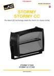
Le Maitre Ltd.
Stadium Hazer
Operating Manual
Introduction
The Le Maitre Stadium Hazer is the very latest device in our range of Hazing machines. Utilising a proven, patented
conversion technique this hazer can provide a truly awesome output and is eminently suited for large venues. At the same
time, electronic control of the output issue enables its use in smaller areas where rapid atmosphere fills are required.
The non-toxic fluid used to provide the unique haze form, departs from undesirable oil type use, and can as such, only be
converted by the advanced techniques employed. By maintaining a narrow band, cyclic temperature operation, consistent
micron sized particles are formed, creating the very best of atmospheric haze.
Multi direction capabilities combined with an electronically adjustable blower fan make this unit one of the most versatile and
self contained units on the market.
Virtually instant start up means that the Hazer can be rapidly deployed…. Extremely high output means that venue fill times
are extremely short.
The patented haze process is performed by a combination of high quality fluid and air pump control combined with a very
low mass (VLM) stainless steel conversion tube. The vlm tube is supplied with power via a microprocessor controlled switch
mode power supply and monitored with a fast reacting thermocouple. The construction allows the low cost vlm tube to be
replaced very easily and without specialised tools.
The Stadium Hazer is supplied in a rugged rolling flight case, and merely requires the lid to be removed for instant action. All
cables and fluid supply remain in this case for ease of use and transportation.
2
Safety Instructions
All users should make themselves aware of any national or local restrictions to the use of these types of machines in
applications involving public venues or areas.
Users should be aware of all regulations and advice on the use of Smoke and Haze machines.
The safe employment of this machine is strictly the responsibility of the user.
As with all vaporiser principle machines, exit nozzles will be very hot and capable of causing burns. Please take note of the
warning labels.
Do not touch or obstruct these nozzles.
Under adverse conditions, tiny particles of hot fluid could issue close to the machine – Never aim at persons or allow such
operating conditions to occur, and maintain a 3m safety clearance.
There are ventilation holes on the top and at the rear of the machine, these should not be covered or obstructed. Similarly the
internal fan inlet holes underneath the chassis cowl on the top of the main chassis.
The machine should be electrically earthed, and should never be operated or connected to an unsafe supply.
The machine should not be connected to a ‘noisy’ or spike laden power supply.
Spilled fluid or splashed fluid droplets can be a slip hazard. Comply with regulations when clearing or disposing of fluid.
Take note of any warning/advice notices attached to the fluid containers.
Do not operate the machine with any covers removed.
3
Stadium Hazer Specifications
Power Source Requirements – 230VAC 2000 Watt 50Hz
External Fusing
12AT ceramic
Internal Fusing
500mA PCB transformer
5AT ceramic smps 1
5AT ceramic smps 2
5AT ceramic power transformer
2AT ceramic air pump supply
VLM (very low mass) stainless steel replaceable vapour tube
Virtually Instant Operation
Fluid Capacity
Fluid Use -
10 Litres
Max
500cc / Hr.
Min
Blower Air Flow
Haze Flow direction
Control
50cc /Hr.
Max
600m3/h
Min
20m3/h
-30 degrees to 90 degrees
DMX 5122 channels
Haze and Fan
External 0-10v
Haze and Fan
Manual
Haze and Fan
Multiple Microprocessor Control
Modular Construction
Switched Mode Power Supplies for vapour tube energy
Can be supplied with detachable Control panel, or retro-adapted.
Machine Dimensions
680L
390W
350H
Flight Cased
1120L
500W
435H
4
Fluid Use
Please note that the fluid used with the stadium hazer is not like any other fluid used typically in smoke or hazer machines. It
is a high concentration fluid, which other machines are unable to process without incurring damage.
Only Le Maitre Ltd Hazer Fluid should be used. Use of other fluid will cause incorrect operation and could cause toxicity
issues.
Replacing fluid merely requires the changing the empty bottle for a new one. Use the screw lid to seal the used bottle and
dispose of correctly. Re filling the empty bottle is not advised as this can lead to the introduction of foreign particles which
may reduce the efficiency of the external in-line filter. If it is felt that there is a reduction in the performance of the machine
then this filter should be un-plugged from the silicon tubing and reversed washed. Never operate the machine with this filter
removed.
Any spillage should be cleaned away. The fluid does not require anything other than a water based cleanser.
5
Operating the Stadium Hazer
Switching the Stadium Hazer on using the mains switch at the rear of the machine will instigate an automatic cleaning
routine. This cycles the Hazer through an increased temperature mode in order to purge existing fluid and any surface matter
that may be present. The machine will then switch back into a state of readiness.
Should the fluid require priming into the machine, this will occur under normal operation, but can be achieved quicker by
having the haze set to maximum output.
Site the Machine in a desired position and use the side pull latch in order to set up the required haze output direction.
*(please see acceptable operating environment conditions) * (view pictorial operational guide).
For Manual operation set the Haze switch to ‘on’ and adjust the Haze control for the desired output ( 10 steps from Zero to
Max) and adjust the Fan output for the desired distance of dispersion.
(Note that Haze output steps 1 to 5 will only use one vapour tube.. this increases the overall operating efficiency, and allows
for optimum performance)
The Fan can be set to a sweep mode by rotating the fan speed control quickly between low – high – low within 2 seconds of
Haze switch on. The highest fan speed during the sweep will be as set by the fan speed control.
DMX512 merely requires that the address of the Haze channel be set via the rotary address selector switches, (control panel)
and the correct DMX signals applied. The subsequent channel will control the Blower fan speed. Please note that the DMX
address is set at machine switch on time. Any changes should therefore be set by switching the machine off and on again.
This prevents accidental re allocation.
0 – 10V operation can be achieved by applying these analog signals to pin2 and pin3 of the external input XLR connector on
the control Panel. All control signals prioritise to that of the highest level.
6
At the end of use, it is always best to switch the ‘haze’ switch off rather than just switching the mains power off. This allows
several cycles where no fluid is pumped into the system and prepares a cleared path ready for the next use. It is not
imperative, but prevents possible fluid spitting and undesirable haze output and the next power up time.
It is not advisable to leave full fluid bottles within the flight case if rough travel is expected, although under normal
circumstances and with secure bottle caps, the case has been designed for this purpose. Spare bottle caps can be kept in the
free storage area. Two fixed conduit tubes within the same area can be used to protect the bottle fluid feed tubes whilst
travelling.
The fluid fill tubes can be cleaned with a damp cloth before storing.
If external power fans/blowers are to be used then these should not be directed towards the output nozzle section, but
rather assist in the natural direction of hazing flow. Directing powerful air flow towards the output area could cause a
disruption to the temperature sensing mechanisms and result in condensing particles being issued.
7
Operating Environment
Although the Stadium Hazer has undergone extreme temperature and humidity tests, such conditions should not be
continuous.
The device is an electromechanical assembly containing electronic and mechanical devices. All such devices have reduced life
spans under adverse temperature and humidity conditions.
It is always wise to minimise ‘risky’ operating environments, and provide the machine with similar conditions as would be
applicable to any other electronic apparatus.
Good conditions include.
Dry – Free from dust etc – stable – non vibrating – non flammable surroundings – well ventilated – ‘normal temperature’ non haze re circulation area.
8
Maintenance
To instigate additional cleaning cycles, switch the machine off, and then on again.
Depending on the amount and nature of use, the vaporiser tubes may need physically cleaning or replacement. Since the
tubes are ‘straight’ in form, a push rod cleaning type tool can be used to clear any excess formations.
Occasional emission of small glowing carbon particles during the cleaning process indicate that this excess formation should
be cleared.
Replacing these tubes is merely a matter of removing the top cover on the moving arm, releasing the tube retaining bolts,
fluid tube and sensor plug, and fitting a new unit in place. ( see diagrams)
With the arm in its lowest position, remove the 8 M3.5 cover bolts and cover
Snip the nylon ties holding the silicon feed tubes onto the pipe and push the tubing off.
Release the M4 lock nut on the front brass terminal block, and undo the M4 cap head bolt using a driver size 3 hex key.
Release, but do not fully undo, the M4 bolt securing the terminal clamp to the input end of the tube. ( Phillips screwdriver and
small M4 spanner)
Unplug the appropriate thermocouple lead. (centre tube to lower connector, outer tube to upper connector)
Release the front end of the tube from the brass connector block and pull the tube forward to remove.
Replace the tube in the reverse order and check for correct operation without leakage etc. The tube may need a few hours to
settle in.
Make sure all air vents are free from restrictions
Keep the machine clean and free of debris or fluid that could enter the machine and cause problems.
9
Do not apply excessive force to the moveable haze ‘arm’ or let it drop without support.
Keep the fluid filter clean.
If the machine is to be in a fixed installation, make sure that it meets the working environmental conditions, and that it is
monitored by qualified personnel.
10
Pictorial Guides
Rear machine – mains switch.
Fluid Filters
11
Control Panel
Arm Lock Adjustment
12
Tube Replacement – Assistive Pictures.
Top cover removed.
Twin tube layout indicating front and rear fixings. Temperature sensor plug in points.
13
LE MAITRE WARRANTY CONDITIONS
To be supplied.
14