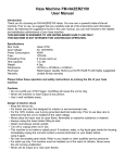
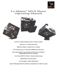
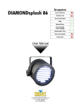
1
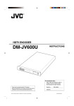
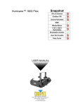
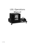
Snapshot Use on Dimmer Outdoor Sound Activated DMX Master/Slave 115 V / 230 V Switch Resettable Breaker User Serviceable Duty Cycle User Manual 3000 N 29th Ct, Hollywood, FL 33020 U.S.A. (800) 762-1084 – (954) 929-1115 FAX (954) 929-5560 www.chauvetlighting.com TABLE OF CONTENTS 1. BEFORE YOU BEGIN ................................................................................................................................................... 3 WHAT IS INCLUDED ................................................................................................................................................................................ 3 UNPACKING INSTRUCTIONS .................................................................................................................................................................... 3 MANUAL CONVENTIONS ......................................................................................................................................................................... 3 ICONS .................................................................................................................................................................................................. 3 SAFETY INSTRUCTIONS .......................................................................................................................................................................... 4 2. INTRODUCTION ........................................................................................................................................................... 5 FEATURES ............................................................................................................................................................................................ 5 DMX CHANNEL SUMMARY ..................................................................................................................................................................... 5 PRODUCT OVERVIEW............................................................................................................................................................................. 6 PRODUCT DIMENSIONS .......................................................................................................................................................................... 7 3. SETUP .......................................................................................................................................................................... 8 AC POWER........................................................................................................................................................................................... 8 BREAKER RESET ................................................................................................................................................................................... 8 LED-ILLUMINATED TANK ........................................................................................................................................................................ 8 FIXTURE LINKING................................................................................................................................................................................... 9 Data Cabling ............................................................................................................................................................. 9 DMX Data Cable ....................................................................................................................................................... 9 Cable Connectors ..................................................................................................................................................... 9 3-Pin to 5-Pin Conversion Chart .............................................................................................................................. 10 Setting up a DMX Serial Data Link .......................................................................................................................... 10 4. OPERATING INSTRUCTIONS .................................................................................................................................... 11 CONFIGURING THE STARTING ADDRESS ................................................................................................................................................ 11 CONTROL PANEL FUNCTIONS ............................................................................................................................................................... 11 CONTROL PANEL FUNCTIONS (CONT.) ................................................................................................................................................... 12 DMX ....................................................................................................................................................................... 12 DMX CHANNEL VALUES ...................................................................................................................................................................... 12 ADJUSTABLE BLOWER ANGLES ............................................................................................................................................................. 12 LED INDICATORS ................................................................................................................................................................................ 13 AUTO CUT-OFF FEATURE .................................................................................................................................................................... 13 GENERAL TROUBLESHOOTING .............................................................................................................................................................. 14 CONTACT US ...................................................................................................................................................................................... 14 5. APPENDIX .................................................................................................................................................................. 15 DMX PRIMER ..................................................................................................................................................................................... 15 GENERAL MAINTENANCE...................................................................................................................................................................... 15 Maintenance ........................................................................................................................................................... 16 Storage ................................................................................................................................................................... 16 RETURNS PROCEDURE ........................................................................................................................................................................ 17 CLAIMS .............................................................................................................................................................................................. 17 TECHNICAL SPECIFICATIONS ................................................................................................................................................................ 18 Arena Hazer™ 2 User Manual 2 12/10/2009 5:22 PM 1. BEFORE YOU BEGIN What is included 1 x Arena Hazer™ 2 1 x Wired LCD remote 1 x Warranty Card 1 x User Manual Unpacking Instructions Immediately upon receiving a fixture, carefully unpack the carton, check the contents to ensure that all parts are present, and have been received in good condition. Notify the shipper immediately and retain packing material for inspection if any parts appear damaged from shipping or the carton itself shows signs of mishandling. Save the carton and all packing materials. In the event that a fixture must be returned to the factory, it is important that the fixture be returned in the original factory box and packing. Manual Conventions CHAUVET manuals use the following conventions to differentiate certain types of information from the regular text. MEANING CONVENTION [10] A DIP switch to be configured <Menu> A key to be pressed on the fixture’s control panel 1~512 A range of values 50/60 A set of values of which only one can be chosen Settings MENU > Settings ON A menu option not to be modified (for example, showing the operating mode/current status) A sequence of menu options to be followed A value to be entered or selected Icons This manual uses the following icons to indicate information that requires special attention on the part of the user. MEANING ICONS This paragraph contains critical installation, configuration or operation information. Failure to comply with this information may render the fixture partially or completely inoperative, cause damage to the fixture or cause harm to the user. This paragraph contains important installation or configuration information. Failure to comply with this information may prevent the fixture from functioning correctly. This paragraph reminds you of useful, although not critical, information. Arena Hazer™ 2 User Manual 3 12/10/2009 5:22 PM Safety Instructions Please read these instructions carefully. It includes important information about the installation, usage and maintenance of this product. Please keep this User Manual for future consultation. If you sell the unit to another user, be sure that they also receive this instruction booklet. Always make sure that you are connecting to the proper voltage, and that the line voltage you are connecting to is not higher than that stated on the decal or rear panel of the fixture. This product is intended for indoor use only! To prevent risk of fire or shock, do not expose fixture to rain or moisture. Make sure there are no flammable materials close to the unit while operating. The unit must be installed in a location with adequate ventilation, at least 20 in (50 cm) from adjacent surfaces. Be sure that no ventilation slots are blocked. Always disconnect from power source before servicing or replacing fuse and be sure to replace with same fuse source. Secure fixture to fastening device using a safety chain. Maximum ambient temperature (Ta) is 104° F (40° C). Do not operate fixture at temperatures higher than this. In the event of a serious operating problem, stop using the unit immediately. Never try to repair the unit by yourself. Repairs carried out by unskilled people can lead to damage or malfunction. Please contact the nearest authorized technical assistance center. Never connect the device to a dimmer pack. Make sure the power cord is never crimped or damaged. Never disconnect the power cord by pulling or tugging on the cord. Avoid direct eye exposure to the light source while it is on. Use only water-based fog fluid. Do not use oil based fluid. Use only Chauvet® HJU fluid! Arena Hazer™ 2 User Manual 4 12/10/2009 5:22 PM 2. INTRODUCTION Features 2-channel DMX professional hazer Adjustable haze output via wired remote or DMX Adjustable blower speed via wired remote or DMX Additional Features Adjustable blower angle 3-pin and 5-pin DMX connections Wired remote with LCD screen 2.5 L tank capacity 8 min heat up Low fluid indicator and auto shut down LED-illuminated tank Water-based hazer DMX Channel Summary CHANNEL FUNCTION 1 Blower 2 Haze Arena Hazer™ 2 User Manual 5 12/10/2009 5:22 PM Product Overview Power switch Power in Breaker Carrying handle Wired remote with LCD backlit control panel 3-pin DMX in/out Blower 5-pin DMX in/out LED-illuminated tank Door latch Use Chauvet® HJU fluid only! Arena Hazer™ 2 User Manual 6 12/10/2009 5:22 PM Product Dimensions Arena Hazer™ 2 User Manual 7 12/10/2009 5:22 PM 3. SETUP AC Power This fixture runs on either 115 VAC, 60 Hz, or 230 VAC, 50 Hz. Before powering on the unit, make sure the line voltage to which you are connecting it is within the range of accepted voltages. Always connect the fixture to a switched circuit. Never connect the fixture to a rheostat (variable resistor) or dimmer circuit, even if the rheostat or dimmer channel is used only as a 0 to 100% switch. To determine the power requirements for a particular fixture, see the label affixed to the back plate of the fixture or refer to the fixture’s specifications chart. A fixture’s listed current rating indicates its average current draw under normal conditions. Always connect the fixture to a circuit with a suitable electrical ground. Breaker Reset This product is equipped with a breaker on the main power input, located on the exterior of the back panel. In the event that this breaker trips, you may reset it very easily. 1. Unplug the product from the power outlet. 2. Allow to cool for 5~15 min. 3. Press on the breaker button until it remains in place. In the event that this breaker will not reset, contact CHAUVET for troubleshooting. The fixture may need to be serviced. LED-Illuminated Tank The fluid tank on this hazer is equipped with LEDs, in order to provide visual fluid level indication, as well as to provide the readiness of the hazer. When the color is at red, it means that the hazer is heating. In most circumstances, this will not prevent the hazer from operating. During operation, the color of the tank will periodically change between blue and red. When initially powering on the hazer, the tank color will be red. This means that it must heat up to operating temperatures. Once the maximum operating temperature is reached, the tank color will be blue. This hazer is designed to work continuously at maximum haze output without the need to wait for the heater to warm up periodically. When the tank is empty, the LEDs will flash blue to indicate the auto cut-off feature has been activated. Arena Hazer™ 2 User Manual 8 12/10/2009 5:22 PM Fixture Linking You will need a serial data link to run light shows of one or more fixtures using a DMX controller or to run synchronized shows on two or more fixtures set to a master/slave operating mode. The combined number of channels required by all the fixtures on a serial data link determines the number of fixtures the data link can support. Fixtures on a serial data link must be daisy chained in one single line. To comply with the EIA485 standard, no more than 32 fixtures should be connected on one data link. Connecting more than 32 fixtures on one serial data link without the use of a DMX optically-isolated splitter may result in deterioration of the digital DMX signal. Maximum recommended serial data link distance: 500 m (1640 ft) Maximum recommended number of fixtures on a serial data link: 32 Data Cabling To link fixtures together you must obtain data cables. You can purchase CHAUVET certified DMX cables directly from a dealer/distributor or construct your own cable. If you choose to create your own cable please use data-grade cables that can carry a high quality signal and are less prone to electromagnetic interference. DMX Data Cable Use a Belden© 9841 or equivalent cable which meets the specifications for EIA RS-485 applications. Standard microphone cables cannot transmit DMX data reliably over long distances. The cable must have the following characteristics: Type: shielded, 2-conductor twisted pair Maximum capacitance between conductors: 30 pF/ft Maximum capacitance between conductor and shield: 55 pF/ft Maximum resistance: 20 ohms/1000 ft Nominal impedance: 100 ~ 140 ohms Cable Connectors Cabling must have a male XLR connector on one end and a female XLR connector on the other end. 1 3 2 DMX connector configuration COMMON INPUT 1 3 2 1 3 2 DMX + DMX - Resistance 120 ohm ¼ W between pin 2 (DMX -) and pin 3 (DMX +) on the output of the last fixture. OUTPUT To avoid signal transmission problems and interference, it is always advisable to connect a DMX signal terminator. Do not allow contact between the common and the fixture’s chassis ground. Grounding the common can cause a ground loop, and your fixture may perform erratically. Test cables with an ohm meter to verify correct polarity and to make sure the pins are not grounded or shorted to the shield or each other. Arena Hazer™ 2 User Manual 9 12/10/2009 5:22 PM 3-Pin to 5-Pin Conversion Chart If you use a controller with a 5-pin DMX output connector, you will need to use a 5-pin to 3-pin adapter. The chart below details a proper cable conversion: 3-PIN TO 5-PIN CONVERSION CHART Conductor 3-Pin Female (Output) 5-Pin Male (Input) Ground/Shield Pin 1 Pin 1 Data ( - ) signal Pin 2 Pin 2 Data ( + ) signal Pin 3 Pin 3 Not used Pin 4 Not used Pin 5 Setting up a DMX Serial Data Link Universal DMX Controller 1. Connect the (male) 3-pin connector side of the DMX cable to the output (female) 3-pin connector of the controller. 2. Connect the end of the cable coming from the controller which will have a (female) 3-pin connector to the input connector of the next fixture consisting of a (male) 3-pin connector. This drawing provides a general illustration of the DMX input/output panel of a lighting fixture. 3. Then, proceed to connect from the output as stated above to the input of the following fixture and so on. Continue the link Arena Hazer™ 2 User Manual 10 12/10/2009 5:22 PM 4. OPERATING INSTRUCTIONS Configuring the Starting Address Each fixture requires a starting address from 1~512. A fixture requiring one or more channels for control begins to read the data on the channel indicated by the starting address. For example, a fixture that uses seven DMX channels and is addressed to start on DMX channel 100, will read data from channels: 100, 101, 102, 103, 104, 105 and 106. Choose the starting addresses for each fixture so that the channels used do not overlap. In addition, you should note the starting address selected for future reference. The Arena Hazer™ 2 fixture uses two DMX channels. If this is your first time using DMX, we recommend reading the “DMX Primer” section in the “Appendix”. Control Panel Functions Access control panel functions using the six buttons located underneath the LCD Display on the included wired remote. Button Function <FAN/ADDRESS +/-> Used to select incremental fan speed, as well as select the DMX address in address selection mode <HAZE +/-> Used to select incremental haze output <FULL> Latching full fan speed and haze output <FUNCTION> Used to select to DMX address selection mode The Control Panel shows the current state of the unit. It also has a sub-menu, which is used for setting the DMX starting address. You may select any combination of incremental fan speed and haze output, using the respective <+> and <-> buttons. If an immediate full fan speed and maximum haze output is desired, press <FULL>. This is a latching button. Arena Hazer™ 2 User Manual 11 12/10/2009 5:22 PM Control Panel Functions (cont.) DMX This operating mode will allow you to control the Arena Hazer™ 2 with an external DMX controller. You must set the starting address for this mode. If this is your first time using DMX, then it is recommended that you refer to the “DMX Primer” section in the “Appendix” of this manual. 1. 2. 3. Press <FUNCTION>. Using <FAN/ADDRESS> <+> and <-> buttons, select the desired DMX address. Press <FUNCTION>. DMX Channel Values CHANNEL VALUE FUNCTION 1 000 255 Blower 0~100% 2 000 255 Haze 0~100% Adjustable Blower Angles The blower output angle may be adjusted by using a knob located on the side of the hazer. 1. 2. 3. Loosen the knob by turning it counter-clockwise. Using the knob as a handle, adjust the angle either up or down. Tighten the knob by turning it clockwise. Blower Angle Adjustment knob Arena Hazer™ 2 User Manual 12 12/10/2009 5:22 PM LED Indicators When the fluid is low in the hazer, the low fluid indicator (shown as NO FLUID on the hazer) will light solid. When the hazer detects DMX signal, the DMX indicator (shown as DMX OK on the hazer) will light solid. Auto Cut-Off Feature This product has a safety feature to keep the machine from becoming damaged. This is referring to the operation of the pump. When the fluid tank is empty, the pump will still operate for a short time until all of the fluid has been removed from the system. Then, it will sense that there is no fluid and will automatically stop the haze output. An indication that this has occurred is when the LOW FLUID LED is lit and the tank LED is flashing blue. It will take approximately 30 seconds to 1 minute for this feature to engage once the fluid has emptied from the tank. In order for the hazer to automatically reset, the trigger must be released. This may be from the wired remote, or via a DMX controller. If it is via a DMX controller, then the DMX channel will have to be brought to a value of 000 (0%) in order to allow the hazer to reset itself. Once the tank has been refilled with fog fluid, you may resume using the hazer. The auto cutoff will automatically reset. The auto cut-off feature will not function if the wired remote is set to a haze output level less than 3 or if the DMX value (In DMX mode) is set below 080. Do not run the hazer without fluid. Failure to follow these instructions may void the warranty. When the tank is empty, the LEDs will flash blue to indicate the auto cut-off feature has been activated. Arena Hazer™ 2 User Manual 13 12/10/2009 5:22 PM General Troubleshooting SYMPTOM POSSIBLE CAUSE(S) Breaker/Fuse keeps blowing Device does not power up Fixture is not responding to DMX Loss of signal POSSIBLE ACTION(S) Excessive circuit load Check total load placed on the electrical circuit Short circuit along the power wires Check for a short in the electrical wiring (internal and/or external) No power Check for power at power outlet Loose power cord Check power cord Wrong DMX addressing Check Control Panel and unit addressing Damaged DMX cables Check DMX cables Wrong polarity settings on the controller Check polarity switch settings on the controller Loose DMX cables Check cable connections Faulty DMX interface Replace DMX input Faulty Main PCB Replace Main PCB Non DMX cables Use only DMX compatible cables Bouncing signals Install terminator as suggested Long cable / Low level signal Install amplifier right after fixture with strong signal Too many fixtures Install an optically coupled DMX splitter after unit #32 Interference from AC wires Keep DMX cables separated from power cables or black lights If you still have a problem after trying the above solutions, please contact CHAUVET Technical Support. Contact Us World Wide General Information CHAUVET 3000 North 29th Court Hollywood, FL 33020 voice: 954.929.1115 fax: 954.929.5560 toll free: 800.762.1084 Technical Support CHAUVET 3000 North 29th Court Hollywood, FL 33020 voice: 954.929.1115 (Press 4) fax: 954.929.5560 (Attention: Service) World Wide Web www.chauvetlighting.com Arena Hazer™ 2 User Manual 14 12/10/2009 5:22 PM 5. APPENDIX DMX Primer There are 512 channels in a DMX connection. Channels may be assigned in any manner. A fixture capable of receiving DMX will require one or a number of sequential channels. The user must assign a starting address on the fixture that indicates the first channel reserved in the controller. There are many different types of DMX controllable fixtures and they all may vary in the total number of channels required. Choosing a start address should be planned in advance. Channels should never overlap. If they do, this will result in erratic operation of the fixtures whose starting address is set incorrectly. You can however, control multiple fixtures of the same type using the same starting address as long as the intended result is that of unison movement or operation. In other words, the fixtures will be slaved together and all respond exactly the same. DMX fixtures are designed to receive data through a serial Daisy Chain. A Daisy Chain connection is where the DATA OUT of one fixture connects to the DATA IN of the next fixture. The order in which the fixtures are connected is not important and has no effect on how a controller communicates to each fixture. Use an order that provides for the easiest and most direct cabling. Connect fixtures using shielded two conductor twisted pair cable with three pin XLR male to female connectors. The shield connection is pin 1, while pin 2 is Data Negative (S-) and pin 3 is Data positive (S+). General Maintenance To maintain optimum performance and minimize wear, fixtures should be cleaned frequently. Usage and environment are contributing factors in determining frequency. As a general rule, fixtures should be cleaned at least twice a month. Dust build up reduces light output performance and can cause overheating. This can lead to reduced lamp life and increased mechanical wear. Be sure to power off fixture before conducting maintenance. Unplug fixture from power. Use a vacuum or air compressor and a soft brush to remove dust collected on external vents. Clean all glass when the fixture is cold with a mild solution of glass cleaner or Isopropyl Alcohol and a soft lint free cotton cloth or lens tissue. Apply solution to the cloth or tissue and drag dirt and grime to the outside of the lens. Gently polish optical surfaces until they are free of haze and lint. The cleaning of external optical lenses and/or mirrors must be carried out periodically to optimize light output. Cleaning frequency depends on the environment in which the fixture operates. Damp, smoky or particularly dirty surroundings can cause greater accumulation of dirt on the unit’s optics. Clean with soft cloth using normal glass cleaning fluid. Clean the external optics at least every 20 days. Clean the fixture at least every 30/60 days. Always dry the parts carefully after cleaning them. Never spin a fan using compressed air. Arena Hazer™ 2 User Manual 15 12/10/2009 5:22 PM Warning! This Haze Machine must only be used with Chauvet HJU Haze Fluid. Failure to use the proper fluid with this product may cause damage to the product and may also void the Chauvet warranty. All haze machines are prone to clogging due to the thick consistency of the fog liquid and the high temperature at which it vaporizes. However, a properly maintained fog machine should provide years of reliable use. Cleaning your fog machine regularly will help reduce costly replacement and repair charges. Maintenance Do not allow the haze machine to become contaminated. After every 40 hours of continuous operation, it is recommended to run a cleaning solution composed of 80% distilled water and 20% white vinegar through the system to prevent the accumulation of particulate matter in the heating element. The recommended cleaning procedure is as follows: 1. 2. 3. 4. Empty all fog liquid from the machine. Add cleaning solution to tank. Plug unit in and begin warm up. Run the unit in a well-ventilated area until the tank is almost empty. Do not allow the pump to run dry. Replace nozzle. Cleaning is now complete. Refill with fog liquid. Run the machine for 30-60 seconds, or until all fluid has been removed from the system. Storage When storing the machine, run distilled water (not tap water) through the system as described in the cleaning regiment above. This will help avoid any particles condensing inside the pump or heater. Then, empty the fluid reservoir. Run the machine for 30-60 seconds, or until all fluid has been removed from the system. It is required to test-run the machine on a monthly basis in order to achieve its best hazing condition. After testing, be sure to clean and drain the system prior to storing. Never store the machine with fluid in the lines. Never place the hazer on any flammable material (i.e. carpet, fabric etc.) during operation. All fog/hazer machines should always be on a non-flammable surface, such as concrete or tile. All haze machines are capable of setting off smoke detectors, as they may detect the water-based particles as smoke. Never disable a smoke detector. Arena Hazer™ 2 User Manual 16 12/10/2009 5:22 PM Returns Procedure Returned merchandise must be sent prepaid and in the original packing; call tags will not be issued. Package must be clearly labeled with a Return Merchandize Authorization Number (RMA #). Products returned without the RMA # will be refused. Call CHAUVET and request an RMA # prior to shipping the fixture. Be prepared to provide the model number, serial number and a brief description of the cause for the return. Be sure to pack fixture properly; any shipping damage resulting from inadequate packaging is the customer’s responsibility. As a suggestion, proper UPS packing or double-boxing is always a safe method to use. CHAUVET reserves the right to use its own discretion to repair or replace product(s). If you are given an RMA #, please include the following information on a piece of paper inside the box: 1) Your name 2) Your address 3) Your phone number 4) The RMA # 5) A brief description of the symptoms Claims Damage incurred in shipping is the responsibility of the shipper; therefore, the damage must be reported to the carrier upon receipt of merchandise. It is the customer's responsibility to notify and submit claims with the shipper in the event that a fixture is damaged due to shipping. Any other claim for items such as missing component/part, damage not related to shipping, and concealed damage, must be made within seven (7) days of receiving merchandise. Arena Hazer™ 2 User Manual 17 12/10/2009 5:22 PM Technical Specifications WEIGHT & DIMENSIONS Length ........................................................................................................................ 18.1 in (462 mm) Width.......................................................................................................................... 12.7 in (322 mm) Height ........................................................................................................................ 11.8 in (303 mm) Weight....................................................................................................................... 37.7 lbs (17.1 kg) POWER AC power ...................................................................................... 115 VAC, 60 Hz or 230 VAC, 50 Hz Breaker .................................................................................................. 15 A @ 115 V or 9 A @ 230 V Power Consumption @ 120 V .............................................................................. 1,748 W, 14.8 A max Power Consumption @ 230 V ................................................................................ 1,502 W, 6.5 A max PERFORMANCE Fluid consumption ................................................................................................................. 47 ml/min Output ................................................................................................................................... 3,500 cfm THERMAL Maximum ambient temperature ...................................................................................... 104° F (40° C) CONTROL & PROGRAMMING Data input (3-pin) .................................................................................. locking 3-pin XLR male socket Data output (3-pin) ............................................................................. locking 3-pin XLR female socket Data pin configuration (3-pin) ................................................................. pin 1 shield, pin 2 (-), pin 3 (+) Data input (5-pin) .................................................................................. locking 5-pin XLR male socket Data output (5-pin) ............................................................................. locking 5-pin XLR female socket Data pin configuration (5-pin) ................................. pin 1 shield, pin 2 (-), pin 3 (+), pins 4+5 (not used) Protocols .................................................................................................................. USITT DMX512-A DMX Channels ....................................................................................................................................2 ORDERING INFORMATION Arena Hazer™ 2 .........................................................................................................ARENAHAZER2 WARRANTY INFORMATION Warranty ........................................................................................................... 2-year limited warranty Arena Hazer™ 2 User Manual 18 12/10/2009 5:22 PM