1
DLB-1200 Network Load Balancer User Manual
♦
Ethernet Indicator
♦
WAN 1 Indicator
♦
WAN 2 Indicator
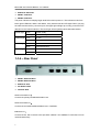
The power indicator is keeping bright while DLB-1200 is power on. The indicators order from
left to right be Ethernet, WAN 1 and WAN 2, every indicator has two LED lights. When you plug
the cable end into the any connector port, the upper light will light up to notify you that a link is
detected on the internal interface. The lower light will be sparkling while data transmission.
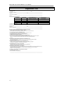
Power light Green
Sparkling
Ethernet light Green
Yellow
WAN 1 light Green
Yellow
WAN 2 light Green
Yellow
System ready
System staring
On line
Data transmission
On line
Data transmission
On line
Data transmission
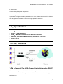
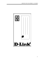
1-3-b、Rear Panel
♦
WAN 1 External Port
♦
WAN 2 External Port
♦
Ethernet Port
♦
DC Power Inlet
♦
Console Port
WAN 1 External Port:
Connect the primary Broadband Modem here.
WAN 2 External Port:
Connect the second Broadband Modem here, if available.
Ethernet Port:
Connect the PC, Hub or switch to this port. Both 10Base T and 100Base T connections can be
used simultaneously.
5