1
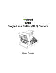
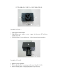
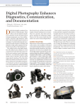
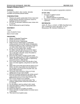
TeliCam
Intraoral Video Camera
User Manual
September 1996
DMT
DenMed Technologies, Inc.
1531 W. Orangewood Avenue
Orange, CA 92868
714-532-1107
Copyright © 1996 by DenMed Technologies, Inc.
All Rights Reserved
030-1025 XA
TeliCam User Manual
TABLE OF CONTENTS
The TeliCam Intraoral Camera
3
TELICAM INSTALLATION
4
TELICAM OPERATION
Powering On
Checking and Replacing Fiber Lamp
Front Panel Controls
Video and Capture Operation
Capturing Images
Quad Mode
Single/Quad Selection from Handpiece
6
6
6
6
7
7
8
8
HANDPIECE CONTROL
Changing Focal Position
Extraoral / Arch
Intraoral Detent
Extreme Close-Up
9
9
9
9
10
CONTAMINATION AND CLEANING
Disposable Sheath Barrier
Cleaning
11
11
11
CAPTURED IMAGE JITTER
Selecting Frame/Field Mode
Footswitch Operation
12
12
12
HITACHI MODE OPERATION
Hitachi Mode Troubleshooting
13
13
DMTI Technical Support
13
SPECIFICATIONS
14
ACCESSORIES
15
WARRANTY STATEMENT
16
©1996 DMT
Page 2 of 16
TeliCam User Manual
Figure 1
TeliCam IntraOral Camera showing handpiece and chassis.
The TeliCam Intraoral Camera
The TeliCam intraoral video camera is a cost-effective high performance dental imaging
system with advanced capabilities. Major features include a Teli camera processor,
renowned in the intraoral marketplace for excellent color rendition and contrast, a singlelens handpiece not requiring any lens change to view from close-up to extraoral, and
integrated video capture memory.
©1996 DMT
Page 3 of 16
TeliCam User Manual
TELICAM INSTALLATION
Unpack and inspect the TeliCam and any optional equipment received for any signs of
shipping damage. Save the packing materials in the event a return must be made. Locate
the supplied video and power cables, and become familiar with the connectors on the
equipment.
Prepare the location for the TeliCam equipment, and set the units in place. Note that in
custom installations adequate clearance must be provided for proper air flow around the
TeliCam in order to prevent possible overheating of the fiber light source, as shown in
Figure 2. Air is drawn in through the back of the TeliCam chassis, and heated air
exhausts out the bottom right side of the unit.
Figure 2
Installation inside TeliCam Cart showing proper clearance for air flow.
A thermal switch will shut off the fiber lamp in the event there is an overheating problem.
This will be the case if the air flow is blocked or limited.
The TeliCam is a video output device much like a typical camcorder or VCR, and must
be hooked to an appropriate video display for images to be seen. The TeliCam has video
output connectors for standard composite Video as well as S-Video (Y/C). Select the
appropriate output for your installation and hook up the corresponding video cables from
the back of the TeliCam to the video display.
Please refer to Figure 3 for a typical cart installation. Be sure to plug the TeliCam into
the appropriate building electrical outlet or power strip.
Note: The TeliCam is intended only to be used with third-wire grounded electrical
power. Do not defeat or alter the third-wire safety ground under any
circumstances.
©1996 DMT
Page 4 of 16
TeliCam User Manual
Figure 3
Typical Cart installation showing TeliCam-Printer-Monitor video cabling.
©1996 DMT
Page 5 of 16
TeliCam User Manual
TELICAM OPERATION
Powering On
Turn on the TeliCam by pressing “Power” on the left side of the front panel of the unit.
A green LED will light up on the power button, and other LEDs will light on the front
panel. At this point, the video monitor should show a dark gray screen with a faint black
cross in through the center. This is a display of the video memory, which is empty at
power up.
Pressing the “Light” button turns on the fiber optic light, and light should be seen
emanating from the tip of the handpiece. A corresponding LED will light on the “Light”
switch.
Checking and Replacing Fiber Lamp
If no fiber light is seen when the “Light” switch is depressed, then it is possible the fiber
lamp may have dislodged during shipping. Unplug the TeliCam, and turn it over to reach
the lamp door. Remove the lamp door as shown in Figure 4, and check to see that the
lamp is fully seated into the socket by gently pressing down on it until resistance is felt.
Replace the lamp door and reinstall the system.
Figure 4
Bottom of the unit showing the fiber lamp properly installed.
In the event the lamp must be replaced, remove the lamp by actuating the metal arm and
sliding the lamp up and out of the socket. Be sure to let the Lamp cool down before
touching if it has been in use for a period of time. Refer to the TeliCam Accessories for
reorder of the specific lamp type for your model.
Front Panel Controls
Many of the features of the TeliCam are controlled via the front panel of the unit, shown
in Figure 5. The front panel is made of material which is resistant to most common
clinical solutions, and can be easily cleaned by wiping with alcohol or standard cleaning
solutions. When activating the ‘Power’ and ‘Light’ switches, a mechanical toggle can be
©1996 DMT
Page 6 of 16
TeliCam User Manual
felt in addition to the visible LEDs. The remaining switches are momentary contact, and
actuation is indicated by the corresponding LED.
Figure 5
Front Panel of the TeliCam.
The TeliCam is capable of displaying either ‘Live’ or ‘Memory’ images on screen.
Additionally, the TeliCam can display either a ‘Single’ image or four ‘Quad’ images.
These modes are selected using the “Live/Memory” and “Single/Quad” toggles located
on the right side of the front panel.
Video and Capture Operation
The unit “wakes up” in ‘Quad mode’ displaying ‘Memory’. By pressing one of the
capture buttons on the camera handpiece, or the capture pedal, a live video image will be
seen on the video monitor. Releasing the button or pedal will freeze the image in one
quadrant of the screen. Pressing and releasing the button or pedal will then save images
into successive quadrants.
Pressing the “Live/Memory” button on the front panel will toggle the TeliCam between
display of the “Memory” image and a “Live” image. By switching to ‘Live mode’, a live
full-screen video image is displayed. Now, after a capture button or pedal is pressed,
upon release, the image will freeze for a second or two, and then switch back live. The
image has been captured into memory, but live video is still displayed on screen.
Selecting 'Memory’ from the front panel will then display the captured image on screen.
Capturing Images
There are two "capture" buttons on the TeliCam handpiece. When you are ready to start
capturing images, hold hand steady, then press down and lift up on either of the "capture"
buttons. This will freeze the picture. The captured picture will quickly return to live, and
can be retrieved by pressing "Memory" on the front panel. If this picture is undesirable,
simply press down and lift up on the “capture” button again and a new captured image
will appear. Pressing "Live" will return the TeliCam to live mode. Images may also be
©1996 DMT
Page 7 of 16
TeliCam User Manual
captured by keeping the TeliCam in "Memory" mode. Keep either handpiece button
depressed until ready, then release to capture.
Quad Mode
When ‘Quad’ mode is selected (default on power-up), successive images will be captured
into each of the four quadrants of the screen. A dimly-lit LED will indicate the next
quadrant to be captured. When a quadrant is captured, the TeliCam automatically cycles
to the next in sequence.
In the event you capture an undesirable picture in one of the quadrants, the four buttons
located located around the yellow LED on the front panel can be used select the quadrant
you wish to recapture. Press the appropriate "Quad" button. The corresponding LED
will light brightly, designating the quadrant which will be recaptured. Retake the new
picture until you get it right. Then press the same quadrant button again, and it will
toggle back dim indicating the next quadrant to be captured.
An example of the power of the TeliCam Quad mode is shown in Figure 6.
Figure 6
An example of four different views displayed simultaneously in Quad mode.
Single/Quad Selection from Handpiece
To change from ‘Single’ to ‘Quad’ mode using the handpiece, simply hold one of the
"capture" buttons down and press the other at the same time. Repeating this sequence
will return TeliCam to ‘Single’.
©1996 DMT
Page 8 of 16
TeliCam User Manual
HANDPIECE CONTROL
Changing Focal Position
There is a movable gold ring on the handpiece which is used to select focal position.
Simply pull or push the ring forward or back to set the desired focal position. This can
be done with one hand by gripping the hand piece and moving the ring with the thumb or
forefinger. The ring will move about 1.5mm. This will allow focusing on objects from
as close as 2mm to full face distance, and beyond, in one movement.
Extraoral / Arch
With the ring moved all the way forward (towards the tip of the camera), objects from
infinity in to about a full arch or smile will be in sharp focus, as shown in Figure 7.
Figure 7
Extraoral / Arch setting (ring forward).
Intraoral Detent
Moving the ring back towards the rear of the handpiece will bring the focus in to closer
ranges suitable for intraoral imaging. As the ring is moved back, a slight detent should
be felt. This detent is set to a nominal intraoral focal position where 1-2 teeth will be in
sharp focus, as shown in Figure 8. Most doctors will find that this position offers a
comfortable working position for normal oral examination.
©1996 DMT
Page 9 of 16
TeliCam User Manual
Figure 8
Intraoral Setting (ring at detent).
Extreme Close-Up
As the focal ring is moved further back, the range of focus will become closer and closer
to the target, and the corresponding image magnification will become higher,
approaching x120, as viewed on a 13” monitor. The same molar as in Figure 8 is shown
Figure 9, at high magnification.
Figure 9
Extreme close-up (ring moved to rear).
©1996 DMT
Page 10 of 16
TeliCam User Manual
CONTAMINATION AND CLEANING
Disposable Sheath Barrier
The TeliCam is designed to be used in conjunction with a disposable sheath to act as a
contamination barrier. Proper installation of the sheath is required to provide the clearest
possible image.
When inserting the tip of the camera into the sheath, be sure to keep the camera straight
and slide directly into the sheath without twisting. Be sure the camera is aimed down at
the paper backing of the sheath packaging in order that the clear window of the sheath
line up with the TeliCam lens window. Refer to Figure 10.
Figure 10
Properly Installed Disposable Sheath.
Cleaning
Care should be taken when cleaning the TeliCam. Do not soak the camera in any
solutions, or use any phenol-based disinfectants on the handpiece cable. It is suggested
that the handpiece be wiped down with cold sterile or alcohol using a cotton cloth or
swab.
If the lens window becomes contaminated, carefully clean with a swab and alcohol.
Avoid excessive amounts of any solution to remain on the window area.
©1996 DMT
Page 11 of 16
TeliCam User Manual
CAPTURED IMAGE JITTER
The TeliCam captures single images using both interlaced video fields (“Frame” mode)
to ensure maximum capture resolution, by default. If there is movement of the subject
during the time these two fields of video information are captured, then the captured
image will appear to ‘jitter” on screen.
To eliminate the possibility of capture jitter, it is possible to set the TeliCam to use only a
single field of video (“Field” mode) for capture. Using “Field” mode will eliminate most
jitter when capturing a single full-screen picture, but may result in lower resolution than
“Frame” mode under certain conditions.
Selecting Frame/Field Mode
Selecting ‘Field’ mode to stop image jitter is done by simply pressing one of the four
Quad buttons on the front panel. All four LEDs around the Quad will blink once,
indicating one ‘Field’ of video information. Pressing again toggles back to ‘Frame’
mode, the LEDs will blink twice indicating both interlaced video fields are being used.
On some older units, Frame/Field can only be selected after powering the TeliCam on in
a special manner:
•
With the power off, press and hold down any one of the four Quad buttons on the
TeliCam front panel.
•
While still pressing a Quad button, power on the TeliCam.
You will then notice all four Quad LEDs blinking until the Quad button is released. The
camera is now in “Frame” mode, but pressing any of the Quad buttons while viewing a
single image on screen will toggle the image to “Field”, and remove jitter. When
toggling from Frame to Field, the Quad LED’s will blink twice to indicate Frame mode,
and once for Field mode.
Footswitch Operation
Using the optional footswitch will also help to reduce jitter in captured images by
allowing a steadier hand hold on the handpiece. The optional footswitch uses the right
pedal to capture images, and the left pedal to toggle from Single to Quad mode. Simply
plug the footswitch into the footswitch connector located on the rear of the TeliCam,
shown in Figure 3.
©1996 DMT
Page 12 of 16
TeliCam User Manual
HITACHI MODE OPERATION
Provision has been made to tightly integrate the control of the optional Hitachi VY-170A
video printer into the TeliCam. By setting the TeliCam to “Hitachi” mode, it is possible
to capture in printer memory and initiate printing from the handpiece buttons or foot
switch. The Hitachi VY-170A must be linked to the TeliCam via an 8-pin Remote cable,
as shown in Figure 3. Simply connect the cable between the TeliCam Remote connector
located on the rear of the unit and the Remote connector located at the rear of the printer.
Power up the printer by pressing the "Operate" button on front panel (the green "ready"
light will flash at first, then stay on). Press TeliCam ‘Live’/’Memory’ button for about
two seconds, until all four ‘Quad’ lights turn on. The system is now in "Hitachi" mode.
Press the "Monitor" button on the Hitachi (green light on). Now, the TeliCam handpiece
buttons or the footswitch will control the Hitachi printer directly, and bypass TeliCam
memory. Capture images by pressing and releasing either hand piece button, or the
capture pedal, just as in normal TeliCam operation. Then to print, press both hand piece
buttons at once, or the right foot pedal.
To select how many images you would like to appear on the monitor, select the ‘Picture’
button located behind the Hitachi control panel door. This allows you to split the monitor
screen into multiple shots, such as 4 (Quad), or 16.
To leave "Hitachi" mode and return to "Teli Mode", press ‘Live’/’Memory’ again for
about two seconds, until the four ‘Quad’ lights go out. The TeliCam will now function
normally again, and the Hitachi printer will not be affected.
Hitachi Mode Troubleshooting
If you have followed the above steps and cannot get a picture on the screen:
•
•
•
•
Make sure the TeliCam is in "Live" mode (front panel).
Press the "Input" button on Hitachi, repeat until INPUT S appears.
Select VIDEO 3 by pressing "Video Select" inside door on front panel of the
monitor.
Double check cable hook-up.
DMT Technical Support
If you are experience difficulty in this or any other operational issues, please call DMT
Technical Support at (714)-532-1107.
©1996 DMT
Page 13 of 16
TeliCam User Manual
SPECIFICATIONS
General
• Intraoral Video Camera NTSC or PAL format
• Integrated Video Freeze Memory with Single/Quad view
• Integrated High Intensity Fiber Optic Light Source
• Handpiece or Footswitch Freeze Memory operation
• Spill resistant membrane switch Front Panel
• Direct Control of Hitachi VY-170A Printer via Remote Connector
Optical
• Focus Range from ~2mm to Infinity
• Intraoral High-Magnification (>120x on 13” monitor)
• Extraoral Full Face capability
• Optical Distortion <±0.5%
• <10mm Dia. Intraoral Tip
• >90mm Intraoral Reach
Video
• Video
• S-Video
Composite
Y(Luminance)
C(Chrominance)
1 Vpp, 75Ω (unbalanced), SYNC negative
1 Vpp, 75Ω
0.28 Vpp, 75Ω
Electrical Power Requirements
NTSC
• 85-136 VAC, 50-60 Hz, 200W Max
PAL
• 180-264 VAC (PAL), 50Hz, 200W Max
Size and Weight
• Chassis Size:
• Weight:
11”W x 9.75”D x 3.30”H
6.5 LB
Environmental (Operating)
• Temperature
5° C to 35° C (40° F to 95° F)
• Humidity
20% to 80% RH
©1996 DMT
Page 14 of 16
TeliCam User Manual
ACCESSORIES
The following TeliCam consumables and typical accessories can be ordered directly from
DMT by calling the tool free number 714-532-1107. Be sure to check with your sales
representative for other items not listed.
Consumables
Disposable Sheaths
Disposable Sheaths
50 pk
500 pk
Hitachi Print Film
Toshiba Print Film
50 pk
50 pk
Halogen Lamp
1 pk
GE Type ESD, 120V, 150W
Accessories
Footswitch, 2 Pedal
Hitachi Printer Remote
Cord, AC Power, 6’, US 3-Prong, F-M
Cord, Extension, 9’
Power Strip, 5 Outlet, 15’
Cable, Remote, 6’, 8-Pin MiniDIN
Cable, Remote, 20’, 8-Pin MiniDIN
Cable, Remote, 40’, 8-Pin MiniDIN
Cable, S-Video, 6’
Cable, S-Video, 20’
Cable, Video, 6’, RCA-RCA
Cable, Video, 6’, BNC-RCA
Wall Mount, 20” Monitor
Wall Mount, 13” Monitor
Pole Mount, PM1 (Universal)
Pole Mount, PM2
Pole Mount, Spacer
©1996 DMT
Page 15 of 16
TeliCam User Manual
DENMED TECHNOLOGIES, INC.
1531 West Orangewood Avenue
Orange, CA 92868
714-532-1107
WARRANTY STATEMENT
DMT warrants the TeliCam product as manufactured by DMT against defects in
craftsmanship and materials for one year from the date the product was delivered to the
original purchaser. Computer related hardware is warranted for 90 days. DMT, at its
discretion, will repair or replace any parts of the products (other than users manuals,
software and computer related hardware) that are defective in craftsmanship or materials
if the product is proven faulty within the one year warranty, provided DMT is given
notice in a timely manner. DMT will be responsible for shipping costs of any
repair/replacement parts for the first 30 days after receipt of a system. The customer will
be responsible for shipping costs for any replacement or repair of defective parts
thereafter.
If products are to be returned to DMT, the original customer must obtain an RMA
(Return Merchandise Authorization) number from DMT via telephone. If a return is
made after the first 30 days of delivery, the customer must include the RMA number on
the package and the customer must prepay all freight charges to return any product to a
DMT designated location. DMT will ship replacements freight collect on an exchange
basis to the customer. Products will become property of DMT that are returned to
DMT under this warranty. Only the warranty given by the manufacturer will apply in
respect to any system or part thereof not supplied by DMT, if any.
This limited warranty excludes video light bulbs and does not cover damage which is due
to: 1) any defects in any product or part not supplied by DMT as part of the system; 2)
fine tuning, relocation, modification or repair by other than DMT authorized personnel;
3) improper maintenance or installation, carelessness, or negligence or any cause other
than ordinary applications, industrial, commercial or personal; 4) any statements made
about DMT products by regional offices, dealers, distributors, agents or salespeople
unless confirmed in writing by a DMT Officer, or; 5) damage which occurs in shipment
to or from Customer.
DMTs’ liability shall not exceed price of the individual piece whose loss or defect is the
basis of the claim. DMT is not liable for loss of use of facility, loss of profits, loss of
use of equipment or other incidental consequential damages. DMT is free of obligation
beyond its standard warranty with regards to changes made in system component
hardware by the manufacturer of that hardware. Without prior notice DMT reserves the
right to make changes in its system hardware at any time. This limited warranty shall
constitute the entire limited warranty and is granted by DMT instead of any or all or all
other written, oral, implied or statutory warranties.
©1996 DMT
Page 16 of 16