1
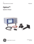
Read this manual carefully and follow the instructions contained in it. CAUTION and NOTE
are words which convey special meanings. Where they are used in this manual it is recommended
to read carefully the associated messages to ensure safe and effective use of the product.
Meaning of Symbols
OPTICA
SAFETY STANDARDS
WARNING: personal safety of patient of doctor could be involved.
CAUTION: observance of certain procedures or precautions is obligatory to avoid
damage to the product.
NOTE
: could indicate or clarify special information concerning operation of
the product.
Refer to annexed documents.
Type BF component.
-
Avoid installing the system in a position subject to magnetic force or vibrations or capable
of harming the equipment physically.
- Before installation, make sure a correct power source is available for the system.
- Make sure the other equipment is far from this device, which produces high voltage at high
frequency in addition to electromagnetic waves. This device could cause noise or disturb
operation.
- The positioning of this equipment must be suited to electronic equipment. High
temperatures, changes in humidity and direct sunlight as well as chemicals and suspended
dust could harm the system.
- After use, always keep the lens clean by careful use of swabs or soft cloth soaked in
alcohol. A dirty lens could cause fuzzy images.
- If this equipment does not operate correctly, consult our Service Department.
- Hygiene requires that the telecamera be covered with a disposable plastic sheath conforming
to EC or FDA standards.
NOTE: Equipment and accessories connected to the analog and digital interfaces must be
certified in accordance with the respective EN standards (for example, EN 60950 for data
processing equipment and EN 60601-1 for medical equipment). In addition, all configurations
must be in conformity with the system standard EN 60601-1-I:1993. Whoever connects
other equipment to the signal input or output parts is configuring a medical system and
consequently responsible that said system be in conformity with the requirements of the
system standard EN 60601-1-I:1993.In case of doubt, consult our Service Department.
9
OPTICA
TELECAMERA
fig.1
1. Focusing: move to F (far) for distant focusing, to N (near) for close-up.
2. MEM/LIV Button: for stopping image or for automatic white balancing adjustment.
3. Frame/Field Button: Frame- monitoring still image
(high resolution mode)
Field- Live image monitoring
(to avoid image distortion)
4. Telecamera outlet: connect the telecamera outlet to “CAMERA/IN”, OPTICA BOX or
TRANSITION CABLE for the embedded model.
STAND ALONE MODEL
Parts supplied:
Optica base – Telecamera handpiece – Image stop pedal – Power cable – RCA Video cable
S-VHS cable – Protective sheath – Instruction Manual.
Description of connectors:
3
1
7
2
fig.2
1.
10
2.
3.
4.
5.
6.
7.
fig.3
6
Telecamera Housing: place telecamera handpiece here when telecamera not in use
(power is removed).
Camera in: Connector for telecamera.
Video out: Composite video signal outlet.
S-VHS out: S-video signal outlet.
Freeze: Connector for Image Stop Pedal.
Power-in: Power supply connector.
Main ON-OFF Switch: Power.
4
5
OPTICA
STAND ALONE INSTALLATION
1. Connect the telecamera outlet to the CAMERA IN connector, then connect the VIDEO
OUT outlet to the VIDEO-IN inlet of the monitor.
Alternatively connect to S-VHS In for a better high resolution image.
2. Connect power cable to mains.
3. Turn on Monitor and Base Power Supply Switch.
NOTE (applies to all models)
If no image is seen on the monitor, check that the cables are correctly connected.
-
11
If the image colors displayed on the monitor are not correct, perform white balancing as
follows:
Intraoral viewing: position telecamera on a white sheet at a distance of 2 or 3cm and
hold down FREEZE Button for 5 sec.
Extraoral viewing: position telecamera on a white sheet at a distance of 20 or 30cm
and hold down FREEZE Button for 5 sec.
To stop an image, briefly press FREEZE Button on telecamera probe.
To return to LIVE mode, press FREEZE button again.
After using the telecamera, turn off Base Power Supply Switch.
OPTICA
OPTICA BOX MODEL
Parts supplied
Optica BOX – Telecamera Handpiece – 4-pole Power Cable for PC – Power Cable Jack for
Monitor - S-VHS Cable for PC – RCA Cable for monitor- Handpiece holder – Protective
Sheath – Instruction Manual
Inlet-outlet description
7
fig.4
1
2
3
4
5
6
1. INTEGRATED PC Power Inlet
2. INTEGRATED PC Power Outlet
3. Monitor Power Inlet
4. Monitor Power Outlet
5. S-VIDEO output
6. Composite video signal output
7. Telecamera Connector
NOTE: The Optica Box must be installed on the monitor or the INTEGRATED PC
using the stickers supplied (FIG 5).
Optica Box
Telecamera
12
fig.5
OPTICA
INSTALLATION
MONITOR - OPTICA BOX CONNECTION
Description of monitor connectors
1a. Power Connector
for connection of Power Cable.
2a. Video In (RCA)
RCA Video-In Connector.
1a
2a
RCA cable
telecamera cable
Power cable jack
Descrption of Optica Box connectors
3
5
7
4
Power cable for monitor
6
S-VHS signal cable
Arm
Use the cables supplied for connection as follows:
- Power cable from arm with 3 of Optica Box.
- Power Connector on Monitor 1a with 4 of Optica Box using jack power cable.
- Video-In Connector on Monitor 2a with 6 of Optica Box using RCA cable.
- Video-In Connector on camera with 7 of Optica Box.
- S-VHS cable from arm wit 5 of Optica Box.
13
EMBEDDED MODEL
OPTICA
NOTE:
FOR OPTICA BOX CONNECTION INSTALLED ON INTEGRATED
PC, APPLY TO OUR SERVICE DEPARTMENT.
Description of parts supplied
Telecamera Handpiece - Power Cable - Transition Cable - Protective Sheath - Instruction
Manual.
TRANSITION CABLE
4
3
1
2
fig.8
Ø 18
Front Ring-nut for
cord fastening
rear Ring-nut for cord
fastening
5
To install cable, make a dia. 18 hole in the Dental Unit Panel
(maximum panel thickness 6mm)
Details
1. RCA Video-In out connector.
2. S-VHS Video out Connector.
3. Power board connector (12 V dc).
4. Image Stopping Cables.
5. Telecamera Connector.
Connect as follows:
• no. 1 to RCA Video-In input.
• no. 2 to S-VHS Video input.
• no. 3 to supplied Power Supply (or 12 V dc power).
• no. 4 to image stopping control (insulate unused cables).
• no. 5 to telecamera connector.
14
OPTICA
PROTECTIVE SHEATH
To use telecamera, place it in disposable protective sheath.
Remove protective upper part.
Hold sheath fast, insert telecamera between white
tab and paper while holding optical side towards
paper. Insert telecamera carefully until
headreaches end of sheath.
Do not force.
Press down slightly to tighten sheath.
Now the telecamera is protected and ready for
use.
Remove paper covering.
IMPORTANT
Make sure to insert telecamera with lens toward paper.
TROUBLESHOOTING
NO IMAGE ON DISPLAY
- Make sure power is (ON).
- Make sure all connectors are connected correctly.
- Make sure LEDs are lit.
IMAGE IS DARKER
- Make sure LEDs are lit.
- Adjust brightness and contrast of display.
- Check white balancing using MEM/LIV button.
15
Power supply
(to Stand Alone-o Embedded)
(to Optica Box)
Sensor type
Output signal type
Pixels
Signal
Horizontal resolution
White balancing
ELC
Output signal
Illumination type
Image stopping
Lenght of telecamera cable
Weight of telecamera handpiece
: 100-240 V, 50/60 HZ, 16 VA
: 12 V dc
: 1/4” SONY super HAD CCD TM
: PAL (or NTSC)
: 752(H) x 582(V)
: DSP
: 460 TV lines
: Automatic (hold button down for 5 seconds)
: On
: Composite: 1EA, S-Video: 1EA
: Very bright white
: 1 image (select frame/field button)
frame/field)
: 2.2 m
: 55 g
OPTICA
SPECIFICATIONS
Storage Conditions
Temperature
Humidity
Atmospheric pressure
: - 40°C a + 70°C
: 10% a 100% without condensate
: 500hPa a 1060 hPa
16