1
"DUO" UNIT; INSTRUCTIONS USE AND MAINTENANCE HANDBOOK
Summary
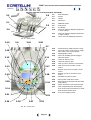
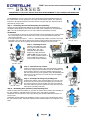
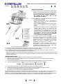
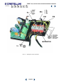
INSTALLING THE UNIT'S FEED BOX (Pict. 1.1, 1.2 and 1.3)
The service technician is also to secure at installation the supply box and make the hydro-pneumatic and wiring
connections as shown in Pict. 1.1, 1.2, 1.3
After disconnect the main power by the main switch, make the following operations:
1) Unscrew the three screws (part. 1.1.1 – pict. 1.1) and pull the protection (1.1.2); connect the main power cable, from
the floor; to the three terminal of the main board (marked with “LINE” – pict. 1.3); the brown cable have to be
connected to the terminal marked L∼, the blue cable to the terminal N∼, the yellow/green cable tothe terminal
(see pict. 1.3);
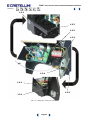
2) Insert the connectors (1.1.3 and 1.1.4 – pict. 1.1) and (1.4.10 and 1.4.11 – pict. 1.4A) of the cables coming off
from the proper seat on the electric circuit code E6000501, marked with CN1 – CN14 – CN19 – CN20.
3) Insert the water, pneumatic and discharge connections to the proper pipe fittings placed on the floor of the dental
cabinet (see .picts. 1.5 and 1.1 and the installation plan by 1:1 scale).
4) Connect the foot control following the instruction by the chapter “FOOT PEDAL CONNECTIONS”
5) For connect the Unit to a centralized suction-system, see chapter “CONNECTION TO A SUCTION-SYSTEM.
Before making the under mentioned operations, mount again the protection (1.1.2) and fix it through the screws (1.1.1),
then mount the cover (1.8.1) and fix it with the screw (1.8.2 – pict. 1.8).
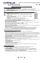
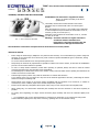
CONNECTION FOR FOOT PEDAL (Pict. 1.4A - 1.4B – 1.5)
- Get up the unit to the maximum height; (only for the ambidextrous version) after mount the plastic cover of the
chair base (1.4.2), insert throw the preposed chair cover hole terminals (1.4.8) foot pedal cable and fairlead (1.4.6).
- Insert terminals (1.4.8) to the proper connections on the circuit E6000501, and then connect the three tubes (1.5.1,
1.5.2, 1.5.3), with the proper inserts, to the correspondent tubes connected to the unit (see pict. 1.5).
- Connect the yellow/green cable fixing the ring-terminal cable (1.4.12) to one of the two heart-screws marked on pict.
1.4B with the bolt and the notched washer.
- Mount the cable clamp (1.4.7) under the fairlead (1.4.6) and fix it with proper screws (1.4.9); in case of an
ambidextrous unit, the cable clamp (1.4.7) must be fixing within the two screws (1.4.13) and the proper washers
(1.4.14) added with the unit.
- Assemble the plastic cover (1.4.2), blocking it with screws (1.4.3).
Page 91