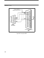
1
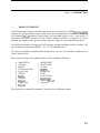
8430
Industrial Node PC/AT
Computer System
PIN 99663-001A
0 1994 XYCOM, INC.
Printed in the United States of America
Part Number 99663-001A
XYCOM
750 North Maple Road
Saline, Michigan 48 176-1292
(3 13)429-4971
XYCOM REVISION RECORD
Revision
Description
Date
A
Manual Released
10194
Trademark Information
Brand or product names are registered trademarks of their respective owners.
Copyright Information
This document is copyrighted by Xycom Incorporated (Xycom) and shall not be reproduced or copied without
expressed written authorization from Xycom.
The information contained within this document is subject to change without notice. Xycom does not guarantee the
accuracy of the information and makes no commitment toward keeping it up to date.
Address comments concerning this
manual to:
nxycom
wm
Part Number:
99663-OOIA
Technical Publications Department
750 North Maple Road
Saline, Michigan 48176-1292
TABLE OF CONTENTS
CHAPTER
TITLE
1
INTRODUCTION
1.1
1.2
1.3
1.4
1.4.1
1.4.2
1.5
Product Overview
Product Features
Unpacking the System
System Components
Front Panel Components
Input/Output Panel Components
Quick Start-up
PAGE
1-1
1-2
1-2
1-3
1-3
1-4
1-6
TESTING
2
2.1
2.2
2.3
Diagnostic Tests
Preparing for the Tests
Running the Tests
2-1
2-1
2-2
INSTALLATION
3
3.1
3.2
3.3
3.4
3.4.1
3.4.2
3.4.3
3.4.4
3.4.5
3.4.6
3.4.7
3.4.8
3.5
3.5.1
3.5.2
3.6
3.6.1
3.6.2
3.7
3.8
Introduction
Drive Access Panel
Preparing the System for Use
Installing the System into a Rack or Panel
Mounting Considerations
System Power
Excessive Heat
Excessive Noise
Excessive Line Voltage
Rack-mounting and Installing the 8430
Wall-mounting and Installing the 8430 (Side)
Wall-mounting and Installing the 8430 (Top)
Installing Internal Hardware Options
Solid State Disk Emulator Card
PC/AT Boards
Installing External Hardware Options
Keyboards
Serial Mouse
Installing MS-DOS
Derating the Power Supply
3-1
3-4
3-4
3-5
3-5
3-6
3-6
3-7
3-7
3-7
3-9
3-11
3-12
3-12
3-12
3-13
3-13
3-15
3-15
3-15
i
Table of Contents
PAGE
CHAPTER
TITLE
4
MAINTENANCE
4.1
4.2
4.2.1
4.2.2
4.2.3
4.2.4
4.3
Preventive Maintenance
Maintenance
Replacing the Fuse
Spare Parts List
Changing the Fan Filter
Replacing the Battery
Product Repair Program/Returning a Unit to Xycom
4-1
4-2
4-2
4-3
4-3
4-5
4-7
APPENDICES
A
B
SPECIFICATIONS
PINOUTS
LIST OF TABLES
PAGE
TABLE
TITLE
3-1
Derating Example
4- 1
Spare Parts List
4-3
A- 1
A-2
Environmental Specifications
Hardware Specifications
A- 1
A- 1
3-16
LIST OF FIGURES
PAGE
FIGURE
TITLE
1-1
1-2
Front Panel Components
8430-525X/6254 Input/Output Panel Components
1-3
1-4
2- 1
2-2
Serial Loopback Connections
Diagnostics Main Menu
2-2
2-3
3- 1
3-2
3-3
3-4
8430 Front Panel
8430 Back Panel
Internal System Components
Drive Access Panel
3-1
3-2
3-3
3-4
ii
8430 Manual
October 1994
LIST OF FIGURES (continued)
PAGE
FIGURE
TITLE
3-5
3-6
3-7
3-8
3-9
Installing the Rack-mounted 8430
8430 Wall-mounting Dimensions
Installing the Wall-mounted 8430 (side)
Installing the Wall-mounted 8430 (top)
8000-KB5 and 8000-KB6 Cutouts
4- 1
4-2
4-3
Fuse Holder/Access Door
Changing the Fan Filter
Changing the Battery
4-1
4-4
4-5
B- 1
B-2
B-3
B-4
B-5
B-6
B-7
B-8
Allen-Bradley KF2 Module
Allen-Bradley 1771-KG Module
9-pin Connection to Modbus 984 PLC
25-pin Connection to Modbus 984 PLC
Omron PLC
Texas Instruments Series 500 PLC
Texas Instruments 545 PLC
Westinghouse PLC
B- 1
B-2
B-3
B-4
B-5
B-6
B-7
B-8
3-8
3-9
3-10
3-1 1
3-14
iii
Chapter 1 - INTRODUCTION
1.1
PRODUCT OVERVIEW
The 8430 Industrial Computer Node Box puts the power and versatility of an IBM PC/AT-compatible
computer in a package that makes sense for the factory floor and other harsh environments. The Xycom
8430 Industrial PC/AT Computer System features an open-ended design to meet a wide variety of
applications when both a powerful PC and a durable industrial enclosure are required. The system
integrates the computer card cage, mass storage, and power supply in a truly industrial form factor.
The 8430 system includes a six-slot passive AT backplane, and hard and floppy disk drive facilities. The
open-architecture design accepts IBM PC-, XT-, or AT-compatible cards.
The system’s relocatable equipment module design allows easy access to the boards, switches, power
supply, and disk drives.
Many software packages are compatible with the 8430, including the following:
AIMAX-PLUS
Cellworks
DMACS
Development Series
Factory Link
The FIX
FloPro
GENESIS
InTouch
Ladder Logic
Microtie
MICRO-VIEW
MULTI-VIEW
01-2000
ONSPEC
Paragon 500
PCIM
PLANT-VIEW
ScreenWare2
Softscreen PC/AT
Viewpoint
This software list is continually expanding. Consult Xycom for additional listings.
1-1
Chapter I - Introduction
1.2
PRODUCT FEATURES
Features of the 8430 include the following:
Six-slot AT passive backplane (with power status LEDs)
IDE hard disk drive
3.5-inch 1.44 Mbyte floppy drive
MS-DOS installed on the hard disk
130-watt power supply
IBM PC/AT/XT compatibility
External printer port
External COMl and COM2 ports
Super VGA support
Optional items available with the 8430 include the following:
4100-SSD Solid State Drive emulator
8000-KB5 rack or panel mounted QWERTY membrane keyboard
8000-KB6 rack or panel mounted NUMERIC membrane keyboard
8000-KB7 desktop or panel mounted QWERTY membrane keyboard
8000-KB8 desktop or panel mounted NUMERIC membrane keyboard
4100-MS1 three-button serial mouse
1.3
UNPACKING THE SYSTEM
After removing the 8430 from its box, verify that you have the parts listed below. Save the box and inner
wrapping in case you need to reship the unit.
8430unit
Documentation kit, which includes:
- Power cable
- Test software diskette
- Two spare fuses
- 8430 user manual
- Business reply card
Universal mounting bracket kit
- Universal mounting bracket
- Three spacer plates
- Six mounting screws
- Four rubber feet
I-2
8430 Manual
October 1994
ON/OFF Switch
This switch should be positioned to OFF (0)until the system is properly
configured and connected to a 115 VAC or 230 VAC power source.
Power Receptacle
The power receptacle is located to the right of the ON/OFF switch. The
plug and cord must be securely positioned before turning power ON.
Fuse Receptacle
The 2 Amp slo blo fuse is located below the power receptacle.
NOTE
The pinouts for connectors and ports are shown in Appendix B.
Keyboard Connector
The optional keyboard (8000-KI35, 8000-KB6, 8000-KB7, or 8000-Ks8)
interfaces with the system via the five-pin connector, which is located at
the bottom left of the input/output panel.
Video Connector
The 15-pin video connector is located on the CPU board.
COMl Port
This serial port is a DB-9 connector located above the power switch.
c o w Port
The serial port is a DB-9 connector located below the fuse holder.
Printer Port
The printer port (LPT1) connector is a DB-25 female located at the top of
the CPU board.
Fan and Filter
The fan is located on the opposite panel from the input/output panel at the
bottom rear corner of the back panel (when fully assembled).
External Battery
Holder
The external battery holder is located below the power switch.
I-5
~~
Chapter I - Introduction
Diagnostic LEDs
(From left to right)
Fault
Maint
Power
Disk
COM
RADAR
1.5
Indicates the system has failed the diagnostic test.
Indicates that there is maintenance to be done (such as
replacing the battery or cleaning the fan filter).
Indicates that +5VDC is present.
Indicates hard disk activity when on or flashing.
Indicates COMl or COM2 port activity when on or
flashing.
Indicates Run Time Diagnostics has detected an error.
QUICK START-UP
NOTE
At minimum, you should read this section and the appendices. This section
gets your system running without explaining options or capabilities of the
system. The appendices provide pinouts, error messages, setup information,
specifications, etc.
To prepare the system for use, perform the steps listed below:
WARNING
Turn the power to the unit off and unplug the power cord while making any
adjustments to the inside or outside of the terminal.
WARNING
If the battery is disabled in your system, upon enabling, you must power up
your system for a minimum of 30 seconds. Failure to follow this procedure
may result in premature battery failure.
I
1.
Connect the video cable from the VGA video monitor to the CRT video connector on the 8430.
2.
Attach optional keyboards/mouse.
Connect an external full-stroke keyboard to the keyboard connector.
A serial mouse can be connected to the serial port on the unit.
3.
Attach other optional equipment.
1-6
8430 Manual
October 1994
4.
Attach the power cord from the power receptacle to a properly grounded 115 or 230 VAC outlet.
5.
Turn on power to the unit. The system will boot up at the C prompt.
6.
Install application software via the floppy disk drive.
I-7
Chapter 2 - TESTING
2.1
DIAGNOSTIC TESTS
Diagnostic tests are provided as a tool to verify the operation of the 8430 system hardware functions. If
any of these tests fail, either you do not have the correct default setting or there is a failure. Check the
default settings and run the tests again. If there is another failure, contact Xycom’s Product Repair &
Customization Department (refer to Section 4.3).
NOTE
Unexpected failures may occur if Xycom diagnostics are run with device
drivers or memory resident programs installed on the system. Remove these
before running any diagnostic tests.
Make sure the Setup Menu is configured properly (factory set configuration). To enter the Setup Menu,
press [Ctrl+Alt+S]simultaneously after the post RAM test has completed. Make the necessary changes
by following directions on the screen. Press [FlO] to save the Setup and [Esc]to exit. Refer to your CPU
manual for more information on the Setup Menu.
To test your system, you need the following equipment:
Xycom System Test Disk-3.5-inch, DS/DD disk (bootable), part number 99290-001
IBM PC/AT-compatible keyboard (Xycom part number 91971-001 or equivalent)
Centronics-compatible printer cable
Parallel printer (Centronics-style interface)
Two serial Ioopback test connectors (refer to Figure 2-1 for pinouts)
Scratch disk-formatted 3.5-inch, DS/HD (1.44 Mbyte)
2.2
PREPARING FOR THE TESTS
Perform the steps below before starting the system tests:
1.
Place the CPU board jumpers and switches to the factory set positions. Refer to your CPU manual
for these settings.
2.
Plug the female end of the AC power cable into the rear of the unit and the male end into a properly
grounded outlet.
2-1
~~~
-
8430 Manual
October I994
Copyright 1990-1994, Xycom, Inc. All rights reserved.
Diagnostic Tests Sequence/Selection Menu (Rel. xx)
0) WILL pause on an error
1) SINGLE PASS test mode
2) Save setup to file
3 ) Extract setup from a file
RAM Test
Video RAM Test
Extended RAM Test
Real Time Clock Test
COMl Serial Port Test
COM2 Serial Port Test
COM3 Serial Port Test
COM4 Serial Port Test
Math Coprocessor Test
Video Adjustments Test
4) Auto-select tests
5) Deselect all tests
6) Quit and exit to DOS
7 ) Return to Previous screen
Video Interface Test
Speaker Port Test
LPT1:Printer Port Test
LPT2:Printer Port Test
C: Hard Drive Interface Test
D: Hard Drive Interface Test
A: Floppy Drive Interface Test
B: Floppy Drive Interface Test
Keyboard, Keypad Tests
= Test Selected
[ENTER] = START TESTING
Use the letters to move the cursor and select/deselect, or use
the arrow keys to move, then use the [SPACE] key to
select/deselect a test or function:
Figure 2-2. Diagnostics Main Menu
r
You can select tests individually. However, we recommend you use Auto-select (4),which selects all tests
appropriate to your configuration.
NOTE
Please read the DIAG.TXT and CMOS.TXT files on the diagnostics disk for
detailed information. Refer to the CMOS.TXT file for BIOS setup
information.
2-3
Chapter 3 - INSTALLATION
3.1
INTRODUCTION
This chapter discusses how to install options into the 8430.The figures on the next three pages show
components on the front panel, back panel, and inside the unit to help locate features relevant to
installation. Diagnostic LEDs are only on the 8430-525X and 6254 configurations.
M
.
MOUNTING HOLES
@
I
@
@
0
*O
M
M
0
0
0
0
M
M
FAULT
\ THIRD DISK DRIVE
0
0
M
M
RADAR
FLOPPY DISK DRIVE
COVER PLATE
Figure 3-1. 8430 Front Panel
3-1
Chapter 3 - Installation
M
-
A
HOUNTMG HOLES
.
I
AC P M R SUPPLY SCREWS
8
8
8
1
IM
0
0
0
0
M
0
M
J
I
8
A
0
I
@
A
0
0
A
0
0
0
M
M
0
8
Figure 3-2. 8430 Back Panel
3-2
e,
8430 Manual
October 1994
MAomsTK:
LEDs
BOARD
WES
BACKPLANE
FLOPPY
DRIVE
KEYHOLE
SLOTS
0PTK)NAL
RADAR
-
AC
/
W D
CPU
BOARD
J4 5 3 JZ J l
I
FAN
POWER
BAlTERY
SUPPLY
HOLDER
SPEAKER
ONlOTr
m
C
F
I
Figure 3-3. Internal System Components
3-3
Chapter 3 - Installation
3.2
DRIVE ACCESS PANEL
Remove the four screws located on the lip of the drive access panel. Pull down the panel to access the
drives.
OPTIONAL
FLWWDRNE
Figure 3-4. Drive Access Panel
3.3
PREPARING THE SYSTEM FOR USE
To prepare the system for use, perform the steps listed below. If you have purchased any options, install
them according to the instructions in the next sections.
1.
Attach the power cord by attaching one end to the power receptacle and the other to a properly
grounded 115 or 230 VAC outlet.
2.
Connect the video cable from the 8430 to the video connector on the external monitor.
3-4
8430 Manual
October 1994
3.4
INSTALLING THE SYSTEM INTO A RACK OR PANEL
The 8430’s rugged design allows it to be installed in most industrial environments. The unit is generally
placed in a NEMA 4/12 enclosure to protect against contaminants such as dust, moisture, etc. Metal
enclosures also help minimize the effects of electromagnetic radiation that may be generated by nearby
equipment.
3.4.1
Mounting Considerations
Follow these guidelines for installing your 8430:
Select an enclosure and place the unit to allow easy access to the ports.
Account for the unit’s depth as well as cabling when choosing the depth of the enclosure.
Mount the unit in an upright position.
Place the unit at a comfortable working level.
Consider locations of accessories such as AC power outlets and lighting (interior lighting and
windows) for installation and maintenance convenience.
If condensation is expected, install a thermostat-controlled heater or air conditioner
To allow for maximum cooling, avoid obstructing the air flow.
Place fans or blowers close to the heat generating devices. If using a fan, make sure that outside
air is not brought inside the enclosure unless a fabric or other reliable filter is used. This filtration
prevents conductive particles or other harmful contaminants from entering the enclosure.
Do not select a location near equipment that generates excessive electromagnetic interference
(EMI) or radio frequency interference (RFI) (equipment such as high power welding machines,
induction heating equipment, and large motor starters).
Place incoming power line devices (such as isolation or constant voltage transformers, local
power disconnects, and surge suppressors) away from the unit. The proper location of incoming
line devices keeps power wire runs as short as possible and minimizes electrical noise transmitted
to the unit.
Make sure the location does not exceed the unit’s shock, vibration, and temperature
specifications.
3-5
Chapter 3 - Installation
3.4.2
System Power
It is always a good practice is to use isolation transformers on the incoming AC power line to the unit. An
isolation transformer is especially desirable in cases in which heavy equipment is likely to introduce noise
onto the AC line. The isolation transformer can also serve as a step-down transformer to reduce the
incoming line voltage to a desired level. The transformer should have a sufficient power rating (units of
volt-amperes) to supply the load adequately.
Proper grounding is essential to all safe electrical installations. Refer to the National Electric Code (NEC),
article 250, which provides data such as the size and types of conductors, color codes, and connections
necessary for safe grounding of electrical components. The code specifies that a grounding path must be
permanent (no solder), continuous, and able to safely conduct the ground-fault current in the system with
minimal impedance.
The following practices should be observed:
Separate ground wires from power wires at the point of entry to the enclosure. To minimize the
ground wire length within the enclosure, locate the ground reference point near the point of entry
for the plant power supply.
All electrical racks or chassis and machine elements should be grounded to a central ground bus,
normally located near the point of entry for the plant power supply of the enclosure. Paint and
other nonconductive material should be scraped away from the area where a chassis makes
contact with the enclosure. In addition to the ground connection made through the mounting bolt
or stud, a one-inch metal braid or size #8 AWG wire can be used to connect between each chassis
and the enclosure at the mounting bolt or stud.
The enclosure should be properly grounded to the ground bus. Make sure a good electrical
connection is made at the point of contact with the enclosure.
The machine ground should be connected to the enclosure and to earth ground.
3.4.3
Excessive Heat
The 8430 is designed to withstand temperatures from Oo to 5OOC. The systems are cooled by convection,
in which a vertical column of air is drawn in an upward direction over the surface of its components. To
keep the temperature in range, the cooling air at the base of the system must not exceed 50°C. Proper
spacing must also be allocated between internal components installed in the enclosure.
When the air temperature is higher than 50°C in the enclosure, use a fan or air conditioner.
3-6
8430 Manual
October 1994
3.4.4
Excessive Noise
Electrical noise is seldom responsible for damaging components, unless extremely high energy or high
voltage levels are present. However, noise can cause temporary malfunctions due to operating errors,
which can result in hazardous machine operation in certain applications. Noise may be present only at
certain times, may appear at widely spread intervals, or, in some cases, may exist continuously.
Noise usually enters through input, output, and power supply lines and may be coupled into lines
electrostatically through the capacitance between these lines and the noise signal carrier lines. This usually
results from the presence of high voltage or long, closely spaced conductors. When communication lines
are closely spaced with lines carrying large currents, the coupling of magnetic fields can also occur. Use
shielded cables to help minimize noise. Shielded communication cables should be grounded at the unit end
only. Potential noise generators include relays, solenoids, motors, and motor starters, especially when
operated by hand contacts like push buttons or selector switches. In accordance with National Electrical
Code specifications, it is recommended that the high voltage and low voltage cabling be separated and
dressed apart. In particular, the AC cables and switch wiring should not be in the same conduit with the
PLC communication cables.
3.4.5
Excessive Line Voltage
The power supply section of the 8430 is built to sustain line fluctuations of 90-226 VAC and still allow the
system to function within its operating margin. As long as the incoming voltage is adequate, the power
supply provides all the logic voltages necessary to support the processor, memory, and I/O.
In cases in which the installation is subject to unusual AC line variations, a constant voltage transformer
can be used to prevent the system from shutting down too often. However, a first step toward the solution
of the line variations is to correct any possible feed problem in the distribution system. If this correction
does not solve the problem, a constant voltage transformer must be used.
The constant voltage transformer stabilizes the input voltage to the unit by compensating for voltage
changes at the primary in order to maintain a steady voltage at the secondary. When using a constant
voltage transformer, check that the power rating is sufficient to supply the unit.
3.4.6
Rack-mounting and Installing the 8430
Position the 8430 on the table so the disk drive is facing up, then place the three spacer plates as depicted
on the following page.
1.
Carefully place the universal mounting bracket on top of the spacers.
2.
Install the six screws as shown on the following page (tighten the screws to 21 idlbs).
3.
Install the unit in the rack, using standard rack-mounting hardware, so the drive access faces
outward.
3- 7
Chapter 3 - Installation
4.
For removal, reverse the process.
NOTE
Make sure the 8430 enclosure is grounded to the enclosure.
Figure 3-5. Installing the Rack-mounted 8430
3-8
8430 Manual
October 1994
3.4.7
Wall mounting and Installing the 8430 (Side)
The 8430 wall-mounting dimensions are illustrated below.
19.000 (482.60)
18.312 (465.12)
+.344 (8.74)
0 0
8 0
4.000
6.968
(101.60) (177.99)
I
0
0
0
D
Note: All dimemions shown are in inches (mm).
Figure 3-6. 8430 Wall-mounting Dimensions
Position the 8430 so the disk drive is facing down onto the table, then place the three spacer plates as
depicted on the following page.
1.
Carefully place the universal mounting bracket on top of the spacers.
2.
Install the six screws as shown on the following page (tighten screws to 21 in/lbs).
3.
Install the unit in the rack, using standard rack-mounting hardware, so the drive access faces
outward.
4.
For removal, reverse the process.
NOTE
Make sure the 8430 enclosure is grounded to the enclosure.
3-9
Chapter 3 - Installation
A 1
Figure 3-7. Installing the Wall-mounted 8430 (Side)
3-10
8430 Manual
October 1994
3.4.8 Wall-mounting and Installing the 8430 (Top)
Position the 8430 on the table so the disk drive is facing outward, then place the three spacer plates as
depicted on the following page. (See Figure 3-6 for wall-mounting dimensions.)
1.
Carefully place the universal mounting bracket on top of the spacers.
2.
Install the six screws as shown on the following page (tighten the screws to 21 in/lbs).
3.
Install the unit in the rack, using standard rack-mounting hardware, so the drive access faces
outward.
4.
For removal, reverse the process.
NOTE
Make sure the 8430 enclosure is grounded to the enclosure.
9I 8I
I
I
I
1
I
I
II
I
I
tI tI
II
I
&
!7I I
I
II
I
+
1-
I
I
I
I
dD&
1
I
I
1
Figure 3-8. Installing the Wall-mounted 8430 (Top)
3-1 1
Chapter 3 - Installation
3.5
INSTALLING INTERNAL HARDWARE OPTIONS
To install any of the internal hardware options, you need to first remove the universal mounting bracket
(refer to Figure 3-6).
3.5.1
Solid State Disk Emulator Card
Before installing the 4100-SSD (Solid State Disk) board into the 8430, jumpers and switches must be set
appropriately for your particular configuration. See your 4 100-SSD manual for more information.
After the 4100-SSD is properly configured, it can be installed into the 8430 cardcage as follows:
1.
Turn off the power and unplug the unit from the AC wall outlet.
2.
Remove the 8430 equipment computer module. Set the screws aside for later use.
3.
Verify jumper and switch settings. Refer to the 4100-SSD manual for the correct settings.
4.
If present, remove the blank ORB from the slot that the 4100-SSD card will occupy. Save the
screw.
5.
Place the SSD card into the slots in the backplane. Push down on the card evenly, until it firmly
seats into the card edge connectors.
6.
Secure the SSD ORB to the host system by replacing and tightening the screw that was removed
in Step 4.
7.
Replace the equipment module into the 8430 and tighten the screws that were removed in Step 2.
8.
Plug the unit into an AC wall outlet and turn the power on.
3.5.2
PC/AT Boards
Check that the memory and I/O configuration of the board you want to install does not conflict with the
CPU and I/O memory maps in your CPU board manual.
1.
Turn off the power and unplug the 8430 from the AC wall outlet.
2.
Remove the 8430 equipment computer moduel. Set the screws aside for later use.
3.
Remove the ORB screw in the desired track.
4.
Slide the PC/AT board into a corresponding rail.
3-I2
8430 Manual
October 1994
5.
Push the board into the backplane connectors.
NOTE
DO NOT force the boards or apply uneven pressure.
6.
Secure the board by installing the screw through the hole in the board’s metal ORB and into the top
of the track.
7.
Replace the equipment module into the 8430 and tighten the screws that were removed in Step 2.
8.
Plug the unit into an AC wall outlet and turn the power on.
3.6
INSTALLING EXTERNAL HARDWARE OPTIONS
This section explains how to install the external hardware options available with the 8430.
3.6.1
Keyboards
Four keyboards are available for the 9475/9485/9486: the 8000-KB5, 8000-KEi6, 8000-KEi7, and
8000-KB8. Listed below are the features of each keyboard.
8000-KB5
A rack- or panel-mounted NEMA 4 104-key QWERTY keyboard
with PC/AT interface
8000-KB6
A rack- or panel-mounted NEMA 4 numeric keyboard with 52
function keys
8000-KB7
A stand-alone 104-key QWERTY NEMA 4 keyboard.
8000-KB8
A stand-alone numeric NEMA 4 keyboard with 42 function keys
3-13
Chapter 3 - Installation
The keyboards are installed in the same manner. Mount them according to the cutout in Appendix B. Once
the keyboard is mounted, connect the keyboard cable to the keyboard port.
4
3.156
(80.16)
6.00
(152.40)
(16.00
52.40)
0
b~~~~.’~l+l
0
A
17.100 (434.34)
)O
7.96
4.00
( 1 01.60)
7.00 (177.80)
I
I
0
I
.48 (12.19)
0
2 5 (6.35)
diameter holes
.61 (15.49)
p
1-3
81
.2
(4651
.2)-4
I
Depth: 0.25 (6.35)
All
dimensions shown in inches (mm).
Figure 3-9. 8000-KB5and 8000-KB6 Cutouts
3-I4
8430 Manual
October 1994
3.6.2
Serial Mouse
To install Xycom's 4100-MS1 three-button serial mouse, attach the connector on the mouse cable to one
of the serial port connectors (COM1 or COM2) on the input/output panel of the 8430.
3.7
INSTALLING MS-DOS
The unit ships with MS-DOS installed. If you need to reinstall MS-DOS, follow the instructions below:
1.
Turn off power to the system.
2.
Insert the MS-DOS Install disk into drive A.
3.
Turn on the power.
4.
Wait for the DOS prompt to appear on the screen.
5.
Type A:install (or B:install) and follow any instructions on the screen.
For more information, see your MS-DOS manuals.
3.8
DERATING THE POWER SUPPLY
On the average, the temperature within the 8430 is 7-10" higher than that outside the enclosure. When
the ambient (exterior) temperature reaches 4 2 ° C the system's power supply will begin to derate at a rate
of 3.25 watts per increase of 1°C. The 8430 is rated to work at temperatures up to 50°C. At 50"C, the
power supply should be derated to 104 W of total available power with the AT4SLC+ board installed or
80 W with the AT4+ board installed. Refer to Table 3-1 on the following page for more information.
3-15
Chapter 3 - Installation
Table 3-1. Derating Example
+svDc
+12vDc
12 VDC
5 VDC
I
Total Current Available Before Derating (not to exceed 130 w)
Total Current Available After DeRating at 50°C ambient outside (not
to exceed 104 w)
20 A
5A
1A
1A
16 A
4A
0.8 A
0.8 A
2.60/3.75A
.32 A
1.0 A
0
2.0 A
59217.07 A
.05 A
.5 A
0
0.26 A
0
.05 A
0
0
0
0
0
0
0
0
.81 A
.OS A
~
8430 Configured Current Required
AT4SLC /AT4 +
Hard disk
Floppy disk
Fan
Minimum Load Resistor
Total (maximum)
+
I
I
8430 Expansion Current Available
I
10.08/8.93 A
I
3.19 A
0
I
0
I
.75 A
I
NOTE
The 130 watt power supply requires a 3 amp. minimum load on +5 volts.
If more than 11.58 Amps is required and the minimum load requirements
are meet, with the expansion cards two additional amps become available by
disconnecting the minimum load resistor. It is acceptable to draw slightly
more current than is specified for expansion current, as long as the total
wattage drawn does not exceed 104 watts at 50°C and you do not exceed the
current available before derating.
3-16
0.8 A
8430 Manual
October 1994
Below is a derating example of an 8430 with an AT4+board installed:
5.92 A x 5 v
0.81 A x + 1 2 v
0.75 A x -12 v
0.80 A x -5 v
=
=
=
-
29.60W
9.72 W
9.00 W
4.00 W
52.32 W
104 W - 52.32 W = 51.68 W
51.68 W available for expansion cards.
3-I7
Chapter 4 - MAINTENANCE
4.1
PREVENTIVE MAINTENANCE
The 8430 was designed to withstand the harsh environment of the factory floor. Routine maintenance can
help keep your 8430 in good operating condition. Preventive maintenance consists of several basic
procedures and checks that will greatly reduce the chances of system malfunction. Preventive maintenance
should be scheduled along with the regular equipment maintenance to minimize 8430 down time.
Some preventive measures are listed below.
Clean or change the fan filter periodically to ensure that the air circulating in the unit is clean.
Filter maintenance should not be put off until the scheduled maintenance, but should be
performed periodically, depending on the amount of dust in the area.
Remove dust and dirt from PC components. If dust builds up on heat sinks and circuitry, an
obstruction of heat dissipation could cause the unit to malfunction. If dust reaches the electronic
boards, a short circuit could occur.
Check the connections to I/O modules, especially in environments where shock could loosen the
connections. Check to see that all plugs, sockets, terminal strips, and module connections are
solid.
Do not move noise generating equipment too near the 8430.
Stock spare parts to minimize down time resulting from part failure. The spare parts stocked
should be 10 percent of the number of each unit used. The main CPU card should have one spare
each, regardless of the number of CPUs used. Each power supply should have a back-up. In
certain applications where immediate operation of a failed system is required, an entire spare unit
may need to be stocked. See the spare parts list in Table 4-1.
When replacing a module, make sure it is the correct type. If the new module solves the problem,
but the failure reoccurs after a while, check for inductive loads that may be generating voltage
and current spikes that may require external suppression.
4-1
Chapter 4 - Maintenance
4.2
MAINTENANCE
This section describes maintenance procedures for the 8430.
4.2.1
Replacing the Fuse
The 8430 uses a standard 2 Amp slo blo fuse. The fuse holder/access cover is located on the 1/0panel
(refer to Section 1.4.2).
CAUTION
Turn off the power to the terminal before removing the fuse.
\
FUSE
HOLDER
KEYBOARD
INTERCONNECT
~~~
Figure 4-1. Fuse HoldedAccess Door
4-2
8430 Manual
October 1994
4.2.2
Spare Parts List
Use the part numbers specified below when you need to re-order parts for your 8430 unit:
Table 4-1. Spare Parts Lists
Part Number
Description
CPU
+
AT4SLC , 0 Mbytes
AT4SX, 0 Mbytes
AT4DX, 0 Mbytes
AT4DX2, 0 Mbytes
4.2.3
99 142-025
99298-133
99298-233
99298-266
4100-SSD
94669-005
Hard Drive
170 Mbytes
270 Mbytes
540 Mbytes
99344-001
9942 1-001
99423-001
2 A Slo Blo Fuse
0 1054-001
Power Cord
88760-001
VGA Video Cable
96246-001
Changing the Fan Filter
To change the fan filter, remove the grill and filter as illustrated in Figure 4-2. Clean the filter and snap
the grill back into position.
r
CAUTION
Do not operate the 8430 without a fan filter. Dust build-up could cause the
unit to malfunction.
4-3
Chapter 4 - Maintenance
I
I
Figure 4-2. Changing the Fan Filter
4.2.4
Replacing the Battery
The 8430 has a backup battery for the system RAM mounted on the back panel above the secondary serial
port. Turn the slotted batter holder cap (see Figure 4-3) and remove the battery. Replace with an A4 3.6 V
lithium battery.
I
CAUTION
DANGER OF EXPLOSION IF BATTERY IS INCORRECTLY
REPLACED. Replace only with the same or equivalent type
recommended by the manufacturer. Dispose of used batteries according to
the manufacturer's instructions.
Bei falschem Umgang mit oder falschem Einbau einer Lithium-Batterie
kann eine Explosion entstehen, bel der in der Nahe befindliche Personen
schwere Verietzungen erieiden konnen. Versuchen Sie nicht, LithiumBatterien wieder aufzuiaden, kurzzuschliessen oder zu ottnen, und werfen
Sie sie nicht in den Mull oder in ein Feuer. Wechsein Sie sie nur gegen
gensu den gleichen Typ aus. Zur Entsorgung mussan Sie Lithium-Batterien
an ihren Handler zuruckgeben.
I
Reverse the procedure to install the new battery. Ensure that the (+) pole of the battery is oriented toward
the cap.
4-4
8430 Manual
October I994
Figure 4-3.Changing the Battery
PRODUCT REPAIR PROGRAM/RE'I"G
4.3
A UNIT TO XYCOM
Xycom's Product Repair & Customization Department (PR&C) restores equipment to normal operating
condition and implements engineering changes that enhance operating specifications. Products returned to
Xycom will be tested with standard Xycom test diagnostics. Contact the PR&C Department for information
on turnaround times.
Follow the steps below to prepare the unit for shipment:
1.
Obtain an FWA number for your unit by calling your local Product Repair Department or Xycom
Repair Center. Have the following information available:
..
.
Company name and shipping and billing address
Type of service desired-product repair or product exchange
Product model number, part number, quantity, serial number(s), and warranty status
Failure mode and failure systems
Purchase order number or repair order number
You will then receive your RMA number. This number must appear on the outside of the shipping
container and on the purchase order.
2.
Make sure the unit is properly assembled and all components are secured.
3.
Attach failure information to the unit to speed processing.
4-5
~~
Chapter 4 - Maintenance
4.
Place the unit securely in a heavy-duty box.
5.
Mark the RMA number on your purchase order and on the outside of the box.
6.
Send the unit to your local Xycom repair center.
4- 6
~~
Appendix A - SPECIFICATIONS
ENVIRONMENTAL SPECIFICATIONS
A. 1
Table A-1 . Environmental Specifications
Temperature
Operating
Non-operating
0" to 50°C (32" to 122°F)
-40" to 60°C (-40" to 140°F)
Humidity
Operating
10% to 80% RH, non-condensing
Altitude
Operating
Non-operating
Sea level to 10,000 ft. (3048 m)
Sea level to 50,000 ft. (15240 m)
HARDWARE SPECIFICATIONS
A.2
1 ble A-2. Hardware Specifications
Mechanical
Height
Width
Depth
Weight
Panel
6.9" (175.26 mm)
15.5" (393.70 mm)
9.5" (241.30 mm)
25 lbs. (11.34 kg)
19" x 7" 6U
Electrical
115/230 VAC +14%-21%
50/60 Hz. 130 watts
Passive Backplane
6 PC/AT ISA
130 watts available to backplane and drives
+5 V @ 20 A/+12 V @ 5 A
-5 V and -12 V: 1.5 A total
Mounting
EIA standard 19" rack or wall
~~
A-1
Appendix B - PINOUTS
B.1
CONNECTING TO PLCS
The 8430 can connect to a number of popular PLCs via RS-232C. The pin connections for some of the
supported PLCs are shown on the following pages. The PLCs are listed in alphabetical order under
manufacturer’s name.
Connect shield to
chassis of Xycom unit
1
3
8430
TERMINAL
/
KF2
MODULE
Figure B-1 . Allen-Bradley KF2 Module
B- 1
Appendix B - Pinouts
TERMINAL
1771-KG or
1785-KE
MODULE
Figure B-2, Allen-Bradley 1771-KGModule
B-2
8430 Manual
October I994
Connect shield to
chassis of Xycorn unit1 -
8430
TERMINAL
MODBUS
984
Figure B-3. 9-pin Connection to Modbus 984 PLC
B-3
Appendix B - Pinouts
Connect shield to
chassis of Xycom unit
1-
MODBUS
984
Figure B-4.25-pin Connection to Modbus 984 PLC
B-4
8430 Manual
October 1994
Connect shield to
chassis of Xycom unit
1-
.A. .
SG
*1
.I 4
a15
*3
e16
*4
*I 7
*5
1r18
+6
.I 9
-7
*20
18
.21
lrg
*22
11 0
+23
+I 1
a24
*I 2
*
'
GND
8430
TERMINAL
lr13
a25
OMRON PLC
Figure B-5. Omron PLC
B-5
Appendix B - Pinouts
Connect shield to
chassis of Xycorn unit1- '
1
8430
TERMINAL
TI PLC
Figure B-6. Texas Instruments Series 500 PLC
B-6
8430 Manual
October 1994
Connect shield to
chassis of Xycorn unit
8430
TERMINAL
7
TI 545 PLC
Figure B-7. Texas Instruments 545 PLC
B- 7
Appendix B - Pinouts
Connect shield to
chassis of Xycom unit
1
#
I
J.
\
TXD
3
8430
TERMINAL
WESTING HOUSE
PLC
Figure B-8. Westinghouse PLC
B-8
INDEX
Numerical
4100-SSD Card 3-12
8000-KB5 3-13
8000-KB6 3-13
8000-KB7 3- 13
8000-KB8 3-13
8430
features 1-2
optional items 1-2
overview 1-1
A
AC power cable 2-1
Allen-Bradley 1771-KG Module B-2
Altitude A-1
B
Back panel components 3-2
Backplane, passive A-1
Battery replacement 4-4
Battery, external 1-5
BIOS setup information 2-3
C
Cables
AC power 2-1
printer 2-2
CMOS.TXT 2-3
COM LED 1-6
COMl port 1-5
COM2 port 1-5
Compatibility, software 1-1
Condensation 3-5
Connecting to PLCs B-1
Connections, checking B-1
Connectors
keyboard 1-5, 2-2
serial loopback 2-2
video 1-5
Current available 3-15
D
Default settings 2- 1
Depth A-1
Derating, power supply 3-15
Device drivers 2-1
DIAG.TXT 2-3
Diagnostic disks
CMOS.TXT 2-3
DIAG. TXT 2-3
Diagnostic tests 2-1
disk 2-2
equipment 2-1
Main Menu 2-3
preparing for 2-1
running 2-2
Diagnostics Main Menu 2-3
Disk LED 1-6
Documentation kit 1-2
Drive access panel 3-4
Drives, accessing 3-4
E
Electrical specifications A- 1
Electromagnetic interference 3-5
Enclosure 3-5
Environmental specifications A- 1
External hardware options, installation 3-13
F
Failure 2-1
Fan 1-5
Fan filter
cleaning 4-1
replacing 4-3
Fault LED 1-6
Filter 1-5
Front panel components 3-1
Fuse, 1-2
receptacle 1-5
replacement 4-2
G
Grounding 3-6
H
Hardware specifications A-1
depth A-1
electrical A-1
height A- 1
panel A-1
passive backplane A-1
weight A-1
width A-1
Heat, excessive 3-6
I-I
Index
H (continued)
Height A-1
Humidity 4-1
I
Installation 3-1
external hardware options 3-13
internal hardware options 3- 12
keyboards 3-13
MS-DOS 3-15
PC/AT boards 3-12
rack or panel 3-5
serial mouse 3-14
Solid State Disk Emulator Card 3-12
Interference
electromagnetic 3-5
radio frequency 3-5
Internal components 3-3
Internal hardware options, installation 3-12
J
Jumpers, setting 2-1
K
Keyboard connector 1-5
Keyboards
Cutouts 3-13
installation 3-13
optional 1-5
L
LEDs, diagnostic 1-3, 1-6
COM 1-6
Disk 1-6
Fault 1-6
Maint 1-6
Power 1-6
RADAR 1-6
Line voltage, excessive 3-7
LPTl 1-5
M
Main Menu, Diagnostics 2-3
Maint LED 1-6
Maintenance
connections 4- 1
dusting 4-1
fan filter 4-1
1-2
Maintenance (continued)
location of noise generating equipment 4-1
preventive 4-1
routine 4-2
Memory resident programs 2-1
Modbus 984 Electrical Interface B-4
Modbus 984 PLC B-3
Module, replacing 4-1
Mounting 3-5
rack 3-7, 4-1
specifications 4-1
wall 3-9, 3-11, 4-1
MS-DOS installation 3-15
N
National Electric Code 3-6
Noise, excessive 3-7, 4-1
0
Omron PLC B-5
Optional equipment, attaching 1-6
P
Panel A-1
Passive backplane A-1
PC components, cleaning 4-1
PC/AT boards, installation 3-12
Pinouts B-1
Allen-Bradley 1771-KG Module B-2
Allen-Bradley KF2 Module B-1
Modbus 984 PLC B-3
Modbus 984 Electrical Interface B-4
Omron PLC B-5
Texas Instruments 545 PLC B-7
Texas Instruments Series 500 PLC B-6
Westinghouse PLC B-8
PLCs, connecting to B-1
Allen-Bradley 1771-KG Module B-2
Modbus 984 Electrical Interface B-4
Modbus 984 B-3
Omron B-5
Texas Instruments 545 B-7
Texas Instruments Series 500 B-6
Westinghouse B-8
Ports
COMl 1-5
COM2 1-5
printer 1-5
Power LED 1-6
8430 Manual
October 1994
P (continued)
Power lines, placement 3-5
Power receptacle 1-5
Power supply
derating 3-15
requirements 3-15
Power, system 3-6
PR&C, see Product Repair & Customization
Department 4-6
Printer port 1-5
Product Repair & Customization Department 2-1,
4-6
System components (continued)
input/output panel 1-4
internal 3-3
System power 3-6
System, unpacking 1-2
T
Temperature 3-6, 3-15, 4-1
Tests, diagnostic 2-1
Texas Instruments 545 PLC B-7
Texas Instruments Series 500 PLC B-6
U
Q
Quick start-up 1-6
Universal mounting bracket kit 1-2
Unpacking the system 1-2
R
V
Rack mounting 3-7
RADAR LED 1-6
Radio frequency interference 3-5
Repairing a unit 4-5
Returning a unit 4-5
RMA number 4-6
RS-232C 4-1
Video connector 1-5
Voltage 3-7
W
Wall mounting 3-9, 3-1 1
Weight A- 1
Westinghouse PLC B-8
Width A-1
S
Serial loopback connector 2-2
Serial mouse installation 3-15
Setup
accessing 2- 1
exiting 2-1
saving 2-1
Setup Menu 2-1
SI0 blo fuse 4-2
Software compatibility 1-1
Solid state disk emulator card, see 4100-SSD
Spare parts 4-1, 4-3
Specifications
environmental A- 1
hardware A-1
Switch, ON/OFF 1-5
Switches, setting 2-1
System
grounding 3-4
preparing for use 3-4
System components 1-3
back panel 3-2
front panel 1-3, 3-1
1-3