1
Hardware Manual
PDO 3540
Step Motor Driver w/ Oscillator
0.1
0.2
0.4
0.8
1.6
1 2 3 4 5 6 7 8
OSC BYPASS
SELF TEST
1 2 3 4 5 6
(BASE = 0.4 A)
CURRENT
JOYSTICK
EXT SPEED
50% IDLE
STEPS/REV
POWER
ACCEL
HIGH SPEED
MOTOR
LOW SPEED
BB+
AA+
AC
POWER
PDO 3540
Step Motor Driver
DIR+
DIR–
STEP+
STEP–
EN+
EN–
SPEED+
SPEEDTACH+
TACH–
CW
WPR
CCW
motors • drives • controls
-1-
-2-
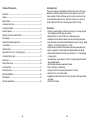
Table of Contents
Introduction
Introduction --------------------------------------------------------------------- 4
Features -------------------------------------------------------------------------- 4
Getting Started ------------------------------------------------------------------ 5
Connecting the AC Line --------------------------------------------------------- 6
Connecting the Motor ----------------------------------------------------------- 8
Modes of Operation ------------------------------------------------------------ 10
Setting Up for Pulse & Direction Mode ---------------------------------------- 11
Microstepping ------------------------------------------------------------------ 12
Selecting Microstepping Resolution -------------------------------------------- 13
Joystick Mode ------------------------------------------------------------------ 14
Oscillator Mode ---------------------------------------------------------------- 15
Speed Control from 0 to 5 Volt Analog Signal --------------------------------- 17
Connecting Digital Inputs ------------------------------------------------------ 18
Enable Input -------------------------------------------------------------------- 19
Setting Phase Current ---------------------------------------------------------- 20
Current Set Table --------------------------------------------------------------- 21
Mounting the Drive ------------------------------------------------------------- 22
Recommended Motors ---------------------------------------------------------- 23
Block Diagram ------------------------------------------------------------------ 23
Technical Specifications -------------------------------------------------------- 24
-3-
Thank you for selecting an Applied Motion Products motor control. We hope our
dedication to performance, quality and economy will make your motion control
project successful. If there’s anything we can do to improve our products or help
you use them better, please call or fax. We’d like to hear from you. Our phone
number is (800) 525-1609 or you can reach us by fax at (831) 761-6544.
Features
• Powerful, precise and efficient mosfet driver providing up to 3.5 amps per phase
and microstepping to 50,800 steps per revolution.
• Reliable, efficient, low noise 40 VDC linear, toroidal power supply.
• Automatic idle current reduction reduces motor and drive heating, saves power.
• Inputs and outputs are optically isolated, differential (sourcing or sinking). Speed
& Enable 5 - 24 VDC, Step & Direction 5 - 12 VDC.
• Digital oscillator provides smooth accel/decel ramps and precise speed control.
• Easy to configure with on-board switches and potentiometers for all settings.
• Oscillator Mode operates from internal pots, external pots, 0 - 5 V analog signal,
or analog joystick.
• Two speed ranges, can be selected “on the fly” by a digital signal with automatic
ramping between speeds.
• Tach Out signal allows easy measurement of speed.
• Built-in self test for troubleshooting.
• Accepts 110 or 220 volt AC power (factory preset for 110 volts).
• Sturdy 2.25 x 7.8 x 5 inch metal chassis.
• Pluggable screw terminal connectors for motor, AC power and I/O signals makes
wiring easy.
• CE and TUV Compliant
-4-
Getting Started
Connecting the AC Line
To use your PDO 3540 motor control, you will need the following:
✔ a power cable (line cord)
✔ a compatible step motor
✔ a small flat blade screwdriver for tightening the connectors - an Applied Motion
Products screwdriver suitable for this purpose is included with your drive.
For pulse & direction mode:
✔ a source of step pulses (usually an indexer is used)
For oscillator mode:
✔ an instrument for measuring motor speed (tachometer, freq. counter or o-scope)
For joystick mode:
✔ an analog joystick (see page 25 for recommended joystick)
The PDO 3540 is set for 110 VAC operation at the factory. If you use 110 VAC
power, all you need to do is install a power cord and plug it in. If you plan to use
220 VAC power, follow the instructions below. Note: If you plan to hard wire the
PDO 3540 to AC power, consult a qualified electrician and observe all building and
electrical codes. AC power can be dangerous.
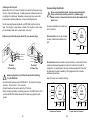
The sketch below shows where to find the important connection and adjustment
points. Please examine it now. All mating connectors are included.
Dip Switches
oscillator mode
current setting
microstep resolution
idle current
220 VAC Instructions
In order to use 220 volts, you’ll need to change a switch setting inside the case.
• Remove all mating connectors from the drive.
• Set the drive on it’s widest side, so that you can read PDO 3540 Step Motor
Driver properly.
• Remove the four (4) phillips head screws that mount the chassis sheet metal to
the chassis heat sink. See page 17 for a mechanical outline of the drive.
• The 110/220 switch is located near the position of the AC power connector, next
to the toroidal transformer (see sketch below).
• For 220 VAC operation slide the switch towards the bottom of the drive, or
towards the transformer end of the drive. The position of the switch is labeled on
the PC board also, “230” being for 200-240 VAC operation, and “115” for 100-120
VAC operation.
• Replace the fuse next to the switch with the 220 VAC fuse that came with the
drive. See technical specifications on page 25 to order more fuses.
• Replace the drive’s cover and assembly screws.
PC Board
POWER
LOW SPEED
oscillator speed,
accel & decel
BB+
AA+
110/220 VAC
Switch
CN1
Fuse
AC Power
Connector
115
*Always use the blue & white
Applied Motion screwdriver with
this connector. Larger
screwdrivers may remove the
plastic dimples that prevent the
screws from falling out.
230
230
AC
POWER
AC Power Connector
CN1
Trim Pots
Switch set for 110 VAC
-5-
SW1
ACCEL
HIGH SPEED
115
1 2 3 4 5 6 7 8
OSC BYPASS
SELF TEST
1 2 3 4 5 6
step & direction
enable
speed
tachometer out
ext potentiometer
0.1
0.2
0.4
0.8
1.6
(BASE = 0.4 A)
CURRENT
Connector*
Do not attempt to change the 110/220 volt switch setting until
power has been removed from the drive for at least five minutes.
SW1
Motor Connector
JOYSTICK
EXT SPEED
50% IDLE
STEPS/REV
MOTOR
Power LED
PDO 3540
Step Motor Driver
DIR+
DIR–
STEP+
STEP–
EN+
EN–
SPEED+
SPEEDTACH+
TACH–
CW
WPR
CCW
!
Switch set for 220 VAC
-6-
Installing an AC Line Cord
Remove about 5 mm (3/16 inces) of insulation from each of the three wires of your
line cord. (That’s right, three wires. For safety, always use a three wire power cord
on anything with a metal case). Depending on where you got your power cord, it
may have black, white and green wires, or brown, white and green wires.
The AC power plug that was shipped with your PDO 3540 might be one of two
types. The “old style” is shown below, on the left. The “new style” , which comes
with an insulating rubber boot, is shown below, on the right.
Connecting the Motor
Secure any unused motor leads, insulate exposed conductors.
Never connect motor leads to ground or to a power supply.
Never connect or disconnect the motor to the driver when the AC
power is on.
!
You must now decide how to connect your
motor to the drive.
A+
Make sure you follow the proper sketch for you connector style.
Four lead motors can only be connected
one way. Please follow the sketch at the
right.
Red
4
lead
motor
A–
Blue
Yellow
B+
White
B–
green
o
whit e r blue
o
black r brow
To Earth Ground
To Neutral
n
To Line (Hot)
"Old Style"
AC Power Plug
!
To Neutral
green
white
To Line (Hot)
black
To Earth Ground
"New Style"
AC Power Plug
Always unplug the line cord from the wall before attaching
it to the PDO 3540.
•Connect the black or brown wire to the PDO 3540 “L” terminal of the AC power
connector. That is the line, or “hot” connection.
•Connect the white or blue wire to neutral, the “N” terminal.
•Finally, and most importantly, connect the green wire to the “GND” terminal. That
connects the PDO 3540 metal enclosure and DC power supply ground to earth
ground.
4 Leads
Six lead motors can be connected in series or center tap. In series mode, motors
produce more torque at low speeds, but cannot run as fast as in the center tap
configuration. In series operation, the motor should be operated at 30% less than
the rated current to prevent overheating. Wiring diagrams for both connection
methods are shown below.
Note: NC means not connected to anything.
A–
NC
A+
Grn/Wht
A– Grn/Wht
6
lead
motor
White
Green
A+
NC
Red
Black
B–
NC
Red/
Wht
Green
Red
Black
B–
B+
B+
6 Leads Series Connected
-7-
6
lead
motor
White
6 Leads Center Tap Connected
-8-
Red/
Wht
NC
Black
Red
B+
Red/
Wht
Yellow
Yel/
Wht B–
Black
Red
Yel/
B+ Wht
8 Leads Series Connected
Yel
low
Red/Wht B–
8 Leads Parallel Connected
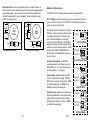
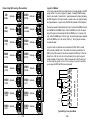
Pulse & Direction Mode - the PDO 3540
receives step pulses from an indexer such as the
Applied Motion Si-1 or Si-100. Steps/revolution
are set by switches 3 - 6 (see page 13).
Joystick mode - speed and direction are determined by an external analog voltage. STEP and
DIR inputs can be used for limit switches. SPEED
input selects speed range. LO SPEED and HI
SPEED pots adjust the 2 speed ranges.
Oscillator mode - speed can be controlled by onboard potentiometers and/or by an external analog
voltage. STEP input starts and stops the motor.
DIR input controls direction of rotation. SPEED
input selects the speed range.
SELF TEST
1
To activate the self test, slide switch #1 toward the
TEST label. The drive will slowly rotate the motor,
1/2 revolution forward, then 1/2 revolution backward. The pattern repeats until you slide the
switch away from the TEST label. The PDO 3540
always uses half step mode during the self test, no
matter how you set the steps/rev switches. The self
test ignores the STEP and DIRECTION inputs
while operating. The ENABLE input continues to
function normally.
Self Test Mode
OSC BYPASS
SELF TEST
1 2
Org/
Wht
A–
8
lead
motor
Pulse & Direction Mode
JOYSTICK
8
Blk/Wht
Orange
Blk/Wht
8
lead
motor
Org/Wht
A–
A+
Self Test Mode is used for trouble shooting. If you are unsure about the motor or
signal connections to the drive, or if the PDO 3540 isn’t responding to your step
pulses, you can turn on the self test.
OSC BYPASS
1 2
Orange
The PDO 3540 has four modes of operation, selected by three dip switches.
SELF TEST
Joystick Mode
JOYSTICK
8
A+
Modes of Operation
OSC BYPASS
1 2
Eight lead motors can also be connected in two ways: series and parallel. As
with six lead motors, series operation gives you more torque at low speeds and less
torque at high speeds. In series operation, the motor should be operated at 30%
less than the rated current to prevent overheating. The wiring diagrams for eight
lead motors are shown below.
SELF TEST
Oscillator Mode
-9-
-10-
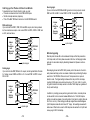
Setting up for Pulse & Direction Mode
To operate the drive in Pulse & Direction mode, you must:
✔ Connect an indexer/controller to the STEP and DIR inputs.
✔ Set the microstep resolution (steps/rev).
✔ Turn off the SELF TEST switch and turn on the OSC BYPASS switch.
Differential Logic
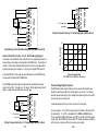
If your controller has STEP+, STEP-, DIR+ and DIR- outputs, which many indexers
do, the connections are simple. Just connect STEP+ to STEP+, STEP- to STEP- and
so forth, as shown below.
Indexer
or
Controller
with
Differential
Outputs
DIR+
DIR+
DIR-
DIR-
STEP+
STEP+
STEP-
STEP-
ENABLE+
ENABLE+
ENABLE-
ENABLE-
Indexer
or
Controller
with
Sinking
Outputs
DIR
DIRSTEP+
STEP
STEPENABLE+
ENABLE-
ENABLE-
= optional signal
-11-
Indexer
or
Controller
with
Sourcing
Outputs
DIR+
DIR-
STEP
STEP+
STEP-
ENABLE
ENABLE+
GROUND
ENABLE-
PDO 3540
Drive
PDO 3540
Drive
Microstepping
Most step motor drives offer a choice between full step and half step resolutions.
In full step mode, both motor phases are used all the time. Half stepping divides
each step into two smaller steps by alternating between both phases on and one
phase on.
Sinking Logic
If your controller has STEP, DIR and +5V outputs, like the Applied Motion Products
Si-1 indexer, connect STEP+ and DIR+ to +5V. Connect STEP- to STEP. Connect
DIR- to DIR.
DIR+
DIR
= optional signal
= optional signal
+5V OUT
Sourcing Logic
If your controller has STEP, DIR and GND (ground or common) outputs, connect
STEP- and DIR- to GND. Connect STEP+ to STEP. Connect DIR+ to DIR.
PDO 3540
Drive
Microstepping drives like the PDO 3540 precisely control the amount of current in
each phase at each step position as a means of electronically subdividing the steps
even further. The PDO 3540 offers a choice of 16 step resolutions in pulse &
direction mode. The highest setting divides each full step into 254 microsteps,
providing 50,800 steps per revolution when using a 1.8° motor. Note: In oscillator/joystick mode the microstep resolution is fixed at 12800 steps/rev, regardless of
the dip switch settings.
In addition to providing precise positioning and smooth motion, microstep drives
can be used for motion conversion between different units. The 25,400 step/rev
setting is provded as a means of converting motion from metric to english (there are
25.4 mm in an inch). Other settings provide step angles that are decimal degrees
(36,000 steps/rev makes the motor take 0.01° steps). Some settings are used with
lead screws. When the drive is set to 2000 steps/rev and used with a 0.2 pitch lead
screw, you get 0.0001 inches/step.
-12-
(1/10)
5000
(1/25)
STEPS/REV
STEPS/REV
25000
(1/125)
25400
(1/127)
25600
(1/128)
3 4 5 6
(1 arc min)
STEPS/REV
3 4 5 6
21600
STEPS/REV
STEPS/REV
3 4 5 6
(1/100)
STEPS/REV
3 4 5 6
2000
STEPS/REV
20000
Joystick Mode
STEPS/REV
3 4 5 6
(1/5)
3 4 5 6
1000
3 4 5 6
(HALF)
STEPS/REV
3 4 5 6
400
STEPS/REV
3 4 5 6
200
(FULL)
3 4 5 6
Selecting Microstep Resolution
In this mode, speed and direction are determined by the voltage applied to the WPR
(wiper) terminal. 2.5 volts is “stopped” (no speed). Increasing the WPR voltage
toward 5 volts results in forward motion: speed increases with voltage. Decreasing
the WPR voltage from 2.5 toward 0 results in reverse motion, with speed increasing
as voltage decreases. In joystick mode, the PDO 3540 operates at 12800 steps/rev.
The maximum speed is determined by two things: the state of the SPEED input and
the HI SPEED and LO SPEED trimpots. When the SPEED input is ON, the speed
range of the joystick can be adjusted with the LO SPEED pot, up to 5 rev/sec (300
rpm). When the SPEED input is OFF (or open), the joystick speed range is adjusted
with the HI SPEED pot, up to 25 rev/sec (1500 rpm). Turning the pots clockwise
increases the speed.
In joystick mode, limit switches can be connected to the PDO 3540 to prevent
motion outside of defined limits. The forward limit should be connected to the
STEP input and the reverse limit should be connected to the DIR input. When the
forward limit is ON, the motor will not move forward (that is, when the joystick
voltage is between 2.5 and 5 volts). When the reverse limit is ON, the motor will
not move when the joystick is in the 0 to 2.5 volt range. If you don’t need limits,
you can leave the STEP and DIR inputs unconnected.
STEP+
STEPS/REV
o
(.01 )
STEPS/REV
+
5-12
VDC
SUPPLY
-
SPEED+
fwd limit switch
STEPDIR-
(1/64)
STEPS/REV
50000
(1/250)
STEPS/REV
3 4 5 6
12800
3 4 5 6
rev limit switch
SPEEDjoystick "fire" button
50800
(1/254)
-13-
STEPS/REV
3 4 5 6
o
(.02 )
STEPS/REV
3 4 5 6
5kΩ
joystick
18000
CW
fwd
PDO 3540
(1/50)
36000
3 4 5 6
10000
3 4 5 6
DIR+
WPR
rev
CCW
Typical Wiring for Joystick Mode
-14-
speed (rev/sec)
There are two speed ranges in oscillator mode. One is the low speed range, which
is activated when the SPEED input is on. The low speed can be set from 0 to 5 rev/
sec (0 - 300 rpm) by adjusting the LO SPEED pot. Turning the pot clockwise
increases the speed.
25
20
15
10
5
0
-5
-10
-15
-20
-25
0
The high speed setting is used when the SPEED input is off, or open. If switch #7
is toward the words EXT SPEED, then the high speed is proportional to the voltage
applied to the WPR terminal, and is trimmed by the HI SPEED pot. You can
connect an external 1K - 5K pot to the WPR, CW and CCW terminals, or you can
apply a 0 to 5 volt analog signal to the WPR terminal (ground your analog signal to
the CCW terminal). The high speed range is 0 - 25 rev/sec (0 - 1500 rpm). You can
reduce the range by turning down the HI SPEED pot. For example, if you want the
motor to go 750 rpm when the external pot is on maximum, turn the HI SPEED pot
down about half way.
1
2
3
volts
4
5
volts
Speed vs. Input Voltage
Joystick Mode, SPEED input off (open)
HI SPEED pot at maximum
When switch #7 is away from the EXT SPEED label, the high speed is set by the HI
SPEED pot and the WPR input does nothing.
!
Never apply more than 5 volts DC or less than 0 volts to the
WPR pin.
Oscillator Mode
In oscillator mode, the PDO 3540 uses the direction set by the DIR input. Off, or
open, gives clockwise motion, if the motor is wired according to pages 8 and 9.
Motor speed and the function of the STEP input can be determined from the
following table. In oscillator mode, the PDO 3540 operates at 12800 steps/rev.
ON
switches
7&8
joystick
ext speed
speed set
by
7 8
SPEED
input
when STEP
goes ON
when STEP
goes OFF
accel to speed
instant stop
accel to speed
instant stop
accel to speed
decel to stop
accel to speed
decel to stop
ON
joystick
ext speed
7 8
LO SPEED
OFF/open
joystick
ext speed
joystick
ext speed
7 8
OFF/open
7 8
LO SPEED
HI SPEED
WPR input
trimmed by
In joystick and oscillator modes, the accel/decel rate is set by the
ACCEL pot.
The acceleration range is 1 to 250 rev/sec/sec. Turning the pot clockwise makes the
motor start and stop faster, but if you set it too high the motor may run out of
torque and stall.
In nearly all cases, the accel/decel rate you set is respected by the PDO 3540. For
example, if you switch the SPEED input while the motor is moving, the drive will
change speeds smoothly. If you are operating in EXT SPEED mode and make a
sudden change in the voltage to the WPR terminal, the drive accelerates (or decelerates) to the new speed smoothly, according to the accel pot setting.
The only time the drive makes an instant change is when the SPEED input is on and
the STEP input goes off. That is done so that you can stop instantly (and exactly)
from a low speed.
HI SPEED
-15-
-16-
STEPDIR-
direction switch
SPEED-
speed switch (closed=lo speed)
CW
0 - 5V speed signal
WPR
signal return
CCW
Wiring for Speed Control by 0 - 5 Volt Analog Signal (Unidirectional)
CW
cw
5kΩ
pot
WPR
ccw
25
Speed Control from a 0 to 5 Volt Analog Signal
In oscillator mode, the PDO 3540 can rotate the motor at a speed proportional to an
analog voltage. The voltage must be applied to the WPR terminal. The direction of
rotation is controlled by the digital DIR input and the motor can be stopped either
by setting the analog input voltage to 0 or by turning the digital STEP signal off.
To use the PDO 3540 in this mode, set switch #8 away from the JOYSTICK label,
and set switch #7 toward the EXT SPEED label.
The HI SPEED pot sets the maximum speed (the motor speed when the analog
signal is at 5 volt DC). The range is 0 - 25 rev/sec. Wiring diagrams and a plot of
speed v. voltage are shown below and on the next page.
STEP+
DIR+
STEPDIR-
PDO 3540
run/stop switch
(closed=run)
speed (rev/sec)
CCW
Typical Wiring for Oscillator Mode Using External Speed Control Pot
+
5-12
VDC
SUPPLY
-
PDO 3540
run/stop switch
(closed=run)
STEP-
PDO 3540
+
5-12
VDC
SUPPLY
-
STEP+
STEP+
DIR+
SPEED+
20
15
10
5
0
0
1
2
3
4
5
Speed vs Input Voltage
EXT SPEED mode, HI SPEED pot at maximum
Connecting Digital Inputs
The PDO 3540 contains optical isolation circuitry to prevent the electrical noise
inherent in switching amplifiers from interfering with your circuits. This arrangement also allows a wide range of input voltages to be used and gives you the option
of using sinking or sourcing inputs.
A schematic diagram of the input circuit is shown on the next page.
Wiring for Speed Control by 0 - 5 V Analog Signal (with Dir Control)
You must supply 5 - 12 volts DC to supply current to the LEDs on the input side of
the optoisolators. 5 - 24 VDC is acceptable for the SPEED and ENABLE inputs.
You can operate the STEP and DIR inputs at 24 VDC if you add a 1000 ohm resistor
to each input. Most CMOS and open collector TTL devices are directly compatible
with this drive, as are typical PLC and proximity sensor outputs.
-17-
-18-
direction switch
0 - 5V speed signal
signal return
WPR
CCW
Setting Phase Current
STEP+
R
STEP-
Before you turn on the power supply the first time, you need to set the driver for the
proper motor phase current. The rated current is usually printed on the motor label.
The current you set on the PDO 3540 is the peak current, not RMS.
PDO 3540 Input circuit
Tach Output
The Tach Out signal is provided for measuring the motor speed. It generates 100
pulses per revolution, so if you connect a frequency counter, the speed reads out in
revs/second with two decimal places.
!
Do not connect the Tach output to more than 24 VDC.
The current into the Tach+ terminal must not exceed 20 mA.
Enable Input
ENABLE allows the user to turn off the current to the motor by setting this signal to
logic 0. The logic circuitry continues to operate, so the drive “remembers” the step
postion even when the amplifiers are disabled. However, the motor may move
slightly when the current is removed depending on the exact motor and load
characteristics. If you have no need to disable the amplifiers, you don’t
need to connect anything to the ENABLE input.
-19-
1 2 3 4 5
Idle Current Reduction
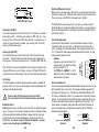
Your drive is equipped with a feature that automatically reduces the motor current by
50% anytime the motor is not moving. This reduces drive heating by about 50%
and lowers motor heating by 75%. This feature can be disabled if desired so that
full current is maintained at all times. This is useful when a high holding torque is
required. To minimize motor and drive heating we highly recommend that you use
the idle current reduction feature unless your application strictly forbids it. Idle
current reduction is enabled by sliding switch #6 toward the 50% IDLE label, as
shown in the sketch below. Sliding the switch away from the 50% IDLE label
disables the reduction feature.
50% IDLE
50% IDLE
Idle Current Reduction
Enabled
6
Note: We refer to an input as being ON when current is flowing through the input.
A signal is OFF when no current is flowing. An input is OFF when COM and the
input terminal are at the same voltage, or when the input is left unconnected (open).
CURRENT
(BASE = 0.4 A)
Sourcing Circuits (PNP)
If your output devices can only source current (some PLC outputs are this way),
connect the “-” terminals to the ground of the DC power supply that powers your
output circuits. Then connect your signals to the “+” terminals (STEP+, DIR+, etc.).
Current Setting Formula
Locate the bank of eight switches. Five of the switches have a value of current
printed next to them, such as 0.2 and 1.6. Each switch controls the amount of
current, in amperes (A), that it’s label indicates. There is always a base current of
0.4 A. To add to that, slide the appropriate switches toward their labels. You may
need your small screwdriver for this.
Example
Suppose you want to set the driver for 2.2
0.1
amps per phase. You need the 0.4 A base
0.2
current plus another 1.8 A.
0.4
2.2 (TOTAL) = 0.4 (BASE) + 1.6 + 0.2
0.8
Slide the 1.6 and 0.2 A switches toward the
1.6
labels as shown in the figure.
6
Sinking Circuits (NPN)
If your output devices sink current, then connect the “+” terminals to your positive
power supply, and the “-” terminals to your signals (i.e. STEP-, DIR-, etc.). If you
are using a TTL circuit to drive the PDO 3540, connect the “+” terminals to your 5
volt bus. No ground connection is needed. If you are using a PLC or proximity
sensor, you’ll need a power supply.
The PDO 3540 drive current is easy to set. If you wish, you can learn a simple
formula for setting current and never need the manual again. Or you can skip to the
table on the next page, find the current setting you want, and set the DIP switches
according to the picture.
Idle Current Reduction
Disabled
-20-
Current Set Table
Mounting the Drive.
AMPS/
PHASE
2.6
AMPS/
PHASE
2.7
AMPS/
PHASE
-21-
3.1
AMPS/
PHASE
3.2
AMPS/
PHASE
3.3
AMPS/
PHASE
3.4
AMPS/
PHASE
3.5
AMPS/
PHASE
1 2 3 4 5
0.1
0.2
0.4
0.8
1.6
0.1
0.2
0.4
0.8
1.6
0.1
0.2
0.4
0.8
1.6
Use for NARROW-SIDE
mounting.
Use for WIDE-SIDE
mounting.
1 2 3 4 5
1 2 3 4 5
0.1
0.2
0.4
0.8
1.6
AMPS/
PHASE
0.1
0.2
0.4
0.8
1.6
1 2 3 4 5
0.1
0.2
0.4
0.8
1.6
3.0
1 2 3 4 5
0.1
0.2
0.4
0.8
1.6
AMPS/
PHASE
0.1
0.2
0.4
0.8
1.6
1 2 3 4 5
2.5
0.1
0.2
0.4
0.8
1.6
2.9
0.1
0.2
0.4
0.8
1.6
1 2 3 4 5
AMPS/
PHASE
0.1
0.2
0.4
0.8
1.6
2.8
AMPS/
PHASE
0.1
0.2
0.4
0.8
1.6
0.1
0.2
0.4
0.8
1.6
1 2 3 4 5
2.4
1 2 3 4 5
AMPS/
PHASE
0.1
0.2
0.4
0.8
1.6
AMPS/
PHASE
1 2 3 4 5
1.9
2.3
1 2 3 4 5
AMPS/
PHASE
0.1
0.2
0.4
0.8
1.6
AMPS/
PHASE
0.1
0.2
0.4
0.8
1.6
1 2 3 4 5
1.8
2.2
1 2 3 4 5
AMPS/
PHASE
0.1
0.2
0.4
0.8
1.6
AMPS/
PHASE
0.1
0.2
0.4
0.8
1.6
1 2 3 4 5
1.7
0.1
0.2
0.4
0.8
1.6
2.1
1 2 3 4 5
AMPS/
PHASE
0.1
0.2
0.4
0.8
1.6
2.0
AMPS/
PHASE
0.1
0.2
0.4
0.8
1.6
1 2 3 4 5
1.6
1 2 3 4 5
AMPS/
PHASE
0.1
0.2
0.4
0.8
1.6
AMPS/
PHASE
1 2 3 4 5
1.1
1.5
1 2 3 4 5
AMPS/
PHASE
0.1
0.2
0.4
0.8
1.6
AMPS/
PHASE
0.1
0.2
0.4
0.8
1.6
1 2 3 4 5
1.0
1.4
1 2 3 4 5
AMPS/
PHASE
0.1
0.2
0.4
0.8
1.6
AMPS/
PHASE
0.1
0.2
0.4
0.8
1.6
1 2 3 4 5
0.9
0.1
0.2
0.4
0.8
1.6
1.3
1 2 3 4 5
AMPS/
PHASE
0.1
0.2
0.4
0.8
1.6
1.2
AMPS/
PHASE
0.1
0.2
0.4
0.8
1.6
1 2 3 4 5
0.8
1 2 3 4 5
AMPS/
PHASE
1 2 3 4 5
0.7
1 2 3 4 5
AMPS/
PHASE
0.1
0.2
0.4
0.8
1.6
1 2 3 4 5
0.6
1 2 3 4 5
AMPS/
PHASE
0.1
0.2
0.4
0.8
1.6
1 2 3 4 5
0.5
1 2 3 4 5
0.4
AMPS/
PHASE
1 2 3 4 5
You can mount your drive on the wide or the narrow side of the chassis.
0.1
0.2
0.4
0.8
1.6
+
DIR DIR
+
P
E
ST PSTE
!
Never use your drive in a space where there is no air flow or
where the ambient temperature exceeds 50 oC (120 oF).
Never put the drive where it can get wet.
Never allow metal particles near the drive.
-22-
Recommended Motors
Motor
Number
5014-842
HT17-068
HT17-071
HT17-075
5023-122
5023-123
5023-124
HT23-394
HT23-397
HT23-400
5034-348
Size
inches
1.38 x 1.38 x 1.57
1.65 x 1.65 x 1.30
1.65 x 1.65 x 1.54
1.65 x 1.65 x 1.85
2.22 x 2.22 x 2.0
2.22 x 2.22 x 3.0
2.22 x 2.22 x 4.0
2.22 x 2.22 x 1.54
2.22 x 2.22 x 2.13
2.22 x 2.22 x 2.99
3.38 x 3.38 x 2.50
Technical Specifications
Winding
Connection
4 lead
parallel
parallel
parallel
parallel
parallel
parallel
parallel
parallel
parallel
parallel
Max Torque
oz-in
19
23
30
40
60
100
150
60
140
180
130
Current
Amps
1.0
1.4
1.7
1.7
2.0
2.5
3.5
2.8
2.8
2.8
3.5
Amplifiers
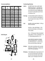
Dual, MOSFET H-bridge, 3 state, pulse width modulated
(PWM) switching at 20 kHz. 0.4 - 3.5 amps/phase output
current, dip switch selectable. 122 watts maximum output
power. Automatic idle current reduction (defeatable) reduces
motor current to 50% of setting after one second. Minimum
motor inductance is 0.8 mH.
Power Supply
Linear, toroidal transformer based for high reliability and low
noise. 100-120 or 200-240 VAC input, switch selectable. 50/
60 Hz. DC voltage at nominal line voltage: 35 VDC full load,
40 VDC no load.
Inputs
Speed, Enable: optically isolated, differential 5 - 24 VDC logic.
2200 ohms internal resistor.
Step, Direction: optically isolated, differential 5 - 12 VDC
logic, 680 ohms internal resistance. (24 VDC with external
1000 ohm resistance).
Block Diagram
fuse
110 or
220 VAC
STEP
DIRECTION
ENABLE
HI/LO SPEED
TACH
Internal
Power
Supply
Optical
Isolation
Microstep
Sequencer
Digital Oscillator
&
Joystick Interface
LO
speed
accel
steps/rev
osc bypass
self test
motor phase B
MOSFET
3 State
PWM
Power
Amplifier
joystick
ext speed
HI
speed
In pulse & direction mode, motor steps on rising edge of
STEP+ input (falling edge of STEP-). 0.25 msec minimum
pulse, 2 MHz maximum step rate. 1 msec minimum set up
time, 50 msec minimum hold time for direction signal.
current
0.4 to 3.5
A/phase
motor phase A
EXT
SPEED
INPUT
Wiper: 0 - 5 VDC analog signal. Maximum recommended pot/
joystick impedance: 1K - 5K ohms. Joystick dead zone: +/- 80
mV. Potentiometer/analog signal dead zone: 40 mV.
power LED
50% idle
-23-
Tach Output
Optically isolated, uncommitted (open collector, open emitter)
photo transistor. 30 VDC, 20 mA max. 100 pulses per motor
revolution, 50% duty cycle (square wave).
Microstepping
16 switch selectable resolutions. Steps per revolution with 1.8°
motor: 200, 400, 1000, 2000, 5000, 10000, 12800, 18000,
20000, 21600, 25000, 25400, 25600, 36000, 50000, 50800.
Waveform: pure sine. 12800 steps/rev in OSC/JOY mode.
-24-
Technical Specifications (cont’d.)
Mechanical Outline
Recommended Maurey Instrument Corp., Chicago, IL (773) 581-4555
Joystick
JS31462S5T3 (2 axis) or SAJ2515-F-502 (1 axis)
European style, pluggable screw termminal blocks.
Motor: 4 position. Wire size: AWG 12 - 26
Signal Input/Output: 13 position. Wire size: AWG 16 - 28
AC Input: 3 position. Wire size: AWG 12 - 20
CE Marks
Complies with EN55011a, EN50082-1(1996), EN50178(1997)
Fuses
Wickman TR-5 style. Order from Digikey (1-800-DIGIKEY)
110V: P/N WK4053BK-ND (1.6 A UL)
220V: P/N WK4046BK-ND (0.8 A UL)
-25-
1 2 3 4 5 6 7 8
OSC BYPASS
SELF TEST
1 2 3 4 5 6
(BASE = 0.4 A)
0.1
0.2
0.4
0.8
1.6
STEPS/REV
POWER
ACCEL
HIGH SPEED
LOW SPEED
MOTOR
Connectors
7.80"
JOYSTICK
EXT SPEED
50% IDLE
0.200"
(x6)
BB+
AA+
AC
POWER
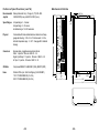
Constructed with black anodized aluminum heat sink and heavy
gauge steel housing. 2.25 x 5.4 x 7.8 inches overall. 4.0 lbs.
Ambient temperature range: 0 - 50 oC. See page 26 for detailed
drawing.
Step Motor Driver
Physical
DIR+
DIR–
STEP+
STEP–
EN+
EN–
SPEED+
SPEEDTACH+
TACH–
CW
WPR
CCW
CURRENT
LO speed range: 0 - 5 rev/sec
HI speed range: 0 - 25 rev/sec
Accel/decel range: 1 to 250 rev/sec/sec
PDO 3540
Speed Ranges
0.200" (x6)
1.125"
0.750"
2.25"
0.750"
5.00"
5.40"
-26-
5/10/99
Notes
Applied Motion Products, Inc.
-27-
404 Westridge Drive Watsonville, CA 95076
(800) 525-1609
Tel (831) 761-6555
Fax (831) 761-6544
http://www.applied-motion.com
Copyright 1999
-28-