1
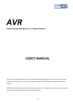
Sold By: Servo Systems Co. • 53 Green Pond Road, Suite #2 • Rockaway, NJ 07866
(973) 335-1007 • Toll Free: (800) 922-1103 • Fax: (973) 335-1661 • www.servosystems.com
User’s Manual
Si5580
Programmable Step Motor Driver
IN 1
IN 2
IN 3
IN 4
JOG CW POWER
JOG CCW
IN/JOG COM TEMP
IN/JOG COM SHORT
PC/MMI
LIMITS
CW+
CWCCW+
CCWOUT 1+
OUT 1OUT 2+
OUT 2OUT 3+
OUT 3FAULT+
FAULT-
STOP
MOTOR
90V pk
B–
B+
A–
A+
Si5580
Step Motor Driver
AC
POWER
G
920-0036B 7/7/10
N
L
motors • drives • controls
Contents
Introduction
3
Features
3
Getting Started
4
Connecting the AC Line
5
Installing an AC Line Cord
7
Connecting the Motor
8
Connecting to the PC
10
Jogging
11
Limit Switches
11
Wiring a Mechanical Limit Switch 12
Wiring a Limit Sensor
12
Wiring Inputs
13
Wiring Outputs
15
Faults and Alarms
16
Using the Fault Output
16
Alarm Codes
17
Microstepping
17
Mounting the Drive
18
Mounting the Optional MMI
18
Mechanical Outline
20
Mechanical Outline - Optional MMI 21
Technical Specifications
22
Recommended Motors
23
Block Diagram
23
-2-
Introduction
Thank you for selecting an Applied Motion Products motor control. We hope our dedication to performance, quality and economy will make your motion control project successful. If there’s anything
we can do to improve our products or help you use them better, please call or fax. We’d like to hear
from you. Our phone number is (800) 525-1609 or you can reach us by fax at (831) 761–6544.
Features
• Powerful, precise and efficient MOSFET driver providing up to 5.5 amps per phase and microstepping to 50,800 steps per revolution.
• Reliable, efficient, low noise 80 VDC linear, toroidal power supply.
• Powerful, flexible, easy to use indexer.
• Connects by a simple cable to your PC for programming (cable included).
• Microsoft WindowsTM-based software for easy set up and programming.
• Eight inputs for interacting with the user and other equipment.
• Three outputs for coordinating external equipment.
• Accepts 110 or 220 volts AC power (factory preset for 110 volts).
• Sturdy 3 x 8 x 5.3 inch metal case with integral heat sink.
Mounting brackets included.
• I/O is optically isolated, 5-24 V, sinking or sourcing signals. PC/MMI port is RS-
232.
• Pluggable screw terminal connectors for I/O, motor and AC power
(all mating connectors included).
• Three LEDs indicate power, drive and indexer status.
• Overcurrent (short circuit) and over temperature protection.
• Optional man machine interface (MMI) allows operator to enter distances, speeds, cycle counts and more.
• CE and TUV compliant
-3-
Getting Started
To use your Si5580 motor control, you will need the following:
• a power cable (line cord)
• a compatible step motor
• a small flat blade screwdriver for tightening the connectors - an Applied Motion Products screwdriver suitable for this purpose is included with your drive.
• a personal computer running Windows 3.2, 95, 98, NT, W2K, XP, Vista or Vista64, with a 9 pin
serial port (486 or better with 8 MB RAM recommended)
• the Si ProgrammerTM software that came with your Si5580
• the programming cable and adapter that came with your Si5580
• Si ProgrammerTM software manual
The sketch below shows where to find the important connection and adjustment points. Please
examine it now.
All mating connectors are included.
I/O Connector
IN 1
IN 2
IN 3
IN 4
JOG CW POWER
JOG CCW
IN/JOG COM TEMP
IN/JOG COM SHORT
inputs 1-4
jog cw, ccw
I/O Connector
power
overtemp
overcurrent
LIMITS
CW+
CWCCW+
CCWOUT 1+
OUT 1OUT 2+
OUT 2OUT 3+
OUT 3FAULT+
FAULT-
LEDs
I/O Connector
outputs 1-3
fault output
RS232 connector
PC/MMI
cw, ccw limits
STOP
pc
mmi
STOP button
MOTOR
90V pk
B–
B+
A–
A+
Motor connector
Si5580
Step Motor Driver
G
AC
POWER
Always use the blue & white
Applied Motion screwdriver
with the above I/O connectors.
Larger screwdrivers may remove
the plastic dimples that prevent
the screws from falling out.
N
L
-4-
AC power connector
Connecting the AC Line
The Si5580 is set for 110 VAC operation at the factory. If you use 110 VAC power, all you need to do
is install a power cord and plug it in (skip to Installing an AC Line Cord). If you plan to use 220
VAC power, follow the instructions below.
Note: If you plan to hard wire the Si5580 to AC power, consult a qualified electrician and observe all
building and electrical codes. AC power can be dangerous.
220 VAC Instructions
In order to use 220 volts, you’ll need to set the 110/220 VAC switch to the correct position and install
the correct fuse.
1) Remove all mating connectors from the drive.
2) Set the drive on its side, with the aluminum heat sink fins up.
3) With a medium-sized phillips screwdriver, remove the eight screws at the perimeter of the case and
the three screws that connect the heat sink to the internal heat bar, keeping track of which screws
go where. See the diagram below.
2 screws
3 screws on
top (longest
length)
2 screws
2 screws
(shortest
length)
2 screws (medium length)
Note: Do not remove the 1/4-20 Allen head screw that connects the heat sink to the internal transformer.
4) Separate the heat sink assembly from the cover and note how the wires are routed to the PC board.
There are labels on the PC board to assist you.
5) Disconnect the two sets of wires connecting the heat sink/transformer assembly to the chassis/PC
board. The 110/220 VAC SWITCH is located on the PC board, near the AC power connector. See
diagram on page 6.
-5-
PC BOARD
110/220 VAC
SWITCH
AC POWER
CONNECTOR
CN3
CN3
220V
220V
C23
C23
F1
CN1
110V
F1
110V
Switch set for 220 VAC
CN1
FUSE
Switch set for 110 VAC
6) Remove the 110 VAC fuse and install the 220 VAC fuse that came with your drive. There is a label
inside the drive that gives the correct fuse values.
7) Place the voltage selector switch in the correct position according to the labels on the printed
circuit board near the switch. See the diagram above.
8) Re-assemble the chassis/PC board assembly to the heat sink/transformer assembly by following
steps 4 & 5 in reverse. Again, pay close attention to the correct orientation of the two sets of wires
connecting these assemblies.
9) Install and tighten the screws removed in step 3. Use the correct length screw according to the
hole location.
You are done converting your drive to 220 VAC operation and
are now ready to install the AC line cord.
-6-
Installing an AC Line Cord
Remove about 5 mm (3/16 inches) of insulation from each of the three wires of your line cord. (That’s
right, three wires. For safety, always use a three wire power cord on anything with a metal case.)
Depending on where you got your power cord, it may have black, white and green wires or brown/
blue/green.
The AC power plug that was shipped with your Si5580 might be one of two types. The “old style” is
shown in the diagram below, on the left. The “new style”, shown on the right, comes with an insulating rubber boot.
Make sure you follow the proper sketch for your connector style.
green
o
whit e r blue
o
r brow
k
c
a
bl
n
To Earth Ground
To Neutral
To Line (Hot)
To Earth Ground
To Neutral
To Line (Hot)
"Old Style"
AC Power Plug
green
white
black
"New Style"
AC Power Plug
Always unplug the line cord from the wall before attaching it
to the Si5580
•Connect the black or brown wire to the Si5580 “L” terminal of the AC power connector. That is the
line, or “hot” connection.
•Connect the white or blue wire to neutral. That’s the “N” terminal.
•Finally, and most importantly, connect the green wire to the GND terminal. That connects the
Si5580 metal enclosure and DC power supply ground to earth ground.
-7-
Connecting the Motor
Never connect the motor to the driver when the AC power is on.
Secure any unused motor leads.
Never disconnect the motor while the AC power is on.
Never connect motor leads to ground or to a power supply.
You must now decide how to connect your motor to the
drive.
A+
Four lead motors can only be connected one way.
Please follow the sketch at the right.
A–
Red
4
lead
motor
Blue
Yellow
B+
White
B–
4 Leads
Six lead motors can be connected in series or center tap. In series mode, motors produce more
torque at low speeds, but cannot run as fast as in the center tap configuration. In series operation, the
motor should be operated at 30% less than the rated current to prevent overheating. Wiring diagrams
for both connection methods are shown below.
Note: NC means not connected to anything.
A–
NC
A+
Grn/Wht
A– Grn/Wht
6
lead
motor
White
Green
A+
NC
Red
B–
Black
NC
Red/
Wht
6
lead
motor
White
Green
Red
B–
B+
6 Leads Series Connected
Black
B+
Red/
Wht
NC
6 Leads Center Tap Connected
-8-
Eight lead motors can also be connected in two ways: series and parallel. As with six lead motors,
series operation gives you more torque at low speeds and less torque at high speeds. In series operation, the motor should be operated at 30% less than the rated current to prevent overheating. The
wiring diagrams for eight lead motors are shown below.
A+
Orange
Blk/Wht
Org/
Wht
A–
Black
Red
B+
Red/
Wht
Orange
Blk/Wht
8
lead
motor
Org/Wht
A–
A+
Yellow
Yel/
Wht B–
8
lead
motor
Black
Red
Yel/
B+ Wht
8 Leads Series Connected
Yel
low
Red/Wht B–
8 Leads Parallel Connected
-9-
Connecting to the PC
•Locate your computer within 6 feet of the Si5580.
•Your Si5580 was shipped with a black adapter plug. It has a telephone style jack at one end and a
larger 9 pin connector at the other. Plug the large end into the COM1 serial port of your PC. Secure
the adapter with the screws on the sides. If the COM1 port on your PC is already used by something
else, you may use the COM2 port for the Si5580. On some PCs, COM2 will have a 25 pin connector
that does not fit the black adapter plug. If this is the case, and you must use COM2, you may have to
purchase a 25 to 9 pin serial adapter at your local computer store.
•Your Si5580 was also shipped with a 7 foot telephone line cord. Plug one end into the adapter we
just attached to your PC, and the other end into the PC/MMI jack on your Si5580.
Never connect the Si5580 to a telephone circuit. It uses the same connectors and cords as telephones and modems, but the voltages are not compatible.
Programming Note: Always apply power to the Si5580 after the Si ProgrammerTM software is running
on your PC.
-10-
Jogging
Two of the Si5580 input terminals are provided for jogging the motor. The inputs are labeled “JOG
CW” and “JOG CCW”. Activating one of the inputs commands the drive to move the motor at a predesignated speed until the contact is opened. A relay or mechanical switch can be used to activate
the jog inputs. 5-24 volt circuitry can be used. The schematic diagram of the input circuit is shown
below.
If you’re using a switch or relay, wire one end to the JOG input and the other to the power supply
negative (-) terminal. Then connect the COM input to the power supply positive (+) terminals.
inside Si5580
COM
+
5-24
VDC
SUPPLY
-
2200
JOG CW
2200
JOG CCW
Limit Switches
The Si5580 has two limit switch inputs, LIMIT CW and LIMIT CCW. By connecting these inputs to
switches or sensors that are triggered by the motion of the motor or load, you can force the Si5580
to operate within certain limits. This is useful if a program error could cause damage to your system
from the motor traveling too far.
As the limit inputs of the Si5580 are optically isolated, you can choose a voltage between 5-24 Vdc
to apply to your limit circuitry. This allows you to have long wires on limit sensors with less risk of
intoducing noise to the Si5580 (choose 12-24 Vdc for best noist immunity). The power light will blink
if a limit switch is activated. The schematic diagram of the limit switch input circuit is shown below.
inside Si5580
+5V
+5V
10K
Si5580
Controller
Chip
3
CW LIMIT+
CW LIMIT–
CCW LIMIT+
CCW LIMIT–
4
1
2
2200
-11-
Wiring a Mechanical Limit Switch
You can use normally open or normally closed limit switches. Either way, wire them as shown here.
CW LIMIT+
CCW LIMIT+
+
5-24
VDC
SUPPLY
-
CW LIMIT-
Si5580
CCW LIMIT-
Wiring a Limit Sensor
Some systems use active limit sensors that produce a voltage output rather than a switch or relay
closure. These devices must be wired differently than switches.
If your sensor has an open collector output or a sinking output, wire it like this:
CW LIMIT+
+
DC
Power
Supply
–
+
Limit
Sensor
–
output
Si5580
CW LIMIT-
Wiring for Sinking or Open Collector Output
If the sensor output goes low at the limit, select the option “closed”. If the output is open, or high
voltage, choose “open”.
Other sensors have sourcing outputs. That means that current can flow out of the sensor output, but
not into it. In that case, wire the sensor this way:
+
DC
Power
Supply
–
+
Proximity
Sensor
–
output
LIMIT+
Si5580
LIMIT-
Wiring for Sourcing Output
If the sensor output goes high at the limit, choose the program option “closed”. if the output is low at
the limit, select “open”.
-12-
Wiring Inputs
The Si5580 input circuits can be used with
sourcing or sinking signals, 5 to 24 volts. This
allows connection to TTL circuits, PLCs, relays
and mechanical switches. Because the input
circuits are isolated, they require a source of
power. If you are connecting to a TTL circuit
or to a PLC, you should be able to get power
from the PLC or TTL power supply. If you are
using relays or mechanical switches, you will
need a 5-24 power supply. This also applies if
you are connecting the Si5580 inputs to another
Si product from Applied Motion, like the Si-1
and Si-100 indexers, or the Si3540 and 7080i
indexer-drives.
inside Si5580
COM
COM
2200
IN1
2200
IN2
2200
IN3
2200
IN4
2200
JOG CW
2200
JOG CCW
Note: If current is flowing into or out of an Si5580 input, the logic state of that input is low. If no
current is flowing, or the input is not connected, the logic state is high.
The diagrams on the following pages show how to connect Si5580 inputs to various devices.
The maximum voltage that can be applied to an input terminal is 24 volts
DC. Never apply AC voltage to an input terminal. Maximum current is 20
mA per input.
5-24
VDC
Power
Supply
+
COM
Si5580
switch or relay
(closed=logic low)
IN
-
Connecting an Input to a Switch or Relay
Use normally open momentary switch to trigger Si5580 using Wait Input instruction.
Use single throw switch for parameter selection using If Input instruction.
Use normally open momentary switch for jogging.
-13-
IN/JOG COM
MOTION+
IN
5-24
VDC
Power
Supply
Si5580
SI-1 indexer
+
MOTION–
-
+
Si5580
Si3540, 7080i
or MC8400
Connecting an Input to the Si-1 Motion Output
(Set Si-1 motion signal to “in position”. Si-1 will trigger Si5580 at end of each move).
COM
OUT+
IN
OUT–
-
5-24
VDC
Power
Supply
Connecting a 3540i, Si3540, 7080i or MC8400
(When output closes, Si5580 input goes low).
5-24 +
VDC
Power
Supply -
+
NPN
Proximity
Sensor
–
COM
output
IN
Si5580
Connecting an NPN Type Proximity Sensor to an Si5580 input
(When prox sensor activates, Si5580 input goes low).
5-24 +
VDC
Power
Supply -
+
PNP
Proximity
Sensor
–
output
IN
COM
Si5580
Connecting a PNP Type Proximity Sensor to an Si5580 input
(When prox sensor activates, Si5580 input goes low).
-14-
Wiring Outputs
Before we discuss the output conditions, we need to talk about the circuitry. All three Si5580 outputs
are optically isolated. That means that there is no electrical connection between the indexer-drive and
the output terminals. The signal is transmitted to the output as light. What you “see” is a transistor
(NPN type) that closes, or conducts current, when the output is “low”. When the output is high, the
transistor is open.
Note: At power-up, the Si5580 sets all three programmable outputs high (open circuit).
The maximum voltage between any pair of + and - output terminals is 24
volts DC. Never connect AC voltages to the Si5580 output terminals. Maximum current is 100 mA per output.
+5V
inside Si5580
330W
OUT1+
OUT1–
Si5580
Controller Chip
Schematic Diagram of Si5580 Output Circuit
Since there is no electrical connection to the Si5580, you must provide the source of current and
voltage, typically from a power supply. You must also limit the current to less than 100 mA so that the
output transistor is not damaged. You would normally use a resistor for this, but some loads (such as
PLC inputs) limit the current automatically.
The diagram below shows how to connect an Si5580 output to an optically isolated PLC input.
12-24 VDC
Power Supply
+
–
OUTPUT+
COMMON
OUTPUT-
INPUT
Si5580
-15-
PLC
Faults and Alarms
The Si5580 provides protection against motor short circuits and excessive drive temperature. The
drive also provides an alarm if a limit switch is reached.
If the TEMP light is on the Si5580 has detected a thermal problem and shut down the amplifiers. The
first thing you should do is to unplug the drive from the power source. If the heat sink is very hot, the
drive has probably overheated - please use caution, do not directly touch heat sink to avoid a possible
burn. Usually this means you need more air flow around the drive.
If the SHORT light is on the Si5580 has detected a short circuit and has shut down the amplifiers.
Unplug the drive from the power source. Check the motor wiring carefully. Make sure that the connections to the drive are secure and that any unused motor leads are insulated from the drive and
power supply and from each other. Check the motor leads for shorts between phases or to ground.
If the power light is blinking, this indicates an alarm condition caused by the activation of a limit
switch.
Using the Fault Output
The Si5580 has a fault output to tell you if the drive has overheated or if a short circuit has occured
at the motor outputs. The fault output is optically isolated for noise immunity. This makes it more
flexible and more reliable, but also harder to hook up. To connect to a typical PLC, follow the sketch
below. For other connections, consult the factory.
The photo transistor turns on when there is a fault. In the circuit below, the signal will be open when
there is no fault. The signal will go low (0 volts) if a fault occurs.
12-24 VDC
Power Supply
+
FAULT
COMMON
Si5580
PLC
INPUT
FAULT +
-16-
Alarm Codes
In the event of an error, the red and green LEDs will flash in alternating red-green patterns as shown
below. The pattern repeats until the alarm is cleared.
CODE:
2 red, 1 green
2 red, 2 green
1 red, 3 green
2 red, 3 green
4 red, 3 green
7 red, 1 green
ERROR:
CCW Limit
CW Limit
subroutine stack overflow
subroutine stack underflow
bad instruction in Si program (memory or software)
serial communication error
Microstepping
Most step motor drives offer a choice between full step and half step resolutions. In full step mode,
both motor phases are used all the time. Half stepping divides each step into two smaller steps by
alternating between both phases on and one phase on.
Microstepping drives like the Si5580 precisely control the amount of current in each phase at each
step position as a means of electronically subdividing the steps even further. The Si5580 offers a
choice of 13 step resolutions. The highest setting divides each full step into 254 microsteps, providing 50,800 steps per revolution when using a 1.8° motor.
In addition to providing precise positioning and smooth motion, microstep drives can be used for
motion conversion between different units. The 25,400 step/rev setting is provded as a means of
converting motion from metric to english (there are 25.4 mm in an inch). Other settings provide step
angles that are decimal degrees (36,000 steps/rev makes the motor take 0.01° steps). Some settings
are used with lead screws. When the drive is set to 2000 steps/rev and used with a 0.2 pitch lead
screw, you get 0.0001 inches/step.
The microstep resolution of the Si5580 is set by the Si ProgrammerTM software.
-17-
Mounting the Drive
You can mount your drive on the wide or the narrow side of the case. Either way you’ll need to get the
brackets and screws out of the accessory bag and bolt them onto the Si5580. If you’re mounting on
the narrow side, you’ll first have to remove one of the screws from the heat sink, then put it back with
the bracket in place, as shown in the figure.
Bracket position for
wide side mounting.
Place brackets on
top and bottom of
drive.
Bracket
position
for narrow
side
mounting.
Place
brackets
on top
and
bottom of
drive.
This screw is already in
the drive.
Never use your drive in a space where there is no air flow
or where the ambient temperature exceeds 50°C (120°F).
Never block the fins of the heat sink or the vent holes.
Never put the drive where it can get wet.
Never allow metal particles near the drive.
Mounting the Optional MMI
There are two ways to mount the MMI in your application. No matter which method you choose,
you’ll need to connect the MMI to your Si5580 with the programming cable. You will not, however,
need the adapter plug. The MMI has the same telephone style connector as the Si5580.
Depending on how you mount the MMI and cable in your application, you may find that it is difficult
to remove the cable from the back of the MMI. If this is the case, and you need to reprogram the
Si5580, you can use any telephone line cord as a programming cable. They are available at most
supermarkets and discount stores. Pleae be careful not to lose the adapter plug that connects the
telephone cord to the COM port of your PC. The adapter is a custom made part and is only available
from Applied Motion.
-18-
Flush Mounting
When you remove the MMI from the shipping carton, you will notice that it has two parts. The first
is a fairly thin section that contains the keypad, display and some circuit boards. The other part is
thicker and contains the telephone jack and a cable that connects to the keypad assembly.
When you flush mount the MMI in a panel, only
the thin section will stick out from your panel - the
large portion mounts behind your panel. You’ll
need to cut a precise section from your panel.
There is a cardboard template in the MMI’s shipping box for this purpose.
MMI
(rear section)
MMI
(front section
and gasket)
panel
1
4
7
If you want the MMI to be dust proof and watertight,
you must place the black rubber gasket between the
thin part of the MMI and your panel. Assemble the
two halves using the eight small screws provided.
.
2
5
8
0
3
6
9
SPA
CE
YES
NO
BKS
PE
NTE
R
Surface Mounting
An easier way to mount the MMI is to bolt the two halves together ahead of time, using the eight small
screws. If you want the MMI to be dust proof and watertight, put the black rubber gasket between the
two halves before screwing them together.
gasket
(included)
Then cut a hole in your panel for the cable that runs
between the MMI and the Si5580. The hole must
be at least 5/8” in diameter for the connector to
fit thorugh. You will also need two holes that line
up with the big mounting holes in the MMI. The
mechanical outline on page 21 shows the location
of the big mounting holes.
sealant (not included)
panel
MMI
1
4
7
.
2
5
8
0
3
6
9
SPA
CE
-19-
YES
NO
BKS
PE
NTE
R
Mechanical Outline
8.00 "
90V pk
STOP
-20-
IN 1
IN 2
IN 3
IN 4
JOG CW POWER
JOG CCW
IN/JOG COM TEMP
IN/JOG COM SHORT
CW+
CWCCW+
CCWOUT 1+
OUT 1OUT 2+
OUT 2OUT 3+
OUT 3FAULT+
FAULT-
MOTOR
B–
B+
A–
A+
Si5580
Step Motor Driver
G
L
N
0.25"
2.15"
1.25 " 3.00 "
LIMITS
PC/MMI
AC
POWER
3.07 "
8.97 "
0.06"
9.25 "
5.45 "
5.30 "
2.02 "
4.90
3.875
CENTERED
1.38
0.13
4.90
3.875
CENTERED
1
4
7
.
2
5
8
0
-21-
YES
NO
SPACE BKSP ENTER
3
6
9
2.988
0.425
1.975
0.963
0.960
Mechanical Outline - Optional MMI
Technical Specifications
Amplifiers
Dual, MOSFET H-bridge, 3 state, pulse width modulated switching at 20 kHz. 0.5 - 5.5 amps/phase
output current, switch selectable in 0.2 increments. 340 watts maximum output power. Overcurrent
and overtemperature protection. Automatic idle current reduction (defeatable), reduces current to
50% of setting after one second. Minimum motor inductance is 0.8 mH.
Power Supply
Linear, toroidal transformer based for high reliability and low noise. 110 or 220 VAC input, switch
selectable. 50-60 Hz. 340 W max. DC voltage at nominal line voltage: 75 VDC full load, 90 VDC no
load.
Inputs
Optically isolated. 5-24 VDC, 20 mA max. 2200 W internal resistance. Can be configured for sinking (NPN) or sourcing (PNP) signals.
Outputs
Optically isolated. 12-24 VDC, 100 mA max.
Microstepping
13 switch selectable resolutions: 2000, 5000, 10000, 12800, 18000, 20000, 21600, 25000, 25400,
25600, 36000, 50000, 50800 steps/rev. Waveform: pure sine.
Motion Update
12800 Hz.
Physical
Constructed with black anodized aluminum heat sink and heavy gauge steel housing. 3 x 5.3 x 8
inces overal. 7.8 lbs. Ambient temperature range: 0-70 deg C. Power, over temp, and motor short
circuit LEDs. Mounting brackets and switch cover included. See page 20 for detailed drawing.
Connectors
European style, pluggable screw terminal blocks. Motor: 4 postion (A+, A-, B+, B-). Signal Input/
Output: 18 position (8 input, 6 output, 4 limit). AC input: 3 position (L,N,G).
Agency Approvals
CE: complies with EN55011A, EN50082-1(1996), EN50178(1997);TUV.
Fuses
Wickman TR-5 style.
110V: P/N 3721250041 (2.5 A IEC, slow)
220V: P/N 3721125041 (1.25 A IEC, slow)
P/N 3741630041 (6.3 A UL, slow)
-22-
Recommended Motors
The following tables lists motors and current settings that are recommended for the Si5580 drive.
Motor
Number
5023-122
5023-123
5023-124
5034-348
5034-349
5034-350
5042-022
Winding Max Torque
Connection
oz-in
parallel
75
parallel
120
parallel
177
parallel
185
parallel
300
parallel
390
parallel
595
Max Power Current Setting
Watts
Amps/phase
60
2.0
93
2.5
110
3.5
133
4.8
151
5.0
213
5.5
300
5.5
Block Diagram
110 or
220 VAC
to PC/MMI
FAULT OUT
MOSFET
3 State
PWM
Power
Amplifier
Optical
Isoation
Si™
Optical
Isolation
Microstepping
Indexer
Sequencer
RS232
Optical
Isolation
Optical
Isolation
Fault
Monitor
overcurrent LED
overtemp LED
-23-
motor phase B
CW LIMIT
CCW LIMIT
eeprom
motor phase A
INPUT1
INPUT2
INPUT3
INPUT4
CW JOG/IN5
CCW JOG/IN6
Internal
Power
Supply
fuse
OUT1
OUT2
OUT3