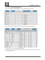
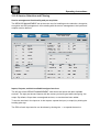
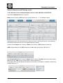
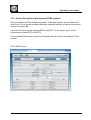
1
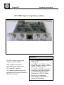
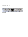
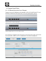
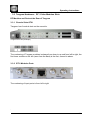
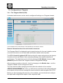
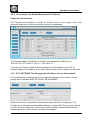
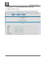
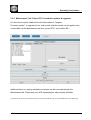
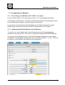
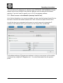
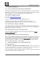
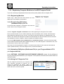
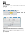
GT 01W Tangram with GT31 Modules (IP Gateway)
GT 01 WISI Tangram chassis
Tangram GT
Operating instructions
GT31 WISI Tangram IP gateway modules
Features:
The GT31 module is part of the
Tangram product portfolio.
WISI Tangram is an FPGA
technology based Headend for
FTTx and HFC networks.
The Tangram platform shows very
high density and is highly flexible for
all kinds of networks
Multi Transportstream reception for
DVB signals
4 x DVB-S / -S2 / -T/T2 / -C input
Gigabit Ethernet (SGMII) output for
MPTS and SPTS signals
32 x MPTS or SPTS output today
Demultiplex/ Remultiplex signals
for SPTS/ MPTS transmission
Modification of PSI /SI- Tables
Block pid / pid remapping
User friendly configuration via
standard Web browser
This page is intended to be empty
Tangram GT
Operating instructions
Table of contents
1
Safety Instructions............................................................................................................... 6
1.1
2
Technical Data / Mechanical Overview ............................................................................... 7
2.1
3
ESD Protection ............................................................................................................ 6
GT31 Module Front View ............................................................................................. 7
Installation, Configuration and Maintenance ....................................................................... 8
3.1
Module Installation ....................................................................................................... 8
3.2
Tangram Front IP Ports.............................................................................................. 10
3.2.1
3.3
IP / Ethernet Ports at the Front of Tangram .......................................................... 10
Tangram Hardware : RF / Video Modules Slots ........................................................ 11
3.3.1
Chassis Slots GT01 .............................................................................................. 11
3.3.2
GT31 Modules Ports ............................................................................................. 11
3.4
Configuration of Tangram .......................................................................................... 12
3.4.1
The Tangram Web UI (GUI) ................................................................................. 12
3.4.2
Connecting to the Default Management IP Address: ............................................ 13
3.4.3
GT11 SETTINGS Tab: Changing the IP Address to Your Own Network .............. 13
3.4.4
IP / Ethernet Ports Groups (using internal VLAN IDs) .......................................... 14
3.4.5
GT11 SETTINGS Tab: Throughput measurement ............................................... 15
3.5
Tangram GT11 / 12 Switch Modules / Main Control Page ......................................... 16
3.5.1
Main Status GT11- Control ................................................................................... 16
3.5.2
Maintenance Tab / Future GT11 Main Updates & Upgrades ................................ 18
3.6
Tangram GT11 / 12 Internal Switch / Control Tab...................................................... 17
3.6.1
Modules Tab on the GT11-Control ....................................................................... 17
3.6.2
Module Status and Settings .................................................................................. 17
3.7
Configuration of Modules ........................................................................................... 19
3.7.1
Connecting to the Modules (GT 31 SW 1.1 or newer) .......................................... 19
3.7.2
Adding Additional IP Addresses to the Modules ................................................... 19
3.7.3
Direct access to the Modules (backup Control Port) ............................................ 20
3.8
Tangram & SW Options ............................................................................................. 21
3.8.1
Connect to WISI Portal & Activating the Output Modules: .................................... 21
3.8.2
Serial Number / Linking to the Modules ................................................................ 21
3.8.3
Requesting Access to the wisiconnect.tv Portal ................................................... 21
3.8.4
Login to the wisiconnect.tv / chameleonconnect.tv ............................................... 21
3.9.
Uploading SW Upgrade to your Tangram Module GT31 ..................................... 21
3.10
Registering Tangram Modules to the WISI Tangram Portal ....................................... 22
3.10.1
Registering Modules .......................................................................................... 22
3.10.2
Downloading SW Options (entitlement file) to your PC ..................................... 22
3.10.3
Uploading SW Options (Entitlement File) to your Tangram Module GT31 ........ 22
3.10.4
Using the IP Supporter Tool .............................................................................. 22
3.11 Configuring Inputs ......................................................................................................... 23
3.11.1 Defining / adding inputs ............................................................................................. 23
3.13.2 Service Selection and Filtering .................................................................................. 25
Service Selection and Filtering (cont.) .................................................................................. 26
3.13.4 Adding and Removing Services to/from IP Outputs ................................................... 27
3.12 Service Decryption (with optional GT42 module) ......................................................... 28
3.14 Tangram Module settings ............................................................................................. 30
3.14.1 Add and configure Network interfaces ....................................................................... 31
3.14.3 Setting up DATE AND TIME ...................................................................................... 32
3.14.4 Module Software and SW options (Entitlement) ........................................................ 33
3.14.5 Module maintenance ................................................................................................. 34
3.14.6 Configuration Backup / Restore ................................................................................. 35
4. GT31 Module Status Information ...................................................................................... 36
Document Revision Information
Date
finished
2013-02-06
2013-03-11
2013-04-17
Document Rev.
1.48-1.49
1.50-1.53
1.54
GT31 SW
Version
1.0
1.0
1.1
Description
Name
First GT31 draft
Review Inputs, Updates
GT11 changes, Reviewed Inputs
KD
KD
KD
Tangram GT
Operating instructions
1 Safety Instructions
1.1 ESD Protection
This product contains electrostatic sensitive devices. These devices can be damaged
or effectively destroyed by electrostatic discharge (ESD) during unpacking,
installation, removal, storage, or shipment if incorrectly handled. Please note that
discharge might go unnoticed by a user. Always take normal static precautions when
handling the equipment!
2 Technical Data / Mechanical Overview
2.1 GT31 Module Front View
GT31 module view
Operating instructions
3 Installation, Configuration and Maintenance
3.1 Module Installation
The Tangram GTxx modules are single function modules. The modules are hotswappable and can be plugged into the chassis from the back. On the front side of the
Tangram chassis there are the switch modules, the power supplies and the fan tray. The
power supplies and the fan tray are situated behind the panels. Power supplies and the
fan tray can be replaced during operation.
The physical installation of GTxx modules, power supplies and fan modules into
Tangram GT01 chassis is described in detail in the GT01 & GTxx Installation Quick
Guides, please refer to them in case you have to insert or remove a module.
412 xxx
Operating instructions
This page is intended to be empty
-9-
Operating instructions
3.2 Tangram Front IP Ports
3.2.1 IP / Ethernet Ports at the Front of Tangram
Tangram has up to 9x GigE ports at the front side, 5x RJ-45 100/1000T with GT11 and
optionally an additional 4x SFP ports with GT12 at the upside position (Slot 8).
Tangram with GT11 Switch module (Slot 7)
Tangram equipped with GT11 & GT12 Switch modules
The numbering on Tangram ports is from down to up and from left to right, the first lower
Port from the left ( “MAN” ) on GT11 is dedicated for out-of-band management.
- 10 -
Operating instructions
3.3 Tangram Hardware : RF / Video Modules Slots
RF Modules and Ports at the Rear of Tangram
3.3.1 Chassis Slots GT01
Tangram has 6 module slots on the rear side.
Tangram rear view (Example)
The numbering of Tangram modules is always from down to up and from left to right, the
first lower module on the left (seen from the back) is the first, second is above.
3.3.2 GT31 Modules Ports
The numbering of input ports is from left to right
.
- 11 -
Operating instructions
3.4 Configuration of Tangram
3.4.1 The Tangram Web UI (GUI)
A standard web browser can be used to configure all settings on a Tangram chassis.
In the left field there are the Modules / Slots identified by the Chassis / Switch.
General information about the web interface structure
The Tangram Web UI is designed to get a logical structure for the user/ installer, and an
overview of the device via the side tabs and module details via the top tabs.
The GT11-Control & (optional) GT12 tab on the left contain settings about the chassis
& switch such as main Status, main networking Settings, the modules identified &
maintenance. The tabs below on the left side starting with M1 (Module 1) down to M6
(Module 6) are the links to the Tangram modules configuration settings:
After choosing a module on the left – the UI is changing to the Module view – and the
Tangram modules can be configured in detail.
The main interface while managing services within the modules is the modules
SERVICE MANAGEMENT tab. Here, you will have an overview of the configured inputs
and outputs, and you will also manage the service selection and decryption with GT42.
Before you start managing the services on the modules, you should add and configure
the inputs and configure the outputs in their respective tabs.
- 12 -
Operating instructions
3.4.2 Connecting to the Default Management IP Address:
Supported web browsers
The Tangram web interface is verified for Firefox version 9 and higher. Other web
browsers might work, but the functionality cannot be guaranteed.
The Tangram default IP address on the left front management “MAN” port is
192.168.1.20 (GT11 SW rel. <0.8.1.5 : 192.168.0.11)
To access the Tangram Web- Interface please set the IP address on your PC or
Network adaptor to an address in the same address subnet & use same network mask.
3.4.3 GT11 SETTINGS Tab: Changing the IP Address to Your Own Network
It is recommended to change the IP to a unique IP address in your network. Please
change the IP address under SETTINGS / NETWORKING.
Within the Network configuration following data has to be filled in completely: The
IP address, the Netmask and the default gateway. A known NTP Server source can be
used for the time-of-day sync, useful for the logs timestamp. When finished with the
changes press the “Save” button to activate the changes..
- 13 -
Operating instructions
3.4.4 IP / Ethernet Ports Groups (using internal VLAN IDs)
There are Port Groups to easily distribute video traffic of above 1 Gbit on Tangram.
GT11 Port Group A is representing internal VLAN ID=2 up to Group H with VID=9 and
they are available to choose in a pull-down menu. All external ports on Tangram are
untagged ports.
Tangram reserved Groups (VIDs 10-15 & 16):
- GT11 MGMT Port 0 using VID=1: Connection to GT switch and module web UI.
- Internal Management net uses VID=16: reserved for internal control.
- The additional internal Groups “I- M” (VID=10-15) are reserved for internal stream
distribution on Tangram.
Port Group-Member settings on GT11:
Port Group-Member settings on GT12:
GT11 & 12 Port Group- Member settings in the Main Setting Tabs
Settings in the example:
- GT11 Port 1: Connection to GT streaming net A (VID=2)
- GT11 Port 2: Connection to GT streaming net B (VID=3)
- GT11 Port 3: Connection to GT streaming net C (VID=4)
- GT11 Port 4: Connection to GT streaming net D (VID=5)
- GT12 Port 1: Connection to GT streaming net E (VID=6)
- GT12 Port 2: Connection to GT streaming net E (VID=6)
- GT12 Port 3: Connection to GT streaming net E (VID=6)
- GT12 Port 4: Connection to GT streaming net E (VID=6)
- 14 -
Operating instructions
3.4.5 GT11 SETTINGS Tab: Throughput measurement
Below of the Group-Member settings you find the button: Show current traffic
throughput
Sent & Received packets for each switch-port are shown, and Overflow packets and
CRC errors can be checked per port:
- 15 -
Operating instructions
3.5 Tangram GT11 / 12 Switch Modules / Main Control Page
3.5.1 Main Status GT11- Control
On the Tangram GT11-Control Status Tab you can monitor overall stats like Alarms,
Fans, Power, Temperature, Serial Number and main SW- Version of the Tangram
- 16 -
Operating instructions
3.6 Tangram GT11 / 12 Internal Switch / Control Tab
3.6.1 Modules Tab on the GT11-Control
.
3.6.2 Module Status and Settings
You can check and set the Modules on the Modules tab. You can switch them on /off
and you can reset them remotely. Additionally you can optionally configure (n+1)
Module Redundancy.
- 17 -
Operating instructions
3.6.3 Maintenance Tab / Future GT11 & modules updates & upgrades
In future there may be additional functionality added to Tangram.
Firmware update* or upgrade for the main switch and the moules can be applied very
comfortable via the Maintenance tab since recent GT11 and module SW.
Additional there is a syslog available and scripts can be executed through the
Maintenance tab. Please ask your WISI representative about scripts available.
*IP addresses set and Group membership will survive a Firmware update as long as not stated differently in the release notes.
- 18 -
Operating instructions
3.7 Configuration of Modules
3.7.1 Connecting to the Modules (GT 31 SW 1.1 or newer)
If your module has SW 1.0 or older please refer to 3.7.3 and upgrade the module.
The Tangram modules (SW >1.0) can be accessed through the front management port
by just choosing the module on the left column in the Web UI.
(to access all modules with the same Management IP-address through the switch,
please make sure that the IP ports 80 to 86 are opened with your Firewalls )
3.7.2
Adding additional IP Addresses to the Modules
To receive (e.g. event tables) and to send streams you need to setup streaming
interfaces to the Internal Port. This can be configured through the NETWORKING tab.
As an option it is possible to put an unique IP management address to every module
available through the Switch Management Port (e.g. Main address +1,+2, etc.). This can
be used e.g. to get SNMP- traps directly from the Modules.
- 19 -
Operating instructions
You can edit the IP addresses of a Module under SETTINGS / NETWORKING. Please
always remove and configure new network- address, the net mask plus the default
gateway. If you don’t want to specify, put in 0.0.0.0 as gateway address.
3.7.3 Direct access to the Modules (backup Control Port)
As a further alternative or to recover a problem you may use the backup Control Port on
the back of module with default address 192.168.1.20 and net mask 255.255.255.0.
As with the front port a standard web browser is used to connect by typing the IP
address in the address field to get access from the Control Port on the back.
If all address settings of Tangram are unknown or lost you can recover on the module
control port by using the IP Supporter tool – it can be downloaded from the product
portal.
- 20 -
Operating instructions
3.8 Tangram & SW Options
3.8.1 Connect to WISI Portal & Activating the Output Modules:
The Tangram modules GT2x & GT31 (not the Tangram chassis, nor the GT11) must be
registered at the WISI portal and activated through an entitlement file before they can be
used or upgraded. You can get / download that from WISI Web-Portal:
The WISI Tangram portal
Portal URL: http://www.wisiconnect.tv
Connect to the WISI portal using the URL: http://wisiconnect.tv
(in case wisiconnect.tv is down / not available temporarily, you can use
http://www.chameleonconnect.tv which offers the same functionality and data.
3.8.2 Serial Number / Linking to the Modules
The Tangram module to be activated can be accessed through the main management
page of the module web UI. Please copy / write down the serial number displayed in the
Status tab of the module to be activated.
3.8.3 Requesting Access to the wisiconnect.tv Portal
If you do not yet have a password for access to the portal, please click the Request
access to Tangram portal link.
3.8.4 Login to the wisiconnect.tv / chameleonconnect.tv
Enter your e-mail address and password, and click Login. Only with the first module you
have to register once for the Portal. Then after some time to generate your account or if
you have forgotten your password & clicked the Reset password link, an e-mail will be
sent to the entered e-mail address. The e-mail contains a hyper-link that you should
follow to confirm the request for a new password.
3.9.
Uploading SW Upgrade to your Tangram Module GT31
(via Tangram Web GUI)
Under SETTINGS / SOFTWARE AND ENTITLEMENT UPDATE, browse for the firmware file
you previously downloaded to your computer. Click Upload, and reboot the module when the
upload is ready /finished. Further information you can find in chapter 3.14.4.
To be able to apply an update to a Tangram module it must be first registered and activated
through the entitlement file which is described in 3.10.
- 21 -
Operating instructions
3.10 Registering Tangram Modules to the WISI Tangram Portal
If you do not have yet a password for access to the portal, please refer to chapter 3.8.3
3.10.1 Registering Modules
Please copy / write down the serial number out of the
Status tab of the module to be activated
3.10.2 Downloading SW Options
(entitlement file) to your PC
Go to the tab My Tangrams / Chameleons and enter the
serial number of your Tangram module.
Click the `Register Tangram / Chameleon` tab to start registering the Tangram GT31 module.
Enter the serial number of your module. Optionally, also enter Module name, Vendor, and Description
(these fields are intended for your own use, to be able to track and maintain your installed base). The
fields for SLA status and SW options are filled out automatically from the information stored in the WISI
Unit Data Base. Click the `Register´ button to register the Tangram module.
Go to the tab My Tangrams (or my Chameleons on Chameleonconnect) , and click the serial number
of the module to download SW options (entitlement file) for. In the Edit Tangram or Chameleon view, click
Download file. Save the file to your computer
After login and choosing Register Tangram / Chameleon tab number for the module to download SW
options (entitlement file). In the Edit Tangram view, choose Download file.
3.10.3 Uploading SW Options (Entitlement File) to your Tangram Module GT31
(via Tangram Web GUI)
Under SETTINGS / SOFTWARE AND ENTITLEMENT UPGRADE, browse for the entitlement
file you previously downloaded to your computer. Click Upload, and reboot the module when the
upload is ready.
3.10.4 Using the IP Supporter Tool
With the Tangram connected to your computer, and
your computer connected to Internet, you can
upload the entitlement file directly. Select your
Tangram module, and check the Entitlement from
WISI / a2b server, and click Upload.
- 22 -
Operating instructions
3.11 Configuring Inputs
To receive DVB streams you need to setup the sources. This can be configured through
the INPUT tab.
3.11.1 Defining / adding inputs
Add input:
1. Click the INPUTS tab, and Add
new input.
2. Choose Type and select the
appropriate
parameters
and
settings.
3. Click the SAVE button.
After clicking Save, the status of the input will be shown:
Status information
The status includes information about the interface (tuner etc.), and about services found.
Add / Edit more inputs
Re-iterate the “Add input” process.
- 23 -
Operating instructions
3.12 GT 31 Service Management
Click on the SERVICE MANAGEMENT tab to see available inputs and outputs.
Service IDs and PIDS of received Input services are shown and can be checked
Service IDs shown in the Tab SERVICE MANAGEMENT
The INPUTs and their PIDs are shown starting from INPUT 0 to INPUT n, depending on how many Inputs
are configured and received.
- 24 -
Operating instructions
3.12.2 Service Selection and Filtering
Service management functionality and pre-requisites
The SERVICE MANAGEMENT tab is the main view for handling service selection, decryption,
encryption and PID management. efore starting with the service management, the inputs and
outputs must be defined.
Inputs, Outputs, and their available/ assigned services
The left part of the SERVICE MANAGEMENT view shows the Inputs with their available
services. The right part shows Outputs with the names you have typed while configuring the
output. By default, Output have no assigned services, no services has been added.
To see the services in the inputs or in the outputs, expand the input (or output) by clicking the
heading plus sign.
The PIDs of each input service can be shown by clicking the + to expand the service.
- 25 -
Operating instructions
Service Selection and Filtering (cont.)
3.12.3 Structure of the available/assigned services under INPUTS and OUTPUTS
Input: Each Input/service has 3 columns;
Name (service names), SID (service id), and an edit arrow ” >” for adding to output.
Assigning services from the inputs to the outputs is done by clicking the arrow > and selecting
the output to add the service to in the appearing pop-up boxes.
Outputs: Each Output has 6 columns; Name (mux names), TSID (transport stream id),
ONID (Original Network id), NID (Network id), LCN (LCN type) and the edit arrow “>”
Each Output Service has 5 columns; Name (service name), Provider (service provider name),
SID (service id), LCN (service LCN number) and the edit arrow ”>” .
Every Name & ID can be changed by clicking on the entry in the table or resetted / removed by
clicking the arrow “>”
- 26 -
Operating instructions
3.12.4 Adding and Removing Services to/from IP Outputs
Adding services to the outputs
1. Click the edit arrow tailing an input service. When you click the arrow, an “Add / Connect”
pop-up will appear.
2. Move the mouse pointer to the Add pop-up.
3. Select the Output to add the service.
Adding all services to the outputs
1. Click the edit arrow tailing an input. When you click the arrow, an pop-up will appear with
“Connect transparently to” and “Add all services to”.
2. Select “Add all services to”, and select the Output to add services to.
Removing services from the outputs
Removing a single service from an output
1. Click the edit arrow > of an output service.
2. Click “Remove” in the pop-up window.
Removing all services from an output
1. Click the edit arrow > of an output.
2. Click “Remove services” in the pop-up window.
- 27 -
Operating instructions
3.13 Service Decryption (with optional GT42 module)
With one additional GT42 module its possible to decrypt services via four different CI
slots. Each CI slot can be handled individually regarding settings of input source and bit
rate for the used CAM.
Up to four IP inputs can be created (SPTS or MPTS). For the output, up to four IP
outputs can be used (SPTS or MPTS).
A more detailed description of Service Decryption can be found in the separate GT42
manual.
GT42 INPUT menu:
- 28 -
Operating instructions
GT 42 OUTPUT MENU:
In the service management menu one chose decryption for the wanted services to be
decrypted and also connect the decrypted (and not decrypted) services to the created
outputs.
NOTE! The number of services that can be decrypted simultanously is depending on the
used CAM and smartcard.
- 29 -
Operating instructions
3.14 Tangram overall module settings
Under the module SETTINGS tab – module specific settings are managed:
NETWORKING
Networking settings for defining and configuring IP interfaces, and for setting the capabilities for
the defined IP interfaces.
Note: Every Tangram module has an extra IP port on the Tangram back for separate 10/100
Ethernet management (“Control Port”, default IP 192.168.1.20/24), the module internal GigE
port is switched through GT11 switch for streaming & main management.
There are no IP addresses defined for the GigE streaming per default and they have to be set
accordingly to customer network.
Example of Networking setup
- 30 -
Operating instructions
3.14.1 Add and configure Network interfaces
1. Click on NETWORKING in the SETTINGS tab
2. Click Add new interface
3. Type a name for the interface
4. Enter the IPv4 address, the Netmask and the Gateway
5. Select the capabilities needed for the interface (e.g. for Streaming the VLAN ID)
6. Click SAVE
- 31 -
Operating instructions
3.14.3 Setting up DATE AND TIME
To synchronize Tangram modules with a time source you can either use NTP protocol
through the IP interfaces or Time information delivered by the received MPTS- Streams.
1. Click on DATE AND TIME in the SETTINGS tab
2. Click EDIT
3. Select the Time zone, automatic or manual daylight saving timer and the reachable
NTP servers (separate by adding a comma after each address)
4. Click SAVE
5. If no NTP is available/ configured a Stream source including that information can be
used to synchronize the date & time of Tangram modules
(Note: NTP servers can be connected from the modules external or internal GigE ports and switched
through GT11 switch. There are no IP addresses defined for the internal Interface for NTP use per
default and they and the gateway have to be set for every module accordingly to customer management
network. )
Example of a Date & time setting using a NTP server
- 32 -
Operating instructions
3.14.4 Module Software and SW options (Entitlement)
If a module is shipped from factory it has no License /
Entitlement for operation. Both FW and SW options are
uploaded via SOFTWARE AND ENTITLEMENT
UPGRADE in the SETTINGS tab. Additionally, there is
status information available about the running software
version, and if a new software is uploaded, also about
the latest uploaded (not yet running) software version.
Uploading software options / Entitlement
•Click UPLOAD. Click “Browse” in the pop-up to browse for the software options file (*.ent) for this specific
Tangram module
Note: The SW options file will have the format <serial number>.ent. If you need to, you can download the
entitlement file from the Wisiconnect.tv portal or please ask your WISI representative
•Locate the software options file on your PC, and select it
•Click the Upload button
Uploading new Firmware
•Click UPLOAD. Click “Browse” in the pop-up, and select the software file (*.bin file) to be uploaded from
your PC
•Click the Upload button
•Wait for the upload complete message before rebooting the module
•Reboot the module in your maintenance window
- 33 -
Operating instructions
3.14.5 Module maintenance
Module maintenance functions are available within the Maintenance tab:
Reboot of the module
Some operations, such as upgrading the software, require a reboot to get it active.
Click the Reboot button to reboot the unit.
During the rebooting process, “Rebooting” will be shown.
After rebooting, the web GUI will go automatically to the STATUS tab.
- 34 -
Operating instructions
3.14.6 Configuration Backup / Restore
Factory reset
The Tangram module can be reset to the same status as when delivered from the factory.
SETTINGS tab, and MAINTENANCE.
Go to the
Before you Click on FACTORY RESET please always do a backup of your last configuration as described
below ! It may help you to save time & effort to get back to your original setup.
Backup and restore (saving & restoring configuration)
The backup and restore functionality gives you the possibility to save the complete configuration
of a Tangram / module to your PC. The stored config file is in readable xml format.
The backup file can be used for e.g. copying /clone configurations between different
installations, or keeping a possibility to upload back the original configuration to a module after
a change.
- 35 -
Operating instructions
4. GT31 Module Status Information
The STATUS tab gives a general overview over the Tangram module. This page is also
the starting page for the Module UI.
MODULE IDENTIFICATION
Serial number and the HW version is shown. Further, there are three editable fields;
Name, Location and Description. Choosing EDIT below the box enables you to save
your own selected information about this Tangram module.
CONFIGURATION
The configuration box shows you the Operation mode, the Software version, and the
enabled SW options. A warning will be shown if no operation mode is selected.
STATUS
Uptime (from last reboot), and current module temperature.
SERVICE LICENCE AGREEMENT
Shows if the Tangram is registered at the WISI portal, and the expiry date of the service
level agreement.
- 36 -
Operating instructions
5. Support and further information
For further information and help, please contact our support organisations:
E-mail: [email protected]
Telephone: +49 (0)7233 / 66-621
User manual and installation guide updates
Updates to the user manual and the installation guide are available at the Website
www.wisi.de and through the wisiconnect Portal.
- 37 -
Operating instructions
04/13
- 38 -