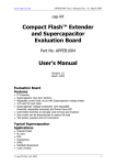
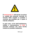
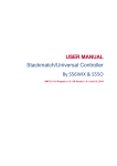
1
It is user RESPONSIBILITY to check
that these “Wiring instructions” refers
to product model and version that will
be used.
In any case, regarding installation,
use and maintenance, the complete
Sanyo Denki instruction manual
TAKES PRIORITY. The complete Sanyo
Denki instruction manual is included,
in PDF format, in the Starter Kit CDRom and the printed version is
available on demand.
R.T.A. srl
MOTION CONTROL SYSTEMS
Wiring Procedure
This document summarizes how to build cables for motor,
encoder and power supply for Sanyo Denki AC Servo
Systems “QS1A” and “RS1A” Series.
R.T.A. s.r.l.
Via E. Mattei – Frazione DIVISA
27020 MARCIGNAGO (PV)
Tel. +39.0382.929.855 - Fax +39.0382.929.150
Internet: http://www.rta.it - e-mail: [email protected]
R.T.A.
DEUTSCHLAND GmbH
Bublitzer Straße, 34
40599 DÜSSELDORF (Germany)
Tel. +49.211.749.668.60-Fax +49.211.749.668.66
Internet: http://www.rta-deutschland.de
e-mail: [email protected]
R.T.A. IBERICA
MOTION CONTROL SYSTEMS S.L.
C/Generalitat 22, 1° 3°
08850 GAVA – BARCELONA (Spain)
Tel. +34.936.388.805-Fax +34.936.334.595
Internet: http://www.rta-iberica.es
e-mail: [email protected]
R.T.A. s.r.l. – MCB_ME04 – 11/08
Contents
1-
P3 AND P5 SERIES MOTOR CABLE – R2 SERIES MOTOR CABLE................................. 4
2-
P3 AND P5 SERIES MOTOR CABLE EQUIPPED WITH HOLDING BRAKE POWER
SUPPLY................................................................................................................................. 6
3-
P3 AND P5 SERIES ENCODER CABLE .............................................................................. 9
4-
R2 SERIES ENCODER CABLE .......................................................................................... 11
5-
POWER SUPPLY CABLE FOR “QS1A” AND “RS1A” SERIES SERVO AMPLIFIERS
– MODELS UP TO 30 A ...................................................................................................... 14
6-
POWER SUPPLY CABLE FOR “QS1A” AND “RS1A” SERIES SERVO AMPLIFIERS
– MODEL 50 A..................................................................................................................... 15
7-
POWER SUPPLY CABLE FOR “QS1A” AND “RS1A” SERIES SERVO AMPLIFIERS
– MODEL 100 A................................................................................................................... 16
8-
MOTOR CABLE FOR P20B10150D, Q2AA10150B AND Q1AA10150D MOTOR
TYPES ................................................................................................................................. 16
9-
MOTOR CABLE FOR P60B13150H AND Q2AA13150H MOTOR TYPES ........................ 19
10-
MOTOR CABLE FOR Q1AA13300D MOTOR TYPE.......................................................... 21
11-
ENCODER CABLE FOR P20B10150D, P60B13150H, Q1AA13300D, Q1AA10150D,
Q2AA10150B AND Q2AA13150H MOTOR TYPES ........................................................... 22
12-
BRAKE CABLE FOR P20B10150D, P60B13150H, Q1AA10150D, Q1AA13300D,
Q2AA10150B AND Q2AA13150H MOTOR TYPES ........................................................... 25
13-
BRAKE CABLE FOR R2 SERIES MOTOR TYPE .............................................................. 26
R.T.A. s.r.l. – MCB_ME04 – 11/08
2/23
Sanyo Denki brushless AC servo systems “QS1A” and “RS1A” Series
These instructions summarize how to build cables for the
following servo motors and servo amplifiers:
-
P20B10150D
-
P30B04005D
P30B04010D
P30B06020D
P30B06040D
P30B08075D
-
P50B04010D
P50B05020D
P50B07040D
P50B08100H
-
P60B13150H
-
Q1AA10150D
Q1AA13300D
-
Q2AA10150B
Q2AA13150H
-
R2AA04010F
R2AA06020F
R2AA06040F
R2AA08075F
-
QS1A01AA
QS1A03AA
QS1A05AA
QS1A10AA
RS1A01AA
RS1A03AA
RS1A05AA
RS1A10AA
Warning:
The following document describes how to build cables
having length of 10 meters maximum. In case of needing
flex chain cables or cables longer than 10 meters, please
contact RTA technical department.
R.T.A. s.r.l. – MCB_ME04 – 11/08
3/27
1- P3 AND P5 SERIES MOTOR CABLE – R2 SERIES MOTOR CABLE
Phoenix Contact Plug
5.08
IC2.5/3
AMP Plug 182647 1
Termo Contracting sheath
MOTOR SIDE
3 conductors
AMPLIFIER SIDE
Termo Contracting
sheath
Grounding cable
Figure 1
1.1-
Components
Components
Quantity
4
1
1
1
100mm
Description
AMP pins type 1-66101-9
AMP connector type 182647-1
AMP cable clamp type 182658-1
Phoenix Contact connector type IC2.5/3-STF-5.08
Three conductors shielded cable. Cross Section Area: 1 mm²
Grounding cable. Colour: yellow/green. Cross Section Area: 1.5 mm²
Crimp the Insulated lugs at the end
of the three conductors and insert
them in the Phoenix Contact
connector.
3
Insulated lugs. Cross Section Area: 1 mm²
1
Round soldering lug for grounding cable. Cross Section Area: 1.5
mm²
1.2-
Notes
Wiring procedure
Be sure to use the right tool to wire the cable on the motor side. RTA recommends AMP PRO-CRIMPER II
hand tool, model 58495-1 with die assembly 58495-2.
Motor Side (AMP connector type 182647-1)
Wiring
Check
Point
1
2
3
4
5
Description
Cut 10mm of the external protection sheath.
Cut 3mm of insulator on every single internal conductor.
Crimp every single internal conductor using AMP PRO-CRIMPER II model 58495-1.
Be sure to use the 24-20 AWG position of the AMP Pro-Crimper hand tool.
Crimp the shield in an AMP pin code 1-66101-9.
R.T.A. s.r.l. – MCB_ME04 – 11/08
4/27
Amplifier Side (Phoenix Contact connector type IC2.5/3-STF-5.08)
Wiring
Check
Point
1
2
3
4
Cut 10mm of the external protection sheath.
Cut 3mm of insulator on every single internal conductor.
Crimp the lugs on the three conductors of the cable.
Insert the lugs in the Phoenix Contact connector type IC2.5/3-STF-5.08.
1.3-
Ground wiring
Description
On the amplifier side, weld the shield to the 100 mm long ground cable. The other side of the ground cable must
be welded to the round soldering lug (see figure N. 1).
Grounding Cable:
Length:
Colour:
100 mm
yellow/green
Remember to insulate the soldering points by appropriate thermo-contracting sheath
1.4-
Wiring Diagram
1
3
2
4
Pin 1:
Pin 2:
Pin 3:
Pin 4:
U
V
Phase
Phase
Phase
Pin 1:
Pin 2:
Pin 3:
Shield
U
V
W
Phase
Phase
Phase
Figure 2
1.5 - Mounting Sequence
Mounting
Check
Description
Point
1
Insert the pins in the AMP connector type 182647-1 as described in figure N° 2
2
Screw the connector 182647-1 and the cable clamp 182658-1 together.
3
Complete this sequence mounting the cable clamp.
R.T.A. s.r.l. – MCB_ME04 – 11/08
5/27
2- P3 AND P5 SERIES MOTOR CABLE EQUIPPED WITH HOLDING BRAKE
POWER SUPPLY
Figure 3
2.1-
Components
Components
Quantity
6
2
1
1
1
100mm
Description
AMP pins type 1-66101-9.
AMP keying connector type 200821-1.
AMP connector type 182645-1.
AMP cable clamp type 182663-1.
Phoenix Contact connector type IC2.5/3-STF-5.08.
Three conductors shielded cable. Cross Section Area: 1 mm².
Two conductors shielded cable. Cross Section Area: 0.75 mm².
Grounding cable. Colour: yellow/green. Cross Section Area: 1.5
mm².
3
Insulated lugs. Cross Section Area: 1 mm²
1
Round soldering lug for grounding cable. Cross Section Area: 1.5
mm²
R.T.A. s.r.l. – MCB_ME04 – 11/08
Notes
Crimp the Insulated lugs at the end
of the three conductors and insert
them in the Phoenix Contact
connector.
6/27
2.2-
Wiring procedure
Be sure to use the right tool to wire the cable on the motor side. RTA recommends AMP PRO-CRIMPER II
hand tool, model 58495-1 with die assembly 58495-2.
Motor Side (AMP connector type 182645-1)
Wiring
Check
Point
1
2
3
4
5
6
7
Description
Cut 10mm of the external protection sheath on both motor and brake cable.
Cut 3mm of insulator on every single internal conductor.
Crimp every single internal conductor using AMP PRO-CRIMPER II model 58495-1.
Be sure to use the 24-20 AWG position of the AMP Pro-Crimper hand tool.
Crimp the shields of both, motor and brake cable, on the same connector pin: PIN N° 4.
Crimp the shields in an AMP pin code 1-66101-9.
Insert two AMP keying connector type 200821-1 in the AMP connector, position 5 and 8 see figure N° 4
Amplifier Side (Phoenix Contact connector type IC2.5/3-STF-5.08)
Wiring
Check
Point
1
2
3
4
Description
Cut 10mm of the external protection sheath.
Cut 3mm of insulator on every single internal conductor.
Crimp the lugs on the three conductors of the cable.
Insert the lugs in the Phoenix Contact connector type IC2.5/3-STF-5.08.
2.3 - Ground wiring
On the amplifier side, weld the shield to the 100 mm long ground cable. The other side of the ground cable must
be welded to the round soldering lug see figure N° 3.
Grounding Cable:
Length:
Colour:
100 mm
yellow/green
Remember to insulate the soldering points by appropriate thermo-contracting sheath
R.T.A. s.r.l. – MCB_ME04 – 11/08
7/27
2.4-
Wiring diagram
1
2
3
1 (U)
4
5
6
7
8
9
2 (V)
3 (W)
Pin 1:
Pin 2:
Pin 3:
Pin 4:
Pin 5:
Pin 6:
Pin 7:
Pin 8:
Pin 9:
U Phase
V Phase
W Phase
Shield (of both cable)
Keying plug
BRAKE CABLE
Not connected
Keying plug
BRAKE CABLE
Pin 1:
Pin 2:
Pin 3:
U
V
W
Phase
Phase
Phase
Figure 4
2.5 -
Mounting Sequence
Mounting
Check
Description
Point
1
Insert the pins in the AMP connector type 182645-1 as described in figure N° 4
2
Screw the connector 182645-1 and the cable clamp 182663-1 together.
3
Complete this sequence mounting the cable clamp.
R.T.A. s.r.l. – MCB_ME04 – 11/08
8/27
3- P3 AND P5 SERIES ENCODER CABLE
Figure 5
3.1 - Components
Components
Quantity
8
1
1
1
1
1
Descrption
AMP pin type 1-66109-7
AMP pin type 1-66101-9
AMP connector type 182645-1
AMP cable clamp type 182663-1
3M connector type 10120-3000PE
3M housing type 10320-52A0-008
8 connectors twisted pair connection shielded cable. Cross Section
Area: at least 0.35 mm²
Insulating tape.
Notes
3.2 - Wiring procedure
Be sure to use the right tool to wire the cable on the motor side. RTA recommends AMP PRO-CRIMPER II
hand tool, model 58495-1 with die assembly 58495-2.
Motor Side (AMP connector type 182645-1)
Wiring
Check
Description
Point
1
Cut 15mm of the external protection sheath.
2
Cut 3mm of insulator on every single internal conductor.
3
Crimp every single internal conductor using AMP PRO-CRIMPER II code 58495-1.
Crimp the 8 signal cables with AMP pins type 1-66109-7. Use the 28-24 AWG position of AMP Pro4
Crimper hand tool.
Crimp the shield with an AMP pin type 1-66101-9. Use the 24-20 AWG position of AMP Pro-Crimper
5
hand tool.
R.T.A. s.r.l. – MCB_ME04 – 11/08
9/27
Amplifier Side (3M connector type 10120-3000PE)
Amplifier Side
Check
Point
1
2
3
4
5
6
7
Description
Notes
Cut 20mm of the external protection sheath.
Insert the “L” metallic plate in the cable.
Cut 3mm of insulator on every single internal conductors.
Roll up and weld the shield for a length of 10mm.
Sold the conductors in the 3M 10120-3000PE pins.
Sold the shield on the “L” metallic plate.
Fasten the metallic plate to the cable and close the 3M housing
10320-52A0-008.
Follow the diagram in figure N° 6
3.3 – Wiring diagram
Twisted pair
Twisted pair
Twisted pair
Twisted pair
Shield
Short circuit this two pins
WARNING:
For the parts marked
Use twisted pair shielded cable.
Short circuit this two pins
Shield
Metallic
Cable gland
Feather
Figure 6
R.T.A. s.r.l. – MCB_ME04 – 11/08
10/27
Warning: remember to protect the shield inside the AMP connector
182645-1 by insulated tape or thermo-contracting sheath.
3.4-
Mounting sequence
Mounting
Check
Description
Point
1
Insert the pins in the AMP connector type 182645-1 as described in figure N° 6
2
Screw the connector 182645-1 and the cable clamp 182663-1 together.
3
Complete this sequence mounting the cable clamp.
4- R2 SERIES ENCODER CABLE
M. Connector
3M 10120-3000PE
AMP Housing
182663-1
Housing 3M
10320-52A0-008
AMP Connector
206705-2
Insulating tape
AMP Contact
1-66107-1
AMP Contact
1-66099-5
MOTOR SIDE
AMPLIFIER SIDE
Shielded cable2
3x2x0.35mm
Figure 7
4.1-
Components
COMPONENTS
Quantity
6
1
1
1
1
1
Description
AMP pin type 1-66107-1
AMP pin type 1-66099-5
AMP connector type 206705-2
AMP cable clamp type 182663-1
3M connector type 10120-3000PE
3M housing type 10320-52A0-008
6 conductors twisted pair shielded cable.
Cross Section Area: at least 0.35 mm2.
Insulating tape.
Thermo contracting sheat Ø 3 mm.
R.T.A. s.r.l. – MCB_ME04 – 11/08
Notes
11/27
4.2 - Wiring Procedure
Be sure to use the right tool to wire the cable on the motor side. RTA recommends AMP PRO-CRIMPER II
hand tool, model 58495-1 with die assembly 58495-2.
Motor Side (AMP connector type 206705-2)
Wiring
Check
Description
Point
1
Cut 25 mm of the external protection sheath.
2
Cut 4 mm of insulator on every single internal conductor.
3
Crimp every single internal coductor using AMP PRO-CRIMPER II code 58495-1.
Crimp the 6 signal cables with AMP pins type 1-66107-1. Use the 28-24 AWG position of AMP Pro4
Crimper hand tool.
Crimp the shield with AMP pins type 1-66099-5. Use the 24-20 AWG position of AMP Pro-Crimper
5
hand tool.
8
Insert the crimped pins in the AMP connector 206705-2 (Figure 8).
6
Screw the connector 206705-2 and the cable clamp 182663-1 together.
7
Insert the cable clamp.
Amplifier Side (3M connector type 10120-3000PE)
Wiring
Check Point
1
2
3
4
5
6
7
Description
Cut 20 mm of the external protection sheath.
Insert the “L” metallic plate in the cable.
Cut 3 mm of insulator on every single internal conductors.
Roll up and weld the shield for a length of 10 mm.
Sold the conductors in the 3M 10120-3000PE pins (Figure 8).
Sold the shield on the “L” metallic plate.
Fasten the metallic plate to the cable and close the 3M cable clamp 10320-52A0-008.
R.T.A. s.r.l. – MCB_ME04 – 11/08
12/27
4.3-
Wiring Diagram
Pin 1
Pin 13
Twisted pair
Pin 2
Pin 5
Pin 14
Pin 1
Twisted pair
Pin 6
Pin 7
Pin 2
Pin 19
Twisted pair
Pin 8
Pin 9
Pin 20
Shield
Shield
Metallic
cable gland
feather
WARNING:
For the parts marked
used twisted pair shielded cable
Figure 8
Warning: remember to protect the shield inside the AMP connector, type
206705-2 by insulated tape or thermo contracting sheath.
R.T.A. s.r.l. – MCB_ME04 – 11/08
13/27
5- POWER SUPPLY CABLE FOR “QS1A” AND “RS1A” SERIES SERVO
AMPLIFIERS – MODELS UP TO 30 A
Figure 9
5.1-
Components
Components
Quantity
Description
Phoenix Contact connector type MSTB2.5/5-STF-5.08
1
Number four or five wires. Cross Section Area: 1 mm².
4
Insulated lugs. Cross Section Area: 1 mm².
Notes
When your power supply is
230VAC single phase, use four
wires. Otherwise when your power
supply is 230VAC three phase, use
five wires.
Crimp the Insulated lugs at the end
of the conductors and insert them
in the Phoenix Contact connector.
Warning: When your power supply is 230VAC single phase, DO NOT USE PIN N°2.
R.T.A. s.r.l. – MCB_ME04 – 11/08
14/27
5.2-
Wiring diagram
Figure 10
6- POWER SUPPLY CABLE FOR “QS1A” AND “RS1A” SERIES SERVO
AMPLIFIERS – MODEL 50 A
Figure 11
6.1-
Components
Components
Quantity
Description
Phoenix Contact connector type MSTB2.5/5-STF-5.08
1
Number four or five wires. Cross Section Area: 2.5 mm².
4
Insulated lugs. Cross Section Area: 2.5 mm².
Notes
When your power supply is
230VAC single phase, use four
wires. Otherwise when your power
supply is 230VAC three phase, use
five wires.
Crimp the Insulated lugs at the end
of the conductors and insert them
in the Phoenix Contact connector.
Warning: When your power supply is 230VAC single phase, DO NOT USE PIN N°2.
R.T.A. s.r.l. – MCB_ME04 – 11/08
15/27
6.2-
Wiring diagram
Figure 12
7- POWER SUPPLY CABLE FOR “QS1A” AND “RS1A” SERIES SERVO
AMPLIFIERS – MODEL 100 A
To build this supply cable, please refer to the complete Sanyo Denki instruction
manual.
8- MOTOR CABLE FOR P20B10150D, Q2AA10150B AND Q1AA10150D
MOTOR TYPES
DDK Cable clamp
DDK Connector
Thermo-contracting sheath
Phoenix Contact Connector
type IC 2.5/3 STF-5.08
Thermo-contracting sheath
Shielded cable
2
3x2.5mm
Cable. Cross Section Area: 1.5 mm
GI/VE
Round soldering lug.
2
Cross Section Area: 4mm
Figure 13
R.T.A. s.r.l. – MCB_ME04 – 11/08
16/27
2
8.1-
Components
Components
Quantity
Description
DDK connector type DMS 3106 A20 15S
1
DDK cable clamp type DMS 3057 12A
1
Phoenix Contact connector type IC2.5/3-STF-5.08
1
Three conductors shielded cable. Cross Section Area: 2.5 mm²
100mm Grounding cable. Colour: yellow/green. Cross Section Area: 1.5 mm²
Notes
Crimp the Insulated lugs at the end
of the three conductors and insert
them in the Phoenix Contact
connector.
3
Insulated lugs. Cross Section Area: 2.5 mm²
1
Round soldering lug for grounding cable. Cross Section Area: 4 mm²
Thermo-contracting sheath. Ø 19 mm
Thermo-contracting sheath. Ø 3 mm
8.2-
Wiring procedure
Motor Side
Check
Point
1
2
3
4
5
6
8.3-
Description
Insert the DDK cable clamp type DMS 3057 12A in the cable.
Cut 30mm of the external protection sheath.
Cut 6mm of insulator on every single internal conductors.
Roll up and weld the shield. Insert the welded shield in 16mm of
thermo-contracting sheath Ø 3mm.
Sold the conductors and the shield in the DDK DMS 3106 A20 15S
pins.
Screw the cable clamp and the connector together.
Notes
Follow the diagram in figure N° 14
Wiring procedure
Amplifier Side
Check
point
1
2
3
4
5
6
7
8
9
Description
Insert the cable in 40mm of thermo-contracting sheath Ø 19mm.
Cut 35mm of the external protection sheath.
Cut 6mm of insulator on every single internal conductors.
Crimp every single internal conductors with insulated lugs.
Roll up and weld the shield for a length of 10mm.
Cut 8mm of insulator on both sides of the grounding cable.
Weld one side on the grounding cable to the round soldering lug.
Sold the other side of the grounding cable to the shield and
insulate the soldering point by thermo-contracting sheath for a
length of 10mm.
Screw the conductors in the Phoenix Contact connector type
IC2.5/3-STF-5.08.
R.T.A. s.r.l. – MCB_ME04 – 11/08
Notes
Follow the diagram in figure N° 14
17/27
8.4-
Wiring diagram
1
2
3
Amplifier Side
Motor Side
Phoenix Contact
IC2.5/3-STF-5.08
DDK DMS 3106A20 15S
1[U]
A
2[V]
B
3[W]
C
Grounding cable
shield
D
Figure 14
R.T.A. s.r.l. – MCB_ME04 – 11/08
18/27
9- MOTOR CABLE FOR P60B13150H AND Q2AA13150H MOTOR TYPES
DDK Cable clamp
Insulated lugs. Cross Section Area: 2.5mm
DDK Connector
2
Thermo-contracting sheath
Phoenix Contact connector
type IC 2.5/3 STF-5.08
Thermo-contracting sheath
Shielded cable
2
3x2.5mm
Cable. Cross Section Area: 1.5mm
GI/VE
2
Round soldering lug.2
Cross Section Area: 4mm
Figure 15
9.1- Components
Quantity
Description
DDK connector type DMS 3106 A24 11S
1
DDK cable clamp type DMS 3057 16A
1
Phoenix Contact connector type IC2.5/3-STF-5.08
1
Three conductors shielded cable. Cross Section Area: 2.5 mm²
160mm Grounding cable. Colour: yellow/green. Cross Section Area: 1.5 mm²
3
Insulated lugs. Cross Section Area: 2.5 mm²
1
Round soldering lug for grounding cable. Cross Section Area: 4 mm²
Thermo-contracting sheath. Ø 3 mm
Thermo-contracting sheath. Ø 19 mm
Notes
9.2- Wiring procedure
Motor Side
Check
Point
1
2
3
4
5
6
7
Description
Notes
Insert the DDK cable clamp type DMS 3057 16A in the cable.
Cut 30mm of the external protection sheath.
Cut 6mm of insulator on every single internal conductors.
Cut the grounding cable for a length of 60mm. Cut 6mm of the
insulator on both side of this one.
Roll up and weld the shield for a length of 10mm. Sold one side of
the ground cable to the shield.
Sold the conductors, the shield and the ground cable in the DDK
DMS 3106 A24 11S pins.
Screw the cable clamp and the connector together.
R.T.A. s.r.l. – MCB_ME04 – 11/08
Remember
to
insulate
the
soldering point by 20mm of
thermo-contracting sheath Ø 3
mm.
Follow the diagram in figure N° 16
19/27
9.3- Wiring procedure
Amplifier Side
Fase
1
2
3
4
5
6
7
8
9
Descrizione
Insert the cable in 40mm of thermo-contracting sheath Ø 19mm.
Cut 35mm of the external protection sheath.
Cut 6mm of insulator on every single internal conductors.
Crimp every single internal conductors with insulated lugs.
Roll up and weld the shield for a length of 10mm.
Cut 8mm of insulator on both sides of the 100mm long grounding
cable.
Weld one side on the grounding cable to the round soldering lug.
Sold the other side of the grounding cable to the shield and
insulate the soldering point by thermo-contracting sheath for a
length of 10mm.
Screw the conductors in the Phoenix Contact connector type
IC2.5/3-STF-5.08.
Note
Follow the diagram in figure N° 16
9.4- Wiring diagram
Amplifier Side
Motor Side
1
Phoenix Contact
IC2.5/3-STF-5.08
DDK DMS 3106A24 11S
2
1[U]
D
3
2[V]
E
3[W]
F
Ground Cable
Shield
G, H (*)
Figure 16
(*) Warning: short-circuit pins G and H by ground cable.
R.T.A. s.r.l. – MCB_ME04 – 11/08
20/27
10- MOTOR CABLE FOR Q1AA13300D MOTOR TYPE
DDK cable clamp
Cable lugs in fork form.
DDK Connector
2
Thermo-contracting sheath
Ø 30mm
Thermo-contracting sheath
Shielded cable
2
Cable. Cross Section Area: 2.5mm GI/VE
Round soldering lug.
Cross Section Area: 4mm 2
Figure 17
10.1- Components
Quantity
Description
DDK connector type DMS 3106 A24 11S
1
DDK cable clamp type DMS 3057 16A
1
Three conductors shielded cable. Cross Section Area: 4 mm²
160mm Grounding cable. Colour: yellow/green. Cross Section Area: 2.5 mm²
3
Cable lugs in fork form. Cross Section Area: 4 mm²
1
Round soldering lug for grounding cable. Cross Section Area: 4 mm²
Thermo-contracting sheath Ø 3 mm
Thermo-contracting sheath Ø 30 mm
Notes
10.2- Wiring procedure
Motor Side
Check
Point
1
2
3
4
5
6
7
Description
Notes
Insert the DDK cable clamp type DMS 3057 16A in the cable.
Cut 30mm of the external protection sheath.
Cut 6mm of insulator on every single internal conductors.
Cut the grounding cable for a length of 60mm. Cut 6mm of the
insulator on both side of this one.
Roll up and weld the shield for a length of 10mm. Sold one side of
the ground cable to the shield.
Sold the conductors, the shield and the ground cable in the DDK
DMS 3106 A24 11S pins.
Screw the cable clamp and the connector together.
R.T.A. s.r.l. – MCB_ME04 – 11/08
Remember
to
insulate
the
soldering point by 20mm of
thermo-contracting sheath Ø 3
mm.
Follow the diagram in TABLE N° 1
21/27
10.3- Wiring procedure
Amplifier Side
Check
Point
1
2
3
4
5
6
7
8
Description
Notes
Insert the cable in 50mm of thermo-contracting sheath Ø 30mm.
Cut 35mm of the external protection sheath.
Cut 10mm of insulator on every single internal conductors.
Crimp every single internal conductors with insulated lugs.
Roll up and weld the shield for a length of 10mm.
Cut 8mm of insulator on both sides of 100mm long grounding
cable.
Weld one side on the grounding cable to the round soldering lug.
Sold the other side of the grounding cable to the shield and
insulate the soldering point by thermo-contracting sheath for a
length of 10mm.
10.4- Wiring diagram
TABLE 1
Amplifier Side
Motor Side
Insulated lugs
DDK DMS 3106A24 11S
[U]
D
[V]
E
[W]
F
Ground cable
G, H (*)
Shield
(*) Warning: short-circuit pins G and H by ground cable.
11- ENCODER CABLE FOR P20B10150D, P60B13150H, Q1AA13300D,
Q1AA10150D, Q2AA10150B AND Q2AA13150H MOTOR TYPES
DDK cable clamp
3M plug connector: 10120-3000PE
3M housing: 10320-52A0-008
DDK Connector
Insulating tape
Shielded cable2
Figure 18
R.T.A. s.r.l. – MCB_ME04 – 11/08
22/27
11.1- Components
Quantity
Description
DDK connector type DMS 3106 A20 29S
1
DDK cable clamp type DMS 3057 12A
1
8 connectors twisted pair connection shielded cable. Cross Section
Area: at least 0.35 mm²
3M connector type 10120-3000PE
1
3M cable clamp type 10320-52A0-008
1
Thermo-contracting sheath Ø 3 mm
Notes
11.2- Wiring procedure
Motor Side
Check
Point
1
2
3
4
5
6
7
Description
Notes
Insert the DDK cable clamp type DMS 3057 12A in the cable.
Cut 30mm of the external protection sheath.
Cut 5mm of insulator on every single internal conductors.
Roll up and weld the shield for a length of 10mm.
Sold the conductors and the shield in the DDK DMS 3106 A20 29S
pins.
Insulate the end of the cable by insulated tape.
Screw the cable clamp and the connector together.
Remember
to
insulate
the
soldering point by 20mm of
thermo-contracting sheath Ø 3
mm.
Follow the diagram in figure N° 19
11.3- Wiring procedure
Amplifier Side
Check
Point
1
2
3
4
5
6
7
Description
Cut 20mm of the external protection sheath.
Insert the “L” metallic plate in the cable.
Cut 3mm of insulator on every single internal conductors.
Roll up and weld the shield for a length of 10mm.
Sold the conductors in the 3M 10120-3000PE pins.
Sold the shield to the “L” metallic plate.
Fasten the metallic plate to the cable and close the 3M cable
clamp type 10320-52A0-008.
R.T.A. s.r.l. – MCB_ME04 – 11/08
Notes
Follow the diagram in figure N° 19
23/27
11.4- Wiring diagram
Twisted pair
Twisted pair
Twisted pair
Twisted pair
Shield
Short circuit this two pins
WARNING:
For the parts marked
used twisted pair shielded cable
Short circuit this two pins
Shield
Metallic
cable gland
feather
Figure 19
R.T.A. s.r.l. – MCB_ME04 – 11/08
24/27
12- BRAKE CABLE FOR P20B10150D, P60B13150H, Q1AA10150D,
Q1AA13300D, Q2AA10150B AND Q2AA13150H MOTOR TYPES
DDK Connector
type DMS 3106A10SL 3S
DDK cable clamp
type DMS 3057 4A
40 mm
MOTOR SIDE
Shielded 2cable
2x0.5mm
Figure 20
12.1- Components
Quantity
Description
DDK connector type DMS 3106A10SL 3S
1
DDK cable clamp type DMS 3057 4A
1
Two conductors shielded cable. Cross Section Area: at least 0.5 mm²
Thermo-contracting sheath Ø 3 mm
Notes
12.2- Wiring procedure
WIRING
Fase
1
2
3
4
5
6
Descrizione
Cut 20mm of the external protection sheath.
Cut 3mm of insulator on every single internal conductors.
Roll up and weld the shield for a length of 10mm.
Sold the conductors in the DDK DMS 3106A10SL 3S pins.
Screw the cable clamp and the connector together.
On the other side, cut 40mm of insulator on every single internal
conductors.
R.T.A. s.r.l. – MCB_ME04 – 11/08
Notes
Follow the diagram in figure N° 21
25/27
12.3- Wiring diagram
Motor side
DDK DMS 3106A10SL 3S
C
A
B
BRAKE CABLE
A
BRAKE CABLE
B
SHIELD
C
Figure 21
13- BRAKE CABLE FOR R2 SERIES MOTOR TYPE
AMP Housing
1445730-1
AMP connector
1445390-1
Shielded 2cable
2x0.5mm
40 mm
AMP Contact
770988-1
MOTOR SIDE
Figure 22
13.1- Components
Quantità
Description
AMP connector type 1445390-1
1
AMP cable clamp type 1445730-1
1
AMP pin type 770988-1
2
2 conductors shielded cable. Cross Section Area: at least 0.5 mm2
R.T.A. s.r.l. – MCB_ME04 – 11/08
Notes
26/27
13.2- Wiring Procedure
Be sure to use the right tool to wire the cable on the motor side. RTA recommends AMP CERTI-CRIMP II hand
tool, model 91522-1.
Wiring
Check Point
WARNING
1
2
3
4
5
6
7
8
9
Description
Remove the yellow rubber (wire entry seal) from the AMP connector type 1445390-1. If the
connector is bought from R.T.A. S.r.l. this operation is not necessary.
Cut 20 mm of the external protection sheath.
Cut 3 mm of insulator on every single internal conductors.
Cut the shield.
Crimp the conductors using the AMP pins type 770988-1. Use the 22-20 position of the AMP CERTICRIMP II model 91522-1.
Insert the crimped pins in the connector AMP 1445390-1 (Figure 23).
Screw the connector 1445390-1 and the cable clamp 1445730-1 together.
Insert the cable clamp.
On the other side, cut 40 mm of the external protection sheath.
Cut 5 mm of insulator on every single internal conductors. Roll up the shield.
13.3- Wiring Diagram
Motor Side
3
AMP 1445390-1
1
2
4
Not connected
1
Not connected
2
Brake Cable
3
Brake Cable
4
Figure 23
NOTICES, HAZARDS AND CAUTIONS
• Mounting, in accordance with instructions ,has to be executed by a professional assembler who
knows problems and rules about the amplifiers.
• R.T.A. doesn’t take responsibility regarding not well-done executions and that doesn’t observed
requirements about rules relative to equipment of the drives.
• This instruction sheet is a document to ease the user that already knows instruction manual
content: for any questions read the complete Sanyo Denki manual.
• Read the complete Sanyo Denki manual for the installation and use of the brushless servo
systems.
R.T.A. s.r.l. – MCB_ME04 – 11/08
27/27