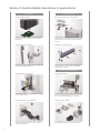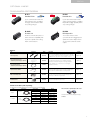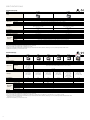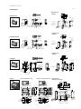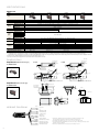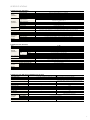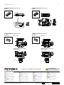
1
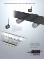
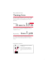
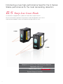
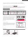
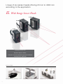
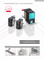
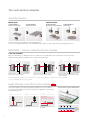
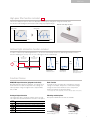
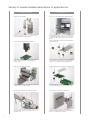
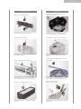
NEW
CMOS Multi-Function Analogue Laser Sensor
New Sensor Heads Released
“Stable Detection” Perfected
Laser Differentiation Displacement Sensor
Achieving the highest performance in its class
Excellent differentiation ability at reasonable prices
I- SERIES
I n t e l l i g e n t s en sor
IL Series
Excellent differentiation ability at reasonable prices
Sensor head
The sensor head has achieved tuning-less,
real-time control by adjusting the laser power,
shutter time and reception gain (amplification
factor) according to the changes in the target
colour or surface condition which hinder
stable detection. It ensures stable detection
in every application.
Multi-function amplifier (indicator)
All control specifications have been taken
into consideration. Output is compatible
with CC-Link, DeviceNet and EtherNet/IP in
addition to analogue, RS-232C and BCD. If
the application requires, this amplifier offers
height difference count filter and high pass
filter functions as standard, as well as addition/
subtraction calculation functions.
I- SERIES
I n t e l l i g e n t s en sor
2
Easy stable detection
Tuning-less
No need for tuning according to the type or surface condition
of detection targets. A dynamic range of x1.5 million for light
quantity control has achieved stable detection for various
applications.
3.5 m
Longest in its class
Variation
20 mm to
Sensor head lineup for every kind of applications. Wide
detection range is covered from a short distance to an ultralong distance of 3.5 m.
Repeatability
from
1 µm
The sensor heads offer various repeatability levels from 1 µm.
This enables a sufficient tolerance setting for applications
which could not be detected stably with presence-detection
sensors.
MEASUREMENT PRINCIPLE
These devices use the principle of triangulation
for measurement.
Target
When the position of targets is altered, the
position of the beam spot on the CMOS moves.
These devices measure the displacement of
targets by detecting the position of the beam
spot.
3
An abundance of head variations for all applications
Series
IL Series
CMOS Multi-function Analogue Laser Sensor
Head type
IL-S Sharp-Line Sensor Heads
IL-S025
Reference distance: 25 mm
Measurement Range: 10 mm
0
20
40
60
80
100
120
Measuring Range
from Head:
20 to 30 mm
Repeatability: 1 μm
Linearity: ±0.075% of F.S
IL Wide Range Sensor Heads
IL-S065
Reference distance: 65 mm
Measurement Range: 20 mm
IL-030
Reference distance: 30 mm
Measurement Range: 25 mm
Measuring Range
from Head:
55 to 75 mm
Repeatability: 2 μm
Linearity: ±0.05% of F.S
140
160
180
200
300
400
500
600
700
800
900
1000
1100
1200
1300
1400
1500
1600
1700
1800
1900
2000
2100
2200
2300
2400
2500
2600
2700
2800
2900
3000
3100
3200
3300
3400
3500
4
Equipped with three functions that enable maximum stability:
Super-Resolution Algorithm included
SCAN (Sensitive-laser Control Analyser) included
Sharp-Line Beam
Measuring Range
from Head:
20 to 45 mm
Repeatability: 1 μm
Linearity: ±0.1% of F.S
IL-065
Reference distance: 65 mm
Measurement Range: 50 mm
Measuring Range
from Head:
55 to 105 mm
Repeatability: 2 μm
Linearity: ±0.1% of F.S
IIL-100
Reference distance: 100 mm
Measurement Range: 55 mm
IL-300
Reference distance: 300 mm
Measurement Range: 290 mm
IL-600
IL-2000
Reference distance: 600 mm
Measurement Range: 800 mm
Intelligent Sensor
SERIES
NEW
Reference distance: 2000 mm
Measurement Range: 2500 mm
Measuring Range
from Head:
75 to 130 mm
Repeatability: 4 μm
Linearity: ±0.15% of F.S
Measuring Range
from Head:
160 to 450 mm
Repeatability: 30 μm
Linearity: ±0.25% of F.S
Measuring Range
from Head:
200 to 1000 mm
Repeatability: 50 μm
Linearity: ±0.25% of F.S
Measuring Range
from Head:
1000 to 3500 mm
Longest
in its class
3.5m
Repeatability: 100 μm
Linearity: ±0.16% of F.S
5
Introducing a new high-performance head for the IL Series
Stable performance for the most demanding detection
IL-S
Sharp-Line Sensor Heads
The transmitter is equipped with a cylindrical lens that enables sharp-line beams.
We have overhauled the signal processing inside the head and equipped the device with a
Super-Resolution Algorithm so that it is the highest-functioning model in its class.
IL-S025
IL-S065
Equipped with Industry First Super-Resolution Algorithm
Repeatability from 1 μm
Linearity ±0.05% of F.S.
Highest in its Class
Dynamic Range (x1.5 million)
6
Best in its class
IL- S Series
Equipped with three functions that enable maximum stability
Super-Resolution Algorithm included
Industry First
This algorithm identifies differences in CMOS received light waveforms generated by changes in surface conditions of target
workpiece and automatically processes waveforms in the best manner possible. Now, you can perform stable detection without
tuning, even on metal hairlines, plastic, rubber and other workpiece that has always been difficult to detect.
SUPER-RESOLUTION DEFINED
The shape of waveforms transmitted to CMOS depends on workpiece material and surface conditions. Before, stability also differed because the
same setting was used on different workpiece. The Super-Resolution Algorithm identifies the width of waveforms and automatically performs the
setting best suited for the shape of waveforms.
Ideal Waveform
Metal
Ceramic
Plastic
SCAN Function with Wide Dynamic Range
Irregular Refraction
Reduced power
Increased power
When the workpiece is
highly reflective
When the workpiece
is dark
SCAN (=Sensitive-laser Control Analyser)
The laser power, shutter time and reception gain on this device are
adjust in real-time in order to deliver stable detection faithfully for
all targets. We also developed a new digital circuit that enables a
dynamic range of x1.5 million, 2.5 times higher than past models.
Real-time controls that suit targets and their surface conditions enable
stable detection.
Reflection
Shutter time/power/gain
Sharp-Line Beam
CMOS
Laser beam transmitted to CMOS
IL-S
Light Intensity
KEYENCE’s original optical system pushes the beam diameter to the
limits (25 µm), and its sharpness enables the most excellent stability
in history. We have overhauled and optimised our optical system for
spot profiling for stability in applications that, until now, yielded very
erratic results.
Before
Sharpening the spot beam
diameter allows this device to
sharpen the waveform
transmitted to the CMOS. Now,
it is possible to see and
understand the peaks of
waveforms accurately.
CMOS
APPLICATION
Measuring the height of a chip after bonding
Height controls of a PC board
7
Lineup of six sensor heads offering 20 mm to 3500 mm
according to the application
IL
Wide Range Sensor Heads
IL-065
IL-100
IL-030
Repeatability from 1 μm
Dynamic range (x1 million)
Lineup of six sensor heads offering 20 mm to 3500 mm
according to the application
APPLICATION
Detecting the arm height through a view port
8
Detecting the height of a workpiece for a cutting machine
Detecting loose caps
IL Series
Excellent stability even in long range detection
Max.
3.5 m
NEW
IL-2000
Longest in its class
IL-600
IL-300
Excellent angle characteristics
Unaffected by target colours or materials
APPLICATION
Tension control of a sheet material
Detecting the level of molten aluminium
Detecting a remaining workpiece in a mould
9
The multi-function amplifier
Calculation Function
Addition mode
SETTING EXAMPLE 1
(thickness measurement)
Subtraction mode
SETTING EXAMPLE 2
(width measurement)
SETTING EXAMPLE 1
(Measurement of height difference)
SETTING EXAMPLE 2
(Measuring tilt)
Internal calculations are possible for all kinds of applications.
This device is equipped with an all-in-one add/subtract function that focuses PLC data and reduces programming hours.
NEW MODE – Thickness Calibration Function Included
3-step easy calibration
With conventional devices, calibration had to be conducted on every individual sensor head, however, the IL Series has a
dedicated mode that allows calibration to be completed in 3 simple steps.
1
2
3
Step
Step
Step
Bring the target close to one sensor head and input the
thickness data, then push the set button.
Bring the same target used in Step 1 close to the
opposing sensor head and push the set button.
Insert a target thicker than the target used in Step 2.
Input the thickness data. Then pushing the set button
completes calibration.
When bringing the target closer to the sensor head in Steps 1 and 2, you are compensating for the misalignments that occur during installation.
To set, you can begin with either one of the sensor heads.
Height difference count filter function included
NEW
This function identifies step edges automatically and delivers one-shot output for
each step. Create settings for count and seam detection applications easily, without
the programming hours.
1
Step
2
Step
Count the number of sheets of printed material
3
Step
Setting Complete
Identifies edges automatically and
delivers one-shot output for each step
Press the SET button for the lower step.
10
Press the SET button for the upper step.
Intermediary value threshold entered
automatically.
1st Stack
2nd Stack
3rd Stack
4th Stack
Threshold
Measured Value
GO Judgement
Output
IL Series
High pass filter function included
NEW
This function displays frequencies above the adjustable cutoff frequency and ignores changes below that cutoff.
It is effective for discarding smooth fluctuations and looking only at rapid changes.
Detection on the edge of a sheet
Measured Value
Measured Value
Filtered Waveform
Input Waveform
Time
Time
Ambient light elimination function included
In order to counteract any ambient light interference, the IL Series automatically activates the ambient light elimination function
when the sampling cycle is set to ‘2 ms’ or ‘5 ms’, reducing the effects of ambient light.
<A>
CMOS exposed to
laser emission
<B>
CMOS not exposed to
laser emission
—
=
(Minus)
(Equals)
Emission
Laser
Off
Sampling cycle
The CMOS
waveform of A
The CMOS
waveform of B
CMOS waveform
(difference)
Ambient light is present
Ambient light only
Waveform where the ambient
light has been removed
Function Choices
NPN/PNP Output Selection (judgement selection)
Bank Function
Both NPN and PNP outputs are supported. The outputs are set
the first time the user turns on the power. These settings can
subsequently be changed. Judgements are output as HIGH,
GO, or LOW.
The bank function can register up to four patterns of specific
settings.* For example, in response to a measurement target
changeover, this function allows the user to easily switch
between the patterns of registered settings.
* HIGH setting value, LOW setting value, shift value, analogue output scaling setting
Analogue Output Selection
Mounting method options
The following five types of analogue outputs can be selected.
The output is selected the first time the user turns on the power.
Both panel and DIN-rail mount units are available.
Setting
value
Description
Not output
Analogue output after the judgement value is converted to the range from 0 to 5 V.
Analogue output after the judgement value is converted to the range of ±5 V.
Analogue output after the judgement value is converted to the range from 1 to 5 V.
Analogue output after the judgement value is converted to the range from 4 to 20 mA.
The setting can be changed.
IL-1500/1550
IL-1000/1050
Panel mount type
DIN-rail mount type
11
Variety of heads enables abundance of applications
POSITIONING
12
THICKNESS
Robot arm positioning
Press processing thickness differentiation
Detect robot arm chuck precision on the X-, Y- and Z-axes. The long
range head enables detection from long distances.
Differentiate between steel plates or catch two sheets going through at
once with thickness differentiation in the press process. The long range
head enables differentiation from long distances, even for large-sized
pressing.
Vision system CCD height positioning
Thickness/width measurements of building
material boards
Position the vision system on the Z-axis during substrate inspection.
This device delivers stable detection, even for different target
workpiece materials.
Thickness and width can be simultaneously measured immediately after
the extrusion process. In addition, man-hours for setup and product
changeovers are reduced using the thickness calibration function.
Roll chuck position detection
Single/double-sheet substrate differentiation
Detect the position of roll chucks for film winding. Save a huge amount
of adjustment time, even for different equipment.
Differentiate single/double sheets when transferring substrates. This
device enables stable detection, even for different substrate material.
Position detection of a carton on a pallet
Sheet material thickness detection
The position of a carton on a pallet transferred by a palletizer is detected.
The detection is stable regardless of the changes in colours or the
inclination of cartons.
This device constantly monitors thickness differentiation of sheet
material. The multi-point head allows you to detect irregularities in the
thickness of edges and in the bodies of materials.
IL Series
SEAM/COUNT
Rubber sheet seam detection
HEIGHT
Detection of stage inclination prior to
furnace transportation
Detect seams in rubber sheets. Sensors above and below the workpieces
enable stable detection, even when the sheets flip-flop.
Calculates the inclination by measuring multiple points on the stage
prior to transferring to the furnace. Transferring the product after
correcting the inclination allows for consistent temperature control.
Detecting welding seams
Detecting the level of molten aluminium
Detect welding seams on steel plates. The Height Difference Count Filter
Function enables stable detection.
The ultra-long range type can be installed at a distance of 3500 mm
at maximum from the target, eliminating worries for the ambient
temperature.
Stacker counting & uneven checks
Differentiation of different types of plastic
components
The IL Series counts how many items are being transported along a
conveyer, in addition to the non-contact detection of uneven stacking in the
stacker. Reliable detection regardless of colour changes in the targets.
Reliable differentiation, even in highly variable small parts, using a highprecision sensor head. Even when the variety changes, external changeover
of up to 4 patterns is possible by setting items in the bank function.
Counting air conditioner filter sheets
Double-chip prevention/
chip presence detection
Count the number of air conditioner filter sheets. The High Pass Filter
Function enables stable detection, even for workpiece whose height is
not constant.
Check whether chips are present or not, or if two are present by mistake
during chip transfer. This device enables stable detection, even during
high-speed transfers.
13
Variety of heads enables abundance of applications
CONTROL
S H A P E -WA R P
Control marking height
Warpage detection in ceramic boards
Control the distance between the head of marking instruments and
workpiece. This device enables stable detection, even for different
target workpiece.
As the sensor head is compact, multiple point measurements of
small-scale boards are possible. By calculating the measurement data
externally, simultaneous measurements of positioning and warpage
are possible.
Control sheet roll diameter
Detect H-beam flange warp
Control feed speed and tension rolling with constant monitoring of sheet
diameter during rolling and unrolling processes.
Detect the warp of H-beam flanges at multiple points before using a
correction mechanism. Use a long range head for compatibility with
many different kinds of workpiece.
S T RO K E/ V I B R AT I O N
14
Control welding torch height
Press stroke control
Control the height of welding torches. Boost welding precision through
constant, exhaustive monitoring.
Proactively prevent press defects by constantly monitoring the amount of
press strokes and the bottom dead centre of presses. Use a long range
head to enable compatibility with large-sized pressing machine.
Height control of a hoop material
Traverser stroke control
The ultra-long range type can be installed at a distance of 3500 mm at
maximum from the target, which allows hoop control of steel plates or
sheet materials being transferred.
Prevent rolling disorders by controlling traverser strokes while measuring
the amount that bobbins roll to provide feedback to the instrument.
IL Series
OPTIONAL LINEUP
Communication Unit Variations
DL-EP1
EtherNet/IP Unit
NEW
NEW
DL-DN1
DeviceNet Unit
Cyclic communication makes live
data acquisition easy. In addition,
message communications allows
easy setting changes.
Cyclic I/O Communication makes
status monitoring simple. In addition,
Explicit Messaging capability allows
easy setting changes.
DL-RS1A
RS-232C Unit
DL-RB1A
BCD Output Unit
RS-232C communication protocol
allows universal compatibility with
any device capable of decoding
ASCII communications.
The measured value can be
synchronised with a trigger input or
updated via a timer. Output values
are synchronised with the strobe
output.
Optional
Type
Appearance
Model
Description
Weight
To connect an additional expansion unit, use the end units
to secure the display units on both ends. When connecting
additional units, be sure to use the end units. (2 pcs.)
End unit (Optional)
OP-26751
Panel front protection cover
[Included in panel mount type amplifier]
OP-87076
Panel mounting bracket
[Included in panel mount type amplifier]
OP-4122
Expansion cable: 300 mm
OP-35361
Extension cable used for panel mount type amplifier. Use
this cable if the standard cable is not long enough.
Approx. 10 g
DIN-rail mounting bracket
OP-60412
The mounting bracket is used when the expansion cable is
used to connect to the panel mount type display unit, in
which case a DIN rail is not provided.
Approx. 12 g
Mounting bracket
OP-87606
Special mounting bracket for IL-2000
Approx. 338 g
The panel front protection cover and panel mounting
bracket are included in the panel mount type amplifier.
If the supplied cover or bracket is lost or damaged,
purchase a new one.
Approx. 15 g
Approx. 6 g
Approx. 7 g
Sensor head cables (sold separately)
The cable does not come attached with the sensor head and must be purchased separately.
Type
Straight
L-shaped
Appearance
1 cable
included
1 cable
included
Cable length
2m
Model
Weight
OP-87056
Approx. 80 g
5m
OP-87057
Approx. 190 g
10 m
OP-87058
Approx. 360 g
20 m
OP-87059
Approx. 680 g
2m
OP-87660
Approx. 80 g
5m
OP-87661
Approx. 190 g
10 m
OP-87662
Approx. 360 g
20 m
OP-87663
Approx. 680 g
This connector is required if the cable is cut.
Connector used to connect to a display unit (2 pcs.)
OP-84338
15
S P E C I F I C AT I O N S
Sensor heads (IL-S)
Model
IL-S025
IL-S065
25 mm
20 to 30 mm
65 mm
55 to 75 mm
Shape
Reference distance
Measurement range
Red semiconductor laser, wavelength: 655 nm (visible light)
Class 2 laser product (FDA (CDRH) Part 1040.10 1. IEC 60825-1)
560 μW
Approx. 25 x 1200 μm
Approx. 55 x 1700 μm
±0.075% of F.S.
±0.05% of F.S.
(when used at 20 to 25 mm)
(when used at 55 to 65 mm)
Light source
Laser class
Output
Spot diameter (at reference distance)
Linearity 2. 3.
Repeatability Sampling cycle
Operation indicator
Temperature characteristics 3.
Enclosure rating
Ambient light 5.
Ambient temperature
Environmental
resistance
Relative humidity
Vibration
Pollution degree
Material
Weight
±0.1% of F.S.
(when used at 20 to 30 mm)
1 µm
4.
±0.075% of F.S.
(when used at 55 to 75 mm)
2 µm
0.33/1/2/5 ms (4 levels selectable)
Laser emission warning indicator: Green LED, Analogue range indicator: Orange LED, Reference distance indicator: Red/Green LED
0.03% of F.S./°C
0.02% of F.S./°C
IP67
Incandescent lamp: 10000 lux
-10 to +50°C (No condensation or freezing)
35 to 85% RH (No condensation)
10 to 55 Hz, 1.5 mm double amplitude in X, Y and Z directions, 2 hours respectively
3
Housing: PBT, Metal parts: 304 stainless steel, Packing: NBR, Lens cover: Glass, Cable: PVC
Approx. 60 g
Approx. 75 g
1. The laser classification for FDA (CDRH) is implemented based on IEC 60825-1 in accordance with the requirements of Laser Notice No. 50.
2. Value when the KEYENCE standard target (white diffuse object) is measured.
3. F.S. of each model is as follows: IL-S025: ±5 mm, IL-S065: ±10 mm
4. Value when the KEYENCE standard target (white diffuse object) is measured at the reference distance, sampling cycle of 1 ms, and average number of times of 128.
5. Value when the sampling cycle is set to 2 ms or 5 ms.
Sensor heads (IL)
Model
IL-030
IL-065
30 mm
20 to 45 mm
65 mm
55 to 105 mm
IL-100
IL-300
IL-600
NEW IL-2000
Shape
Reference distance
Measurement range
Light source
Laser class
Output
Spot diameter (at reference distance)
Linearity 2. 3.
Repeatability 4.
Sampling cycle
Operation indicator
Temperature characteristics 3.
Enclosure rating
Ambient light 5.
Ambient temperature
Environmental
resistance
Relative humidity
Vibration
Pollution degree
Material
Weight
100 mm
300 mm
600 mm
75 to 130 mm
160 to 450 mm
200 to 1000 mm
Red semiconductor laser, wavelength: 655 nm (visible light)
Class 1 laser product
(FDA (CDRH)
Part 1040.10 1.
IEC 60825-1)
220 μW
Approx. 200 x 750 μm
Class 2 laser product (FDA (CDRH) Part 1040.10 1., IEC 60825-1)
Approx. 550 x 1750 μm
±0.1% of F.S.
(when used at
25 to 35 mm)
±0.1% of F.S.
(when used at
55 to 75 mm)
1 µm
2 µm
560 μW
Approx. 400 x 1350 μm
Approx. ø500 μm
±0.15% of F.S.
(when used at
80 to 120 mm)
±0.25% of F.S.
(when used at
160 to 440 mm)
Approx. ø1600 μm
Approx. 1400 x 7000 μm
±0.25% of F.S.
(when used at
200 to 600 mm)
±0.5% of F.S.
(when used at
200 to 1000 mm)
±0.16% of F.S.
(when used at
1000 to 3500 mm)
4 µm
30 µm
50 µm
0.33/1/2/5 ms (4 levels selectable)
Laser emission warning indicator: Green LED, Analogue range indicator: Orange LED, Reference distance indicator: Red/Green LED
0.05% of F.S./°C
0.06% of F.S./°C
0.06% of F.S./°C
0.08% of F.S./°C
IP67
Incandescent lamp: 5000 lux
Incandescent lamp: 7500 lux
Incandescent lamp: 5000 lux
-10 to +50°C (No condensation or freezing)
35 to 85% RH (No condensation)
10 to 55 Hz, 1.5 mm double amplitude in X, Y and Z directions, 2 hours respectively
3
Housing: PBT, Metal parts: 304 stainless steel, Packing: NBR, Lens cover: Glass, Cable: PVC
Approx. 60 g
Approx. 75 g
Approx. 135 g
1. The laser classification for FDA (CDRH) is implemented based on IEC 60825-1 in accordance with the requirements of Laser Notice No. 50.
2. Value when the KEYENCE standard target (white diffuse object) is measured.
3. F.S. of each model is as follows: IL-030: ±5 mm, IL-065: ±10 mm, IL-100: ±20 mm, IL-300: ±140 mm, IL-600: ±400 mm, IL-2000: +1000 mm to -1500 mm
4. Value when the KEYENCE standard target (white diffuse object) is measured at the reference distance, sampling cycle of 1 ms, and average number of measurements of 128.
(2 ms for IL-300/600, 5 ms for IL-2000)
5. Value when the sampling cycle is set to 2 ms or 5 ms.
16
2000 mm
1000 to 3500 mm
100 µm
0.016% of F.S./°C
Incandescent lamp: 10000 lux
Approx. 350 g
DIMENSIONS
Unit : mm
Sensor heads
Mounting bracket
(supplied)
4.8
IL-S025/IL-030
4.8
12
22.6
22.6
9.1
22.6
Centre
of 24.8
38.3
received light
Centre of
Centre
of light
emitted
received light
0.648.5
12
2-ø3.5
42.1(mounting hole)
11.7
33.5
37.9
11.7
(min. 5)
33.5
37.9
11.7
9.5
9.4
ø9
ø4.8 cable length 160
Tip (26)
M8 connector
ø9
ø4.8 cable length 160
(26)
Tip
M8 connector
42.1
(min. 5)
33.5
37.9
ø9
9.5
9.4
9.5
9.4
ø4.8 cable length 160
Tip M8 connector
Supplied screw (2 pcs.)
Material:
SUS304
M3, P=0.5,
L=30
Material:t=2.0
SUS
60
Supplied
screw (2 pcs.)
Material:
SUS304
M3, P=0.5,
t=2.0L=30
20
Material: SUS
Supplied screw (2 pcs.)
M3, P=0.5, L=30
Material: SUS
20
60
(min. 5)
24.1
23.2
42.3
11.6
23.2
Centre42.3
of
received light
23.2
Centre
42.3oflight
emitted
Centre
of
received light
11.6
24.1
24.1
11.6
10.5
Centre
Centre
of of
emittedlight
light
received
10.5
Centre of
emitted light
10.5
34.7
52.5
0.6
15.4
0.652.5
15.4
11.6
3.6
52.5
15.4
Reference surface
for distance detection
11.6
3.6
2-ø3.5
(mounting hole)
3.2
3.2
2-ø3.5
46.1(mounting hole)
11.7
38.5
46.1
42.8
Reference surface
for distance detection
9.4
ø9
12 4.8
3.5
6.5
ø4.8 cable length 160
(26)
Tip M8 connector
9.5
Supplied screw (2 pcs.)
Material:
SUS304
M3, P=0.5,
L=30
t=2.0
Material:
SUS
62
9.4
62
3.5
IL-300/600
27.2
16.4
20.5
5.5˚
27.2
55.8
20.5 16.4
55.8
Centre of
20.5
received light
Centre of
55.8
emitted
light
Centre of
13.6
received light
Centre of
emitted
Centre
of light
received light
13.6
Centre of
emitted light
13.6
45
4.5
66
4.5
3.6
20.8
13
15.5
66
50.7
3.6
Reference surface
13
for distance detection
(26)
15.5
50.7
13
Reference surface
for distance detection
15.5
11.4
11.6
ø9
Material: SUS304
t=2.0
53.6
6
42
32.4
15.5
42
32.4
15.5
4.5
5.3
5.3
4.5
Material: SUS304
t=2.0
4.5
ø4.5
2× M4 P=0.7
Material: SUS304
t=2.0
ø4.5
57
ø4.5 69.8
57
Material:2×SUS304
M4 P=0.7
t=2.0
59.1
67.1
2× M4 P=0.7
59.1
69.8
67.1
8
57
3.5°
4.5
59.1
69.8
67.1
8
8°
22
53.6
5.3
42
32.4
15.5
4.5
47.6
47.6
6
57.2
4.5
76
6
46.1
8°
22
4.5 3.5°
8
8°
22
11.6
(min. 5)
50.7
11.4
11.6 11.4
(min. 5)
(26)
76
Material: SUS304
t=2.0
46.1
9.1 9.1 18.5
76
Material: SUS304
t=2.0
ø4.8 cable lengthø9160
Tip M8 connector
(26)
ø4.8 cable length 160
57
(min.Tip5)M8 connector ø9
57
66
.5
9.14˚ 9.1 18.5
4.5
4.5
ø4.8 cablehole)
length 160
2-ø4.4 (mounting
57
Tip M8 connector
4.5
45
0.6
3.6
20.8
4.5
45
0.6
20.8
2-M3 P=0.5
Material: SUS304
53.6
t=1.5
47.6
2-M3 P=0.5
57.2
4˚
12
2-ø4.4 (mounting hole)
2-M3 P=0.5
Material: SUS304
t=1.5
.5
ø 3 3.5
3.8
9.1 9.1 18.5
7.5
4.5
123.8
7.5
2-ø4.4 (mounting hole)
0.6
12
Material: SUS304
t=1.5
4.8 3.5
ø3
4˚
5.5˚
20
6
57.2
3.5
5.5˚
Mounting bracket
(supplied)
4.5
6
.5
ø 3 46.1
11.7
3.5
3.8
7.5
27.2
16.4
43.7 49.7
3.5
4.8
22.1
20
(min. 5)
6
55.2
6.7 15
22.1
31.3
11.7
3.5
9.5
ø4.8 cable length 160
Tip M8 connector
55.2
4.8
12
Supplied screw (2 pcs.) 20
M3, P=0.5, L=30
Material: SUS
43.7 49.7
42.1
6.7 15
31.3
6.7 15
4.8
12
22.1
6.5
3.5
11.7
31.3
62
9.5
2-M3 P=0.5
.5
42.1
2.5˚
2.54.8
˚
6.5
Supplied screw (2 pcs.)
M3, P=0.5,
L=30
Material:
SUS304
Material:t=2.0
SUS
9.4
ø9
ø4.8 cable length 160
Tip
(26)M8 connector
(min.11.7
5)
38.5
42.8
11.7
(min. 5)
38.5
42.8
Reference surface
11.6
for distance detection
ø9
2-M3 P=0.5
Material: SUS304
43.7
t=1.549.7
55.2
3.5 2.5˚
2.5˚
Material: SUS304
t=2.0
3.2
2-ø3.5
(mounting hole)
46.1
3.2
(26)
3.2
34.7
3.6
3.2
ø3
2.5
3.52.5˚
˚
60
2-M3 P=0.5
Material: SUS304
t=1.5
.5
ø 342.1
11.7
3.5
Material: SUS304
t=1.5
3.5
.5
ø3
30
11.7
18.3
20
34.7
0.6
4.8
3.5
4.8
3.5
11.7
30
18.3
3.5
Material: SUS304
t=2.0
Mounting bracket
(supplied)
IL-S065/IL-065/100
6.5
12
3.2
2-ø3.5
(mounting hole)
42.1
(26)
3.2
3.2
29.7
Reference surface
9.1 distance detection
for
Reference surface
for distance detection
3.2
29.7
3.6
Reference surface48.5
13.7
for9.1
distance
detection
3.6
9.5
9.5
3.6
2-ø3.5
(mounting hole)
4.8
3.5
6.6
13.8
3.5
6.6
30
13.8
18.3
6.5
4.8
3.2
48.5
0.6
13.7
9.1 13.7
9.1
9.5
Centre of
24.8
38.3 light
emitted
Centre
of
received light
Centre of
emitted light
29.7
0.6
9.1
38.3 24.8
3.2
6.6
13.8
6.5
3.5°
Reference surface
for distance detection
IL-2000
When a straight cable is used
When an L-shaped cable is used
Mounting bracket
OP-87606 (sold separately)
55
25
15
22.9
22.9
69
5.5
20
69
2 × ø6(mounting hole)
2 × ø6(mounting hole)
M8 connector
50
28
M8 connector
5.5
44
(10)
82
59.5
5.5
54.5
77
88
3.2
47.8
Reference surface
for distance detection
5.5
24
54.5
77
88
3.2
47.8
Reference surface
for distance detection
Centre of
emitted light
76
26
18.4
44.8
18.4
110
100
77 87
7°
7°
43
5.5
5.5
24
42.2
Centre of
received light
42.2
Centre of
received light
18.4
44.8
18.4
10
95
82
59.5
Centre of
emitted light
76
26
2-ø5.5
103.5
50
SUS304
t=3.0
7° 7°
10
75
2-M5 P=0.8
SUS304
t=3.0
100
17
S P E C I F I C AT I O N S
Amplifier unit
IL-1000
Model
IL-1500
IL-1050
IL-1550
Panel mount
DIN-rail mount
Shape
Type
Main unit/expansion unit
Head compatibility
Minimum displayable unit
Display
DIN-rail mount
Expansion unit
Compatible
IL-S025/IL-030: 1 μm, IL-S065/IL-065/IL-100: 2 μm, IL-300: 10 μm, IL-600: 50 μm, IL-2000: 100 μm
IL-S025/IL-030/IL-S065/IL-065/IL-100: ±99.999 mm to ±99 mm (4 levels selectable), IL-300/IL-600: ±999.99 mm to ±999 mm (3 levels selectable),
IL-2000: ±9999.9 mm to ±9999 mm (2 levels selectable)
Approx. 10 times/sec.
±5 V, 1 to 5 V, 0 to 5 V Output impedance 100 Ω
None
4 to 20 mA Maximum load resistance of 350 Ω
Display range
Display rate
Analogue voltage output 1.
Analogue current output 1.
Bank switch input
Zero-shift input
Control
Stop emission input
input 2.
Timing input
Reset input
Judgement output
Control
3.
output
Alarm output
Power voltage 4.
Current
Power consumption
Ambient temperature
Environmental Ambient humidity
resistance
Vibration
Pollution degree
Material
Weight (including attachments)
Panel mount
Main unit
Non-voltage input
Open collector output (NPN, PNP changeover possible/N.O., N.C. changeover possible)
Open collector output (NPN, PNP changeover possible/N.C.)
10 to 30 VDC ripple (P-P) 10% included, Class 2or LPS*5
Supplied by main unit
2300 mW or less (at 30 V: 77 mA or less)
2500 mW or less (at 30 V: 84 mA or less)
2000 mW or less (at 30 V: 67 mA or less)
2200 mW or less (at 30 V: 74 mA or less)
-10 to +50°C (No condensation or freezing)
35 to 85% RH (No condensation)
10 to 55 Hz Double amplitude 1.5 mm XYZ each axis: 2 hours
2
Case / Front sheet: Polycarbonate; Key tops: Polyacetel; Cable: PVC
Approx. 150 g
Approx. 170 g
Approx. 140 g
Approx. 160 g
1. Select and use one of ±5 V, 1 to 5 V, 0 to 5 V or 4 to 20 mA. 2. Assign an input of your choice to the 4 external input lines before using.
3. – The NPN open collector rated output is: 50 mA max./ch (20 mA when adding an expansion unit) less than 30 V, residual voltage less than 1 V (less than 1.5 V when adding over 6 units including the main unit)
– The PNP open collector rated output is: 50 mA max./ch (20 mA/ch when adding expansion units), less than power voltage, and less than 2 V residual voltage (less than 2.5 V when adding over 6 units including the main unit)
4. If there are over 6 additional expansion units, please use a power voltage of 20 to 30 V.
5. Use Class 2 or LPS power supply with the overcurrent protection device rated 2.5 A or less.
Unit : mm
DIMENSIONS
Amplifier unit (DIN-rail mount type)
Cable diameter ø4.7
Cable length 2 m
IL-1000
IL-1000/IL-1050
(min.15)
21.6
20
(min.15)
44.7
35.4
20
Cable diameter ø4.7
Cable length 2 m
21.6
35.4
17.6
(min.15)
76.3
(min.15)
47.6
27.4
27.4
76
76
White
Grey
Green
Light
blue 1.
Orange
2.
Shield 2.
Pink
3.
Yellow 3.
Pink/purple 3.
Purple
18
3.
35.4
° MA
X
When cover is open
max.109.2
When cover is open
max.109.2
20
21.6
35.4
17.6
17.6
(min.15)
76.3
(min.15)
19.1
+0.6
45 -0
Panel
thickness
1 to 6
Panel thickness
1 to 6
9.7
19.1
9.7
44.7
9.7
17.6
22.4
9.7
min.85
min.85
44.7
19.1
+0.6
45 -0
X=48 ×
X=48 X×
(number of amplifiers) -3
(number of amplifiers) -3
X
17.6
Black
(min.15)
21.6
(3.4)
135
17.4
76.3
47.6
48
48
Blue 1.
(min.15)
12.4
19.1
Brown 1.
20
37.4
X
28.3
Cable diameter ø4.8
12.4
WIRING DIAGRAM
42.4
° MA
18.5
28.3
15.3
Cable diameter ø4.8
37.1
37.1
1335
3
When cover is open
max.109.2
17.4
37.4
42.4
17.6
(1.9)
(3.4) diameter ø4.8
Cable
Cable diameter ø4.7
Cable length 2 m
44.7
4
15.3
X
°MA
When cover is open
max.109.2
76.3
Cable diameter ø4.7
Cable length 2 m
135
17.4
42.4 37.4
17.4
42.4 37.4
18.5
(1.9)
Cable diameter ø4.8
X
°MA
1353
3
4
8.9
8.9
Cable diameter ø4.8
Cable diameter ø4.8
IL-1500/IL-1550
28.3
8.9
8.9
Amplifier unit (Panel mount type)
Cable diameter ø4.7
Cable length 2 m
IL-1050
18.5
28.3
18.5
Cable diameter ø4.7
Cable length 2 m
22.4
45 +0.6
-0
45 +0.6
-0
+0.6
45 -0
+0.6
45 -0
10 to 30 VDC 4.
0V
HIGH judgement output
LOW judgement output
GO judgement output
Alarm output
Analogue output +
Analogue output GND
External input 1 (zero shift input)
External input 2 (reset input)
External input 3 (timing input)
External input 4 (not used)
1. The brown, blue, and light blue cables are not provided in a IL-1050/IL-1550 unit (expansion unit).
The power is supplied to the expansion unit from the IL-1000/IL-1500 unit (main unit).
2. For an analogue output, OFF (not used), 0 to 5 V, ±5 V, 1 to 5 V, or 4 to 20 mA can be selected.
3. For an external input, bank A input, bank B input, laser emission stop input, or OFF (not used) can also be selected.
For details, refer to the User’s Manual.
4. If there are over 6 additional expansion units, please use a power voltage of 20 to 30 V.
S P E C I F I C AT I O N S
Communication unit (EtherNet/IP)
DL-EP1
IEEE802.3 (10BASE-T)/IEEE802.3u (100BASE-TX)
10Mbps (10BASE-T)/100Mbps (100BASE-TX)
STP cable or Category 3 or higher UTP cable (10BASE-T)/STP cable or Category 5 or higher UTP cable (100BASE-TX)
100 m (Distance between DL-EP1 and Ethernet switch)
4 (10BASE-T)/2 (100BASE-TX)
Cyclic communication (Implicit messaging)
Message communication (Explicit messaging)
Compatible with UCMM and Class 3
64
0.5 to 10000 ms (0.5 ms unit)
Model
Ethernet
specifications
Compliant standards
Transmission rate
Transmission medium
Maximum cable length
Maximum number of connectable hubs
Compatible functions
EtherNet/IP
specifications
Sensor connection
specifications
Number of connections
RPI (Transmission cycle)
Tolerable communication bandwidth
for cyclic communication
Conformance test
Connectable sensors
Number of connectable
sensor units
Indicators
Power voltage
Power consumption
Environmental
resistance
Operating ambient air temperature
Operating ambient air humidity
Vibration resistance
Pollution degree
Materials
Weight
6000pps
Compatible with Version A7
Sensor amplifiers with D-bus support 1.
Up to 8 units
Link/activity indicator (LINK/ACT): Green LED, Module status indicator (MS): 2-colour (green/red) LED,
Network status indicator (NS): 2-colour (green/red) LED, Sensor communication indicator (D-bus) 2-colour (green/red) LED
Including 20 to 30 VDC ripple (p-p) 10% (This voltage is supplied from the connected sensor amplifier)
1500 mW or less (at 30 V 50 mA max)
-20 to +55°C (no freezing)
35 to 85% RH (no condensation)
10 to 55 Hz compound amplitude 1.5 mm, 2 hours each in X, Y, Z directions
2
Main unit case: Polycarbonate
Approx. 70 g
Communication unit (DeviceNet)
Model
Communication method
Compliant functions
Address setting
Baud rate (automatically switched)
DeviceNet
500 kbps
specifications
Maximum cable
250 kbps
length
125 kbps
Network power supply
Sensor connection Connectable sensors
specifications
Number of connectable sensor units
Indicators
Power voltage
Power consumption
Environmental
resistance
Operating ambient temperature
Operating ambient humidity
Vibration resistance
Pollution degree
Materials
Weight (including connectors)
DL-DN1
DeviceNet compliant
Remote I/O communication (polling) Explicit messaging
0 to 63 (PGM compatible).
500 kbps/250 kbps/125 kbps
100 m for thick cable; 100 m for thin cable
250 m for thick cable; 100 m for thin cable
500 m for thick cable; 100 m for thin cable
11 to 25 VDC (supplied from DeviceNet communication power supply)
Sensor amplifiers with D-bus support 1.
8 units max.
Network status indicator: 2-colour (green/red) LED, Module status indicator: 2-colour (green/red) LED,
Sensor communication indicator: 2-colour (green/red) LED
20 to 30 VDC, including ripple (P-P) 10% (supplied from the connected sensor amplifiers)
660 mW or less (at 30 V, 22 mA max.)
-20 to +55°C (no freezing)
35 to 85% RH (no condensation)
10 to 55 Hz, compound amplitude 1.5 mm, 2 hours each in X, Y, Z directions
2
Main unit case and dust cover: Polycarbonate, DeviceNet connector: Polyamide (plug), PUT (socket)
Approx. 80 g
1. “D-bus” is the name of KEYENCE’s wiring-saving system for sensor amplifiers.
Communication unit (BCD output: DL-RB1A/RS-232C: DL-RS1A)
Model
Power supply voltage
Power consumption
Number of connectable sensor amplifiers
DL-RB1A
DL-RS1A
20 to 30 VDC, including ripple, Ripple (P-P): 10% max. Class 2 (Supplied via connected sensor amplifier)
27 mA max.
25 mA max.
Up to 8 units (including main unit)
Alarm indicator lamp (red), Power indicator lamp (green)
Communication indicator lamp (green × 2), Alarm indicator lamp (red),
Power indicator lamp (green)
Communication method
Synchronisation method
Transmission code
Baud rate
Data bit length
Parity check
Stop bit length
-
Full duplex
Start-stop
ASCII
2400/4800/9600/19200/38400 bps selectable (Factory-setting: 9600 bps)
8 bits/7 bits selectable (Factory-setting: 8 bits)
None/Even/Odd selectable (Factory-setting: None)
1 bit
Data delimiter
-
Data reception: automatically recognises CR or CR+LF
Data transmission: Fixed to CR+LF
Indicator
Environment
resistance
Material
Weight
Ambient temperature
Ambient humidity
Vibration resistance
-10 to +55°C
35 to 85%RH (No condensation)
10 to 55 Hz Double amplitude 1.5 mm XYZ each axis: 2 hours
Case/Polycarbonate
Approx. 46 g
Approx. 53 g
19
Unit : mm
DIMENSIONS
(42.5)
38.1
Communication unit (EtherNet/IP Unit)
Communication unit (DeviceNet Unit)
DL-EP1
DL-DN1
43.5
35.4
94.5
25.6
29.4
29.4
49.5
35.5
125
9.6
°m
2.4
When cover is
opened:
58.3 max.
(42.5)
5.4
ax.
56.3
37.7
(42.2)
38.1
24.1
43.5
35.4
78.2
35.4
94.5
29.4
Communication unit (BCD Output Unit)
DL-RB1A
DL-RS1A
DIN-rail mount 49.5
125
Communication unit (RS-232C Unit)
35.5
9.6
°m
ax.
2.4
When cover is
opened:
58.3 max.
DIN-rail mount
5.4
22.5
22.5
56.3
37.7
(42.2)
53.4
34-pin MIL connector
37.1 24.1
(57.8)
(48.2) 37.2
35.4
78.2
43.8
35.4
70
21.1
35.4
70
21.1
When the mounting bracket is attached
OP-60412 (Optional)
When the mounting bracket is attached
OP-60412 (Optional)
53.4
51.3
60.9
37.1
37.2
43.8
31.4
70
15
2-ø3.4
31.4
2 - (4.4 × 3.4)
2-ø3.4
15
2 - (4.4 × 3.4)
22.5
22.5
15
Material : SPCC Steel
70
15
28.5
35.5
Material : SPCC Steel
Please visit:
www.keyence.com
28.5
35.5
SAFETY INFORMATION
Please read the instruction manual carefully in
order to safely operate any KEYENCE product.
KEYENCE CORPORATION
1-3-14, Higashi-Nakajima, Higashi-Yodogawa-ku, Osaka, 533-8555, Japan
AUSTRIA
Phone: +43 22 36-3782 66-0 Fax: +43 22 36-3782 66-30
BELGIUM
Phone: +32 1 528 1222 Fax: +32 1 520 1623
BRAZIL
Phone: +55-11-3045-4011 Fax: +55-11-3045-5219
CANADA
Phone: +1-905-366-7655 Fax: +1-905-366-1122
CHINA
Phone: +86-21-68757500 Fax: +86-21-68757550
CZECH REPUBLIC
Phone: +420 222 191 483 Fax: +420 222 191 505
FRANCE
Phone: +33 1 56 37 78 00 Fax: +33 1 56 37 78 01
Phone: +81-6-6379-2211
GERMANY
Phone: +49 61 02 36 89-0 Fax: +49 61 02 36 89-100
HONG KONG
Phone: +852-3104-1010 Fax: +852-3104-1080
HUNGARY
Phone: +36 1 802 73 60 Fax: +36 1 802 73 61
INDIA
Phone: +91-44-4963-0900 Fax: +91-44-4963-0901
ITALY
Phone: +39-02-6688220 Fax: +39-02-66825099
JAPAN
Phone: +81-6-6379-2211 Fax: +81-6-6379-2131
KOREA
Phone: +82-31-789-4300 Fax: +82-31-789-4301
MALAYSIA
Phone: +60-3-2092-2211 Fax: +60-3-2092-2131
MEXICO
Phone: +52-81-8220-7900 Fax: +52-81-8220-9097
NETHERLANDS
Phone: +31 40 20 66 100 Fax: +31 40 20 66 112
POLAND
Phone: +48 71 36861 60 Fax: +48 71 36861 62
ROMANIA
Phone: +40 269-232-808 Fax: +40 269-232-808
SINGAPORE
Phone: +65-6392-1011 Fax: +65-6392-5055
SLOVAKIA
Phone: +421 2 5939 6461 Fax: +421 2 5939 6200
SLOVENIA
Phone: +386 1-4701-666 Fax: +386 1-4701-699
SWITZERLAND
Phone: +41 43-45577 30 Fax: +41 43-45577 40
TAIWAN
Phone: +886-2-2718-8700 Fax: +886-2-2718-8711
THAILAND
Phone: +66-2-369-2777 Fax: +66-2-369-2775
UK & IRELAND
Phone: +44-1908-696900 Fax: +44-1908-696777
USA
Phone: +1-201-930-0100 Fax: +1-201-930-0099
WW1-1062
The information in this publication is based on KEYENCE’s internal research/evaluation at the time of release and is subject to change without notice.
Copyright (c) 2012 KEYENCE CORPORATION. All rights reserved.
IL-WW-C3-GB 1102-1 600B40 Printed in Japan
*
6
0
0
B
4
0
*