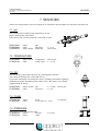
1
i-Control
for
In Situ sterilizable 140L Bioreactor
HARDWARE MANUAL
Project 48560 (140L Pilot System), UC Davis
June 2009
CONTENTS
HARDWARE MANUAL
i-Control for In Situ sterilizable Bioreactors
June 2009
TABLE OF CONTENTS
1 2 3 4 5 6 7 2
GENERAL SAFETY ................................................................................................................................ 4 1.1 Symbols............................................................................................................................................ 4 1.2 Safety class I equipment................................................................................................................... 5 140L Pilot System ..................................................................................................................................... 7 THE i-CONTROL ..................................................................................................................................... 8 3.1 VIEWS ............................................................................................................................................. 8 3.1.1 Front and rear view............................................................................................................. 8 3.1.2 Bottom view ....................................................................................................................... 9 3.1.3 Inside left view ................................................................................................................. 10 3.1.4 Fuse specifications ........................................................................................................... 11 3.1.5 Electirical Connections..................................................................................................... 12 3.1.6 Sensor & I/O connections................................................................................................. 12 3.1.7 Pneumatic i/o connections ................................................................................................ 13 3.1.8 Gas inlets and Outlet ........................................................................................................ 14 3.1.9 Mains connection and Power Section .............................................................................. 14 3.2 ENVIRONMENTAL CONDITIONS ............................................................................................ 15 3.3 CLEANING INSTRUCTIONS...................................................................................................... 15 ACTUATORS ......................................................................................................................................... 16 4.1 GAS SUPPLY SECTION .............................................................................................................. 16 4.2 ACTUATORS FOR TEMPERATURE CONTROL ..................................................................... 17 4.3 PUMPS AND TUBING ................................................................................................................. 18 140L BIOREACTOR .............................................................................................................................. 21 AUXILIARIES ........................................................................................................................................ 22 6.1 AGITATION .................................................................................................................................. 22 6.1.1 Magnetic Bottom Stirrer ................................................................................................... 22 6.1.2 Impellers and baffles ........................................................................................................ 22 6.1.3 Motor and Controller ........................................................................................................ 23 6.1.4 Maintenance ..................................................................................................................... 23 6.2 AERATION ................................................................................................................................... 24 6.2.1 Gas Inlet Filter Assembly ................................................................................................. 24 6.2.2 Spargers and Overlays ...................................................................................................... 25 6.2.3 Gas Outlet System ............................................................................................................ 26 6.3 SAMPLE VALVE AND DRAIN .................................................................................................. 27 6.3.1 Sampling System .............................................................................................................. 27 6.3.2 Contained Bottom Drain .................................................................................................. 27 6.3.3 Bio Waste ......................................................................................................................... 28 6.4 ADDITION .................................................................................................................................... 28 6.4.1 Push Valve Assembly ....................................................................................................... 28 6.4.2 Contained Addition Assembly ......................................................................................... 28 6.5 SAFETY DEVICES ....................................................................................................................... 29 6.5.1 Pressure Gauge ................................................................................................................. 29 6.5.2 Pressure Gauge and Relief Valve for Jacket .................................................................... 29 6.5.3 Rupture Disk and Discharge Pipe .................................................................................... 29 6.6 OTHER AUXILIARIES ................................................................................................................ 30 6.6.1 Illumination ...................................................................................................................... 30 6.6.2 Blind Stoppers .................................................................................................................. 30 SENSORS................................................................................................................................................ 31 7.1 pH ................................................................................................................................................... 31 7.2 Temperature ................................................................................................................................... 31 7.3 DO .................................................................................................................................................. 31 HARDWARE MANUAL
i-Control for In Situ sterilizable Bioreactor
June 2009
CONTENTS
7.4 FOAM ............................................................................................................................................ 31 7.5 Pressure .......................................................................................................................................... 31 EU DECLARATION OF CONFORMITY.................................................................................................... 32 3
HARDWARE MANUAL
SAFETY
i-Control for In Situ sterilizable Bioreactors
June 2009
1 GENERAL SAFETY
1.1 SYMBOLS
The following symbols are used on the equipment and in this manual.
WARNING
Risk of personal injury or danger to life.
WARNING
Risk of electrical shock hazard.
WARNING
Risk of physical hand injury
WARNING
Risk of physical hand injury.
CAUTION
Risk of damage to the equipment.
Additional information
4
HARDWARE MANUAL
i-Control for In Situ sterilizable Bioreactors
June 2009
SAFETY
1.2 SAFETY CLASS I EQUIPMENT
GENERAL
•
•
•
•
This set of equipment has been designed in accordance with EN61010-1 "Safety Requirements for
Electrical Equipment for Measurement, Control and Laboratory Use", and has been supplied in a safe
condition.
The Hardware manual contains information and warnings, which have to be followed by the user to
ensure safe installation, operation and to retain the equipment in safe condition.
Before switching on the equipment, make sure that it is set to the line voltage.
This equipment is designed for bioprocess control; it must not be used for other purposes!
WARNING
Risk of electrical shock hazard.
•
•
•
•
•
Any interruption of the protective conductor inside or outside the apparatus or disconnection of the
protective conductor terminal will make the apparatus dangerous. Intentional interruption is prohibited.
Capacitors inside the apparatus may still be charged, even if the apparatus has been disconnected from
all voltage sources.
Any adjustment, maintenance and repair of the opened apparatus under voltage must be avoided as far as
possible and, if inevitable, the activities must only be carried out by qualified personnel.
Make sure that only fuses with the required rated current and of the specified type (IEC 127) are used
for replacement. The use of makeshift fuses and the short-circuiting of fuse holders are prohibited.
It is not permitted to connect equipment to the i-Control or the bioreactor without the qualification of
double isolation or without the SELV (Separated Extra Low Voltage) qualification.
WARNING
Risk of physical hand injury caused by pumps.
•
•
•
In most cases, one or more pumps are installed in the i-Control.
According to the European Community legislation on machinery, a pump drive is a machine with
potential hazard. Only apply these drives with the pump heads and tubing that are described in this
manual (chapter: pumps)!
Switch off the power of the pump drive before replacing any tubes or pump heads.
CAUTION
Risk of damage to the equipment.
•
•
•
Do not use the tubing pump drives for other purposes than displacement of fluids (or gas).
Application of damaged tubes may result in fluid leaking into the pump drive.
Verify the tube quality inside the pump head before every fermentation run.
5
HARDWARE MANUAL
SAFETY
i-Control for In Situ sterilizable Bioreactors
June 2009
Additional information
•
•
•
6
Do not apply an Earth Leakage Circuit Breaker in the power supply of the Applikon control equipment
(in an industrial environment or laboratory, an earth leakage circuit breaker is not mandatory).
Because of the built-in main supply filters, an Earth Leakage Circuit Breaker may be activated. As a
result, the power will be switched off!
Additional electrical protection can be realized by installing a separation transformer between the mains
and the control equipment.
HARDWARE MANUAL
i-Control for In Situ sterilizable Bioreactors
June 2009
BIOREACTOR
2 140L PILOT SYSTEM
The 140L Pilot System consist of the following parts:
•
•
•
•
An In Situ sterilizable Bioreactor with the appropriate auxiliaries, like a stirrer assembly, baffles,
sensors, an aeration assembly, etc.
A wet part for temperature control and steam sterilization.
A Bioconsole (the i-Control) for measurement and control of process variables (pH, temperature, DO,
level, pressure, and stirrer speed) with corresponding controller outputs in order to keep process
conditions at set-point.
The isometric representation (given below) shows the main components of the 140L Pilot System on a
skid
7
HARDWARE MANUAL
THE i-CONTROL
i-Control for In Situ sterilizable Bioreactors
June 2009
3 THE i-CONTROL
The i-Control combines and supports actuators like pumps and valves in order to optimize the use of limited
bench space. A survey of the i-Control for the 140L bioreactor is presented in the following sections.
3.1 VIEWS
3.1.1 FRONT AND REAR VIEW
Figure: The front and rear exterior of the i-Control cabinet:
8
HARDWARE MANUAL
i-Control for In Situ sterilizable Bioreactors
June 2009
THE i-CONTROL
3.1.2 BOTTOM VIEW
Figure: Bottom view. Note the MFC max 1000L/min is located on the bottom panel while the remaining
MFCs are on the inside
9
HARDWARE MANUAL
THE i-CONTROL
i-Control for In Situ sterilizable Bioreactors
June 2009
3.1.3 INSIDE LEFT VIEW
Fuses (F1, F2, F3)
Stirrer motor
controller
Power
section
Fuses
(F5, F8, F9)
Fuses
(F10, F13, F14)
I/O
section
Solenoid gas
valves
PLC
MFCs
Solenoid valves
manifold
Figure: In side left view with door open
10
HARDWARE MANUAL
THE i-CONTROL
i-Control for In Situ sterilizable Bioreactors
June 2009
3.1.4 FUSE SPECIFICATIONS
Fuse number
Application
Type
Rating
Fuse F1
Main fuses (×3)
Ceramic 10 ×38 mm
20A
Fuse F2
Heating element (×3)
Ceramic 10 ×38 mm
12A
Fuse F3
Stirrer motor (×3)
Ceramic 10 ×38 mm
12A
Fuse F5
Power supply
5 ×20 mm
T 8A
Fuse F8
Circulation pump
5 ×20 mm
T 4A
Fuse F9
Illumination
5 ×20 mm
T 2A
Fuse F10
Temperature Switch
5 ×20 mm
T 2A
Fuse F13
Central Alarm
5 ×20 mm
T 1A
Fuse F14
Fan
5 ×20 mm
T 250mA
11
HARDWARE MANUAL
THE i-CONTROL
i-Control for In Situ sterilizable Bioreactors
June 2009
3.1.5 ELECTIRICAL CONNECTIONS
Electrical connections for the mains, illumination are located at the rear exterior of the i-Control cabinet.
Figure: Electrical connections
The following electrical connections are present (also shown in the figure)
•
•
•
•
•
•
•
SE-6.01:
M-601:
LL-0.03:
P-2.41:
TS-2.01:
HE-2.71:
Main:
Encorder cable connection
Motor cable connection
Connection for illumination in the reactor
Connection for the circulation pump
Temperature Switch connection
Connection for the wet part heating element
Main Entry (208V, 3~) connection
3.1.6 SENSOR & I/O CONNECTIONS
Sensor and I/O connections are externally located on the rear side of the i-Control cabinet. The following
sensor connections are present (also shown in the figure)
• BNC connection for the pH sensor
• 3-pin audio connection for the DO sensor
• 3-pin audio connection for the Temperature sensor
• 2-pin audio connection for the Level sensor
• 5-pin audio connection for pressure sensor
• Two spare 5-pin audio connection for analog sensors
• Two spare 5-pin audio connection for feed pumps (P-14.01 and P-14.02)
Below the sensor connections, two I/O connections are located:
• 2-pin audio connector for the alarm
• RJ45 Ethernet connection:
- Supervisory Control And Data Acquisition (SCADA) program on a Host
- Remote access for remote control by a user
12
HARDWARE MANUAL
THE i-CONTROL
i-Control for In Situ sterilizable Bioreactors
June 2009
Figure: Sensor & I/O connections
3.1.7 PNEUMATIC I/O CONNECTIONS
Bulkhead connections for compressed air inlet and outlet and for actuation of the Back Pressure Control
Valve (B.P.C.V.) are present at the exterior of the rear panel of the i-Control cabinet.
Bulkhead connector size:
Required air inlet pressure:
OD 6 mm air tubing.
4 - 6 barg.
Connections to the pneumatic valves in the system are located at the bottom side of the cabinet
The table below lists the pneumatic I/O connections and their functions.
V-2.04
Circulation Valve
V-2.06
(Clean) Steam Inlet Valve
V-2.08
Circulation Valve
V-2.09
Water Return Valve
V-2.12
Drain Valve
V-2.13
Main Steam Inlet Valve
V-10.15
Steam to Inlet Filter Valve
V-10.16
Condensate Valve (Inlet Filter to Biowaste)
V-10.19
Gas Inlet Valve
13
HARDWARE MANUAL
THE i-CONTROL
i-Control for In Situ sterilizable Bioreactors
June 2009
3.1.8 GAS INLETS AND OUTLET
The gas inlet connections for carbon dioxide, oxygen, and nitrogen are Quick Connectors for tubing OD = 10
mm. The inlet connection for the externally located air MFC max 1000L/min is a 12 mm pipe. Required inlet
pressure for the gasses: 2 barg. The gas inlet connections are located at the rear panel of the i–Control
cabinet. One bulkhead connection for gas out is present just below the electrical connections on the rear
panel.
GAS INLET
N2
AIR
O2
CO2
3.1.9 MAINS CONNECTION AND POWER SECTION
The power section is located at the front of the i-Control (mains switch and Emergency Stop button):
The power of the Bio Console is switched on by turning the power switch 90o clockwise.
MAINS SUPPLY: 208V 3~ High Voltage Current
CAUTION! ELECTRICAL SHOCK HAZARD!
Connect the main supply cable to the power source according to:
- brown (bn)
= L1,
- black (bk)
= L2,
- grey (gy)
= L3,
- blue (bu)
= neutral,
- green/yellow (gn/ye) = earth
The i-Control is switched on by turning the power switch clockwise.
Caution:
Minimum specification of the mains cable = 5 x 4.0 mm2. The i-Control cabinet must ONLY be serviced
by qualified personnel. During service, the i-Control must be powered down. In order to switch off the
i-Control completely for service purposes, first switch off power supply to the cabinet then unplug the
Mains Cable supplying power to the cabinet.
Using an earth of poor quality may cause malfunctioning of the control equipment!
14
HARDWARE MANUAL
i-Control for In Situ sterilizable Bioreactors
June 2009
THE i-CONTROL
Pushing the Emergency Stop mushroom button powers down all actuators. The controller continues measuring
process variables, but process control is disabled during E-stop intervals.
Reset the Emergency Stop status as follows
Press the function key Unit Layer, followed by the key Power ON System.
The I/O hardware is now powered up again.
.
When the illumination button is pushed, the inside of the reactor is illuminated for approx. 1 minute.
Note: The timer range can be adjusted, by qualified persons, in the range 0.05 sec. - 1 hour
3.2 ENVIRONMENTAL CONDITIONS
The i-Control cabinet may be used at locations with the following environmental conditions:
- Indoor use,
- Altitude: up to 2000 m,
- Temperature: 4oC to 45oC,
- Maximum relative humidity 80% for temperatures up to 31oC, decreasing linearly to 50% relative humidity at
45oC,
- Mains supply voltage: 208V 3~ High Voltage Current
- Transient overvoltages according to INSTALLATION CATEGORIES II,
- POLLUTION DEGREE 2 in accordance with IEC 664,
- P-max = 6900 VA.
3.3 CLEANING INSTRUCTIONS
The i-Control cabinet may be cleaned with a moist tissue in combination with a non-abrasive cleaner.
15
HARDWARE MANUAL
ACTUATORS
i-Control for In Situ sterilizable Bioreactors
June 2009
4 ACTUATORS
The i-Control supports the following actuators:
• pH control:
acid / base addition or aeration with carbon dioxide
• DO control:
aeration with air, nitrogen or oxygen, stirrer speed control
• Temperature control: the wet part contains a heater tank for temperature control during cultivation and
steam valves for In Situ sterilization
• Level control:
Level / Foam pump
This chapter describes the applicable hardware (inside the i-Control cabinet and outside the bioreactor).
4.1 GAS SUPPLY SECTION
The gas supply section supports up to four mass flow controllers (MFCs). Three MFCs for for N2, O2 and
CO2 are located inside the cabinet. The fourth MFC for air is located at bottom of the cabinet. Refer to
section 3.1 for location of the mass flow controllers. The mass flow controllers require a gas inlet pressure of
2 barg
V0R2551100
V0R2551910
Mass Flow Controller (×3) max 100SL/min
Mass Flow Controller (×1) max 1000SL/min
Mass flow controllers are configured as shown:
A non return valve prevents pressure differences to cause backflow through the MFC.
A solenoid valve with inhibit function is always mounted in
combination with a mass flow controller. A digital output control signal
is used to close the solenoid valve in case the controller output reaches
its lower limit.
V0R5029312
V0R5029420
16
Solenoid Valve (×3)
Solenoid Valve (×1)
24 VDC
24 VDC
HARDWARE MANUAL
ACTUATORS
i-Control for In Situ sterilizable Bioreactors
Junel 2009
4.2 ACTUATORS FOR TEMPERATURE CONTROL
The wet part of the system contains actuators for temperature control during cultivation and sterilization.
During cultivation, water is circulated through the jacket of the reactor. The temperature in the reactor is
controlled by either electrical heating or introducing cold water into the system. During sterilization, steam is
introduced into the jacket of the reactor. When the temperature in the reactor exceeds a pre-programmed
level, steam is also injected in the reactor through the gas inlet filter.
Gas Supply Line
V-2.13
V-10.05
Steam to gas inlet filter
Steam Supply
V-9.11
Exhaust
V-2.06
V-11.02
Water Return
V-10.07
V-2.09
Vent
V-10.19
V-2.08
V-10.08
V-10.06
Water In
Heater
Pump
V-2.04
Drain
Steam Trap
Bioreactor
V-2.12
To Bio
Waste
Figure: Schematic layout of the wet part and gas in and outlet lines
17
HARDWARE MANUAL
ACTUATORS
i-Control for In Situ sterilizable Bioreactors
June 2009
4.3 PUMPS AND TUBING
Three pumps (ACID, BASE ANTIFOAM) are installed at the pump section as shown the in the figure
below.
Fixed-speed pump drives for i-Control:
V1LH127382
Tubing Pump Watson drive 20 rpm (×3)
External variable speed pumps (with 120V power supply):
Z375548500
MasterFlex drive 100rpm (×2)
For specific information concerning the External variable speed pumps and pump heads, refer to the
Masterflex User Manuals that come with the pumps.
18
HARDWARE MANUAL
ACTUATORS
i-Control for In Situ sterilizable Bioreactors
Junel 2009
•
•
CAUTION
• According to the European Community legislation on machinery, a pump drive is a
machine with potential hazard. Only apply these drives with the pump heads and tubing
that are described in this chapter.
• Do not use the tubing pump drives for other purposes than displacement of fluids (or gas).
• Switch off the power of the pump drive before replacing any tubes or pump heads.
Verify the tube quality inside the pump head before every fermentation run.
Application of damaged tubes may result in fluid leaking into the pump drive.
The Correct way to mount pump tubing
WARNING
Risk of physical injury while loading a pump tubing
Start the pump head manually. Carefully load the tubing in the pump head: watch your fingers!
Pump head type 313D (advanced)
Mounting the tube
Tube bend too
sharp upwards
Tube bend too
sharp downwards
Tube bend
correctly
Front view of the pump
19
HARDWARE MANUAL
ACTUATORS
i-Control for In Situ sterilizable Bioreactors
June 2009
Tube not bend
Tube bend too sharp backwards
Tube bend too sharp forewards
Top view of the pump
20
HARDWARE MANUAL
BIOREACTOR
i-Control for In Situ sterilizable Bioreactors
June 2009
5 140L BIOREACTOR
The main components (vessel, jacket, tubing, frame) of the Applikon 140L bioreactor are made of
SS 316L (1.4404) stainless steel. The sight glass is made of borosilicate, and the gaskets and O-rings are
made of silicone, EPDM or PTFE. The rectangular sight glass in the vessel sidewall is mounted at working
volume level. The minimum working volume of a reactor is determined by the location of the sensor ports.
Design code and parameters
The reactor is constructed in accordance with the codes:
• ASME - American Society of Mechanical Engineers (section VIII, division 1)
Finishing
The internal reactor surface and the auxiliaries that are mounted inside the reactor are electrolytically
polished to achieve a surface roughness of Ra ≤ 0.4 µm. The inner surfaces are free of crevices to facilitate
cleaning and to avoid contamination. The external reactor surface is mirror polished.
Specifications
All insitu sterilizable bioreactors are designed to the following specifications:
• Design pressure reactor
4.1 bar
• Test pressure reactor
4.8 bar
• Design pressure jacket
6.2 bar
• Test pressure jacket
11.2 bar
• Maximum temperature reactor
130 °C
Dimensions
Total volume
Working volume
Minimum working volume
Inner diameter
Inner height (maximum)
Liquid height (working volume)
H/D total
H/D working volume
Floor space (W x D)
Total system Height (H)
140 liter
102 liter
22 liter
395 mm
1158 mm
850 mm
3.0
2.2
1600 x 1000 mm
2900 mm
21
HARDWARE MANUAL
AUXILIARIES
i-Control for In Situ sterilizable Bioreactors
June 2009
6 AUXILIARIES
6.1 AGITATION
The bioreactor is provided with a stirring system consisting of:
-
a bottom stirrer assembly
a stirrer motor
a digital stirrer speed controller
power supply
3 Rushton turbine impellers
2 Marine impellers (one scoping, one vortex)
4 baffles
6.1.1 MAGNETIC BOTTOM STIRRER
Z8231B140: Magnetic bottom stirrer assembly for 140L reactor
6.1.2 IMPELLERS AND BAFFLES
Z82313R650: 6 bladed Rushton (turbine) impeller ID74 OD155
Z82313R651: 6 bladed Rushton (turbine) impeller (×2) ID30 OD155
V6LRL66301: Scoping - Marine Impeller ID30/OD180
V6LRL66381: Vortex- Marine Impeller ID30/OD180
Z82327K140: Baffles (×4)
22
HARDWARE MANUAL
AUXILIARIES
i-Control for In Situ sterilizable Bioreactors
June 2009
6.1.3 MOTOR AND CONTROLLER
V6RRL91203: SERVO Motor + ENCODER 300V, 28.8 Nm
A digital stirrer speed controller (located in the power section) is used to
control the stirrer speed
0R0564053: Motor Controller Tuba 20A/230V
For detailed information concerning the controller and stirrer motor, refer
to the corresponding Technical Documentation binder or search at
http://www.elmomc.com/.
WARNING
•
•
•
The stirrer motor is a machine with potential hazard (moving parts)
In order to avoid dangerous situations, the stirrer motor should only be operated when properly installed
in the stirrer assembly of the 140L pilot system
The stirrer motor must only be used as part of the 140L Bioprocess with the control system.
6.1.4 MAINTENANCE
The stirrer motor is designed for low maintenance and can be operated for up to 20, 000 hours maintenancefree. For maintenance instructions, contact the Service department of Applikon Biotechnology.
CAUTION
•
When carbon brushes are replaced, it is advised also to replace the ball bearings of the
motor.
• Operating the stirrer motor with worn-out carbon brushes will cause irreversible damage!
• Installation, maintenance and repair of the stirrer motor shall be carried out only by
qualified personnel
23
HARDWARE MANUAL
AUXILIARIES
i-Control for In Situ sterilizable Bioreactors
June 2009
6.2 AERATION
This section describes all reactor auxiliaries for gas supply (inlet and outlet).
6.2.1 GAS INLET FILTER ASSEMBLY
The inlet filter assembly is used for aseptical supply of gasses to the bioreactor. It contains a gas filter system
(stainless steel housing with a PTFE gas filter cartridge inside).
Filter
Housing
Steam
Inlet
To Overlay
port
Gas Inlet
To Sparger
port
Condensate to Bio
Waste
V6KV431001
24
Automatically operated Inlet filter assembly
HARDWARE MANUAL
i-Control for In Situ sterilizable Bioreactors
June 2009
AUXILIARIES
6.2.2 SPARGERS AND OVERLAYS
Spargers are used to sparge gas in the medium. The air overlay assembly is used for headspace aeration.
The ring is placed around the shaft of a bottom drive stirrer assembly.
The 24 holes (Ø1.5 mm) in the ring are made in such a way that the
gas is injected into the medium in the direction of the stirrer shaft.
The two ends of the sparger tube are blinded.
A drain hole (Ø1.5 mm) is located at the bottom side of each end.
Z82318R140 Ring Sparger
The overlay assembly is used for headspace aeration
It is mounted in the 27 mm port at the upper side wall of the 140L
bioreactor.
V6KR733001
overlay inlet for 27 mm port
25
HARDWARE MANUAL
AUXILIARIES
i-Control for In Situ sterilizable Bioreactors
June 2009
6.2.3 GAS OUTLET SYSTEM
The air outlet system is used for off gas. It contains:
• An air outlet condenser.
• A steam heater
• A filter.
• A manually operated block valve
Condenser
Z82308C061
Spiral condenser jacketed 3.0" TC
A steam heater
The steam heat exchanger heats up the gas exiting the condenser and thus
prevents excessive condensation on the outlet filter
Filter
The filter is needed to prevent back growth contamination and
contamination of the environment.
Z82308F010
VOM5221233
Exhaust filter 3/4" TC
Gas outlet manually operated block valve
From Condenser
Filter
St eam Heater
Filter
Block valve
Ex haust
Condensate
to Biowas te
Steam
Supply
Condensate
to Drain
26
HARDWARE MANUAL
AUXILIARIES
i-Control for In Situ sterilizable Bioreactors
June 2009
6.3 SAMPLE VALVE AND DRAIN
Samples can be taken from the bioreactor in two different ways:
• using the Applikon Sampling System
• using the Applikon Bottom Drain
During sterilization, but also during cultivation, both systems can be sterilized In Situ (and re-sterilized after
sampling).
6.3.1 SAMPLING SYSTEM
The contained sampling system consists of:
1. a sample valve (Tri-Clamp connection)
2. two additional valves (V-17.01 and V-17.02).
V6LN330711
Contained Sampling System
maximum particle size = 1 mm
sidewall DN 25 port
6.3.2 CONTAINED BOTTOM DRAIN
The contained bottom drain consists of:
• a drain valve (Tri-Clamp connection)
• two additional valves (V-12.01 and V-12.02).
Bottom drain valve
The contained bottom drain for the 140L bioreactor is welded on the vessel
V6LF230181
Contained bottom drain
maximum particle size = 2 mm
27
HARDWARE MANUAL
AUXILIARIES
i-Control for In Situ sterilizable Bioreactors
June 2009
6.3.3 BIO WASTE
The Bio Waste line is a manifold for condensate from the gas
inlet filter, sample valve, bottom valve, off gas filter, etc.
Any unused connections are plugged.
Each condensate connection must contain a thermostatic steam
trap.
V6KV432101
Industrial Steam Condensate Skid-Mounted
V0WAATRUD3 Thermostatic steam trap
6.4 ADDITION
6.4.1 PUSH VALVE ASSEMBLY
The push valve assembly is designed for easy, aseptical through 27 mm ports in the top plate and the upper
sidewall section of the 140L bioreactor. (See the i-Control Operator Manual, section Cultivation – Pushvalves).
Z82324MT27
= 3 mm
mm port
Z82324MT33
Push valve ID
OD = 6 mm 27
Steam Line
Adapter push valve 27mm port
V-14.*2
6.4.2 CONTAINED ADDITION ASSEMBLY
The contained addition assembly supports aerosol-free
operation and is used for addition of liquids and for
inoculation. The assembly is In Situ sterilizable. It
contains four (manually operated) membrane valves.
During sterilization the inlet part is replaced by the
bent tube. The inlet part is sterilized in an autoclave
separately.
Autoclavable
Valve V-14.*1
V-14.*3
V-14.*4
To Steam Trap
The inlet connection is Ø 6.35 mm.
Reactor Wall
Replacement
Part
The 140L bioreactor has two contained addition
assemblies mounted in Ø 27 mm ports (N24 and N25) at the upper part of the sidewall of the reactor.
Z82324MT21
28
Contained addition assembly 27 mm port
HARDWARE MANUAL
AUXILIARIES
i-Control for In Situ sterilizable Bioreactors
June 2009
6.5 SAFETY DEVICES
6.5.1 PRESSURE GAUGE
Z71206PI10
Pressure gauge
-1 to 4 barg, -14 to 60 psig 1.5" TC port
6.5.2 PRESSURE GAUGE AND RELIEF VALVE FOR
JACKET
Z71206PR21
Pressure gauge and relief valve
for jacket
-1 to 5 barg
6.5.3 RUPTURE DISK AND DISCHARGE PIPE
The rupture disks will relieve the pressure at 2 barg.
The rupture disc (together with the discharge pipe) fits on a 1.5" TC port.
Tri Clamp
Z821302070
Z811302085
Rupture disc
Discharge pipe
1.5" TC ASME
1.5" TC
2 barg
Rupture Disc
Discharge Pipe
29
HARDWARE MANUAL
AUXILIARIES
i-Control for In Situ sterilizable Bioreactors
June 2009
6.6 OTHER AUXILIARIES
6.6.1 ILLUMINATION
The illumination assembly is used to illuminate the inside of the bioreactor, allowing the
contents to be viewed through the sight glass at the front side of the 140L bioreactor.
The illumination assembly contains a 12 V / 10 Watt halogen bulb and an
illumination holder, which is mounted at the head plate.
Z821320090
Illumination ass. 27 mm port
6.6.2 BLIND STOPPERS
Refer to general arrangement drawing of the 140L bioreactor for blind stoppers and other auxiliaries
30
HARDWARE MANUAL
SENSORS
i-Control for In Situ sterilizable Bioreactors
June 2009
7 SENSORS
Sensors for measurement of process parameters are mounted in the head plate or in the lower sidewall ports.
7.1 pH
The gel-filled sensor hardly needs maintenance (except
proper cleaning after cultivation).
It fits directly into a sensor holder for a lower DN 25 port.
Z001012051
Z100500040
Z101002512
Sensor
Cable
Sensor Holder
pH+
pH sensor
EASYFIX
L=5m
DN 25 port
Temperature
Temp. sensor
DN 25 port
L = 3.6 m
7.2 TEMPERATURE
Z722200002
Z710402120
Sensor Pt-100
Cable
7.3 DO
This dissolved oxygen sensor operates on a polarographic principle.
This sensor fits directly into a lower DN 25 port.
For specific information concerning the sensor, (including information regarding
maintenance and the detachable sensor cable), refer to the sensor’s user manual
(supplied with the sensor).
Z010007025
Z110500040
Sensor, In Situ DO
Cable
DO sensor
L = 70 mm
L=5m
DN 25 port
7.4 FOAM
Z72205AF20
Z710402140
Sensor
Cable
Level
Level sensor L = 4.1m
16 mm port
7.5 PRESSURE
The pressure sensor includes the cable.
Z71206PS10
Sensor
Pressure
Z71501PS10
Sensor
Cable
-1 to 3 bar
31
HARDWARE MANUAL
EU DECLARION OF CONFORMITY
i-Control for In Situ sterilizable Bioreactors
June 2009
EU DECLARATION OF CONFORMITY
The company Applikon Biotechnology B.V., residing in Schiedam, The Netherlands,
hereby certifies that the instrument:
i-ControlXP for In Situ sterilizable Bioreactors
meets the requirements of the following EU Directives:
Directive 73/23/EEC on Low Voltage,
Directive 89/336/EEC on Electromagnetic Compatibility; amendment 93/68/EEC and
Directive 98/37/EEC on Machinery.
ir A. Oudshoorn MBA, Director
Applikon Biotechnology
3125 AE Schiedam
Tel.: (31)(0)10-2983555
32
September, 28th 2005
De Brauwweg 13
The Netherlands
Fax.: (31)(0)10-4379648
E-mail: [email protected]