1
GE Healthcare
Life Sciences
WAVE Bioreactor™ 20/50 and
WAVEPOD™ II
Operating Instructions
Original instructions
Table of Contents
Table of Contents
1
Introduction ..........................................................................................................
1.1
1.2
1.3
1.4
1.5
2
3
4
5
8
10
12
15
16
Safety instructions ...............................................................................................
17
2.1
2.2
2.3
2.4
2.5
Safety precautions ...............................................................................................................................
Labels .........................................................................................................................................................
Emergency procedures ......................................................................................................................
Recycling procedures .........................................................................................................................
Declaration of Hazardous Substances (DoHS) ........................................................................
18
26
28
30
31
System description ..............................................................................................
35
3.1
3.2
3.3
3.4
3.5
Overview description ..........................................................................................................................
Functional description ........................................................................................................................
Cellbag bioreactor ................................................................................................................................
WAVEPOD II .............................................................................................................................................
WAVE Bioreactor system configuration .....................................................................................
36
39
42
47
51
Installation ............................................................................................................
54
4.1
4.2
4.3
4.4
4.5
Site requirements ..................................................................................................................................
Installation of WAVE Bioreactor 20/50 .......................................................................................
Transportation .......................................................................................................................................
Installation of WAVEPOD II ...............................................................................................................
Connecting to UNICORN DAQ 1.0 ..................................................................................................
55
58
71
72
80
WAVE Bioreactor control system ......................................................................
83
5.1
5.2
5.2.1
5.2.2
5.2.3
5.2.4
5.2.5
5.2.6
5.2.7
5.2.8
5.3
5.4
6
7
Important user information .............................................................................................................
Regulatory information ......................................................................................................................
WAVE Bioreactor system ...................................................................................................................
WAVE Bioreactor 20/50 user documentation .........................................................................
Associated documentation ..............................................................................................................
Main screen and general functions .............................................................................................
Parameter controls ..............................................................................................................................
Rocking control ...................................................................................................................................
Weight control .....................................................................................................................................
Perfusion control ................................................................................................................................
Cellbag and single/dual mode selection ..................................................................................
Temperature control .........................................................................................................................
Aeration control ..................................................................................................................................
CO2 concentration/aeration control ..........................................................................................
O2 concentration/aeration control .............................................................................................
Alarms ........................................................................................................................................................
Change operation settings ...............................................................................................................
84
87
88
89
91
93
94
96
98
100
102
105
WAVEPOD II Control system ............................................................................... 115
6.1
WAVEPOD II main screen and general functions ...................................................................
WAVE Bioreactor 20/50 and WAVEPOD II Operating Instructions 29-0057-07 AC
116
3
Table of Contents
6.2
6.3
6.3.1
6.3.2
6.3.3
6.3.4
6.3.5
6.3.6
6.4
6.5
7
UNICORN DAQ 1.0 introduction ......................................................................................................
UNICORN DAQ modules .....................................................................................................................
167
169
Operation .............................................................................................................. 174
8.1
8.2
8.3
8.4
8.5
8.6
8.7
8.8
8.9
8.10
9
119
120
121
130
139
140
143
146
151
154
UNICORN DAQ 1.0 software ............................................................................... 166
7.1
7.2
8
System information screen ..............................................................................................................
WAVEPOD II Parameter controls ...................................................................................................
pH control ..............................................................................................................................................
Dissolved oxygen control ................................................................................................................
Aeration control ..................................................................................................................................
O2 concentration control .................................................................................................................
CO2 concentration control ..............................................................................................................
WAVE Bioreactor instrument remote control .........................................................................
Alarms ........................................................................................................................................................
Change operation settings ...............................................................................................................
Operation overview .............................................................................................................................
Starting the system ..............................................................................................................................
Assembly of system .............................................................................................................................
Connect aeration ..................................................................................................................................
Prepare WAVEPOD II ............................................................................................................................
Set operation control and monitoring conditions .................................................................
Procedures before inoculation .......................................................................................................
Perform cultivation ..............................................................................................................................
Cultivation options ...............................................................................................................................
End cultivation ........................................................................................................................................
175
177
179
185
188
201
204
212
216
220
Maintenance ......................................................................................................... 223
9.1
9.2
9.3
9.4
9.5
9.6
9.7
General information ............................................................................................................................
Maintenance program .......................................................................................................................
Cleaning the instrument ....................................................................................................................
Safety switch inspection procedure .............................................................................................
Calibration ................................................................................................................................................
Temperature adjustment ..................................................................................................................
Maintenance of WAVEPOD II ...........................................................................................................
224
225
227
228
230
231
234
10 Troubleshooting ................................................................................................... 235
10.1
10.2
10.3
A
236
244
245
Reference information ........................................................................................ 251
A.1
A.2
4
General problems .................................................................................................................................
Module specific problems .................................................................................................................
WAVEPOD II .............................................................................................................................................
Specifications .........................................................................................................................................
Spare parts, accessories and ordering information .............................................................
252
254
WAVE Bioreactor 20/50 and WAVEPOD II Operating Instructions 29-0057-07 AC
Table of Contents
B
Parameter control theory ................................................................................... 255
B.1
B.2
B.3
B.4
B.5
C
Overview ...................................................................................................................................................
pH measurement and control ........................................................................................................
DO measurement and control ........................................................................................................
Oxygen measurement and control ..............................................................................................
Carbon dioxide measurement and control ..............................................................................
256
257
261
264
265
Communications and connections ................................................................... 266
C.1
C.2
C.3
C.4
C.5
C.6
Data communication overview ......................................................................................................
Analog/alarm port ................................................................................................................................
Alarm contact .........................................................................................................................................
Connecting PUMP20 to WAVEPOD II ............................................................................................
MODBUS communication port .......................................................................................................
Connecting WAVE Bioreactor with UNICORN DAQ 1.0 .......................................................
WAVE Bioreactor 20/50 and WAVEPOD II Operating Instructions 29-0057-07 AC
267
269
271
272
273
275
5
1 Introduction
1
Introduction
Purpose of the Operating
Instructions
The Operating Instructions provides you with the instructions needed to install and operate WAVE Bioreactor 20/50 and WAVEPOD II in a safe way.
Prerequisites
In order to operate the WAVE Bioreactor and WAVEPOD II instruments safely and in the
way it is intended, the following prerequisites must be fulfilled:
•
You should be acquainted with the use of general laboratory equipment and with
handling of biological materials.
•
You must read and understand the Safety Instructions chapter in this manual.
•
The system should be installed according to this manual.
In this chapter
This chapter contains the following sections:
Section
1.1 Important user information
See page
8
1.2 Regulatory information
10
1.3 WAVE Bioreactor system
12
1.4 WAVE Bioreactor 20/50 user documentation
15
1.5 Associated documentation
16
WAVE Bioreactor 20/50 and WAVEPOD II Operating Instructions 29-0057-07 AC
7
1 Introduction
1.1 Important user information
1.1
Important user information
Read this before using
WAVE Bioreactor 20/50
All users must read the entire Operating Instructions before installing, operating, or
maintaining the instrument. Always keep the Operating Instructions at hand when operating WAVE Bioreactor 20/50.
Do not operate WAVE Bioreactor in any other way than described in the user documentation. If you do, you may be exposed to hazards that can lead to personal injury, and
you may cause damage to the equipment.
Intended use
WAVE Bioreactor 20/50 is intended to be used as research, development and manufacturing equipment for expansion of cells.
Note:
When used for cell therapy applications outside the European Union and
Australia, for research use only.
Safety notices
This user documentation contains WARNINGS, CAUTIONS and NOTICES concerning the
safe use of the product. See definitions below.
Warnings
WARNING
WARNING indicates a hazardous situation which, if not avoided,
could result in death or serious injury. It is important not to proceed
until all stated conditions are met and clearly understood.
8
WAVE Bioreactor 20/50 and WAVEPOD II Operating Instructions 29-0057-07 AC
1 Introduction
1.1 Important user information
Cautions
CAUTION
CAUTION indicates a hazardous situation which, if not avoided,
could result in minor or moderate injury. It is important not to proceed until all stated conditions are met and clearly understood.
Notices
NOTICE
NOTICE indicates instructions that must be followed to avoid
damage to the product or other equipment.
Notes and tips
Note:
A Note is used to indicate information that is important for trouble-free and
optimal use of the product.
Tip:
A tip contains useful information that can improve or optimize your procedures.
Typographical conventions
Software items are identified in the text by bold italic text. A colon separates menu levels,
thus File:Open refers to the Open command in the File menu. Hardware items are
identified in the text by bold text (e.g., Power switch).
WAVE Bioreactor 20/50 and WAVEPOD II Operating Instructions 29-0057-07 AC
9
1 Introduction
1.2 Regulatory information
1.2
Regulatory information
This section lists the directives and standards that are fulfilled by WAVE Bioreactor 20/50
and WAVEPOD II.
Manufacturing information
The table below summarizes the required manufacturing information. For further information, see the EC Declaration of Conformity document.
Requirement
Content
Name and address of
manufacturer
GE Healthcare Bio-Sciences AB, Björkgatan 30,
SE 751 84 Uppsala, Sweden
CE Conformity
This product complies with the European directives listed in the table, by fulfilling the
corresponding harmonized standards.
Directive
Title
2006/42/EC
Machinery Directive (MD)
2006/95/EC
Low Voltage Directive (LVD)
2004/108/EC
Electromagnetic Compatibility Directive (EMC)
International standards
This product fulfills the requirements of the following standards:
Standard
Description
Notes
EN 61010-1, IEC 61010-1
Safety requirements for electrical equipment
for measurement, control, and laboratory
use.
EN standard is harmonized with EU directive
2006/95/EC
EN 61326-1, IEC 61326-1
Electrical equipment for measurement,
control and laboratory use - EMC requirements.
EN standard is harmonized with EU directive
2004/108/EC
Safety of machinery. General principles for
design. Risk assessment and risk reduction.
EN ISO standard is harmonized with EU directive 2006/42/EC
(Emission according to CISPR
11, Group 1, class A)
EN ISO 12100
10
WAVE Bioreactor 20/50 and WAVEPOD II Operating Instructions 29-0057-07 AC
1 Introduction
1.2 Regulatory information
CE marking
The CE marking and the corresponding Declaration of Conformity is valid for the instrument when it is:
•
used as a stand-alone unit, or
•
connected to other CE marked instruments, or
•
connected to other products recommended or described in the user documentation,
and
•
used in the same state as it was delivered from GE Healthcare, except for alterations
described in the user documentation.
The Declaration of conformity is valid only for systems that are marked with the CEmarking.
Regulatory compliance of
connected equipment
Any equipment connected to the WAVE Bioreactor system should meet the safety requirements of EN 61010-1/IEC 61010-1, or relevant harmonized standards. Within EU,
connected equipment must be CE marked.
WAVE Bioreactor 20/50 and WAVEPOD II Operating Instructions 29-0057-07 AC
11
1 Introduction
1.3 WAVE Bioreactor system
1.3
WAVE Bioreactor system
Introduction
The WAVE Bioreactor instrument family has been designed for cell culture, enabling
scale-up from 0.1 L to 500 L of culture volume, using a disposable bioreactor chamber.
The cell culture volume for WAVE Bioreactor 20/50 spans from 0.1 L to 25 L. Oxygen
transfer and mixing are accomplished by the principle of wave-induced agitation.
A single use, gamma treated bag called Cellbag™ bioreactor is placed on the
WAVE Bioreactor instrument. The Cellbag bioreactor is inflated with gas, partially filled
with culture medium, and is then inoculated with cells.
This section gives an overview of the family of WAVE Bioreactor systems. For detailed
information about the WAVE Bioreactor 20/50 instrument, see Chapter 3 System description, on page 35.
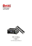
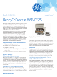
Illustration of the system
The illustration below shows a WAVE Bioreactor 20/50 instrument.
12
WAVE Bioreactor 20/50 and WAVEPOD II Operating Instructions 29-0057-07 AC
1 Introduction
1.3 WAVE Bioreactor system
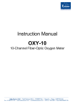
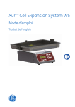
The illustration below shows the optional WAVEPOD II controller, which can be connected
to WAVE Bioreactor 20/50 and used to control culture parameters.
Tip:
The software UNICORN™ DAQ 1.0 for WAVE Bioreactor can be used for data
acquisition of the cultivation.
Main features
The main features of the WAVE Bioreactor system family are:
•
Gamma irradiated, single-use Cellbag bioreactors that protect against the risk of
cross-contamination, require no cleaning, and involve minimal validation.
•
Cellbag bioreactors are supplied ready-for-use, minimizing the time for preparation.
The Cellbag bioreactors are suitable for GMP commercial production without the
use of a biosafety cabinet.
•
No cell shear by sparged air bubbles.
•
Suitable for suspension, microcarrier, batch, fed-batch and perfusion culture applications.
•
Multiple configurations for control of parameters, such as pH and dissolved oxygen
(DO).
WAVE Bioreactor 20/50 and WAVEPOD II Operating Instructions 29-0057-07 AC
13
1 Introduction
1.3 WAVE Bioreactor system
•
Scalable systems capable of handling culture volumes from 0.1 L in WAVE Bioreactor
2/10 to 500 L in WAVE Bioreactor 500/1000.
•
Up to 1:10 expansion during one cultivation.
•
Built-in temperature control.
Terminology for pH and DO in
this manual
The terms...
refers to...
pH sensor and pHOPT sensor
the optical pH sensor used in Cellbag.
pH control and pHOPT control
pH control by WAVEPOD II.
DO sensor and DOOPT II sensor
the optical DO sensor used in Cellbag.
DO control and DOOPT II control
DO control by WAVEPOD II.
Note:
The suffix "II" in DOOPT II refers to the new patch-type DOOPT sensor integrated
into some Cellbag bioreactors, as opposed to the older external probe format
DOOPT sensor. For the WAVEPOD II instrument the term DOOPT is still used.
Applications
The WAVE Bioreactor family can be used for cell expansion, recombinant protein, virus
or vaccine production and high containment applications. Mammalian, insect, plant and
microbial cell cultivations can be performed; in either suspension or on microcarriers.
Options
A range of optional controllers, pumps, and sensors allow the culture conditions within
the Cellbag bioreactor to be monitored, maintained, and adjusted as necessary.
The optional WAVEPOD II controller integrates instrumentation associated with
WAVE Bioreactor 20/50. This includes pH, dissolved oxygen, and CO2/O2 gas mixing
controls.
14
WAVE Bioreactor 20/50 and WAVEPOD II Operating Instructions 29-0057-07 AC
1 Introduction
1.4 WAVE Bioreactor 20/50 user documentation
1.4
WAVE Bioreactor 20/50 user documentation
Introduction
This section describes the user documentation that is delivered with the WAVE Bioreactor
system.
User documentation
Document
Main contents
WAVE Bioreactor 20/50 and
WAVEPOD II Operating
Instructions
All instructions needed to run the WAVE Bioreactor
instrument, including, for example, installation, descriptions of the features, operation and maintenance.
UNICORN DAQ Help (if
UNICORN DAQ is included)
Dialog descriptions for UNICORN DAQ (from the
Help menu).
UNICORN DAQ 1.0 user documentation (if UNICORN DAQ is
included)
Overview and detailed descriptions of the features
in UNICORN DAQ. Instructions on how to use the
software. Workflow descriptions for common operations. Network setup and complete software installation. Administration of UNICORN DAQ and the
UNICORN DAQ database.
WAVE Bioreactor 20/50 and WAVEPOD II Operating Instructions 29-0057-07 AC
15
1 Introduction
1.5 Associated documentation
1.5
Associated documentation
Data Files and Application Notes
To order or download produced data files and application notes, see the instruction below.
Step
Action
1
Go to www.gelifesciences.com/wave.
2
Click Literature under Related information.
3
Select to download or order chosen literature.
Other
For further information about optional stand-alone instruments, refer to Stand-alone
instruments for WAVE Bioreactor 2/10 and 20/50 Operating Instructions or contact a GE
Healthcare representative.
16
WAVE Bioreactor 20/50 and WAVEPOD II Operating Instructions 29-0057-07 AC
2 Safety instructions
2
Safety instructions
About this chapter
This chapter describes safety compliance, safety labels, general safety precautions,
emergency procedures, power failure and recycling of WAVE™ instruments.
In this chapter
This chapter contains the following sections:
Section
See page
2.1 Safety precautions
18
2.2 Labels
26
2.3 Emergency procedures
28
2.4 Recycling procedures
30
2.5 Declaration of Hazardous Substances (DoHS)
31
WAVE Bioreactor 20/50 and WAVEPOD II Operating Instructions 29-0057-07 AC
17
2 Safety instructions
2.1 Safety precautions
2.1
Safety precautions
Introduction
Before installing, operating or maintaining the system, you must be aware of the hazards
described in this manual. Follow the instructions provided to avoid personal injury or
damage to the equipment. The safety precautions in the section are grouped into the
following categories:
•
General precautions
•
Personal protections
•
Installing and moving the instrument
•
System operation
•
Maintenance
General precautions
WARNING
Do not operate the WAVE systems in any other way than described
in the WAVE user documentation.
WARNING
Operation and user maintenance of the WAVE system should be
performed by properly trained personnel only
WARNING
Do not use any accessories not supplied or recommended by GE
Healthcare.
WARNING
Only Cellbag bioreactors approved by GE Healthcare for WAVE
may be used on the equipment.
18
WAVE Bioreactor 20/50 and WAVEPOD II Operating Instructions 29-0057-07 AC
2 Safety instructions
2.1 Safety precautions
Using Flammable Liquids
WARNING
WAVE Bioreactor is not designed to handle flammable fluids.
WAVE Bioreactor is not approved for work in a potentially explosive
atmosphere.
Using hazardous chemicals or
biological reagents
WARNING
When using hazardous chemicals or biological agents, take all
suitable protective measures, including appropriate precautions
to accommodate for the remote risk of Cellbag bioreactor leakage.
Personal protection
WARNING
Always use appropriate personal protective equipment during operation and maintenance of WAVE systems.
WARNING
Hazardous substances. When using hazardous chemical and biological agents, take all suitable protective measures, such as
wearing protective glasses and gloves resistant to the substances
used. Follow local and/or national regulations for safe operation
and maintenance of the system.
WAVE Bioreactor 20/50 and WAVEPOD II Operating Instructions 29-0057-07 AC
19
2 Safety instructions
2.1 Safety precautions
WARNING
Spread of biological agents. The operator has to take all necessary
actions to avoid spreading hazardous biological agents in the
vicinity of the instrument. The facility should comply with the national code of practice for biosafety.
Installing and moving the
instrument
WARNING
Emergency stop. Position the WAVE system so that the power
switch is easily accessible for power shut off. The power switch is
located at the rear of the instrument.
WARNING
Protective ground. The WAVE instruments must always be connected to a grounded power outlet.
WARNING
Heavy object. Filled Cellbag bioreactor have a considerable weight
and heavy lifts must be done with care. Use 1 person per multiple
of 15 kg weight, for example 3 persons for 30 to 45 kg. All lifting
and moving must be performed in accordance with local regulations.
WARNING
Disconnect power. Always disconnect power from the instrument
before connecting the WAVE Bioreactor instrument or WAVEPOD II
to any other instrument.
20
WAVE Bioreactor 20/50 and WAVEPOD II Operating Instructions 29-0057-07 AC
2 Safety instructions
2.1 Safety precautions
CAUTION
Disconnect all tubing, hoses and cables before moving the WAVE
instrument.
CAUTION
Ensure that all tubing, hoses and cables are placed so that the risk
for tripping accidents is minimized.
CAUTION
Make sure that there is enough free space around the instrument
for the rocking motion.
CAUTION
The safety switches of the WAVE instrument must be functionally
tested after the installation of the equipment or after the instrument
has been transported and every 6 months from then on. See
Chapter 9 Maintenance, on page 223 for proper method of testing.
CAUTION
To avoid overheating, do not operate the heater for more than a
few minutes without a filled Cellbag bioreactor on the Rocker tray.
System operation
WARNING
Biohazard. Make sure that the Cellbag bioreactor is sealed before
and during the culture process.
WAVE Bioreactor 20/50 and WAVEPOD II Operating Instructions 29-0057-07 AC
21
2 Safety instructions
2.1 Safety precautions
WARNING
Electrical shock hazard after spillage. If there is a risk that large
volumes of spilled liquid may penetrate the casing of the WAVE
instrument, immediately switch off the instrument, disconnect the
power cord, and contact an authorized service engineer.
WARNING
To prevent any gas leakage from the stand-alone instrument
CO2MIX20, always switch off the CO2 supply when not used. During
cultivation using CO2MIX20, make sure that the room is well ventilated.
WARNING
To prevent any gas leakage from the stand-alone instrument
O2MIX20, always switch off the O2 supply when not used. During
cultivation using O2MIX20, make sure that the room is well ventilated.
WARNING
If nitrogen is connected to the AIR IN there may be a leakage of
nitrogen inside WAVEPOD II during normal use, even if there is no
gas flow to the instrument. Make sure that the room is well ventilated and that the nitrogen is shut off when not needed.
WARNING
Do not inflate the Cellbag bioreactor with any other device than
the internal airpump. This has an automatic overpressure shutdown
that will prevent overpressure. Direct connection to a gas source
or use of any other pump may result in rupture of the Cellbag
bioreactor.
22
WAVE Bioreactor 20/50 and WAVEPOD II Operating Instructions 29-0057-07 AC
2 Safety instructions
2.1 Safety precautions
CAUTION
Pressure at the Air In port of WAVE Bioreactor must not exceed
0.1 bar. Exceeding this limit may cause rupture of the Cellbag
bioreactor. Provide suitable safety pressure relief equipment.
CAUTION
Pinch hazard. Remain clear of all moving parts during operation.
Stop the rocking motion before working on the Cellbag bioreactor
or Rocker tray.
CAUTION
Overheating is possible if the instrument is operated without a liquid-containing bag. Do not touch a potentially overheated Rocker
tray.
CAUTION
Leakage risk of biological substances. Before every use, check
all hoses for signs of cracking or tears. None of the air hoses should
contain liquids of any kind.
CAUTION
Remove any spillage on the floor immediately to minimize the risk
for slipping accidents.
CAUTION
Use only chemicals that have been proven not to be harmful to
the Cellbag bioreactor and the system.
CAUTION
When connecting gas to the equipment, ensure that the correct
gas, gas quality and gas pressure are used to avoid hazards or
undesired effects on the culture.
WAVE Bioreactor 20/50 and WAVEPOD II Operating Instructions 29-0057-07 AC
23
2 Safety instructions
2.1 Safety precautions
NOTICE
Ensure that the tubing is unobstructed and that gases can pass
freely through the tubing.
Maintenance
WARNING
Electrical shock hazard. All repairs should be done by service
personnel authorized by GE Healthcare. Do not open any covers
or replace parts unless specifically stated in the user documentation.
WARNING
Disconnect power. Always disconnect power from the instrument
before performing any work or maintenance task on the instrument.
WARNING
Always clean the equipment in a well ventilated area. Never douse
or immerse any part of the instrument with any liquid. When
cleaning is required, use only water and alcohol. Always ensure
that the instrument is completely dry before plugging it in. Make
sure to follow all environmental, health, and safety guidelines pertaining to the materials used.
WARNING
Only spare parts that are approved or supplied by GE Healthcare
may be used for maintaining or servicing the system.
CAUTION
Water should not be applied directly to the instrument.
24
WAVE Bioreactor 20/50 and WAVEPOD II Operating Instructions 29-0057-07 AC
2 Safety instructions
2.1 Safety precautions
CAUTION
Do not connect power to the instrument until it is completely dry.
WAVE Bioreactor 20/50 and WAVEPOD II Operating Instructions 29-0057-07 AC
25
2 Safety instructions
2.2 Labels
2.2
Labels
This section describes safety labels and labels concerning hazardous substances that
are attached to the WAVE instruments.
Labels on the instrument
The illustration below shows an example of the identification label that is attached to
the WAVE instruments.
WAVE Bioreactor
28941342
BASE20/50EHT 220-240V
~
Code no: 28942137 Voltage:220-240 V
Serial no: 1234567 Frequency: 50/60 Hz
Mfg Year: 2009
Max Power: 630 VA
Fuse:
2x T 6.3AL 250 V
N3732
Made in Sweden
GE Healthcare Bio-Sciences AB
751 84 Uppsala Sweden
WAVEPOD II
Symbols used in safety labels
Label
Description
Warning! Read the user documentation before using the system. Do
not open any covers or replace parts unless specifically stated in the
user documentation.
26
WAVE Bioreactor 20/50 and WAVEPOD II Operating Instructions 29-0057-07 AC
2 Safety instructions
2.2 Labels
Label
Description
The system complies with applicable European directives.
The system complies with the requirements for electromagnetic
compliance (EMC) in Australia and New Zealand.
This symbol indicates that WAVEPOD II has been certified by a Nationally Recognized Testing Laboratory (NTRL). NRTL means an organization,
which is recognized by the US Occupational Safety and Health Administration (OSHA) as meeting the legal requirements of Title 29 of the
Code of Federal Regulations (29 CFR), Part 1910.7.
Indicates that there is a risk for body parts getting caught between
two parts of the instrument and that care must be taken to avoid injury.
Labels concerning hazardous
substances
Label
Properties
This symbol indicates that the waste of electrical and electronic
equipment must not be disposed as unsorted municipal waste and
must be collected separately. Please contact an authorized representative of the manufacturer for information concerning the decommissioning of equipment.
This symbol indicates that the product contains hazardous materials
in excess of the limits established by the Chinese standard SJ/T113632006 Requirements for Concentration Limits for Certain Hazardous
Substances in Electronics.
WAVE Bioreactor 20/50 and WAVEPOD II Operating Instructions 29-0057-07 AC
27
2 Safety instructions
2.3 Emergency procedures
2.3
Emergency procedures
Introduction
This section describes how to do an emergency shutdown of a WAVE instrument. The
section also describes the result in the event of power failure.
Safety switches
White rubber safety switches are located below the Rocker tray. If either of the safety
switches is hit, the rocking motion stops and the Rocker tray moves to a level position.
If a safety switch has been hit, power must be turned off (O) and on (I) to reset the safety
switch.
Emergency procedures
In an emergency situation, do as follows to stop the run:
28
Step
Action
1
Switch off the power to the instrument by pressing the power switch to the
O position.
2
If required, disconnect the power cord from the power outlet.
WAVE Bioreactor 20/50 and WAVEPOD II Operating Instructions 29-0057-07 AC
2 Safety instructions
2.3 Emergency procedures
Reset the Safety switch
To reset the safety switch:
•
Turn off the power to the instrument by pressing the power switch to the O position.
•
Turn on the power to the instrument by pressing the power switch to the I position.
Power failure
In the event of power failure, the run is immediately interrupted. If the AUTOSTART option
is set to ON, the operation is automatically resumed on power up. For troubleshooting,
see Section 10.1 General problems, on page 236.
WAVE Bioreactor 20/50 and WAVEPOD II Operating Instructions 29-0057-07 AC
29
2 Safety instructions
2.4 Recycling procedures
2.4
Recycling procedures
The equipment shall be decontaminated before decommissioning and all local regulations
shall be followed with regard to scrapping of the equipment.
Disposal, general instructions
When taking WAVE Bioreactor systems out of service, the different materials must be
separated and recycled according to national and local environmental regulations.
Recycling of hazardous
substances
WAVE Bioreactor systems contain hazardous substances. Detailed information is available
from your local GE Healthcare representative.
Disposal of electrical
components
Waste of electrical and electronic equipment must not be disposed as unsorted municipal
waste and must be collected separately. Please contact an authorized GE Healthcare
representative for information concerning the decommissioning of your equipment.
30
WAVE Bioreactor 20/50 and WAVEPOD II Operating Instructions 29-0057-07 AC
2 Safety instructions
2.5 Declaration of Hazardous Substances (DoHS)
2.5
Declaration of Hazardous Substances (DoHS)
Introduction
The following product pollution control information is provided according to SJ/T113642006 Marking for Control of Pollution caused by Electronic Information Products.
根据SJ/T11364-2006《电子信息产品污染控制标识要求》特提供如下有关污染 控制
方面的信息
Symbols used in pollution control
label
电子信息产品污染控制标志说明
Label
Meaning
This symbol indicates the product contains hazardous materials in excess of the limits established by the Chinese standard SJ/T11363-2006
Requirements for Concentration Limits for Certain Hazardous Substances in Electronic Information Products. The number in the symbol
is the Environment-friendly Use Period (EFUP), which indicates the period
during which the toxic or hazardous substances or elements contained
in electronic information products will not leak or mutate under normal
operating conditions so that the use of such electronic information
products will not result in any severe environmental pollution, any
bodily injury or damage to any assets. The unit of the period is “Year”.
In order to maintain the declared EFUP, the product shall be operated
normally according to the instructions and environmental conditions
as defined in the product manual, and periodic maintenance schedules
specified in Product Maintenance Procedures shall be followed strictly.
Consumables or certain parts may have their own label with an EFUP
value less than the product. Periodic replacement of those consumables
or parts to maintain the declared EFUP shall be done in accordance
with the Product Maintenance Procedures.
This product must not be disposed of as unsorted municipal waste,
and must be collected separately and handled properly after decommissioning.
WAVE Bioreactor 20/50 and WAVEPOD II Operating Instructions 29-0057-07 AC
31
2 Safety instructions
2.5 Declaration of Hazardous Substances (DoHS)
Label
Meaning
该标志表明本产品含有超过SJ/T11363-2006《电子信息产品中有毒
有害物质的限 量要求》中限量的有毒有害物质。标志中的数字为本
产品的环保使用期,表明本 产品在正常使用的条件下,有毒有害物
质不会发生外泄或突变,用户使用本产品 不会对环境造成严重污染
或对其人身、财产造成严重损害的期限。单位为年。
为保证所申明的环保使用期限,应按产品手册中所规定的环境条件
和方法进行正 常使用,并严格遵守产品维修手册中规定的期维修和
保养要求。
产品中的消耗件和某些零部件可能有其单独的环保使用期限标志,
并且其环保使 用期限有可能比整个产品本身的环保使用期限短。应
到期按产品维修程序更换那 些消耗件和零部件,以保证所申明的整
个产品的环保使用期限。
本产品在使用寿命结束时不可作为普通生活垃圾处理,应被单独收
集妥善处理
List of hazardous substances and
their concentrations
产品中有毒有害物质或元素的名称及含量
Indication for each major part if substance exceeds limit
Value
Meaning
O
Indicates that this toxic or hazardous substance contained in all of the
homogeneous materials for this part is below the limit requirement in
SJ/T11363-2006.
表示该有毒有害物质在该部件所有均质材料中的含量均在SJ/T113632006 标准规定的限量要 求以下
X
Indicates that this toxic or hazardous substance contained in at least
one of the homogeneous materials used for this part is above the limit
requirement in SJ/T11363-2006.
•
Data listed in the table represents best information available at the
time of publication
表示该有毒有害物质至少在该部件的某一均质材料中的含量超出
SJ/T11363-2006 标准规定的
限量要求
•
32
此表所列数据为发布时所能获得的最佳信息
WAVE Bioreactor 20/50 and WAVEPOD II Operating Instructions 29-0057-07 AC
2 Safety instructions
2.5 Declaration of Hazardous Substances (DoHS)
List of hazardous substances
Component
name
Hazardous substance
有毒有害物质或元素
部件名称
Pb
Hg
Cd
Cr6+
PBB
PBDE
铅
汞
镉
六价铬
多溴联苯
多溴二苯醚
28-9847-40 1
X
X
O
O
O
O
28-9847-41 1
X
X
O
O
O
O
28-9847-42 1
X
X
O
O
O
O
28-9413-41 1
X
O
O
O
O
O
28-9413-42 1
X
O
O
O
O
O
28-9413-43 1
X
O
O
O
O
O
28-9413-44 1
X
O
O
O
O
O
28-9413-45 1
X
O
O
O
O
O
28-9413-46 1
X
O
O
O
O
O
28-9413-47 1
X
O
O
O
O
O
28-9413-48 1
X
O
O
O
O
O
28-9413-49 1
X
O
O
O
O
O
28-9413-50 1
X
O
O
O
O
O
28-9413-51 1
X
O
O
O
O
O
28-9413-52 1
X
O
O
O
O
O
28-9413-53 1
X
O
O
O
O
O
28-9413-54 1
X
O
O
O
O
O
28-9413-55 1
X
O
O
O
O
O
28-9413-56 1
X
O
O
O
O
O
28-4115-26 1
X
O
O
O
O
X
28-9416-44 1
X
O
O
O
O
X
WAVE Bioreactor 20/50 and WAVEPOD II Operating Instructions 29-0057-07 AC
33
2 Safety instructions
2.5 Declaration of Hazardous Substances (DoHS)
Component
name
Hazardous substance
有毒有害物质或元素
部件名称
1
34
Pb
Hg
Cd
Cr6+
PBB
PBDE
铅
汞
镉
六价铬
多溴联苯
多溴二苯醚
28-4115-27 1
X
O
O
O
O
X
28-9416-45 1
X
O
O
O
O
X
28-4115-28 1
X
O
O
O
O
X
28-9416-46 1
X
O
O
O
O
X
28-4115-30 1
X
O
O
O
O
X
28-9416-47 1
X
O
O
O
O
X
28-4115-34 1
O
O
O
O
O
O
28-4115-35 1
O
O
O
O
O
O
28-4115-37 1
O
O
O
O
O
O
28-4115-38 1
O
O
O
O
O
O
The product has not been tested as per the Chinese standard SJ/T11363-2006 Requirements
for Concentration Limits for Certain Hazardous Substances in Electronic Information Product.
WAVE Bioreactor 20/50 and WAVEPOD II Operating Instructions 29-0057-07 AC
3 System description
3
System description
About this chapter
This chapter describes the features of WAVE Bioreactor 20/50.
In this chapter
This chapter contains the following sections:
Section
See page
3.1 Overview description
36
3.2 Functional description
39
3.3 Cellbag bioreactor
42
3.4 WAVEPOD II
47
3.5 WAVE Bioreactor system configuration
51
WAVE Bioreactor 20/50 and WAVEPOD II Operating Instructions 29-0057-07 AC
35
3 System description
3.1 Overview description
3.1
Overview description
System overview
A complete WAVE Bioreactor 20/50 system consists of:
•
WAVE Bioreactor 20/50
•
Rocker tray (ordered separately)
•
Gamma irradiated disposable Cellbag bioreactor (ordered separately)
•
WAVEPOD II (optional)
•
Lid (optional)
•
Stand-alone instruments (optional)
•
pH and DO sensors (integrated into Cellbag bioreactors, optional)
•
UNICORN DAQ software (optional)
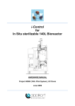
Front view of
WAVE Bioreactor 20/50
The illustration below shows the front of the WAVE Bioreactor 20/50 instrument with an
installed Rocker tray.
36
Part
Function
1
Protective bellows, rocking mechanism
2
Rocking platform
3
Rocker tray
4
Detachable touch screen
WAVE Bioreactor 20/50 and WAVEPOD II Operating Instructions 29-0057-07 AC
3 System description
3.1 Overview description
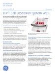
Illustration of Cellbag
The cell culture bag is provided in many different configurations; standard assortments
and customized.
This illustration shows an example of a Cellbag configuration.
3
2
4
1
7
6
Part
Function
1
Cellbag rod
2
Outlet air filter
3
Inlet air filter
4
Spare Luer port
5
CLAVE™ needleless sampling port
6
Port for additions
7
Port for additions and harvest
WAVE Bioreactor 20/50 and WAVEPOD II Operating Instructions 29-0057-07 AC
5
37
3 System description
3.1 Overview description
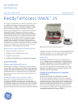
Front view of WAVEPOD II
The optional WAVEPOD II controller monitors and controls culture parameters. The illustration below shows the front of the WAVEPOD II controller.
1
2
Part
Function
1
Touch screen
2
Connectors to sensor cables and gas tubing
Optional features
For information about other optional instruments, see Section 3.5 WAVE Bioreactor system
configuration, on page 51.
For information about UNICORN DAQ, read the UNICORN DAQ 1.0 user documentation.
38
WAVE Bioreactor 20/50 and WAVEPOD II Operating Instructions 29-0057-07 AC
3 System description
3.2 Functional description
3.2
Functional description
Operating principle
The Cellbag bioreactor is placed on WAVE Bioreactor 20/50, is inflated with gas, partially
filled with culture medium and is then inoculated with cells.
A wave motion is induced in the cultivation contained in the Cellbag bioreactor by the
rocking mechanism. The wave motion mixes the fluid in the Cellbag bioreactor and
suspends any cells and particles. The wave-induced agitation does not require an invasive
mechanical mixer or gas sparging.
The wave motion also generates free surface for enabling effective oxygen transfer from
the headspace of the bioreactor. Air is continuously passed through the bioreactor
headspace in order to supply oxygen and remove metabolic waste gases.
Aeration is provided by an internal air pump and mass-flow controller. Alternatively, an
optional gas mixer can be used.
Optionally, a WAVEPOD II controller is used to control pH, dissolved oxygen, airflow, and
CO2 and O2 gas mixing.
Illustration of wave motion
1
2
4
3
Stage
Description
1
Air enters the Cellbag bioreactor through the inlet filter. It inflates the bag
and provides oxygen to the culture.
2
Air and metabolic gases leave the Cellbag bioreactor through the outlet filter
and pressure control valve. The pressure control valve ensures that a correct
and constant overpressure is maintained inside the Cellbag bioreactor.
3
The rocking mechanism sets the rocking platform in motion.
4
Waves are formed during the rocking. The culture is cautiously mixed, and
oxygen is transferred into the culture.
WAVE Bioreactor 20/50 and WAVEPOD II Operating Instructions 29-0057-07 AC
39
3 System description
3.2 Functional description
Control parameters
Available control parameters
Control of rocking, temperature and aeration are all available by default. Other control
parameters depend on the system configuration.
Rocking control
The degree of mixing and oxygen transfer can be controlled by adjusting the rocking
speed and angle.
Temperature control
Temperature is controlled by a heating plate that is placed between the rocking platform
and the Rocker tray. A non-invasive temperature sensor is attached to the left side of
the tray. The sensor cable plugs into a jack located on the side of the instrument. The
cell culture bag is later placed on the Rocker tray.
Note:
During dual operation, see Section 3.5 WAVE Bioreactor system configuration,
on page 51, temperature sensors are used on both the left and right side, one
for each bag.
Aeration
Air is drawn in by internal pumps inside WAVE Bioreactor and pumped into the headspace
of the Cellbag bioreactor.
Alternatively, WAVEPOD II can provide aeration control.
CO2 and O2 gas concentration control
Air is drawn in by the internal pump from the inlet air port. O2 or CO2, if connected to
their designated side panel ports, enables mixing of air with CO2 and/or O2 gas to a set
concentration. This operation requires a CO2 or O2 configured WAVE Bioreactor 20/50
instrument.
Alternatively, the inlet air can be mixed with CO2 and/or O2 gas to a set concentration
inside WAVEPOD II. The controlled gas mix is then connected directly to the Cellbag
bioreactor, not via the WAVE Bioreactor instrument.
DO control
Dissolved oxygen (DO) can be measured with a WAVEPOD II in combination with an optical DO sensor integrated into the bottom of DOOPT II Cellbag configurations. The DO
can be manually or automatically controlled via WAVEPOD II by changing the O2 concentration for the air pumped into the Cellbag bioreactor or by changing the rocking speed.
In addition, the rocking angle can be set manually.
40
WAVE Bioreactor 20/50 and WAVEPOD II Operating Instructions 29-0057-07 AC
3 System description
3.2 Functional description
pH control
pH can be measured using a WAVEPOD II in combination with an optical pH sensor integrated into the bottom of pHOPT Cellbag configurations. pH control is achieved by adding
acid or base solution, or by adding base and controlling the CO2 concentration for the
air added to the Cellbag bioreactor. For addition of acid and/or base one additional
pump is required per solution.
Perfusion control
Perfusion can be performed and controlled using a WAVE Bioreactor 20/50 version with
integral load cell. Feed and harvest PUMP20 pumps are also required. Periodically during
perfusion, fresh culture medium is added and cell-free culture media removed.
Instrument user interface
WAVE Bioreactor
WAVE Bioreactor is controlled by a touch screen located on the front of the instrument.
The touch screen shows the current state of the system and can also be used to control
the system. The touch screen can be detached from the instrument for more convenient
operation. A cable connects the screen to the instrument. For detailed descriptions of
the control functions, see Chapter 5 WAVE Bioreactor control system, on page 83.
WAVEPOD II
The optional WAVEPOD II controller displays system information on an integrated touch
screen. For detailed descriptions of the control functions, see Chapter 6 WAVEPOD II
Control system, on page 115.
WAVE Bioreactor 20/50 and WAVEPOD II Operating Instructions 29-0057-07 AC
41
3 System description
3.3 Cellbag bioreactor
3.3
Cellbag bioreactor
Introduction
Cell cultivation is performed inside the Cellbag bioreactor. The Cellbag bioreactor is delivered gamma irradiated and ready for use. It is intended for single use and must be
discarded after use.
Please take a few moments to familiarize yourself with the features of the Cellbag
bioreactor.
Illustration
Schematic illustration of a Cellbag bioreactor.
Description
Each Cellbag bioreactor is packed in two protective plastic bags. For Cellbag bioreactors
that have optical pH and/or DO sensors, the inner bag is made of a black plastic that
prevents the optical sensors from being exposed to light before use. The outer bag and
its entire content have been gamma irradiated.
The Cellbag bioreactor itself consists of a multi layer film designed to provide strength,
flexibility, excellent gas barrier performance and inert product contact. The fluid contact
layer is made of ethylene vinyl acetate (EVA) and the outer layer consists of linear low
density polyethylene (LLDPE). Proprietary composites provide strength and low gas permeability. All contact components meet USP Class VI specifications and all Cellbag
bioreactors are lot tested for endotoxin.
Maximum operating pressure is 0.1 bar (1.5 psig), recommended operating pressure is
5 to 7.5 mbar (2 to 3 inches water).
42
WAVE Bioreactor 20/50 and WAVEPOD II Operating Instructions 29-0057-07 AC
3 System description
3.3 Cellbag bioreactor
NOTICE
The black inner protective bag is removed immediately before use.
It should not be opened before you enter the production room.
Cellbag sizes
The following Cellbag bioreactor sizes are available for WAVE Bioreactor 20/50:
•
2L
•
10 L
•
20 L
•
22 L
•
50 L
Selection guide
For cell culture volumes
Use Cellbag size
0.1 - 1 L
2L
0.5 - 5 L
10 L
1 - 10 L
20 L or 22 L
5 - 25 L
50 L
WAVE Bioreactor 20/50 and WAVEPOD II Operating Instructions 29-0057-07 AC
43
3 System description
3.3 Cellbag bioreactor
Cellbag components
The cell culture bag is provided in many different configurations, standard assortments
and customized. This illustration shows an example of a Cellbag bioreactor that has the
following gamma irradiated components:
4
3
2
1
5
6
7
Part
Component
Description
1
Cellbag rod
Fixes the bag to the Rocker tray.
2
•
Outlet air filter
•
Pressure control valve
•
The hydrophobic outlet filter removes
particles from the air vented from the
bioreactor. This filter is rated to remove
airborne particulates of 0.2 micron or
larger, allowing for containment of the
bioreactor contents.
The composition of the filter membrane
enables wet gases and condensate to
pass without compromising filter functionality.
•
44
The pressure control valve is attached
to the outlet air filter. The purpose of
the pressure control valve is to maintain
constant pressure in the bioreactor regardless of inlet airflow rate.
WAVE Bioreactor 20/50 and WAVEPOD II Operating Instructions 29-0057-07 AC
3 System description
3.3 Cellbag bioreactor
Part
Component
Description
3
Inlet air filter
The hydrophobic inlet filter removes particles from the air before the air is introduced
into the Cellbag bioreactor. The filters used
are rated to remove air-borne particulates
of 0.2 micron or larger.
4
Luer ports
Additional luer ports may be present on the
Cellbag bioreactor for additions.
5
CLAVE sampling
port
This port is equipped with a self-sealing luer
fitting for easy aseptic sampling using a
needleless conventional syringe with luer
connection.
6
Addition port
This port is equipped with a luer quick connector. Connection and disconnection
should be done using proper aseptical procedures. Alternatively, a tube fuser may be
used.
7
Addition/harvest
port
This port is equipped with an MPC quick
connector. Connection and disconnection
should be done using proper aseptical procedures. Alternatively, a tube fuser may be
used.
Not shown
ReadyMate™
connection
Cellbag bioreactors may be equipped with
ReadyMate aseptic connectors for high
fluid throughput connection.
Not shown
pHOPT port
pHOPT configured bags have a port with
an optical pH sensor on the bottom of the
bag.
Not shown
DOOPT II port
DOOPT II configured bags have a port with
an optical DO sensor on the bottom of the
bag.
Not shown
Tubing Connection
A length of tubing is provided for easy sterile connections using standard tube fusing
devices. This tubing is terminated with a
standard luer connector so that connections also can be made inside a laminar
flow hood.
WAVE Bioreactor 20/50 and WAVEPOD II Operating Instructions 29-0057-07 AC
45
3 System description
3.3 Cellbag bioreactor
Part
Component
Description
Not shown
Options
Custom cell culture bags with variation of
ports and their port components (tubing,
connectors, etc.) can be manufactured for
specific applications within the Cellbag design space.
Note:
Cellbag bioreactors with internal cell retention filters for perfusion culture are
available in several sizes.
Convenient after run procedures
The system has minimal turnaround time. The Cellbag bioreactor is in itself a convenient
harvest container. The completed batch can be removed and a new Cellbag bioreactor
be placed on the instrument.
In the event of product changeover or contamination, conventional bioreactors require
time-consuming validated cleaning and decontamination. This can take several weeks
during which the bioreactor cannot be used. In contrast, the WAVE Bioreactor system
has minimal downtime. It also offers assurance against cross-contamination or product
carryover.
46
WAVE Bioreactor 20/50 and WAVEPOD II Operating Instructions 29-0057-07 AC
3 System description
3.4 WAVEPOD II
3.4
WAVEPOD II
Introduction
The WAVEPOD II controller integrates supporting instrumentation associated with
WAVE Bioreactor 20/50. Depending on the configuration, the controls include all or some
of the following: pH, dissolved oxygen, airflow, and CO2 and O2 gas mixing.
Many parameters of WAVE Bioreactor can be remote controlled from the WAVEPOD II
Touch screen.
Dual WAVE Bioreactor 20/50 instruments can handle two Cellbag bioreactors, as described in Rocker tray and Cellbag bioreactor, on page 53. One WAVEPOD II is required
for each Cellbag.
Illustrations of WAVEPOD II
The illustration below shows the location of the main parts of the front of WAVEPOD II.
1
2
3
4
5
Part
Function
1
Touch screen
6
WAVE Bioreactor 20/50 and WAVEPOD II Operating Instructions 29-0057-07 AC
7
47
3 System description
3.4 WAVEPOD II
Part
Function
2
PHOPT connector
3
CO2 IN connector
4
O2 IN connector
5
AIR IN connector
6
MIX OUT connector
7
DOOPT II connector
The illustration below shows the location of the main parts of the back of WAVEPOD II.
8
9
10
11
12
48
Part
Function
8
Lifting handle
9
Ventilation
10
Connectors to instruments, pumps, computers
11
Power connector
12
Power switch
WAVE Bioreactor 20/50 and WAVEPOD II Operating Instructions 29-0057-07 AC
3 System description
3.4 WAVEPOD II
Available modules for
WAVEPOD II
WAVEPOD II can be configured to have the following modules integrated. The modules
are preinstalled at purchase.
Module
Description
pH controller
Enables on-line measurement of pH in the Cellbag bioreactor using an optical sensor and feed-back control with
acid/base additions. The controller can operate WAVE
PUMP20 units or user-supplied pumps. It can also control
pH through changes in the CO2 composition of the inlet
gas, if a CO2 controller is installed into WAVEPOD II.
DO (Dissolved Oxygen)
controller
Enables on-line measurement of dissolved oxygen in the
Cellbag bioreactor using an optical sensor and control via
changes in rocking speed. It can also control DO through
changes in the O2 composition of the inlet gas, if a O2
controller is installed into WAVEPOD II.
Airflow controller
Controls the flow of air through the Cellbag bioreactor
using a thermal mass flow sensor and a flow control valve.
CO2 controller
Measures and controls the CO2 concentration in the inlet
gas to the Cellbag bioreactor using an internal non-dispersive infrared (NDIR) sensor and an internal controller.
O2 controller
Measures and controls the O2 concentration in the inlet
gas to the Cellbag bioreactor using an internal zirconium
oxide sensor and an internal controller.
Note:
The CO2 or O2 gas source should be pure, since impurities may affect the culture.
Main features
•
Compact design provides all major parameter controls
•
Large color touchscreen provides easy user access
•
Integrates with WAVE Bioreactor 20/50 to provide a unified control unit with control
capabilities
•
Output for data acquisition, to, for example, UNICORN DAQ via an Ethernet converter
•
Date-stamped alarms stored in non-volatile memory for easy troubleshooting
WAVE Bioreactor 20/50 and WAVEPOD II Operating Instructions 29-0057-07 AC
49
3 System description
3.4 WAVEPOD II
50
•
Integrated control for optional, external acid/base pumps
•
Alarm contacts for chart recorders and remote monitoring systems
WAVE Bioreactor 20/50 and WAVEPOD II Operating Instructions 29-0057-07 AC
3 System description
3.5 WAVE Bioreactor system configuration
3.5
WAVE Bioreactor system configuration
Introduction
The WAVE Bioreactor systems provide scalable cell cultivation possibilities with control
of key parameters. Several different configurations are available for enabling optimal
user flexibility and control of some or all of these key parameters.
The control of the parameters can be performed by the following:
•
Integrated modules in the WAVE Bioreactor instrument
•
Integrated modules in the WAVEPOD II controller
•
Separate stand-alone instruments
pH control alternatives and
hardware requirements
The pH of the growth medium can be controlled in various ways, depending on the
hardware installed with the WAVE Bioreactor instrument. pH can be controlled by the
addition of acid or base via pumps, by controlling the CO2 concentration, or a combination
of the two. The following table outlines the hardware requirements for the various pH
control methods.
Strategy for pH control
Instrument requirements
Indirect control by controlling the CO2 concentration
•
WAVE Bioreactor with an integrated CO2 control
module, or
•
WAVEPOD II with CO2 control module, or
•
CO2MIX20 (stand-alone instrument), or
•
CO2MIX20-R (stand-alone instrument)
•
WAVEPOD II with pHOPT control module and PUMP20
and a pHOPT configured Cellbag bioreactor
Feed-back control with
base addition to increase pH and acid addition to decrease pH
Note:
Two PUMP20 pumps will be needed if both acid and base
addition is required.
WAVE Bioreactor 20/50 and WAVEPOD II Operating Instructions 29-0057-07 AC
51
3 System description
3.5 WAVE Bioreactor system configuration
Strategy for pH control
Instrument requirements
Feed-back control with
base additions to increase pH and control
of the CO2 concentration to decrease pH.
•
WAVEPOD II with pHOPT and CO2 control modules,
PUMP20 and a pHOPT configured Cellbag bioreactor.
In this manual, focus is on using WAVEPOD II for parameter controls. For further information about optional stand-alone modules, please refer to Stand-alone instruments for
WAVE Bioreactor 2/10 and 20/50 Operating Instructions or www.gelifesciences.com/wave.
Optional controls
Several parameters can be controlled using optional instrumentation or configuration,
see table below. For more information about the stand-alone instruments, see Stand-alone
instruments for WAVE Bioreactor 2/10 and 20/50 Operating Instructions or
www.gelifesciences.com/wave, or contact GE Healthcare.
Function
Product name
Location
Dissolved oxygen controller
DOOPT II
WAVEPOD II
CO2/air controller
CO2MIX20
WAVEPOD II or
WAVE Bioreactor instrument
or
stand-alone instrument
CO2/air controller (rotameter model)
CO2MIX20-R
stand-alone instrument
O2/air controller
O2MIX20
WAVEPOD II or
WAVE Bioreactor instrument
or
stand-alone instrument
O2/air controller (rotameter model)
O2MIX20-R
stand-alone instrument
Peristaltic feed/harvest or acid/base pump
PUMP20
stand-alone instrument
pH controller (when combined with PUMP20)
pHOPT
WAVEPOD II
Weight controller (can be used for perfusion)
LOADCELL20
WAVE Bioreactor instrument
Note:
52
LOADCELL20 is pre-installed if the load cell option was ordered with
WAVE Bioreactor 20/50. LOADCELL20 cannot be ordered separately
WAVE Bioreactor 20/50 and WAVEPOD II Operating Instructions 29-0057-07 AC
3 System description
3.5 WAVE Bioreactor system configuration
Note:
UNICORN DAQ 1.0 is compatible with WAVEPOD II and LOADCELL20.
Rocker tray and Cellbag
bioreactor
Several Cellbag bioreactor sizes are compatible with the WAVE Bioreactor 20/50 instruments, specific sizes depend on the rocker KIT used. This enables scale-up using the
same instrument.
Configured versions of the WAVE Bioreactor 20/50 instrument enables dual operation,
which is the use of two Cellbag bioreactors on one Rocker tray. In dual version, both the
left and the right hand side panels have connectors for air and temperature sensors.
For WAVE Bioreactor 20/50 the following Rocker tray kits and bags can be used:
WAVE Bioreactor
Rocker tray kit
Cellbag bioreactor
size
WAVE Bioreactor 20/50- single operation
KIT20EHT
•
2L
•
10 L
•
20 L
•
22 L
•
50 L
•
2x2L
•
2 x 10 L
WAVE Bioreactor 20/50- single operation
WAVE Bioreactor 20/50- dual operation
KIT50EHT
KIT20EHTD
WAVE Bioreactor 20/50- dual operation
KIT50EHTD
•
2 x 22 L
WAVE Bioreactor 20/50- single operation on dual Rocker tray kit
KIT20EHTD
•
20 L
WAVE Bioreactor 20/50- single operation on dual Rocker tray kit
KIT50EHTD
•
50 L
Tip:
It is possible to place only one bag on the left side of a dual Rocker tray kit.
WAVE Bioreactor 20/50 and WAVEPOD II Operating Instructions 29-0057-07 AC
53
4 Installation
4
Installation
About this chapter
This chapter provides information regarding installation of WAVE Bioreactor 20/50,
WAVEPOD II and UNICORN DAQ 1.0.
For further information on installation, refer to the user documentation listed in Section 1.4
WAVE Bioreactor 20/50 user documentation, on page 15.
In this chapter
This chapter contains the following sections:
Section
54
See page
4.1 Site requirements
55
4.2 Installation of WAVE Bioreactor 20/50
58
4.3 Transportation
71
4.4 Installation of WAVEPOD II
72
4.5 Connecting to UNICORN DAQ 1.0
80
WAVE Bioreactor 20/50 and WAVEPOD II Operating Instructions 29-0057-07 AC
4 Installation
4.1 Site requirements
4.1
Site requirements
Precautions
WARNING
If nitrogen is connected to the AIR IN there may be a leakage of
nitrogen inside WAVEPOD II during normal use, even if there is no
gas flow to the instrument. Make sure that the room is well ventilated and that the nitrogen is shut off when not needed.
WARNING
To prevent any gas leakage from the stand-alone instrument
CO2MIX20, always switch off the CO2 supply when not used. During
cultivation using CO2MIX20, make sure that the room is well ventilated.
WARNING
To prevent any gas leakage from the stand-alone instrument
O2MIX20, always switch off the O2 supply when not used. During
cultivation using O2MIX20, make sure that the room is well ventilated.
CAUTION
When connecting gas to the equipment, ensure that the correct
gas, gas quality and gas pressure are used to avoid hazards or
undesired effects on the culture.
Power requirement
Parameter
Requirement
Electrical power
110 to 120 V ~ or 220 to 240 V ~, 50/60 Hz
WAVE Bioreactor 20/50 and WAVEPOD II Operating Instructions 29-0057-07 AC
55
4 Installation
4.1 Site requirements
Site environment
Parameter
Requirement
Ambient temperature, WAVE Bioreactor 20/50
4°C to 40°C
Ambient temperature, WAVEPOD II
4°C to 40°C
Humidity, WAVE Bioreactor 20/50
< 95%, non-condensing
Humidity, WAVEPOD II
10% to 90%, non-condensing
Note:
The ambient temperature must be at least 5°C lower than the desired culture
growth temperature for satisfactory temperature control.
Requirements on placement
•
The bench must be stable and withstand vibration from the rocking.
•
The bench must be able to bear the total weight of the instrument, WAVEPOD II (if
used), and the filled Cellbag bioreactor. See Section A.1 Specifications, on page 252
for instrument specifications. If other optional instruments are installed, their weights
must also be included, see separate specifications.
•
At least 25 cm workspace must be available on either side of WAVE Bioreactor for
safety and ease of access, and at least 10 cm in front and behind for adequate
ventilation.
•
Do not place soft material under WAVE Bioreactor or WAVEPOD II. It may block the
ventilation inlet.
NOTICE
When using Cellbag bioreactors with built-in optical sensors, such
as pHOPT or DOOPT II sensors, WAVE Bioreactor should be placed
away from intense light such as direct sunlight. Intense light will
deteriorate the optical sensors.
Optional utilities
56
Parameter
Requirement
CO2, 100%
1.5 slpm at 0.7 to 1.0 bar (10 to 15 psig). Minimum delivery 0.2 lpm.
WAVE Bioreactor 20/50 and WAVEPOD II Operating Instructions 29-0057-07 AC
4 Installation
4.1 Site requirements
Parameter
Requirement
O2
5.0 slpm at 0.7 to 1.0 bar (10 to 15 psig). Minimum delivery 0.2 lpm.
AIR IN supply
0.1 to 0.2 bar (1 to 3 psig)
Tip:
Ambient or process air can be used. However, ensure that the maximum
pressure listed above is not exceeded.
Tip:
It is possible to produce an oxygen mixture with concentrations below 21%
(air), by connecting a nitrogen stream to the AIR IN port (< 0.2 bar or 3 psig)
on WAVEPOD II.
WAVE Bioreactor 20/50 and WAVEPOD II Operating Instructions 29-0057-07 AC
57
4 Installation
4.2 Installation of WAVE Bioreactor 20/50
4.2
Installation of WAVE Bioreactor 20/50
Unpacking
Unpack the equipment and place it on a stable surface.
Check the equipment for any apparent damage before starting installation. Document
any damage carefully and contact your GE Healthcare representative.
WAVE Bioreactor 20/50
rear panel
The illustration below shows the rear panel of WAVE Bioreactor 20/50.
10
1
58
2
3
4
Part
Function
1
DATAPORT1 and 2
2
FEED PUMP port
3
HARVEST PUMP port
4
ALARM ANALOG OUT port
5
LOAD CELL port
6
FILTER HEATER ports
7
HEATER port
8
Power port
9
Power switch
10
Fuse holder
5
6
7
8 9
WAVE Bioreactor 20/50 and WAVEPOD II Operating Instructions 29-0057-07 AC
4 Installation
4.2 Installation of WAVE Bioreactor 20/50
WAVE Bioreactor 20/50
side panel
The illustration below shows the side panel of WAVE Bioreactor 20/50.
Note:
In dual versions of the instrument, several ports are provided on a side panel
on the right hand side.
Part
Function
1
Temp port
2
Air Out port
3
Air In port
Installation of the Rocking plate
Follow the instruction below to install the Rocking plate.
WARNING
Disconnect power. Always disconnect power from the instrument
before performing any work or maintenance task on the instrument.
WAVE Bioreactor 20/50 and WAVEPOD II Operating Instructions 29-0057-07 AC
59
4 Installation
4.2 Installation of WAVE Bioreactor 20/50
Step
Action
1
Identify the four mounting holes on the instrument.
2
Place the Rocking plate onto the bioreactor instrument and align the four
mounting holes. Make sure that the opening for cables is on the left when
facing the front of the bioreactor.
3
Fasten the Rocking plate by screwing the four mounting screws through the
mounting holes using an Allen key.
Rocker tray kit
KIT20EHT(D) or KIT50EHT(D) are used with the WAVE Bioreactor 20/50 instrument. Each
kit includes the hardware required to properly mount a Cellbag bioreactor, and a Heater
pad to control the operating temperature.
Note:
60
In the rocker kit names, the abbreviation EH stands for 'electrically heated', T
for 'touch screen' and D for 'dual'.
WAVE Bioreactor 20/50 and WAVEPOD II Operating Instructions 29-0057-07 AC
4 Installation
4.2 Installation of WAVE Bioreactor 20/50
Setting up the Rocker tray and
temperature control system
Follow the instruction below to set up the temperature control system. This includes installing the Rocker tray.
WARNING
Disconnect power. Always disconnect power from the instrument
before performing any work or maintenance task on the instrument.
Step
Action
1
Place the Heater pad on the Rocking plate. Make sure that the Heater pad
is oriented with the white side up and with the power connector fitting into
the slot on the left side of the Rocking plate.
WAVE Bioreactor 20/50 and WAVEPOD II Operating Instructions 29-0057-07 AC
61
4 Installation
4.2 Installation of WAVE Bioreactor 20/50
62
Step
Action
2
Plug the blue heater cable into the rear panel port labeled HEATER.
3
Place the stainless steel Rocker tray on top of the Heater pad.
4
Slide the Rocker tray towards the back and ensure the tabs are engaged.
WAVE Bioreactor 20/50 and WAVEPOD II Operating Instructions 29-0057-07 AC
4 Installation
4.2 Installation of WAVE Bioreactor 20/50
Step
Action
5
Push the front down while pushing the Push for release lock, so that the
right and left catches engage.
6
Make sure that the SRTDX temperature sensor is positioned properly in the
SRTDX retainer.
7
Carefully connect the yellow temperature sensor cable to the Temp port on
the left side of the Rocker tray.
WAVE Bioreactor 20/50 and WAVEPOD II Operating Instructions 29-0057-07 AC
63
4 Installation
4.2 Installation of WAVE Bioreactor 20/50
Step
Action
8
Connect the other end of the cable into the temperature sensor port on the
left side panel. Screw the locking nuts to firmly secure the plugs.
9
Check that the temperature display on the main screen reads the ambient
temperature.
10
For dual-sided operation: Connect another yellow temperature sensor cable
to the temperature sensor port on the left side of the Rocker tray. Connect
the other end of the cable into the SRTDX temperature sensor port on the
right side panel. Screw the locking nuts to firmly secure the plugs.
Change trays
WARNING
Disconnect power. Always disconnect power from the instrument
before performing any work or maintenance task on the instrument.
To change Rocker trays:
64
•
Remove the current tray from the Rocking plate by pushing the Push for release
catches and lifting up the tray in the front. Then lift up the rear part of the tray.
•
Fit a new tray as above.
WAVE Bioreactor 20/50 and WAVEPOD II Operating Instructions 29-0057-07 AC
4 Installation
4.2 Installation of WAVE Bioreactor 20/50
Connecting power
Follow the instruction below to connect power to the bioreactor.
Step
Action
1
Connect the supplied power cord to the power inlet on the rear panel and
to a grounded power outlet.
2
Press the power switch on the rear panel to the I position to turn on the instrument.
Result: The Touch screen lights up and the instrument starts. The instrument
tilts to its home position and when initialization is completed the main screen
is displayed.
CAUTION
Make sure that there is enough free space around the
instrument for the rocking motion.
WAVE Bioreactor 20/50 and WAVEPOD II Operating Instructions 29-0057-07 AC
65
4 Installation
4.2 Installation of WAVE Bioreactor 20/50
Setting up the aeration system
of the bioreactor
Cellbag bioreactors require aeration to keep them inflated and to provide gas for oxygenation and pH control. The air inlet gas can be room air, incubator air, or a special gas
mixture, depending on the cell line and buffer system in use.
The WAVE Bioreactor 20/50 instrument has an internal air pump (two in the dual version)
that is used to aerate the Cellbag bioreactors.
For information about setting up the aeration system, see Section 8.4 Connect aeration,
on page 185.
Verification of rocking function
Follow the instruction below to verify that the rocking action operates correctly.
Step
Action
1
Turn on WAVE Bioreactor and wait for the system to initialize.
2
On the MAIN screen, press the ROCKER button.
Result: The ROCKER control screen opens, see Section 5.2.1 Rocking control,
on page 88.
3
Press the speed SP (setpoint) box and enter 20.0 as the new setpoint value
using the data entry keypad. Press ↵ to return to the ROCKER control screen.
4
Press the ROCK button.
Result: WAVE Bioreactor should start rocking and the ROCK button should
be replaced by a STOP button.
66
5
Ensure that the rocking operates at the correct speed. Try a few different
rocking speeds.
6
While the Rocker tray is moving, open the ROCKER control screen by pressing
the ROCKER button.
7
Change the rocking angle by pressing the black angle box and entering a
new value. Ensure that the rocking angle changes.
WAVE Bioreactor 20/50 and WAVEPOD II Operating Instructions 29-0057-07 AC
4 Installation
4.2 Installation of WAVE Bioreactor 20/50
Step
Action
8
If the rocking speed or rocking angle do not appear to be correct, refer to
Section 10.1 General problems, on page 236.
9
Stop the rocking by pressing the STOP button and return to the MAIN menu
using the BACK button.
Verification of temperature
control function
Follow the instruction below to verify that the temperature control system is functioning
correctly.
Step
Action
1
Turn on WAVE Bioreactor and wait for the system to initialize.
2
Ensure that the temperature display on the MAIN screen reads the ambient
temperature.
3
in the MAIN screen, press the HEATER button.
Result: The HEATER control screen opens, see Section 5.2.5 Temperature
control, on page 94.
Note:
For Dual operation, both heaters should be verified according to these instructions.
4
Press the temperature SP box and enter 40.0 as the new value using the
data entry keypad. Press ↵ to return to the HEATER control screen.
WAVE Bioreactor 20/50 and WAVEPOD II Operating Instructions 29-0057-07 AC
67
4 Installation
4.2 Installation of WAVE Bioreactor 20/50
Step
Action
5
Press the HEAT button. The bar graph should increase showing that the
heater(s) are on and the Rocker tray should start warming up.
Note:
The Rocker must be in motion for the heating to start. Heat will not be applied
to a motionless Rocker to avoid local overheating in the Cellbag bioreactor.
CAUTION
To avoid overheating, do not operate the heater for
more than a few minutes without a filled Cellbag
bioreactor on the Rocker tray.
6
Verify the heater interlock by unplugging the heater pad power cable. This
should cause a HEATER FAULT alarm.
7
Reattach the heater pad power cable. The heater should resume operation.
8
Verify the temperature sensor by unplugging the SRTDX temperature sensor
cable. The heater should turn OFF and an alarm should be triggered.
9
Reattach the SRTDX temperature sensor cable. Correct operation should
resume in a few seconds.
10
If the temperature control system does not appear to be functioning correctly,
refer to Section 10.1 General problems, on page 236.
11
Turn the heater(s) off and return to the MAIN screen by pressing the BACK
button.
Verification of aeration system
Follow the instruction below to verify that the aeration system operates correctly.
Step
Action
1
Connect air tubing to the Air Out port on the side panel of WAVE Bioreactor.
Turn on WAVE Bioreactor and wait for the system to initialize.
68
WAVE Bioreactor 20/50 and WAVEPOD II Operating Instructions 29-0057-07 AC
4 Installation
4.2 Installation of WAVE Bioreactor 20/50
Step
Action
2
In the MAIN screen press the AIR button.
Result: The AIRPUMP control screen opens, see Section 5.2.6 Aeration control,
on page 96.
Note:
For Dual operation, both left and right air pumps should be verified according
to these instructions.
3
Press the air SP (setpoint) box and enter 0.50 as the new setpoint using the
data entry keypad. Press ↵ to return to the AIRPUMP control screen.
4
Press the ON button. The air pump should turn on and the airflow increase
and hold at the setpoint.
5
Verify that the overpressure alarm is functional by pinching shut the Air Out
tubing.
Result: After about 30 seconds an overpressure alarm should be activated
and the air pump should shut down automatically.
6
Turn the air pump off by pressing the OFF button.
7
If the air pump does not operate correctly, refer to Section 10.1 General
problems, on page 236.
Setting the clock
All alarm data is labeled with the current date and time. It is therefore important to set
the clock to the local time.
Follow the instruction below to set the real time clock.
Step
Action
1
On the main screen, press MENU.
2
On the MENU screen, press SETUP.
3
Enter the password “2050”.
4
On the SETUP screen, press SET CLK.
WAVE Bioreactor 20/50 and WAVEPOD II Operating Instructions 29-0057-07 AC
69
4 Installation
4.2 Installation of WAVE Bioreactor 20/50
Step
Action
5
Change the date and time as needed. Press ↵ to accept each entry.
6
Press SET to accept the new date and time or BACK to abort.
Result: The main screen is displayed.
Optional weight sensor
The optional loadcell is mounted under the Rocker tray and provides the weight of the
Rocker tray kit plus the Cellbag bioreactor. It can be used for weight measurements,
fill/harvest and perfusion control. Jacks located at the rear of the WAVE Bioreactor 20/50
instrument can be used to control feed and harvest pumps.
Setting up the optional weight
sensor
If the load cell option was ordered with the WAVE Bioreactor 20/50 instrument, then it
should already be installed.
Follow the instruction below to connect the weight sensors to the instrument and verify
function:
Step
Action
1
Connect the yellow 4-pin cable from the LCELL20/50EHT to the jack LOAD
CELL located at the rear of the WAVE Bioreactor 20/50 instrument.
2
In the main screen press WEIGHT.
Result: The WEIGHT screen opens.
70
3
Push down on the Rocker tray with your hands and verify that the displayed
weight increases.
4
If the load cell does not operate properly, see Section 10.2 Module specific
problems, on page 244.
WAVE Bioreactor 20/50 and WAVEPOD II Operating Instructions 29-0057-07 AC
4 Installation
4.3 Transportation
4.3
Transportation
Moving WAVE Bioreactor 20/50
Follow the instruction below to move WAVE Bioreactor 20/50.
Step
Action
1
Disconnect the instrument from the power source.
2
Remove the Rocker tray. The instrument should be moved without liquid on
top.
3
Lift the instrument by the lifting handles. The instrument should be moved
by two persons.
4
If installing the instrument in a new location, refer to the safety instructions
and following sections for installation procedures.
WAVE Bioreactor 20/50 and WAVEPOD II Operating Instructions 29-0057-07 AC
71
4 Installation
4.4 Installation of WAVEPOD II
4.4
Installation of WAVEPOD II
Introduction
This section describes the installation of WAVEPOD II for use with WAVE Bioreactor.
Note:
WAVEPOD II should be physically installed next to WAVE Bioreactor or as close
as possible. Excessive lengths of connecting tubing will activate the WAVEPOD II
overpressure alarms.
For information about installation and connection of stand-alone instruments for use
with WAVE Bioreactor 20/50, see Stand-alone instruments for WAVE Bioreactor 2/10 and
20/50 Operating Instructions.
WARNING
Disconnect power. Always disconnect power from the instrument
before connecting the WAVE Bioreactor instrument or WAVEPOD II
to any other instrument.
NOTICE
Do not place WAVEPOD II next to a heating register, air duct or in
direct sunlight as control operations may be affected.
Unpacking
Unpack the equipment and place it on a stable surface.
Check the equipment for any apparent damage before starting installation. Document
any damage carefully and contact your GE Healthcare representative.
72
WAVE Bioreactor 20/50 and WAVEPOD II Operating Instructions 29-0057-07 AC
4 Installation
4.4 Installation of WAVEPOD II
WAVEPOD II rear panel
1
2
3
4
5
6
7
8
Part
Function
1
BASE PUMP connector
2
ACID PUMP connector
3
CONVERTER connector
4
WAVE 20/50 connector
5
AUX connector
6
POWER connector
7
Power switch
8
ALARM/ANALOG connector
NOTICE
The AUX connector is only to be used by GE Healthcare service
personnel.
WAVE Bioreactor 20/50 and WAVEPOD II Operating Instructions 29-0057-07 AC
73
4 Installation
4.4 Installation of WAVEPOD II
Connecting power
Follow the instruction below to connect power to WAVEPOD II.
Step
Action
1
Connect WAVEPOD II to a grounded power outlet. The power connector is
located on the rear of the instrument.
2
Turn on the power to WAVEPOD II by pressing the power switch located on
the rear panel to the I position.
Result: The MAIN MENU screen opens. A communication error message is
displayed until a WAVE Bioreactor is connected to WAVEPOD II.
NOTICE
The mains power must be turned off to WAVEPOD II before connecting any external unit.
Connecting to
WAVE Bioreactor 20/50
NOTICE
Once WAVEPOD II is connected to WAVE Bioreactor 20/50, do not
connect any other instrument to the second dataport on the
WAVE Bioreactor 20/50 instrument, as the communication protocol
will be violated.
Follow the instruction below to connect WAVEPOD II to a WAVE Bioreactor instrument.
74
WAVE Bioreactor 20/50 and WAVEPOD II Operating Instructions 29-0057-07 AC
4 Installation
4.4 Installation of WAVEPOD II
Step
Action
1
Connect the WAVEPOD II- WAVE Bioreactor interconnection cable to the
port labeled WAVE 20/50 located on the rear panel of WAVEPOD II.
The illustration below shows WAVEPOD II rear panel to the left and
WAVE Bioreactor base unit rear panel on the right:
2
Connect the other end of the interconnection cable to the connector labeled
DATAPORT 1 located on the rear panel of the WAVE Bioreactor instrument.
3
On the WAVEPOD II Touch screen, press SETUP in the MAIN MENU screen.
Result: the password screen opens.
WAVE Bioreactor 20/50 and WAVEPOD II Operating Instructions 29-0057-07 AC
75
4 Installation
4.4 Installation of WAVEPOD II
Step
Action
4
To enter the SETUP screen:
•
Press the password button **** and enter the password in the keypad
that opens. The password is by default "2050".
•
Press PROCEED in the next screen.
Result: the SETUP screen opens.
5
On the SETUP screen, press OPTIONS.
Result: The OPTIONS screen is displayed.
76
WAVE Bioreactor 20/50 and WAVEPOD II Operating Instructions 29-0057-07 AC
4 Installation
4.4 Installation of WAVEPOD II
Step
Action
6
On the OPTIONS screen, select the type of WAVE Bioreactor instrument:
•
Press the arrows in the Instrument type field several times until the current instrument type is displayed
•
Set UNICORN Data Acquisition to ON when UNICORN DAQ is connected
•
Press BACK
Note:
This is required to run in remote mode, see Communication during dual operation, on page 78.
7
Switch off WAVEPOD II and then switch it on again to initiate communication
with the connected bioreactor instrument.
Result: After 20 seconds the SYSTEM INFO screen is displayed. Then the
MAIN MENU screen with the data of the connected WAVE Bioreactor 20/50
instrument is displayed.
8
If the communication fails, a Communication with WAVE Bioreactor failed
message appears on the MAIN MENU screen.
•
Check that the cable between WAVEPOD II and WAVE Bioreactor 20/50
is properly connected.
•
Check that the power is turned on to WAVE Bioreactor 20/50
WAVEPOD II will automatically try to restart communication.
WAVE Bioreactor 20/50 and WAVEPOD II Operating Instructions 29-0057-07 AC
77
4 Installation
4.4 Installation of WAVEPOD II
Communication during dual operation
One WAVEPOD II is required per Cellbag bioreactor. Thus, for dual operation two
WAVEPOD II are needed for individual control of pH and/or DO. WAVE Bioreactor 20/50
is then controlled by WAVEPOD II connected to the left Cellbag bioreactor. WAVEPOD II
connected to the right Cellbag bioreactor shall have Instrument type set to NONE.
Connect aeration
See Section 8.4 Connect aeration, on page 185.
Connecting acid/base pumps
WARNING
Disconnect power. Always disconnect power from the instrument
before connecting the WAVE Bioreactor instrument or WAVEPOD II
to any other instrument.
Two DB9 connectors for connection of PUMP20 acid and base pumps are located on
the rear panel of WAVEPOD II. Connect the pumps as described in the table below if pH
regulation with acid or base is required. Use the cables supplied with the pump modules.
Connect the...
to the connector marked...
acid pump
ACID PUMP
base pump
BASE PUMP
Connect acid/base solutions
See Section 8.3 Assembly of system, on page 179.
78
WAVE Bioreactor 20/50 and WAVEPOD II Operating Instructions 29-0057-07 AC
4 Installation
4.4 Installation of WAVEPOD II
Connect to optional alarm
monitor
WAVEPOD II provides an alarm log, described in Section 6.4 Alarms, on page 151.
WAVEPOD II can also be connected to an external monitoring system to alert in the case
of an alarm condition.
Connect the optional alarm to the dry contact ALARM/ANALOG on the rear panel. This
contact will change state NO and NC if any alarm occurs or if power to WAVEPOD II is
lost. Jack pinout is provided in the appendix.
WAVE Bioreactor 20/50 and WAVEPOD II Operating Instructions 29-0057-07 AC
79
4 Installation
4.5 Connecting to UNICORN DAQ 1.0
4.5
Connecting to UNICORN DAQ 1.0
Introduction
This section provides an overview of the connection between UNICORN DAQ 1.0,
WAVE Bioreactor 20/50 and optionally, WAVEPOD II.
Converter 100 must be connected between the computer running UNICORN DAQ 1.0
and WAVE Bioreactor. Data that is transferred to the Primary port on the Converter 100
is assigned Left in the UNICORN DAQ user interface, while that to the Secondary port is
assigned Right.
For more information
about...
read...
pinouts, IP addresses
and networks
AppendixC Communications and connections, on page266
connection between the
computer and the converter
Converter 100 Instructions
install and set up
UNICORN DAQ 1.0 for
use with
WAVE Bioreactor 20/50
UNICORN DAQ 1.0 - User manual for WAVE Bioreactor
Illustration of setup
The following image illustrates a connection between a WAVE Bioreactor instrument
and a computer with UNICORN DAQ 1.0 installed.
UNICORN DAQ 1.0
Converter 100
Primary
80
WAVE Bioreactor
WAVE Bioreactor 20/50 and WAVEPOD II Operating Instructions 29-0057-07 AC
4 Installation
4.5 Connecting to UNICORN DAQ 1.0
Illustration of setup with
WAVEPOD II
The following image illustrates a connection between a WAVE Bioreactor instrument,
WAVEPOD II and a computer with UNICORN DAQ 1.0 installed. When a WAVEPOD II
controller is part of the system, UNICORN DAQ is connected to WAVEPOD II, not to the
WAVE Bioreactor 20/50 instrument.
Single operation
UNICORN DAQ 1.0
Converter 100
Primary
WAVEPOD II
WAVE Bioreactor
Dual operation
UNICORN DAQ 1.0
Converter 100
Primary
Secondary
WAVEPOD II
WAVE Bioreactor
WAVEPOD II
One WAVEPOD II controller is required per Cellbag bioreactor. Thus, during dual operation,
two WAVEPOD II controllers are used. However, the WAVE Bioreactor 20/50 instrument
can only be connected with communication cable to one WAVEPOD II controller. One
WAVEPOD II controller is operated in remote mode to control the instrument and one of
the Cellbag bioreactors. The second WAVEPOD II controller is operated in local mode to
control the second Cellbag bioreactor.
Connect instrument to converter
Connect the WAVE Bioreactor instrument to Converter 100.
If WAVEPOD II is used, the WAVE Bioreactor instrument should be connected to
WAVEPOD II (see Section 4.4 Installation of WAVEPOD II, on page 72) and WAVEPOD II to
the converter (see below).
WAVE Bioreactor 20/50 and WAVEPOD II Operating Instructions 29-0057-07 AC
81
4 Installation
4.5 Connecting to UNICORN DAQ 1.0
Step
Action
1
Connect an RJ11 cable (part number 87001833) to the port labeled DATAPORT 1 on the rear panel of the WAVE Bioreactor instrument.
2
Connect the other end of the cable to the port Primary on the rear panel of
Converter 100.
Connect WAVEPOD II to
converter
Connect the WAVEPOD II controller (controllers for dual operation) to Converter100.
Step
Action
1
Make sure that WAVEPOD II port WAVE 20/50 and WAVE Bioreactor 20/50
port DATAPORT 1 are connected properly, see Section 4.4 Installation of
WAVEPOD II, on page 72.
2
Connect a RJ11 cable (part number 87001833) to the port CONVERTER on
the rear panel of WAVEPOD II.
3
Connect the other end of the cable to the port Primary on the rear panel of
the converter.
4
•
For single operation, the connection is finished.
•
For dual operation, continue with the next step.
5
Connect a RJ11 cable (part number 87001833) to the port CONVERTER on
the rear panel of the second WAVEPOD II controller.
Note:
The second WAVEPOD II controller is not connected with communication cable
to the WAVE Bioreactor instrument.
6
Connect the other end of the cable to the connector Secondary on the rear
panel of the converter.
Connect converter to the
computer
For instructions about connecting the converter to the computer with UNICORN DAQ 1.0
installed, refer to Converter 100 Instructions.
82
WAVE Bioreactor 20/50 and WAVEPOD II Operating Instructions 29-0057-07 AC
5 WAVE Bioreactor control system
5
WAVE Bioreactor control system
About this chapter
This chapter describes the embedded control systems in the WAVE Bioreactor instrument.
The control system of the WAVEPOD II Controller is covered in Chapter 6 WAVEPOD II
Control system, on page 115.
Note:
The control systems of the stand-alone instruments CO2MIX20, O2MIX20 and
PUMP20 are not covered in this manual. Please see Stand-alone instruments
for WAVE Bioreactor 2/10 and 20/50 Operating Instructions for further information.
In this chapter
Section
See page
5.1 Main screen and general functions
84
5.2 Parameter controls
87
5.3 Alarms
102
5.4 Change operation settings
105
WAVE Bioreactor 20/50 and WAVEPOD II Operating Instructions 29-0057-07 AC
83
5 WAVE Bioreactor control system
5.1 Main screen and general functions
5.1
Main screen and general functions
Main screen
The WAVE Bioreactor 20/50 system is controlled by a Touch screen. The Touch screen
is turned on when the WAVE Bioreactor 20/50 instrument is turned on. No login procedure
is required and there are no different user levels. The available functions on the main
screen of the Touch screen varies depending on the current system configuration. Three
examples shown below:
•
Dual option WAVE Bioreactor 20/50 system with one large Cellbag bioreactor.
•
Dual option WAVE Bioreactor 20/50 system with two small Cellbag bioreactors.
•
Single option WAVE Bioreactor 20/50 system with CO2 control
The main screen displays two types of boxes, as described in the table below.
84
Box design
Function
Black box
Function button for parameter controls. Press to reach
the corresponding detail screen.
Bordered box
Parameter value for the control to the left.
WAVE Bioreactor 20/50 and WAVEPOD II Operating Instructions 29-0057-07 AC
5 WAVE Bioreactor control system
5.1 Main screen and general functions
Part
Function
ROCKER
Rock speed control
rpm
Actual rocking speed
HEATER
Heating control
ºC
Actual temperature of one or two Cellbags
WEIGHT
Weight of Cellbag bioreactor control
kg
Actual weight of Cellbag bioreactor(s)
AIR
Aeration control
lpm
Actual airflow of one or two Cellbag bioreactors
BAG
Cellbag bioreactor control
L/R ltr
Actual selected Cellbag bioreactor size(s) left (L) and right (R) in liter
(ltr)
CO2 or O2
If optional settings:
%CO2 or
%O2
•
CO2 concentration control (CO2), or
•
O2 concentration control (O2)
If optional settings:
•
Actual CO2 concentration (%CO2)
•
Actual O2 concentration (%O2)
ALARM
Alarm indicator
MENU
System setup and other functions
Note:
The ALARM button will be displayed at the bottom of the screen only when
alarm conditions exist. If the alarm is new and has not been acknowledged,
then the ALARM button will be flashing.
Note:
Each of the functions has a detailed screen which opens by pressing respective
button.
WAVE Bioreactor 20/50 and WAVEPOD II Operating Instructions 29-0057-07 AC
85
5 WAVE Bioreactor control system
5.1 Main screen and general functions
General buttons
The buttons described below are available in most or all of different function detail
screens.
Function
Description
TREND
Press the TREND button to get a graph for the parameter over a 10
minute period. One example is shown below.
ALARM
See Section 5.3 Alarms, on page 102.
BACK
Press the BACK button to return from current screen to the main screen.
Note:
86
The Touch screen is equipped with an alarm history battery that has a lifetime
of 10 years. A battery symbol with a line through it will appear in the lower
right corner of the screen in the rare case that the battery is running low. If
this is displayed, contact GE Healthcare service.
WAVE Bioreactor 20/50 and WAVEPOD II Operating Instructions 29-0057-07 AC
5 WAVE Bioreactor control system
5.2 Parameter controls
5.2
Parameter controls
About this section
This section describes the parameter controls for the WAVE Bioreactor 20/50 instrument.
In this section
Section
See page
5.2.1 Rocking control
88
5.2.2 Weight control
89
5.2.3 Perfusion control
91
5.2.4 Cellbag and single/dual mode selection
93
5.2.5 Temperature control
94
5.2.6 Aeration control
96
5.2.7 CO2 concentration/aeration control
98
5.2.8 O2 concentration/aeration control
100
WAVE Bioreactor 20/50 and WAVEPOD II Operating Instructions 29-0057-07 AC
87
5 WAVE Bioreactor control system
5.2 Parameter controls
5.2.1 Rocking control
5.2.1
Rocking control
Introduction
The rocking is controlled through the ROCKER screen. Settings for both speed and angle
are entered. Settings apart from set points are found through the SETUP screen, see
Section 5.4 Change operation settings, on page 105.
Instruction
Step
Action
1
In the main screen press ROCKER (Section 5.1 Main screen and general
functions, on page 84).
Result: The ROCKER screen opens. Current rocking speed is shown in the
rpm box.
2
3
88
Set the rocking speed set point:
•
Press the SP box.
•
Enter desired set point (2 to 40 rpm) in the data entry keypad that opens
•
Press the ↵ key.
Set the rocking angle:
•
Press the angle box.
•
Enter desired set point (2 to 12 degrees) in the data entry keypad that
opens.
•
Press the ↵ key.
4
Press ROCK to start rocking.
5
Check that the instrument rocks properly.
6
Press STOP (appears in the same position as ROCK) to stop rocking.
WAVE Bioreactor 20/50 and WAVEPOD II Operating Instructions 29-0057-07 AC
5 WAVE Bioreactor control system
5.2 Parameter controls
5.2.2 Weight control
5.2.2
Weight control
Introduction
Weight control requires WAVE Bioreactor 20/50EHT-L instrument version. The weight is
controlled through the WEIGHT screen. Settings for desired net weight are entered, and
the feed and harvest pumps are controlled. Weight control is not available for Dual operation. Settings apart from set points are found through the SETUP screen, see Section5.4
Change operation settings, on page 105.
Instruction
Step
Action
1
In the main screen press WEIGHT (Section 5.1 Main screen and general
functions, on page 84).
Result: The WEIGHT screen opens. The current net weight in kg is shown in
the Kg net box.
2
Optional: To set net weight to zero:
•
Press TARE.
Result: The TARE NOW? screen opens.
•
Press TARE NOW to set the net weight to zero. This cannot be undone.
or,
•
press CANCEL to return to the WEIGHT screen.
WAVE Bioreactor 20/50 and WAVEPOD II Operating Instructions 29-0057-07 AC
89
5 WAVE Bioreactor control system
5.2 Parameter controls
5.2.2 Weight control
Step
Action
3
Set the net weight set point:
4
•
Press the SP box.
•
Enter desired set point (0.2 to 25 kg) in the data entry keypad that opens.
•
Press the ↵ key.
Start the feed pump by pressing the ON button below FEED.
Note:
The FEED pump does not turn on if the net weight is higher than the high
alarm limit.
Result: The button changes to OFF and the indicator Feeding appears. The
feed pump runs until the net weight is above the setpoint.
5
Optional: To stop Feed control in advance press OFF to disable the FEED
controller.
6
Start the harvest pump by pressing the ON button below HARV.
Note:
The harvest pump (HARV) does not turn on if the net weight is less than the
low alarm limit.
Result: The button changes to OFF and the indicator Harvesting appears.
The harvest pump runs until the net weight is below the setpoint.
7
90
Optional: To stop Harvest control in advance press OFF to disable the HARV
controller.
WAVE Bioreactor 20/50 and WAVEPOD II Operating Instructions 29-0057-07 AC
5 WAVE Bioreactor control system
5.2 Parameter controls
5.2.3 Perfusion control
5.2.3
Perfusion control
Introduction
Perfusion control requires a WAVE Bioreactor instrument version with a loadcell integrated. The purpose of the Perfusion controller is to feed a set amount of medium to the
Cellbag bioreactor over a 24 hour period (feed rate). The feed is divided into a number
of shots. The equivalent amount of feed must be harvested. The Harvest controller keeps
the weight constant (+/- deadband). The perfusion is controlled through the PERFUSION
screen (only available in WAVE Bioreactor 20/50 EHT-L and EHTD-L instruments).
The perfusion screen overview
The left side of the screen shows the feed information:
•
Current status of feed pump: F_PUMPOFF or F_PUMPON boxes.
•
Amount feed added (shot)/to be added in this shot (gm).
•
Cumulative feed (L): Σ box.
The right side of the screen shows the harvest information:
•
Current status of harvest pump: H_PUMPOFF or H_PUMPON boxes.
•
Amount harvest removed (shot) /to be removed (gm).
•
Cumulative harvest (L): Σ box.
Instruction
Step
Action
1
In the main screen press PERFU (Section 5.1 Main screen and general functions, on page 84).
Result: The PERFUSION screen opens.
2
Press RESET button to zero out both the feed and harvest cumulative
amounts.
WAVE Bioreactor 20/50 and WAVEPOD II Operating Instructions 29-0057-07 AC
91
5 WAVE Bioreactor control system
5.2 Parameter controls
5.2.3 Perfusion control
Step
Action
3
Press DETAIL button.
Result: The PERFUSION PARAMETERS screen opens.
4
5
Set the total feed by day (L/d):
•
Press the FEED box.
•
Enter desired set point in the data entry keypad that opens.
•
Press the ↵ key.
Set the feed volume per shot:
•
Press the Shot ml box.
•
Enter desired set point in the data entry keypad that opens.
•
Press the ↵ key.
Result: The period in minutes between each shot is automatically calculated
by values set for total feed by day and feed volume per shot.
6
Press BACK.
7
Set the net weight set point:
8
•
Press the SP box.
•
Enter desired set point (0.2 to 25 kg) in the data entry keypad that opens.
•
Press the ↵ key.
Press ON to start the feed and harvest control.
Result: The feed pump starts and the harvest pump is activated when the
weight exceeds the upper deadband limit and a full shot has been completed.
9
92
Press OFF to disable the perfusion controller, if desired.
WAVE Bioreactor 20/50 and WAVEPOD II Operating Instructions 29-0057-07 AC
5 WAVE Bioreactor control system
5.2 Parameter controls
5.2.4 Cellbag and single/dual mode selection
5.2.4
Cellbag and single/dual mode selection
Introduction
The Cellbag bioreactor is selected through the BAGSIZE screen. Cellbag bioreactor bag
size is entered.
Dual/Single mode selection is also made through the BAGSIZE screen. For Dual operation
(not available unless WAVE Bioreactor 20/50 is designed for Dual use), it is possible to
enter data for two Cellbag bioreactors if of small size. If a large Cellbag is selected only
one bag can be used.
Instruction
Step
Action
1
In the main screen press BAG (Section 5.1 Main screen and general functions,
on page 84).
Result: The BAGSIZE screen opens. The figure shows the setup screen for
single operation to the left, and to the right for dual operation.
Note:
For Dual mode it is possible to select two Cellbag bioreactors if of small size.
For Rocker tray 20 two bag sizes are available, 2 L and 10 L, and for Rocker
tray 50 the 22 L bag is available. If one large sized Cellbag bioreactor is selected the information corresponding to the right Cellbag bioreactor is hidden.
2
Click Bag size to select the desired Cellbag bioreactor size. The bag size cycles
through 2L-10L-20L-22L-50L for each press of the Bag size button. Click OK.
3
If necessary, repeat the selection for the second Cellbag bioreactor.
4
Click BACK to return to the Main screen.
WAVE Bioreactor 20/50 and WAVEPOD II Operating Instructions 29-0057-07 AC
93
5 WAVE Bioreactor control system
5.2 Parameter controls
5.2.5 Temperature control
5.2.5
Temperature control
Introduction
The temperature is controlled through the HEATER screen. Settings for desired temperature are entered. Settings apart from set points are found through the SETUP screen,
see Section 5.4 Change operation settings, on page 105. For Dual operation, each Cellbag
bioreactor has its individual temperature control. Dual operation is possible if the instrument has Dual configuration and small Cellbag bioreactors are used. To select Cellbag
bioreactor size, see Section 5.2.4 Cellbag and single/dual mode selection, on page 93.
Note:
The temperature control system is automatically turned off if:
•
Temperature sensor fails or is disconnected
•
Heater is unplugged
•
Heater overheats (> 60°C)
•
Instrument is not rocking (this may be overridden in SETUP). The temperature control system resumes automatically when the rocking restarts.
Instruction
Step
Action
1
In the main screen press HEATER (Section 5.1 Main screen and general
functions, on page 84).
Result: The HEATER screen opens (the figure shows a Dual setup screen with
two sets of commands, LEFT and RIGHT). Current Cellbag bioreactor temperature is shown in the box labeled °C.
Note:
If one Cellbag bioreactor is used the Heater information is only shown for that
Cellbag bioreactor and the information corresponding to the right Cellbag
bioreactor is hidden.
2
94
If the incorrect setup (Dual/Single) is shown, follow the instruction in Section 5.2.4 Cellbag and single/dual mode selection, on page 93 to change
setup.
WAVE Bioreactor 20/50 and WAVEPOD II Operating Instructions 29-0057-07 AC
5 WAVE Bioreactor control system
5.2 Parameter controls
5.2.5 Temperature control
Step
Action
3
Set the temperature set point:
4
•
Press the SP box.
•
Enter desired set point (0°C to 45°C, no cooling available) in the data
entry keypad that opens. Recommended minimum temperature is ambient temperature + 5°C, recommended maximum temperature is 40°C.
•
Press the ↵ key.
Press HEAT to start heating.
Tip:
The power output of the heater(s) is represented in the bar graph to the far
left and far right of the screen
5
Note:
Press STOP (appears in the same position as HEAT) to stop heating.
When operating the system with small liquid volumes, moderate over- and
undershoots in temperature may occur when ramping liquid temperature to
a new set-point significantly different from the actual temperature. Such behavior may also be seen when the new set point is close or closer to room
temperature than the actual temperature as the system is not equipped with
active cooling capabilities. These over- and undershoots intrinsic to the temperature control algorithm may occur within a period no longer than one hour
after adjustment of the set-point. If over- or undershoots are considered undesirable for the application, the selection of an intermediate temperature setpoint is recommended, for example 1 degree Celsius below or above the desired
target temperature, respectively. After temperature stabilization at this intermediate set-point, the final set-point should be selected.
WAVE Bioreactor 20/50 and WAVEPOD II Operating Instructions 29-0057-07 AC
95
5 WAVE Bioreactor control system
5.2 Parameter controls
5.2.6 Aeration control
5.2.6
Aeration control
Introduction
The aeration is controlled through the AIRPUMP screen. Settings for desired airflow are
entered. Settings apart from set points are found through the SETUP screen, see Section 5.4 Change operation settings, on page 105. For Dual operation, each Cellbag bioreactor has its individual airpump control.
WARNING
Do not inflate the Cellbag bioreactor with any other device than
the internal airpump. This has an automatic overpressure shutdown
that will prevent overpressure. Direct connection to a gas source
or use of any other pump may result in rupture of the Cellbag
bioreactor.
CAUTION
Pressure at the Air In port of WAVE Bioreactor must not exceed
0.1 bar. Exceeding this limit may cause rupture of the Cellbag
bioreactor. Provide suitable safety pressure relief equipment.
Instruction
Step
Action
1
In the main screen press AIR (Section 5.1 Main screen and general functions,
on page 84).
Result: The AIRPUMP screen opens (the figure shows a Dual setup screen).
Current airflow is shown in the lpm box.
Note:
If one Cellbag bioreactor is used, the Airpump information is only shown on
the left side, and the information corresponding on the right side is hidden.
96
WAVE Bioreactor 20/50 and WAVEPOD II Operating Instructions 29-0057-07 AC
5 WAVE Bioreactor control system
5.2 Parameter controls
5.2.6 Aeration control
Step
Action
2
Set the aeration set point:
•
Press the desired SP box.
•
Enter desired set point (0 to 0.5 lpm) in the data entry keypad that opens.
•
Press the ↵ key.
3
If two bags are used, repeat the setting for the second Cellbag bioreactor.
4
Press ON (left and/or right in Dual setup) to start the air pump.
5
Press OFF (appears in the same position as ON) to stop the air pump.
WAVE Bioreactor 20/50 and WAVEPOD II Operating Instructions 29-0057-07 AC
97
5 WAVE Bioreactor control system
5.2 Parameter controls
5.2.7 CO2 concentration/aeration control
5.2.7
CO2 concentration/aeration control
Introduction
CO2 concentration control by WAVE Bioreactor requires the WAVE Bioreactor 20/50EHT(L)-CO2 instrument configuration. The CO2 concentration is controlled through the CO2
/ AIRPUMP screen. Settings for desired concentration are entered. Airflow is required for
the CO2 controller to function and the airflow controls are provided on the right side of
the screen. Settings apart from set points are found through the SETUP screen, see
Section 5.4 Change operation settings, on page 105.
Note:
CO2 gas must be connected to the right side of the instrument. The pressure
must be regulated to between 0.7 and 1.0 bar (10 and 15 psig).
Note:
CO2 concentration control requires WAVE Bioreactor 20/50 EHT(-L)-CO2 instrument configuration.
Tip:
For information about controlling the airflow, see Section 5.2.6 Aeration control,
on page 96.
Instruction
Step
Action
1
In the main screen press CO2 (Section 5.1 Main screen and general functions,
on page 84).
Result: The CO2 / AIRPUMP screen opens. Current CO2 concentration is
shown in the % CO2 box.
98
2
If the airpump is not activated, set the airflow according to Section 5.2.6
Aeration control, on page 96. The controls on the right hand side of this
screen (AIRPUMP) can be used.
3
Set the CO2 concentration set point:
•
Press the CO2 SP box.
•
Enter desired set point (0% to 15%) in the data entry keypad that opens.
•
Press the ↵ key.
WAVE Bioreactor 20/50 and WAVEPOD II Operating Instructions 29-0057-07 AC
5 WAVE Bioreactor control system
5.2 Parameter controls
5.2.7 CO2 concentration/aeration control
Step
Action
4
Press ON to start the airpump, if it is off. Press ON to start the CO2 control.
5
Press STOP (appears in the same position as ON) to stop the air pump.
WAVE Bioreactor 20/50 and WAVEPOD II Operating Instructions 29-0057-07 AC
99
5 WAVE Bioreactor control system
5.2 Parameter controls
5.2.8 O2 concentration/aeration control
5.2.8
O2 concentration/aeration control
Introduction
O2 concentration control requires WAVE Bioreactor 20/50EHT(-L)-O2 instrument configuration. The O2 concentration is controlled through the O2 / AIRPUMP screen. Settings
for desired concentration are entered. Airflow is required for the O2 controller to function
and the airflow controls are provided on the right side of the screen. Settings apart from
set points are found through the SETUP screen, see Section 5.4 Change operation settings,
on page 105.
Note:
O2 gas must be connected to the right side of the instrument. The pressure
must be regulated to between 0.7 and 1.0 bar (10 and 15 psig).
Note:
O2 concentration control requires WAVE Bioreactor 20/50EHT(-L)-O2 instrument
configuration.
Tip:
For information about controlling the airflow, see Section 5.2.6 Aeration control,
on page 96.
Instruction
Step
Action
1
In the main screen press O2 (Section 5.1 Main screen and general functions,
on page 84).
Result: The O2 / AIRPUMP screen opens. Current O2 concentration is shown
in the % O2 box.
100
2
If the airpump is not activated, set the airflow according to Section 5.2.6
Aeration control, on page 96. The controls on the right hand side of this
screen (AIRPUMP) can be used.
3
Set the O2 concentration set point:
•
Press the O2 SP box.
•
Enter desired set point (21% to 50%) in the data entry keypad that opens.
•
Press the ↵ key.
WAVE Bioreactor 20/50 and WAVEPOD II Operating Instructions 29-0057-07 AC
5 WAVE Bioreactor control system
5.2 Parameter controls
5.2.8 O2 concentration/aeration control
Step
Action
4
Press ON to start the air pump, if it is off. Press ON to start the O2 control.
5
Press STOP (appears in the same position as ON) to stop the air pump.
WAVE Bioreactor 20/50 and WAVEPOD II Operating Instructions 29-0057-07 AC
101
5 WAVE Bioreactor control system
5.3 Alarms
5.3
Alarms
Introduction
The alarms are handled in the ALARMS screen.
The alarm history is stored in the Touch screen. The alarm history is retained on power
failure or shutdown. The last 1000 alarms are retained. If the Touch screen is interchanged
between WAVE Bioreactor instruments, the alarm history is lost.
Note:
Normally the user must acknowledge any new alarm by pressing the ALARM
button to view the alarm history screen. If the AUTOACK feature is set to ON
on the SETUP:OPTIONS screen then all alarms are automatically acknowledged.
No warnings are generated but the alarm is still logged.
Alarm indication
A new alarm is indicated by:
•
A flashing ALARM button appears on the bottom of the displayed screen.
•
The screen background color changes to red. This indicates that the alarm has not
been acknowledged.
•
An audible beeper sounds. The beeper can be turned off via the SETUP screen, see
Setting other options, on page 113.
Once the ALARMS screen has been opened, the alarm is acknowledged. The main screen
background returns to the color green and the ALARM button at the bottom of the main
screen stops flashing, but it remains visible as long as any alarm condition exists.
Alarm screen information
On the ALARMS screen each alarm is recorded. Each alarm message has:
102
•
The date and time the alarm occurred or when it was cleared.
•
Alarm status (Alm = not cleared, OK = cleared).
•
The alarm code number, and short description, see Alarm messages, on page 242.
WAVE Bioreactor 20/50 and WAVEPOD II Operating Instructions 29-0057-07 AC
5 WAVE Bioreactor control system
5.3 Alarms
To handle an alarm
All alarms have a specified code and are time-stamped to facilitate troubleshooting (see
Alarm messages, on page 242).
Step
Action
1
In the main screen (see Section 5.1 Main screen and general functions, on
page 84), press the ALARM button.
Result: The ALARMS screen opens. This action also acknowledges the alarm.
2
Press Up or Down buttons to scroll through the alarm history list.
3
To access a help screen for alarms:
•
Press desired alarm to highlight it.
•
Press HELP.
4
To get a list of currently active alarms, press the Active Alarms button.
5
Check the alarm (for alarm code, see Alarm messages, on page 242) and solve
the alarm issue.
To view alarm history
To view the alarm history and active alarm list:
•
Press the ALARM button in the main screen (if visible) or
•
Press MENU in the main screen and then ALARM in the MENU screen.
WAVE Bioreactor 20/50 and WAVEPOD II Operating Instructions 29-0057-07 AC
103
5 WAVE Bioreactor control system
5.3 Alarms
External alarms
A unit alarm is provided by a DB15 female jack on the instrument back for optional alarm
chart recorders and remote monitoring, see Section C.2 Analog/alarm port, on page 269.
If any alarm condition exists, this triggers the UNIT ALARM. This activates the alarm
contacts. The UNIT ALARM is set to OFF only if no alarm conditions are present.
104
WAVE Bioreactor 20/50 and WAVEPOD II Operating Instructions 29-0057-07 AC
5 WAVE Bioreactor control system
5.4 Change operation settings
5.4
Change operation settings
Introduction
Settings apart from set points are found through the SETUP screen. These include, for
example, enable/disable alarms and sample position. All selections are retained in nonvolatile memory and are preserved on power off.
Enter the settings screen
Step
Action
1
In the main screen press MENU.
(Section 5.1 Main screen and general functions, on page 84)
Result: The MENU screen opens. The MENU screen shows system information.
2
Press SETUP button.
Result: The Access SETUP screen opens.
WAVE Bioreactor 20/50 and WAVEPOD II Operating Instructions 29-0057-07 AC
105
5 WAVE Bioreactor control system
5.4 Change operation settings
Step
Action
3
•
Click on Enter Password box
•
Enter password 2050
•
Press ↵ key.
Result: The SETUP screen opens.
Note:
The list of displayed setup buttons depends on the configuration of the instrument.
Setting rocker options
Press the ROCKER button. The ROCK SETUP screen appears.
Part
Function
DEV ALM
This setting enables or disables the speed deviation alarm
monitor. The default setting is ON, which activates an alarm if
the measured speed differs from the set point by more than 2
rpm.
Press the box to toggle between enabled (ON) and disabled
(OFF).
106
WAVE Bioreactor 20/50 and WAVEPOD II Operating Instructions 29-0057-07 AC
5 WAVE Bioreactor control system
5.4 Change operation settings
Part
Function
SAMP POS
This setting determines the tilt angle, in degrees, that the machine moves to when the rocking is stopped. The default value
is 12.
Press the box to bring up a keypad, where a new value between
0 and 12 degrees can be entered. The machine moves to the
new position immediately.
ACC
This setting is currently not used.
ROCK MODE
This setting determines if the rocking occurs continuously or
in cyclic periods. The default value is CONT, which corresponds
to continuous rocking.
Press the box next to ROCK MODE to toggle between continous
mode (CONT) and cyclic mode (CYCLE). In the CYCLE mode, set
the desired on and off times from 1 to 9,999 seconds.
BACK
Press this box to return to the SETUP screen.
Setting heater options
Press the HEATER button. The HEATER SETUP screen appears.
Part
Function
DEV ALM
This setting enables or disables the temperature deviation alarm
monitor. By default, this setting is enabled (ON).
When the setting is enabled and the measured temperature is
within 0.5°C from the set point, monitoring of temperature deviation starts. If the temperature then differs from the set point
by more than 1°C during 1 minute, the alarm is activated.
WAVE Bioreactor 20/50 and WAVEPOD II Operating Instructions 29-0057-07 AC
107
5 WAVE Bioreactor control system
5.4 Change operation settings
Part
Function
HEATER INTRLK
OVERRIDE
This setting enables or disables the heater when the rocker is
stopped. By default, the heater is disabled (OFF).
Normally, it is not desired to heat when the rocker is stopped
as this may cause local hot spots. However, this interlock can
be disabled by setting the option to ON.
OFFSET TEMP L
This setting can be used to compensate for temperature probe
calibration. The default value is set at the factory and is specific
to the probes delivered with the instrument. The range is -10.0ºC
to +10.0ºC.
In instruments with dual option, this setting affects the temperature sensor on the left side.
OFFSET TEMP R
This setting is similar to OFFSET TEMP L, but is only available if
the instrument is equipped with the DUAL option. In such instruments, this setting determines the offset for the temperature
sensor on the right side.
BACK
Press this box to return to the SETUP screen.
Setting aeration options
Press the AIR button. The aeration setup screen appears.
Part
Function
DEV ALM
This setting enables or disables the airflow deviation alarm
monitor. By default, the monitor is enabled (ON), which activates
an alarm if the measured airflow differs from the set point by
more than 0.1 lpm.
Press this box to enable (ON) or disable (OFF) the monitor.
L AIR SPAN
108
This setting is a scale factor, used by qualified technicians to
calibrate the flow rate of the left air pump. The default value is
1000 mL/min.
WAVE Bioreactor 20/50 and WAVEPOD II Operating Instructions 29-0057-07 AC
5 WAVE Bioreactor control system
5.4 Change operation settings
Part
Function
R AIR SPAN
This setting is a scale factor, used by qualified technicians to
calibrate the flow rate of the right air pump. The default value
is 1000 mL/min.
BACK
Press this box to return to the SETUP screen.
Setting weight options
Note:
Weight options are only useful if an LCELL2050EHT has been installed and
enabled in the SETUP OPTIONS screen.
Press the WEIGHT button. The WEIGHT SETUP screen appears.
Part
Function
DEV ALM
This setting enables or disables the weight deviation alarm
monitor. When the setting is ON, an alarm is activated when
the measured weight differs from the set point by more than
4 times the feed shot volume.
FEED/HARV DB
This setting determines the deadband around the weight setpoint. The weight is maintained within the deadband. A small
deadband causes the feed and harvest pumps to engage more
often. A large deadband decreases the weight control accuracy.
The range is 50 to 500 g. The default value is 50 g.
LOW WT ALM LIMIT
Determines the lower threshold value for the weight alarm. The
range is 0 to 40.00 kg. The default value is 1.00 kg.
HIGH WT ALM
LIMIT
Determines the upper threshold value for the weight alarm.
The range is 0 to 50.00 kg. The default value is 11.00 kg.
PUMP ACT
N/C means that the contact closes when actuated. N/O means
that the contact opens when actuated.
WAVE Bioreactor 20/50 and WAVEPOD II Operating Instructions 29-0057-07 AC
109
5 WAVE Bioreactor control system
5.4 Change operation settings
Part
Function
SPAN
Note:
This value is set at the factory and must not be changed.
This setting indicates the operating voltage of the load cell and
ranges from 1 to 5 V. 40 represents the capacity in kg.
BACK
Press this box to return to the SETUP screen.
Setting CO2 controller options
Note:
CO2 controller options are only available if the WAVE Bioreactor instrument
has a CO2 control module.
Press the CO2 button. The CO2 SETUP screen appears.
Part
Function
DEV ALM
This setting enables or disables the CO2 deviation alarm monitor. By default, the monitor is enabled (ON), which activates an
alarm if the measured CO2 concentration differs from the set
point by more than 1% CO2.
Press this box to enable (ON) or disable (OFF) the monitor.
CO2 OFFSET
This setting can be set to compensate for CO2 sensor calibration. The range is -10% to +10%.
The default value is set at the factory for the sensors delivered
with the instrument.
BACK
Press this box to return to the SETUP screen.
Setting O2 controller options
Note:
110
O2 controller options are only available if the WAVE Bioreactor instrument has
an O2 control module.
WAVE Bioreactor 20/50 and WAVEPOD II Operating Instructions 29-0057-07 AC
5 WAVE Bioreactor control system
5.4 Change operation settings
Press the O2 button. The O2 SETUP screen appears.
Part
Function
DEV ALM
This setting enables or disables the O2 deviation alarm monitor.
By default, the monitor is enabled (ON), which activates an
alarm if the measured O2 concentration differs from the set
point by more than 1% O2.
Press this box to enable (ON) or disable (OFF) the monitor.
O2 OFFSET
This setting can be set to compensate for O2 sensor calibration.
The range is -10% to +10%.
The default value is set at the factory for the sensors delivered
with the instrument.
BACK
Press this box to return to the SETUP screen.
Setting the real-time clock
Press the SETCLK button. The SET CLOCK screen appears.
For setup instructions, see Setting the clock, on page 69.
WAVE Bioreactor 20/50 and WAVEPOD II Operating Instructions 29-0057-07 AC
111
5 WAVE Bioreactor control system
5.4 Change operation settings
Setting analog options
Press the ANALOG button. The ANALOG OUTPUT screen appears.
Part
Function
ANALOG
This setting enables (ON) or disables (OFF) analog outputs on
the DB15 connector located on the rear of the instrument. These
signals can be used to record data and interface to analog
data acquisition/alarm systems. The default setting is OFF.
OUTPUT
This setting determines if the voltage of the analog output is in
the range of 0 to 5 V or 1 to 5 V. The default is 1 to 5 V.
The 1 to 5 V choice is safer, because any voltage below 1 voltage will signal the acquisition/alarm system that the instrument
has either lost power or the analog output module has failed.
CH1 through CH6
The signal for each analog output channel can be assigned by
the user.
Each channel may be set to the following parameters:
•
NONE
•
SPEED
•
NET WT
•
TEMPL
•
AIRL
•
TEMPR
•
AIRR
•
CO2
•
O2
The pin assignments and default values for each channel are
shown in Section C.2 Analog/alarm port, on page 269.
112
WAVE Bioreactor 20/50 and WAVEPOD II Operating Instructions 29-0057-07 AC
5 WAVE Bioreactor control system
5.4 Change operation settings
Setting other options
Press the OPTIONS button. The OPTIONS screen appears.
Part
Function
arrow
Scroll to see more options.
ALM BEEPER
This setting enables (ON) or disables (OFF) the alarm beeper.
The default is ON.
AUTO ACK
Set this option to ON to automatically acknowledge any new
alarm. The default value is OFF (disabled).
AUTO START
When this setting is enabled (ON), the instrument starts in the
same state as at the time of the last shutdown. The default
value is ON.
LOADCELL
This setting enables (ON) or disables (OFF) the weight sensor.
The default value is OFF, unless the required option
LCELL20/50EHT was installed at the factory.
ADDR
The current MODBUS address of the instrument. The default
address is 10.
Note:
Press RESET to apply any changes.
SPEED
The current speed (in baud) of the MODBUS port. The available
values are 9600 (default), 19.2K or 38.4K.
CAUTION
Do not change this setting.
Note:
Press RESET to apply any changes.
WAVE Bioreactor 20/50 and WAVEPOD II Operating Instructions 29-0057-07 AC
113
5 WAVE Bioreactor control system
5.4 Change operation settings
Selection of dual and single
operation mode
Dual system instruments (WAVE Bioreactor 20/50EHTD) can be used for both dual and
single operation. For small bag sizes both SINGLE and DUAL modes are available, for
large bags only SINGLE mode is available. By selecting bags SINGLE and DUAL mode
is set, see Section 5.2.4 Cellbag and single/dual mode selection, on page 93.
SINGLE mode
•
The instrument behaves like an EHT with left side temperature and airflow controls
only.
•
The right side heater can be switched off, or set to operate in parallel with the left
side heater.
DUAL mode
The temperature and airflow are controlled independently for the left and right sides.
114
WAVE Bioreactor 20/50 and WAVEPOD II Operating Instructions 29-0057-07 AC
6 WAVEPOD II Control system
6
WAVEPOD II Control system
About this chapter
The optional external instrument WAVEPOD II combines a number of instrument modules
for use with WAVE Bioreactor 20/50 system. It can provide dissolved oxygen measurement
and control, pH measurement and control, aeration control and O2 and/or CO2 gas
mixing. This chapter describes the software that controls WAVEPOD II.
In this chapter
Section
See page
6.1 WAVEPOD II main screen and general functions
116
6.2 System information screen
119
6.3 WAVEPOD II Parameter controls
120
6.4 Alarms
151
6.5 Change operation settings
154
WAVE Bioreactor 20/50 and WAVEPOD II Operating Instructions 29-0057-07 AC
115
6 WAVEPOD II Control system
6.1 WAVEPOD II main screen and general functions
6.1
WAVEPOD II main screen and general functions
WAVEPOD II main screen
WAVEPOD II is controlled via a Touch screen. The available functions on the main screen
of the Touch screen varies depending on the current configuration.
A description of the user interface in the main screen is presented in the table below,
followed by an illustration of the main screen.
Type/location
Function
Left side of the screen
Data from the WAVE Bioreactor instrument connected to
WAVEPOD II, if the instrument is operating in remote
control mode
Right side of the screen
Data from WAVEPOD II
Red numerals in black
box
Measured process variables
Grey box
Function button. The detail screen is reached by pressing
the respective button.
Green bar
Corresponding control function is on
Red bar
Corresponding control function is off
1
2
3
4
5
6
7
8
9
10
11
20
19
12
18
13
17
16
116
15
14
WAVE Bioreactor 20/50 and WAVEPOD II Operating Instructions 29-0057-07 AC
6 WAVEPOD II Control system
6.1 WAVEPOD II main screen and general functions
Part
Description
Part
Description
1
Actual rocking speed (rpm)
11
Measured CO2 (%CO2)
2
Connected WAVE Bioreactor
12
CO2MIX button for control of CO2
concentration
3
Actual aeration value of
WAVE Bioreactor (lpm) for the
right bag when using dual mode.
13
Measured aeration value for
WAVEPOD II.
4
Actual temperature value (°C) for
the right bag when using dual
mode.
14
SETUP button for operation settings
5
Measured pH
15
ALARMS button for alarm handling
6
pHOPT button for pH control
16
SYSTEM INFO button for system
information
7
Measured dissolved oxygen (%
air sat)
17
Connected WAVE Bioreactor
(2050EHT) button
8
DOOPT button for control of dissolved oxygen
18
Loadcell option only: Actual net
weight value (kg)
9
Measured O2 (%O2)
19
Actual temperature value (°C)
10
O2MIX button for control of O2
concentration
20
Actual aeration value of WAVE
Bioreactor (lpm)
General buttons
Functions available in most or all of the different detail screens:
Function
Description
BACK
Press the BACK button to return to the previous screen.
ALARMS
Press the ALARMS button to view the alarm log and acknowledge alarms.
See Section 6.4 Alarms, on page 151.
TREND
Press the TREND button to view a trend graph for the parameter.
WAVE Bioreactor 20/50 and WAVEPOD II Operating Instructions 29-0057-07 AC
117
6 WAVEPOD II Control system
6.1 WAVEPOD II main screen and general functions
Trend
Values for each parameter are saved over a 10 hour period, and can be viewed by
pressing the TREND button in parameter control screens. WAVEPOD II does not maintain
long-term trends. A typical TREND screen is shown below. The table below describes the
functions of the buttons under the graph.
118
Part
Function
I<
View initial interval of measurement
<<
Go back in time (one square at a time)
II / I>
Pause /restart current view
>>
Go forward in time (one square at a time)
>I
View last interval of measurement
WAVE Bioreactor 20/50 and WAVEPOD II Operating Instructions 29-0057-07 AC
6 WAVEPOD II Control system
6.2 System information screen
6.2
System information screen
Introduction
The SYSTEM INFORMATION screen provides information about the system, including
alarms and communications with WAVE Bioreactor 20/50. The screen is reached by
pressing SYSTEM INFORMATION in the MAIN MENU screen of WAVEPOD II.
System information screen
The SYSTEM INFORMATION screen on WAVEPOD II provides:
•
System configuration information
•
ALARM STATUS box: Alarms concerning WAVE Bioreactor. Green circles indicate no
alarms and red circles indicate alarms.
•
COMMUNICATION STATUS box: Communication with WAVE Bioreactor and, optionally, UNICORN DAQ software. Green circles indicate working communication and red
circles indicate no working communication.
•
ALARMS button for information about individual alarms
•
BACK button.
Tip:
Alarms are further described in Section 6.4 Alarms, on page 151.
WAVE Bioreactor 20/50 and WAVEPOD II Operating Instructions 29-0057-07 AC
119
6 WAVEPOD II Control system
6.3 WAVEPOD II Parameter controls
6.3
WAVEPOD II Parameter controls
About this section
This section describes the parameter controls for the WAVEPOD II instrument.
In this section
Section
120
See page
6.3.1 pH control
121
6.3.2 Dissolved oxygen control
130
6.3.3 Aeration control
139
6.3.4 O2 concentration control
140
6.3.5 CO2 concentration control
143
6.3.6 WAVE Bioreactor instrument remote control
146
WAVE Bioreactor 20/50 and WAVEPOD II Operating Instructions 29-0057-07 AC
6 WAVEPOD II Control system
6.3 WAVEPOD II Parameter controls
6.3.1 pH control
6.3.1
pH control
Introduction
The pH is controlled through the pHOPT CONTROL screen.
For further information about pH measurement and control, please read Section B.2 pH
measurement and control, on page 257.
Note:
When UNICORN DAQ is used, make sure that the pH WAVEPOD configuration
is selected to log pH readings (UNICORN Manager:System Setup:Components). For trouble shooting purpose it is strongly recommended to also select
pH Details to log LED, amplitude and phase angle.
pHOPT CONTROL screen
Basic layout
The left hand side of the pHOPT CONTROL screen provides measurement data:
•
Actual pH display box
•
pHOPT sensor bar graph showing signal amplitude
•
pH measurement button (ON/OFF)
•
DETAIL button for sensor information
•
CALIB button for sensor parameters settings
•
TCOMP button for temperature compensation
•
OFFSET button for offset calibration
The right hand side of the pHOPT CONTROL screen provides control data:
•
Setpoint pH (pH SP) display box
WAVE Bioreactor 20/50 and WAVEPOD II Operating Instructions 29-0057-07 AC
121
6 WAVEPOD II Control system
6.3 WAVEPOD II Parameter controls
6.3.1 pH control
•
pH control button (ON/OFF)
Note:
•
The pH control requires that pH measurement is active.
ACID/BASE or CO2/BASE control scheme selection
The bottom of the pHOPT CONTROL screen provides:
•
BACK, ALARMS and TREND buttons
pHOPT sensor condition
Note:
The values in the table below are examples only.
If the pHOPT screen displays...
then...
Action
the pHOPT sensor functions correctly.
and
the signal from the pHOPT
sensor is low. This may reduce the accuracy of the
pH measurement.
the signal from the pHOPT
sensor is too low to obtain
pH reading.
and
•
Check that the optical
fibre is properly connected at both ends.
•
A 90° rotation of the
bag adaptor may improve the signal.
•
Exchange the optical
fiber.
Perform the following actions in order until the
problem is solved:
•
Check the attachment
of the optical fiber at
both ends
•
Replace the optical
fiber
•
Replace Cellbag
•
Contact GE Healthcare
service
During pH control
When pH control is started, additional information is provided.
For CO2/BASE control scheme:
•
122
Cycle time (time left and total cycle time)
WAVE Bioreactor 20/50 and WAVEPOD II Operating Instructions 29-0057-07 AC
6 WAVEPOD II Control system
6.3 WAVEPOD II Parameter controls
6.3.1 pH control
•
Base pump activity, as set by pH controller
•
CO2 set point, as set by pH controller
•
CO2 ON/OFF (green bar when on, red bar when off)
•
AIR ON/OFF (green bar when on, red bar when off)
For ACID/BASE control scheme:
•
Cycle time (time left and total cycle time)
•
Base pump activity, as determined by pH controller
The amount of added acid or base is controlled by turning the pump on (at a fixed
rate) for a certain percentage of the time in each control cycle.
•
Acid pump activity, as determined by pH controller
The amount of added acid or base is controlled by turning the pump on (at a fixed
rate) for a certain percentage of the time in each control cycle.
•
Addition time per cycle (seconds, acid or base)
Control schemes
The following control schemes are available for pHOPT control.
Scheme
Control option
Acid/Base
pH control by addition of acid and base. At pH below the
selected pH setpoint, base is added. At pH above the selected pH setpoint, acid is added.
CO2/Base
pH control by change of CO2 concentration in the gas to
the headspace and by base addition. At pH below the selected pH setpoint, an attempt is first made to reach the
requested pH value by lowering the CO2 level. If requested
pH level is not reached within the selected CO2 -> Base
delay time, base is added. At pH above the selected pH
setpoint, the CO2 concentration is increased.
Note:
The CO2/Base control scheme requires that carbondioxide supply is connected
to a CO2MIX control module.
WAVE Bioreactor 20/50 and WAVEPOD II Operating Instructions 29-0057-07 AC
123
6 WAVEPOD II Control system
6.3 WAVEPOD II Parameter controls
6.3.1 pH control
Temperature compensation
The following selections are available for temperature compensation for DOOPT II and
pHOPT:
Selection
Alternatives
Compensation mode
•
Manual
•
Automatic
Comment
In manual mode, the temperature of
the measured solution is entered
manually.
In automatic mode, the temperature
is read from temperature sensor at
the bag tray of the BASE 20/50.
During dual operation the automatic
mode will read the temperature from
one temperature sensor only. If
pH/DO control is required for the
other side, a second WAVEPOD II
controller must be used, together
with manual temperature compensation.
Cellbag position
Temperature compensation value
124
•
Single / Left
•
Right
For single operation, select single.
For dual operation, select left or right
depending on the bag to be measured.
•
Enter manual
value
During manual mode, this value is
used.
•
Leave as is
During automatic mode, the measured value is used instead.
WAVE Bioreactor 20/50 and WAVEPOD II Operating Instructions 29-0057-07 AC
6 WAVEPOD II Control system
6.3 WAVEPOD II Parameter controls
6.3.1 pH control
Note:
During dual operation, one WAVEPOD II controller is used per Cellbag bioreactor. The WAVEPOD II controller that is used in remote mode, connected to
WAVE Bioreactor, can use either automatic or manual temperature compensation. The WAVEPOD II controller that is used in local mode must use manual
temperature compensation. During dual operation the automatic compensation
mode will read the temperature from the left side temperature sensor only. If
DO and/or pH control is required also at the right side a second WAVEPOD II
controller has to be used, together with manual temperature compensation.
pHOPT calibration
Step
Action
1
Press the pHOPT button in the MAIN MENU screen (Section 6.1 WAVEPOD II
main screen and general functions, on page 116).
Result: The pHOPT screen opens.
WAVE Bioreactor 20/50 and WAVEPOD II Operating Instructions 29-0057-07 AC
125
6 WAVEPOD II Control system
6.3 WAVEPOD II Parameter controls
6.3.1 pH control
Step
Action
2
Enter the pH sensor parameters:
•
Press CALIB button.
Result: the pH SENSOR PARAMETERS screen opens.
126
•
Enter the five calibration values listed on the Cellbag label.
•
Press SET.
WAVE Bioreactor 20/50 and WAVEPOD II Operating Instructions 29-0057-07 AC
6 WAVEPOD II Control system
6.3 WAVEPOD II Parameter controls
6.3.1 pH control
Step
Action
3
View signal information, if desired:
•
Press DETAIL to verify the signal quality.
Result: A pop-up window displays sensor parameters: amplitude, phase
of the signal and LED current.
Note:
If the amplitude is outside the recommended measurement range (500010000), the LED current will automatically be adjusted and the amplitude will
soon return to the recommended measurement range.
Note:
Initially, the LED will have a high starting value (160). During the next few
minutes it will be regulated to its operating level.
4
Press ON/OFF button to the left to start pH measurement.
Result: The button changes to green and displays ON.
Note:
If the media in the bag has not yet reached a temperature of approximately
room temperature, the pH measurement value may not be visible in the display. The pHOPT sensor should be soaked in the media at least one hour before
it can be expected to give a good measurement.
WAVE Bioreactor 20/50 and WAVEPOD II Operating Instructions 29-0057-07 AC
127
6 WAVEPOD II Control system
6.3 WAVEPOD II Parameter controls
6.3.1 pH control
Step
Action
5
Change pH setpoint value:
6
7
•
Click the SP display box
•
Enter a new setpoint (pH range 6 to 8) in the data entry keypad that
opens.
•
Press the ENT key to accept the new setpoint, CLR to clear the display
or ESC to abort data entry.
Select control scheme by pressing the box beside the desired mode:
•
ACID/BASE
•
CO2/BASE
Set temperature compensation:
•
Press the TCOMP button.
Result: A temperature compensation screen opens.
128
•
Select manual (Manual temp) or automatic (Auto temp) temperature
compensation.
•
Select bag position: Single or left or Right
•
If manual temperature compensation is selected, continue with next
step. Otherwise, press BACK and continue with starting the pH control.
WAVE Bioreactor 20/50 and WAVEPOD II Operating Instructions 29-0057-07 AC
6 WAVEPOD II Control system
6.3 WAVEPOD II Parameter controls
6.3.1 pH control
Step
Action
8
Set manual temperature value:
•
Press the temperature button in the temperature compensation screen.
•
Enter a new value in the data entry keypad that opens.
•
Press the ENT key to accept the new value, CLR to clear the display and
ESC to abort data entry.
Press BACK to return to the pHOPT control screen.
9
Press ON/OFF button to the right to start pH control.
Result: The button changes to green and displays ON. Information about
the control is displayed on the screen.
Note:
pH control should not be started until the temperature is stable and as desired,
and the pH measurement shows a stable and reliable value.
10
Offset calibration of the pH sensor:
•
Press OFFSET.
Result: The OFFSET CALIBRATION screen opens.
11
•
Enter the measured value and press SET. For details, see Offset pHOPT
calibration, on page 208.
•
Press BACK when calibration is done.
When desired, press ON/OFF button to the right to stop pH control.
Result: The button changes to red and displays OFF.
12
When desired, press ON/OFF button to the left to stop pH measurement.
Result: The button changes to red and displays OFF.
WAVE Bioreactor 20/50 and WAVEPOD II Operating Instructions 29-0057-07 AC
129
6 WAVEPOD II Control system
6.3 WAVEPOD II Parameter controls
6.3.2 Dissolved oxygen control
6.3.2
Dissolved oxygen control
Introduction
The dissolved oxygen (DO) is controlled through the DOOPT CONTROL screen.
DOOPT CONTROL screen
The left hand side of the DOOPT screen provides measurement data:
•
Actual DO display box
•
DOOPT sensor bar graph showing signal amplitude
•
DO measurement button (ON/OFF)
•
DETAIL button for sensor information
•
CALIB button for sensor parameters setting
•
TCOMP button for temperature compensation
•
OFFSET button for offset calibration
•
Comp temp temperature display box
The right hand side of the DOOPT screen provides control data:
•
Setpoint DO (DO SP) display box
•
DO control button (ON/OFF)
Note:
•
The DO control requires that DO measurement is active.
SPEED or O2 or O2/SPEED control scheme selection
The bottom of the DOOPT screen provides:
•
130
BACK, ALARMS and TREND buttons
WAVE Bioreactor 20/50 and WAVEPOD II Operating Instructions 29-0057-07 AC
6 WAVEPOD II Control system
6.3 WAVEPOD II Parameter controls
6.3.2 Dissolved oxygen control
DOOPT II sensor condition
If the DOOPT screen displays...
then...
Action
the DOOPT II sensor functions correctly
and
the signal from the DOOPT
II sensor is low. This may
reduce the accuracy of
the DO measurement. The
reason may be a degraded sensor or signal loss
due to bad fiber cable or
connection.
Check that the optical fibre is properly connected
at both ends.
the signal from the DOOPT
II sensor is too low to obtain a DO reading.
Perform the following actions in order until the
problem is solved:
and
A 90° rotation of the bag
adaptor may improve the
signal.
Exchange the optical fiber.
•
Check the attachment
of the optical fiber at
both ends
•
Replace the optical
fiber
•
Replace Cellbag
•
Contact GE Healthcare
service
During DO control
When DO control is started, additional information is provided:
•
Cycle time (time left and total cycle time)
•
O2 set point, as set by DO controller
•
O2 ON/OFF (green bar when on, red bar when off)
•
AIR ON/OFF (green bar when on, red bar when off)
WAVE Bioreactor 20/50 and WAVEPOD II Operating Instructions 29-0057-07 AC
131
6 WAVEPOD II Control system
6.3 WAVEPOD II Parameter controls
6.3.2 Dissolved oxygen control
Control schemes
Mode
Control option
Speed
Dissolved oxygen control by change of the rocking rate.
At low DO the rocking rate is increased, and at high DO
the rocking rate is decreased.
O2 concentration
Dissolved oxygen control by change of O2 concentration
in the gas to the headspace.
At too low DO the O2 concentration is increased, and at
too high DO the O2 concentration is decreased.
Speed/ O2 concentration
Dissolved oxygen control by change of O2 concentration
and of the rocking rate up to a set value (user defined).
When DO is too low, O2 concentration is increased first. If
the O2 concentration increase is not sufficient, the rocking
rate will be increased.
Note:
The O2% mode requires that oxygen supply is connected to a O2MIX control
module on WAVEPOD II and that the airpump is turned on.
Temperature compensation
The following selections are available for temperature compensation for DOOPT II and
pHOPT:
Selection
Alternatives
Compensation mode
•
Manual
•
Automatic
Comment
In manual mode, the temperature of
the measured solution is entered
manually.
In automatic mode, the temperature
is read from temperature sensor at
the bag tray of the BASE 20/50.
During dual operation the automatic
mode will read the temperature from
one temperature sensor only. If
pH/DO control is required for the
other side, a second WAVEPOD II
controller must be used, together
with manual temperature compensation.
132
WAVE Bioreactor 20/50 and WAVEPOD II Operating Instructions 29-0057-07 AC
6 WAVEPOD II Control system
6.3 WAVEPOD II Parameter controls
6.3.2 Dissolved oxygen control
Selection
Alternatives
Cellbag position
•
Single / Left
•
Right
For single operation, select single.
For dual operation, select left or right
depending on the bag to be measured.
•
Enter manual
value
During manual mode, this value is
used.
•
Leave as is
During automatic mode, the measured value is used instead.
Temperature compensation value
Note:
Comment
During dual operation, one WAVEPOD II controller is used per Cellbag bioreactor. The WAVEPOD II controller that is used in remote mode, connected to
WAVE Bioreactor, can use either automatic or manual temperature compensation. The WAVEPOD II controller that is used in local mode must use manual
temperature compensation. During dual operation the automatic compensation
mode will read the temperature from the left side temperature sensor only. If
DO and/or pH control is required also at the right side a second WAVEPOD II
controller has to be used, together with manual temperature compensation.
WAVE Bioreactor 20/50 and WAVEPOD II Operating Instructions 29-0057-07 AC
133
6 WAVEPOD II Control system
6.3 WAVEPOD II Parameter controls
6.3.2 Dissolved oxygen control
DOOPT calibration
Step
Action
1
Press the DOOPT button in the main screen (Section 6.1 WAVEPOD II main
screen and general functions, on page 116).
Result: The DOOPT screen opens.
2
Enter the DOOPT II sensor calibration values:
•
Press CALIB button.
Result: The DO SENSOR PARAMETERS screen opens.
•
Enter the five DOOPT II calibration values listed on the Cellbag label.
Note:
The values in the illustration above are examples only and should not be
used.
•
Press SET to save the entered values and close the screen. The button
BACK will close the screen without saving any changes.
•
Press the ON/OFF button to the left to start dissolved oxygen measurement.
Result: The button changes to green and displays ON.
134
WAVE Bioreactor 20/50 and WAVEPOD II Operating Instructions 29-0057-07 AC
6 WAVEPOD II Control system
6.3 WAVEPOD II Parameter controls
6.3.2 Dissolved oxygen control
Step
Action
3
View signal information, if desired:
•
Press DETAIL to verify the signal quality.
Result: A pop-up window displays information on the received sensor
signal (amplitude and phase angle) as well a a measure of the strength
of the illuminating LED light source.
Note:
If the amplitude is outside the recommended measurement range (500010,000), the LED current will automatically be adjusted and the amplitude will
soon return to the recommended measurement range.
4
Change DO setpoint value:
•
Press the DO SP button.
•
Enter a new setpoint (0.0-100.0% air sat) in the data entry keypad that
opens.
•
Press the ENT key to accept the new setpoint, CLR to clear the display
and ESC to abort data entry.
WAVE Bioreactor 20/50 and WAVEPOD II Operating Instructions 29-0057-07 AC
135
6 WAVEPOD II Control system
6.3 WAVEPOD II Parameter controls
6.3.2 Dissolved oxygen control
Step
Action
5
Set temperature compensation:
•
Press the TCOMP button.
Result: A temperature compensation screen opens.
6
136
•
Select manual (Manual temp) or automatic (Auto temp) temperature
compensation.
•
Select bag position: Single or left or Right
•
If manual temperature compensation is selected, continue with next
step. Otherwise, continue with calibration.
Set manual temperature value:
•
Press the temperature button in the temperature compensation screen.
•
Enter a new value in the data entry keypad that opens.
•
Press the ENT key to accept the new value, CLR to clear the display and
ESC to abort data entry.
WAVE Bioreactor 20/50 and WAVEPOD II Operating Instructions 29-0057-07 AC
6 WAVEPOD II Control system
6.3 WAVEPOD II Parameter controls
6.3.2 Dissolved oxygen control
Step
Action
7
Offset calibrate the DOOPT II sensor:
•
Press OFFSET
Result: A calibration screen opens.
8
9
•
Follow instructions on the screen. For details, see DO calibration, on
page 209.
•
Press BACK when calibration is done.
Select control scheme by pressing the box beside the desired mode:
•
Speed
•
O2 concentration
•
Speed/ O2 concentration
Press ON/OFF button to the right to start dissolved oxygen (DO) control.
Result: The button changes to green and displays ON. Information about
the control is displayed on the screen.
10
When desired, press ON/OFF button to the right to stop dissolved oxygen
(DO) control.
Result: The button changes to red and displays OFF.
WAVE Bioreactor 20/50 and WAVEPOD II Operating Instructions 29-0057-07 AC
137
6 WAVEPOD II Control system
6.3 WAVEPOD II Parameter controls
6.3.2 Dissolved oxygen control
Step
Action
11
When desired, press ON/OFF button to the left stop dissolved oxygen (DO)
measurement.
Result: The button changes to red and displays OFF.
Tip:
138
During calibration the control cycle time should be short, whereas during cultivation it should be prolonged to extend the lifetime of the sensor.
WAVE Bioreactor 20/50 and WAVEPOD II Operating Instructions 29-0057-07 AC
6 WAVEPOD II Control system
6.3 WAVEPOD II Parameter controls
6.3.3 Aeration control
6.3.3
Aeration control
About aeration
Aeration control by WAVEPOD II is used for providing air mixtures containing oxygen or
carbon dioxide. Non-mixed air can be provided by WAVE Bioreactor 20/50, but also by
WAVEPOD II.
Location of control
Aeration control in the WAVEPOD II controller is performed from the O2MIX CONTROL
and CO2MIX CONTROL screens. Aeration information and control is located on the right
side of either of these screens.
Note:
There is only one air pump. Changing the airflow on the oxygen control screen,
also changes the values on the carbon dioxide control screen, and vice versa.
See Section 6.3.4 O2 concentration control, on page 140 or Section 6.3.5 CO2 concentration
control, on page 143.
Alarm
The outlet pressure of the air from WAVEPOD II is monitored and an alarm is generated
if it exceeds 12 mbar. This is to prevent overinflation of the Cellbag bioreactor.
WAVE Bioreactor 20/50 and WAVEPOD II Operating Instructions 29-0057-07 AC
139
6 WAVEPOD II Control system
6.3 WAVEPOD II Parameter controls
6.3.4 O2 concentration control
6.3.4
O2 concentration control
Introduction
The oxygen concentration is controlled through the O2MIX CONTROL screen.
Overpressure control
•
If the pressure at the MIX OUT port exceeds 7.5 mbar due to blockage or obstruction
of the air flow to Cellbag, the high pressure alarm will start blinking.
•
If the overpressure condition continues for longer than 1 to 2 minutes, the airpump
will shut down preventing the pressure from rising higher.
•
When the overpressure condition clears the airpump will resume operation.
Oxygen control screen
The O2MIX CONTROL screen provides settings for oxygen mix control on the left-hand
side and aeration control on the right-hand side:
Oxygen mix control:
•
Actual O2 concentration display box (O2 %).
•
Setpoint O2 (SP) display box showing the setpoint value of O2 concentration.
•
O2 supply pressure indicator. A green circle indicates sufficient supply pressure, a
red circle indicates insufficient supply pressure.
•
CONTROL ON/OFF button, start/stop oxygen control.
•
TREND button.
Aeration control:
140
WAVE Bioreactor 20/50 and WAVEPOD II Operating Instructions 29-0057-07 AC
6 WAVEPOD II Control system
6.3 WAVEPOD II Parameter controls
6.3.4 O2 concentration control
•
Actual airflow display box (lpm).
•
Setpoint airflow display box (SP).
•
Airflow (PR lpm) indicator. A green circle indicates sufficient MIX OUT pressure, a red
circle indicates insufficient MIX OUT pressure.
•
ON/OFF button, start/stop airpump and airflow control.
•
TREND button.
Common buttons:
•
ALARMS button.
•
BACK button.
Advanced option:
The O2 setpoint can be set by the DOOPT control (RSP, Remote Set Point). When the option
is active, a flashing message, for example RSP from DO, is displayed.
Instruction
Note:
Air flow is required for the O2 controller to work properly. Airflow controls are
provided on the right side of the O2MIX CONTROL screen.
Note:
There is only one air pump. Changing the airflow on the oxygen control screen,
also changes the values on the carbon dioxide control screen, and vice versa.
Step
Action
1
Press the O2MIX button in the main screen (Section 6.1 WAVEPOD II main
screen and general functions, on page 116).
Result: The O2MIX CONTROL screen opens.
2
3
Change O2 setpoint value:
•
Press the SP display box.
•
Enter a new setpoint (range 21 to 50%) in the data entry keypad that
opens.
•
Press the ENT key to accept the new setpoint, CLR to clear the display
and ESC to abort data entry.
Press CONTROL ON/OFF button to start O2 control.
Result: The button changes to green and displays ON.
WAVE Bioreactor 20/50 and WAVEPOD II Operating Instructions 29-0057-07 AC
141
6 WAVEPOD II Control system
6.3 WAVEPOD II Parameter controls
6.3.4 O2 concentration control
Step
Action
4
Change airflow setpoint value:
5
•
Press the MIX OUT: SP display box.
•
Enter a new setpoint (range 0.05 to 0.5 lpm) in the data entry keypad
that opens.
•
Press the ENT key to accept the new setpoint, CLR to clear the display
and ESC to abort data entry.
Press AIR ON/OFF to start aeration control.
Result: The button changes to green and displays ON.
6
When desired, press CONTROL ON/OFF button to stop O2 control.
Result: The button changes to red and displays OFF.
7
When desired, press AIR ON/OFF to stop aeration control.
Result: The button changes to red and displays OFF.
142
WAVE Bioreactor 20/50 and WAVEPOD II Operating Instructions 29-0057-07 AC
6 WAVEPOD II Control system
6.3 WAVEPOD II Parameter controls
6.3.5 CO2 concentration control
6.3.5
CO2 concentration control
Introduction
The carbon dioxide concentration is controlled through the CO2MIX CONTROL screen.
Overpressure control
•
If the pressure at the MIX OUT port exceeds 12 mbar due to blockage or obstruction
of the air flow to Cellbag, the high pressure alarm will start blinking.
•
If the overpressure condition continues for longer than 1 to 2 minutes, the airpump
will shut down preventing the pressure from rising higher.
•
When the overpressure condition clears the airpump will resume operation.
Carbon dioxide control screen
The CO2MIX CONTROL screen provides settings for carbon dioxide mix control on the
left-hand side and aeration control on the right-hand side:
Carbon dioxide mix control:
•
Actual CO2 concentration display box (CO2 %).
•
Setpoint CO2 (SP) display box showing the setpoint value of CO2 concentration.
•
CO2 supply pressure indicator. A green circle indicates sufficient supply pressure, a
red circle indicates insufficient supply pressure.
•
CONTROL ON/OFF button, start/stop carbon dioxide control.
•
TREND button.
Aeration control:
WAVE Bioreactor 20/50 and WAVEPOD II Operating Instructions 29-0057-07 AC
143
6 WAVEPOD II Control system
6.3 WAVEPOD II Parameter controls
6.3.5 CO2 concentration control
•
Actual airflow display box (lpm).
•
Setpoint airflow display box (SP).
•
Airflow (PR lpm) indicator. A green circle indicates sufficient MIX OUT pressure, a red
circle indicates insufficient MIX OUT pressure.
•
ON/OFF button, start/stop airpump and airflow control.
•
TREND button.
Common buttons:
•
ALARMS button.
•
BACK button.
Advanced option:
The CO2 setpoint can be set by the pHOPT control (RSP, Remote Set Point). When the
option is active, a flashing message, for example RSP from pH, is displayed.
Instruction
Note:
Airflow is required for the CO2 controller to work properly. Airflow controls are
provided on the right-hand side of the CO2MIX CONTROL screen.
Note:
There is only one air pump. Changing the airflow on the oxygen control screen,
also changes the values on the carbon dioxide control screen, and vice versa.
Step
Action
1
Press the CO2MIX button in the main screen (Section 6.1 WAVEPOD II main
screen and general functions, on page 116).
Result: The CO2MIX CONTROL screen opens.
2
3
Change CO2 setpoint value:
•
Press the SP display box.
•
Enter a new setpoint (range 0 to 15%) in the data entry keypad that
opens.
•
Press the ENT key to accept the new setpoint, CLR to clear the display
and ESC to abort data entry.
Press CONTROL ON/OFF button to start CO2 control.
Result: The button changes to green and displays ON.
144
WAVE Bioreactor 20/50 and WAVEPOD II Operating Instructions 29-0057-07 AC
6 WAVEPOD II Control system
6.3 WAVEPOD II Parameter controls
6.3.5 CO2 concentration control
Step
Action
4
Change airflow setpoint value:
5
•
Press the MIX OUT: SP display box.
•
Enter a new setpoint (range 0.05 to 0.5 lpm) in the data entry keypad
that opens.
•
Press the ENT key to accept the new setpoint, CLR to clear the display
and ESC to abort data entry.
Press AIR ON/OFF to start aeration control.
Result: The button changes to green and displays ON.
6
When desired, press CONTROL ON/OFF button to stop CO2 control.
Result: The button changes to red and displays OFF.
7
When desired, press AIR ON/OFF to stop aeration control.
Result: The button changes to red and displays OFF.
WAVE Bioreactor 20/50 and WAVEPOD II Operating Instructions 29-0057-07 AC
145
6 WAVEPOD II Control system
6.3 WAVEPOD II Parameter controls
6.3.6 WAVE Bioreactor instrument remote control
6.3.6
WAVE Bioreactor instrument remote control
Introduction
WAVEPOD II controls the WAVEPOD II modules, as described earlier in this chapter.
Additionally, the WAVE Bioreactor 20/50 instrument can be controlled remotely from
WAVEPOD II. If the WAVE Bioreactor instrument is connected and operating, overview
data are displayed on the left side of the WAVEPOD II main screen (Section 6.1 WAVEPOD II
main screen and general functions, on page 116).
Using this function, most of the settings made for WAVE Bioreactor 20/50 and all settings
made for WAVEPOD II are performed on the WAVEPOD II Touch screen. The
WAVE Bioreactor Touch screen will only be used for advanced settings.
Open the instrument control
screen
Step
Action
1
Connect the WAVE Bioreactor instrument to the WAVEPOD II instrument as
described in Section 4.4 Installation of WAVEPOD II, on page 72.
Result: Instrument parameter information and an instrument button are
displayed in the left part of the WAVEPOD II main screen.
146
WAVE Bioreactor 20/50 and WAVEPOD II Operating Instructions 29-0057-07 AC
6 WAVEPOD II Control system
6.3 WAVEPOD II Parameter controls
6.3.6 WAVE Bioreactor instrument remote control
Step
Action
2
Press the WAVE Bioreactor 20/50 instrument button (2050EHT) on the main
screen to reach the control screen.
Result: The instrument control screen opens. In this example, a dual instrument is connected.
Note:
The parameters displayed in the instrument control screen depend on the
instrument configuration.
Note:
Weight control is present only if the WAVE Bioreactor instrument is configured
with a loadcell. However, only the weight value is shown, perfusion control
must be controlled via the WAVE Bioreactor instrument.
WAVE Bioreactor 20/50 and WAVEPOD II Operating Instructions 29-0057-07 AC
147
6 WAVEPOD II Control system
6.3 WAVEPOD II Parameter controls
6.3.6 WAVE Bioreactor instrument remote control
Instrument control screen
WAVEPOD II can control rocking, airflow, and temperature of WAVE Bioreactor 20/50
remotely. The weight is remotely displayed, but not controlled.
Control box/button
Function
SPEED rpm, AIR lpm , TEMP ºC , WEIGHT kg
Actual value
SP
Setpoint value
ANGLEº
Setpoint rocking angle
value
OFF/ON
Control status
TREND
View 10 min graph
BACK
Return to overview screen
BAG
Set Cellbag size(s)
Parameter value intervals
148
Parameter
Interval
speed
2 - 40 rpm
angle
2 - 12º
WAVE Bioreactor 20/50 and WAVEPOD II Operating Instructions 29-0057-07 AC
6 WAVEPOD II Control system
6.3 WAVEPOD II Parameter controls
6.3.6 WAVE Bioreactor instrument remote control
Parameter
Interval
airflow
0 - 1.0 lpm
temperature
0°C - 45°C.
Note:
No cooling available. Recommended min temp is ambient
temperature + 5°C, recommended max temp is 40°C.
weight
0.2 - 25 kg
Note:
The weight cannot be controlled by WAVEPOD II. The value
is for display only.
Bag selection
•
Press BAG button on the Instrument control screen.
•
Press the arrows to select bag size (sizes) currently used.
•
Press BACK button.
Note:
For Dual mode it is possible to select two Cellbag bioreactors if of small size.
For Rocker tray 20 in Dual mode two bag sizes are available, 2 L and 10 L, and
for Rocker tray 50 in Dual mode the 22 L bag is available. If one large Cellbag
bioreactor is selected, only the information corresponding to the left side will
be shown.
WAVE Bioreactor 20/50 and WAVEPOD II Operating Instructions 29-0057-07 AC
149
6 WAVEPOD II Control system
6.3 WAVEPOD II Parameter controls
6.3.6 WAVE Bioreactor instrument remote control
Remote control instruction
Follow the general instructions below to control a parameter remotely.
Step
Action
1
Change setpoint value (not angle), if desired:
2
150
•
Press the SP box in the desired section.
•
Enter desired value in the data entry keypad that is shown.
•
Press ENT button to set the new value and return to the INSTRUMENT
CONTROL screen.
Change angle setpoint value, if desired:
•
Press the ANGLEº box in the desired section.
•
Enter desired value in the data entry keypad that is shown.
•
Press ENT button to set the new value and return to the INSTRUMENT
CONTROL screen.
3
To turn on the control, press the OFF button in the desired section.
4
To turn off the control, press the ON button in the desired section.
5
Press the TREND button to view a graph of the parameter in the desired
section for the last 10 minutes, if desired.
WAVE Bioreactor 20/50 and WAVEPOD II Operating Instructions 29-0057-07 AC
6 WAVEPOD II Control system
6.4 Alarms
6.4
Alarms
Introduction
The alarms are handled in the ALARM LOG screen.
The alarm history is retained until the unit is shutdown or a power failure occurs.
Alarm indication
A new alarm is indicated by:
•
The red ALARMS button on the bottom of the displayed screen flashes.
•
An audible beeper sounds.
Once the ALARM LOG screen has been opened, the alarm is acknowledged and the
ALARMS button turns yellow and stops flashing.
Tip:
The beeper can be disabled (ALM BEEPER OFF) from the SETUP OPTIONS
screen, see Section 6.5 Change operation settings, on page 154.
Alarm log screen information
On the ALARM LOG screen each alarm is recorded. Each alarm message has:
•
The date and time the alarm occurred or when it was cleared.
•
Alarm number
•
Alarm description
•
Alarm status (red= unacknowledged alarms, blue=reviewed and acknowledged
alarms, green=cleared alarms)
All alarms have a specified code and are time-stamped to facilitate troubleshooting (see
Alarm messages, on page 242).
WAVE Bioreactor 20/50 and WAVEPOD II Operating Instructions 29-0057-07 AC
151
6 WAVEPOD II Control system
6.4 Alarms
To handle an alarm
Follow the instructions below to view and acknowledge an alarm.
Step
Action
1
In the MAIN MENU screen, press the ALARMS button.
Result: The ALARM LOG screen opens. This action also acknowledges the
alarm.
2
Use the up and down scroll arrows to page through the alarm log.
3
Press the alarm message to review an alarm.
Result: A window opens with more information about the alarm. The alarm
message turns blue indicating that the alarm has been viewed.
4
The ALARM LOG can be reviewed at any time by pressing the ALARMS button
from the main screen (Section 6.1 WAVEPOD II main screen and general
functions, on page 116) or by pressing the REVIEW ALARMS button in the
SYSTEM INFORMATION screen.
To view alarm log
To view the alarm log:
152
•
Press ALARMS button in the main screen or
•
Press REVIEW ALARMS button in the SYSTEM INFO screen.
WAVE Bioreactor 20/50 and WAVEPOD II Operating Instructions 29-0057-07 AC
6 WAVEPOD II Control system
6.4 Alarms
Clear alarm log
It is possible to clear the alarm log permanently, see Section 6.5 Change operation settings,
on page 154.
WAVE Bioreactor 20/50 and WAVEPOD II Operating Instructions 29-0057-07 AC
153
6 WAVEPOD II Control system
6.5 Change operation settings
6.5
Change operation settings
Introduction
Settings for alarms, deadbands at parameter controls etc. can be changed from the
SETUP screen.
Enter the SETUP screen
Step
Action
1
Press SETUP button in the MAIN MENU screen (Section 6.1 WAVEPOD II main
screen and general functions, on page 116).
Result: A password entry screen opens. Password prevents unauthorized
personnel from accessing SETUP parameters. The default password is 2050.
2
•
Press the **** button.
•
Enter the password.
•
Press ENT.
Result: The SETUP screen opens. Options available in the SETUP screen depends on the specific system configuration.
154
WAVE Bioreactor 20/50 and WAVEPOD II Operating Instructions 29-0057-07 AC
6 WAVEPOD II Control system
6.5 Change operation settings
SETUP screen
Press
in order to
OPTIONS
set WAVE Bioreactor 20/50 type, auto start after power
failure (on/off), auto acknowledge of Alarms (on/off) and
Alarm beeper (on/off).
SET CLK
set instrument time.
CLEAR ALARM LOG
clear the stored alarm log. The cleared alarm log cannot
be retrieved.
DOOPT
set various DO parameters.
pHOPT
set various pH parameters.
O2MIX
set various O2 parameters.
CO2MIX
set various CO2 parameters.
WAVE Bioreactor 20/50 and WAVEPOD II Operating Instructions 29-0057-07 AC
155
6 WAVEPOD II Control system
6.5 Change operation settings
Set instrument type and
autostart and alarm options
This setup screen is reached by pressing the OPTIONS button.
In the OPTIONS screen it is possible to set:
156
•
Type of WAVE Bioreactor 20/50 instrument (options available; 2050EHT_SINGLE,
2050EHT_DUAL, 2050EHT_CO2, 2050EHT_O2 and NONE). Click in the Instrument
type field to display desired instrument type. The default value is NONE.
•
Auto Start ON/OFF for both WAVEPOD II (WAVEPOD) and WAVE Bioreactor 20/50
instrument (WAVE Bioreactor). To change setting, click the switch symbol for desired
setting. When this setting is enabled (ON), the instrument starts in the same state as
at the time of the last shutdown or power loss. The default value is ON.
•
Auto Ack ON/OFF for both WAVEPOD II (WAVEPOD) and WAVE Bioreactor 20/50 instrument (WAVE Bioreactor). To change setting, click the switch symbol for desired
setting. Normally the user must acknowledge any new alarm by pressing the ALARMS
button to view the alarm history screen. If the Auto Ack feature is set to ON all alarms
are automatically acknowledged. No warnings are generated but the alarm is still
logged. The default value is OFF.
•
UNICORN DAQ Data Acquisition ON/OFF. To change setting, click the switch symbol
for desired setting. This must be enabled when installing the Converter 100 and when
using UNICORN DAQ during a cultivation.
•
Alarm beeper for WAVEPOD II. To change setting, click the switch symbol for desired
setting. The default value is ON.
WAVE Bioreactor 20/50 and WAVEPOD II Operating Instructions 29-0057-07 AC
6 WAVEPOD II Control system
6.5 Change operation settings
Set time
This setup screen is reached by pressing the SET CLOCK button.
In the SET CLOCK screen it is possible to set time for the WAVEPOD II instrument
(Hour:Minute and Month/Day/Year). Current time is displayed to the right. Press desired
time parameter box to change time. Click BACK when desired time has been set.
Clear alarm log
Pressing the CLEAR ALARM LOG button will clear the stored alarm log. Avoid accidental
pressing of the the CLEAR ALARM LOG button since the alarm log can not be retrieved
after pressing this button.
Common parameter control
setups
In the control setup screens for DO, pH, O2 and CO2, there are several common controls.
These are explained in the table below.
Control
Description
DEV alarm
Deviation alarm. If this parameter is set to OFF, then deviations from the setpoint will not be monitored. Default:
ON. Available for DO, pH, O2 and CO2.
WAVE Bioreactor 20/50 and WAVEPOD II Operating Instructions 29-0057-07 AC
157
6 WAVEPOD II Control system
6.5 Change operation settings
Control
Description
DEV limit
Deviation limit. Sets the DO/pH/O2MIX/CO2MIX deviation
alarm borders. A deviation alarm is triggered if the parameter value is different from the setpoint by +/- this amount.
The deviation alarm is only active if DEV alarm is ON and
the desired controller is ON. Available for DO, pH, O2 and
CO2.
DBAND
Deadband. Control action will not take place if the parameter value is within the deadband. Increasing the deadband will result in coarser control. Available for DO and
pH.
For pH control using CO2, the deadband is defined as pH
units +/- the setpoint. For pH control using acid/base, it is
defined as % of cycle time.
The amount of added acid or base is controlled by turning
the pump on (at a fixed rate) for a certain percentage of
the time in each control cycle. By setting a deadband
percentage, a lower limit on all acid/base additions is set,
so that if the addition asked for by the pH control is lower
than the deadband value, no addition is made.
Both different deadband values must be entered when
applying the CO2/base control scheme.
For more information, see Section B.2 pH measurement
and control, on page 257.
DO and pH control setup buttons
The following buttons are provided for DO and pH regulation on their respective setup
screens. Press them to reach detail screens.
•
Set control times
•
Transition delay
•
Info/Help
Set control times
In the Control cycle screens, the sampling interval is set. This is identical to the control
cycle time. After each control action, the controller must wait for a defined control cycle
time in order to let the change from the last control action to result in a stable new
measurement.
158
WAVE Bioreactor 20/50 and WAVEPOD II Operating Instructions 29-0057-07 AC
6 WAVEPOD II Control system
6.5 Change operation settings
If the sampling time and hence the control time is set too short, then the controller may
overcompensate. If it is set too long, then the parameter may not be controlled properly
and drift. See also Set pH control parameters, on page 191.
DO screen
pH screen
Transition delay
In the transition delay screen, the delay time for avoiding unnecessary toggling between
different control modes is set. For more information, see Section B.2 pH measurement
and control, on page 257, and Section B.3 DO measurement and control, on page 261.
Note:
It is recommended that transition delay times should be set to more than 15
times longer than the control cycle times. Note that transition delay times are
set in minutes, and control cycle times in seconds.
DO screen
pH screen
•
Delay between O2 and speed
•
Delay between CO2 and base
•
Delay between speed and O2
•
Delay between base and CO2
Info/Help
This screen provides information about the control schemes. Additional buttons in the
pH info screen open new screens with detailed information about the individual control
parameters.
WAVE Bioreactor 20/50 and WAVEPOD II Operating Instructions 29-0057-07 AC
159
6 WAVEPOD II Control system
6.5 Change operation settings
DO screen
pH screen
DO control setup screen
This control setup screen is reached by pressing the DOOPT button in the SETUP screen.
In the DO CONTROL SETUP screen it is possible to set an alarm, speed control, oxygen
control and common control parameters. The control scheme (speed, oxygen or
speed/oxygen) is selected in the DOOPT screen, see Section6.3.2 Dissolved oxygen control,
on page 130.
The left hand side provides:
•
Deviation alarm (DEV alarm), ON/OFF
•
Deviation limits (DEV limit), range 0% to 10% (default 10%)
•
Set control cycle times button, range 10 to 999 seconds
•
O2/Speed Transition delay button, parameters for how to toggle between the control
mechanisms
•
Info/Help button
•
BACK button
The center of the screen provides settings used when controlling DO using rocking speed:
•
160
Dead band range for DO (DBAND), range 0% to 100% air sat
WAVE Bioreactor 20/50 and WAVEPOD II Operating Instructions 29-0057-07 AC
6 WAVEPOD II Control system
6.5 Change operation settings
•
STEP (rpm) defines the how quickly the controller changes the rocking speed per
cycle, range up to 10.0 rpm/cycle
•
lower speed limit during regulation (min SPEED), range 2 to 40 rpm
•
upper speed limit during regulation (max SPEED), range 2 to 40 rpm
The right hand side provides settings used when controlling DO using O2:
•
Dead band range for DO (DBAND), range 0% to 100% air sat
•
PID-regulator values (P, I and D) define how the controller changes the O2 concentration setting per cycle.
•
lower concentration limit during regulation (O2 min), range 0.0% to 50.0% O2
•
upper concentration limit during regulation (O2 max), range 0.0% to 50.0% O2
Default values
The default control parameter values that are pre-installed at manufacture are given in
the table below.
Parameter
Default value
DEV ALARM
OFF
DEV limit
10.0
SPEED
O2
DO Control cycle
O2/SPEED Transition delay
DBAND
5.0
STEP
1.0
min SPEED
20.0
max SPEED
40.0
DBAND
0.0
P
0.20
I
1800
D
0
O2 min
21.0
O2 max
50.0
O2
200
SPEED
120
O2->SPEED
120
SPEED->O2
120
WAVE Bioreactor 20/50 and WAVEPOD II Operating Instructions 29-0057-07 AC
161
6 WAVEPOD II Control system
6.5 Change operation settings
pH control setup screen
This control setup screen is reached by pressing the pHOPT button in the SETUP screen.
In the pH CONTROL SETUP screen it is possible to set an alarm, acid/base control settings,
carbon dioxide control settings and common regulating parameters. The control scheme
(acid/base or CO2/base) is selected in the pHOPT screen, see Section 6.3.1 pH control,
on page 121.
The left hand side provides:
•
Deviation alarm (DEV alarm), ON/OFF
•
Deviation limits (DEV limit), range 0.0 to 1.0 pH unit
•
Set control cycle times button.
•
CO2/base Trans. Delay button, parameters for how to toggle between the control
mechanisms
•
Pump Calibration button, see Pump flow calibration, on page 193
•
BACK button
•
Info/Help button
The center of the screen provides settings used when controlling pH using the acid/base
control mechanism:
•
Deadband range for acid/base additions (DBAND), range 0% to 10% of cycle time
•
PID-regulator values (P, I and D) define how the controller changes the acid/base
additions per cycle
•
Acid gain (ACID GAIN), multiplier that affects the active pump time as part of the
cycle time, range 0 to 10
•
Base gain (BASE GAIN), multiplier that affects the active pump time as part of the
cycle time, range 0 to 10
The right hand side provides settings used when controlling pH using the CO2 control
mechanism:
162
WAVE Bioreactor 20/50 and WAVEPOD II Operating Instructions 29-0057-07 AC
6 WAVEPOD II Control system
6.5 Change operation settings
•
Dead band range for pH (DBAND), range 0.0 to 1.0 pH units. It is recommended that
this value is set to 0.0.
•
PID-regulator values (P, I and D) define how the controller changes the CO2 concentration setting per cycle.
•
lower concentration limit during regulation (CO2 min), range 0.0% to 15.0% CO2
•
upper concentration limit during regulation (CO2 max), range 0.0% to 15.0% CO2
Default values
The default control parameter values that are pre-installed at the factory are given in
the table below.
Parameter
Default value
DEV ALARM
OFF
DEV limit
0.10
ACID/BASE
CO2
pH Control cycle
CO2/BASE Transition delay
DBAND
2.0
P
0.7
I
3000
D
0
Acid gain
1.0
Base gain
1.0
DBAND
0.00
P
0.35
I
4100
D
0
CO2 min
0.0
CO2 max
15.0
Acid/Base
60
CO2
330
CO2->BASE
120
BASE->CO2
60
WAVE Bioreactor 20/50 and WAVEPOD II Operating Instructions 29-0057-07 AC
163
6 WAVEPOD II Control system
6.5 Change operation settings
Note:
In order to reduce the effect to photobleaching, it is recommended to select
the sample interval such that the total number of pH sampling measurements
is approximately 40,000 at most.
O2 control setup screen
This control setup screen is reached by pressing the O2 MIX button in the SETUP screen.
In the O2MIX CONTROL SETUP screen it is possible to:
•
Set O2 concentration deviation alarm (DEV alarm), ON/OFF.
•
Set O2 deviation limits (DEV limit) range 0.0% to 5.0%.
•
View actual O2 concentration (O2 PV).
•
Set O2 OFFSET, small adjustments of O2 concentration settings can be made by
changing the offset.
•
Set airflow deviation alarm (AIRFLOW DEV alarm), ON/OFF. Deviation alarm limit is
fixed at 0.02 lpm.
•
Set SCALING (mL/min): Small airflow adjustments can be made by changing the
scaling.
•
Set airflow set point (AIR SP) range 0.0 to .
Note:
164
Contact GE Healthcare for adjustment service, if necessary.
WAVE Bioreactor 20/50 and WAVEPOD II Operating Instructions 29-0057-07 AC
6 WAVEPOD II Control system
6.5 Change operation settings
CO2 control setup screen
This control setup screen is reached by pressing the CO2MIX button in the SETUP screen.
In the CO2MIX CONTROL SETUP screen it is possible to:
•
Set CO2 concentration deviation alarm (DEV alarm), ON/OFF.
•
Set CO2 concentration deviation limit (DEV limit), range 0.0% to 5.0%.
•
View actual CO2 concentration (CO2 PV).
•
Set CO2 OFFSET, small adjustments of CO2 concentration settings can be made by
changing the offset.
•
Set airflow deviation alarm (AIRFLOW DEV alarm), ON/OFF. Deviation alarm limit is
fixed at 0.02 lpm.
•
View actual airflow (AIR PV).
•
Set SCALING (mL/min): Small airflow adjustments can be made by changing the
scaling.
•
Set airflow (AIR SP).
Note:
Contact GE Healthcare for adjustment service, if necessary.
WAVE Bioreactor 20/50 and WAVEPOD II Operating Instructions 29-0057-07 AC
165
7 UNICORN DAQ 1.0 software
7
UNICORN DAQ 1.0 software
About this chapter
This chapter describes the UNICORN DAQ 1.0 software, which is used for data acquisition
from the cell cultivation.
In this chapter
Section
166
See page
7.1 UNICORN DAQ 1.0 introduction
167
7.2 UNICORN DAQ modules
169
WAVE Bioreactor 20/50 and WAVEPOD II Operating Instructions 29-0057-07 AC
7 UNICORN DAQ 1.0 software
7.1 UNICORN DAQ 1.0 introduction
7.1
UNICORN DAQ 1.0 introduction
Introduction
This section gives a brief overview of UNICORN DAQ 1.0 — a software for data acquisition,
logging and evaluation of cultivations. It also describes how to access the help utility
that is included in UNICORN DAQ.
For detailed information about the software, read UNICORN DAQ 1.0 - User manual for
WAVE Bioreactor.
UNICORN DAQ modules overview
UNICORN DAQ 1.0 consists of three modules: Administration, System Control and
Evaluation. The main functions of each module are described in the table below.
Module
Main functions
UNICORN Manager
Perform user and system setup, file handling and administration.
System Control
Start and view runs.
Evaluation
Open results, evaluate cultivations and create reports.
WAVE Bioreactor 20/50 and WAVEPOD II Operating Instructions 29-0057-07 AC
167
7 UNICORN DAQ 1.0 software
7.1 UNICORN DAQ 1.0 introduction
Enter a UNICORN DAQ module
To enter a module:
•
click the Taskbar button of the module of interest,
or
•
click the corresponding toolbar icon in the UNICORN Manager module:
Evaluation module
System Control module
or
•
168
select the module of interest from the Tools menu in the UNICORN Manager module.
WAVE Bioreactor 20/50 and WAVEPOD II Operating Instructions 29-0057-07 AC
7 UNICORN DAQ 1.0 software
7.2 UNICORN DAQ modules
7.2
UNICORN DAQ modules
UNICORN Manager module
The UNICORN Manager module is mainly used to perform user and system setup, and
file and folder administration. Results may also be opened by double-clicking on the file
in the Results window. The Manager module is not described in this manual. For information, read UNICORN DAQ 1.0 - User manual for WAVE Bioreactor.
System control module
Introduction
The System Control module is used to monitor and store data from the cell culture
process. This section only gives a brief overview of the functions. For further information,
read UNICORN DAQ 1.0 - User manual for WAVE Bioreactor.
System Control panes
Up to four panes may be viewed in the System Control module. The Run Data pane (1)
presents current data in numerical values, while the Curves pane (2) illustrates data as
curves during the entire cultivation. The Flow Scheme pane shows system configuration
and the status of system components (3). Recorded events, such as data acquisition
start, end, manual instructions and errors are presented in the Run Log (4).
1
2
3
4
System Control toolbar icons
The table below shows the System Control toolbar icons.
WAVE Bioreactor 20/50 and WAVEPOD II Operating Instructions 29-0057-07 AC
169
7 UNICORN DAQ 1.0 software
7.2 UNICORN DAQ modules
Icon
Function
Icon
Function
Run: Starts a method run
Connect System: Connect
a WAVE Bioreactor system
End: Permanently ends the
method run
Disconnect System: Disconnect the WAVE Bioreactor
system
Customize Panes: Opens
the Customize panes dialog
Take Control of System:
Leaves view mode and
changes to control mode so
that manual instructions
can be issued
View Documentation:
Opens the run documentation pages
Leave Control of System:
Leave control mode and
enter view mode
View Properties: Opens the
Properties dialog
Note:
The Run icon can only be used if
•
a template method has been previously chosen using File:Instant
Run
and
•
UNICORN has not been closed since the previous acquisition
Quick start guide
The instruction below describes the easiest way to start data collection from
WAVE Bioreactor and generate a printed report. For more details on data acquisition
and evaluation of run data, refer to the UNICORN DAQ 1.0 - User manual for WAVE
Bioreactor.
Step
Action
1
In the System Control module, select File:Instant Run.
Result: The Instant run dialog box opens
170
WAVE Bioreactor 20/50 and WAVEPOD II Operating Instructions 29-0057-07 AC
7 UNICORN DAQ 1.0 software
7.2 UNICORN DAQ modules
Step
Action
2
•
Select a system (if several WAVE Bioreactor systems are available)
•
Make sure that Template is selected
•
Choose the template method in the Template list
•
Click the Run button
Result: Data acquisition begins and can be monitored in the System Control
module Curves pane
3
Click the End icon in the System Control module to stop data acquisition.
Result: A dialog opens asking for confirmation before saving the partial result.
4
Click the OK button to save the result.
5
When desired, click End to end data acquisition.
6
In the Evaluation module:
•
Locate and select the result file in the Recent Runs list.
•
Click the Report icon:
•
Choose a report format and click OK.
Result: The preformatted report is displayed in the Evaluation module.
7
Click the Print icon:
Result: The report is printed.
Monitor cultivation
The following table contains brief instructions for some common operations in the System
Control module. For more details, refer to UNICORN DAQ 1.0 - User manual for WAVE
Bioreactor.
WAVE Bioreactor 20/50 and WAVEPOD II Operating Instructions 29-0057-07 AC
171
7 UNICORN DAQ 1.0 software
7.2 UNICORN DAQ modules
If you wish to...
Then...
select curves to be displayed
•
Select View:Properties
•
Select the Curves tab in the Properties dialog
•
Select the curves to be displayed in the Display curves
list
•
Click OK
•
Right click the Curves pane and select Marker
•
Drag the marker line with the mouse
•
Select View:Properties
•
Select the Y-axis tab
•
Select the appropriate curve
•
Select Fixed and enter a range in the fields
•
Select View:Properties
•
Select the X-axis tab
•
Select the desired Axis scale
•
Press and hold the left mouse button and drag a
rectangle over the area to be viewed
•
Release the mouse button to zoom in
•
To undo or reset the zoom, right-click in the Curves
pane and select Undo Zoom or Reset Zoom
display a vertical marker
line
change Y-axis scale
change X-axis scale
zoom in the Curves
pane
Evaluation module
Introduction
The Evaluation module is used to open results, evaluate cultivations and create reports.
This section only gives a brief overview of the functions. For further information, read
UNICORN DAQ 1.0 - User manual for WAVE Bioreactor.
Evaluation toolbar icons
The table below shows the Evaluation toolbar icons.
172
WAVE Bioreactor 20/50 and WAVEPOD II Operating Instructions 29-0057-07 AC
7 UNICORN DAQ 1.0 software
7.2 UNICORN DAQ modules
Icon
Function
Icon
Function
Open: Displays all available
result files and folders in the
Open Result dialog.
Report: Opens the Generate report dialog where a
report of the result can be
created.
Open Curves to Compare:
Opens the Open Curves to
Compare dialog where
multiple curves can be selected for comparison.
View Documentation:
Opens the Documentation
dialog that contains the
complete documentation
for a cultivation.
Save: Saves the changes
made to the current result.
Chromatogram Layout:
Opens the Chromatogram
Layout dialog where curves
can be selected and formatted.
Print: Opens the Print
chromatograms dialog
from where curves can be
printed.
View cultivation results
Read UNICORN DAQ 1.0 - User manual for WAVE Bioreactor for information about how
to:
•
open a result
•
change view details (zoom in on a curve, change y axis unit, select curves to display
etc.)
•
create a report
•
print a report
WAVE Bioreactor 20/50 and WAVEPOD II Operating Instructions 29-0057-07 AC
173
8 Operation
8
Operation
About this chapter
This chapter describes how to operate WAVE Bioreactor 20/50.
In this chapter
Section
174
See page
8.1 Operation overview
175
8.2 Starting the system
177
8.3 Assembly of system
179
8.4 Connect aeration
185
8.5 Prepare WAVEPOD II
188
8.6 Set operation control and monitoring conditions
201
8.7 Procedures before inoculation
204
8.8 Perform cultivation
212
8.9 Cultivation options
216
8.10 End cultivation
220
WAVE Bioreactor 20/50 and WAVEPOD II Operating Instructions 29-0057-07 AC
8 Operation
8.1 Operation overview
8.1
Operation overview
WAVE system control
Control of operation, monitoring and key parameters during cell cultivation in
WAVE Bioreactor 20/50 system depends on system configuration and optional presence
of WAVEPOD II and stand-alone instruments.
The basic functions of the control systems are described in Chapter 5 WAVE Bioreactor
control system, on page 83 and Chapter 6 WAVEPOD II Control system, on page 115. For
information about control systems of stand-alone modules, see Stand-alone instruments
for WAVE Bioreactor 2/10 and 20/50 Operating Instructions.
Workflow
Stage
Description
1
Assemble system components
2
•
Assemble Heater pad, Rocker tray and temperature sensor
•
Optional: Connect WAVEPOD II and/or other stand-alone instruments
•
Assemble Cellbag and connect optical fibers if applicable
•
Connect aeration (including optional O2 and/or CO2 gas supply) and,
optional, acid/base or feed/harvest tubing to Cellbag bioreactor(s) as
well as any optical fibers
Prepare system for cultivation
•
Start system components including optional WAVEPOD II and/or standalone instruments
•
Inflate Cellbag
•
Fill Cellbag with culture medium
•
Set cultivation conditions
•
Equilibrate Cellbag
•
Calibrate and adjust sensors
WAVE Bioreactor 20/50 and WAVEPOD II Operating Instructions 29-0057-07 AC
175
8 Operation
8.1 Operation overview
Stage
Description
3
Start cultivation
4
5
176
•
Inoculate Cellbag
•
Monitor and control culture conditions
•
Calibrate and adjust sensors
Optional actions during cultivation
•
Take sample from the culture
•
Offset calibration of optical sensors
•
Exchange culture medium
•
Scale up culture
End cultivation
•
Harvest
•
After run procedures
WAVE Bioreactor 20/50 and WAVEPOD II Operating Instructions 29-0057-07 AC
8 Operation
8.2 Starting the system
8.2
Starting the system
Instruction
CAUTION
During initialization, the Rocking plate tilts back and forth. Keep
distance.
Follow the instruction below to turn on the system.
Step
Action
1
Make sure that any desired stand-alone instruments are correctly installed.
2
Turn the WAVE Bioreactor instrument power switch on (I). It is located at the
rear of the instrument.
Result: The WAVE Bioreactor instrument initializes.
The Rocking plate of the WAVE Bioreactor instrument starts tilting slowly
towards the rear. It contacts the rear safety switch (white touchbar) and
then move towards the front until it hits the front safety switch. The Rocking
plate then moves to the sampling position and stops.
After initialization, the main screen is displayed on the Touch screen.
Tip:
The Touch screen can be angled for ease of viewing, or detached and
mounted remotely. The Touch screen cable is a standard telephone-type
cable.
Note:
If the safety switch is hit, the rocking motion stops and the rocking unit moves
to a level position.
Note:
If the safety switches have been hit, power must be turned off (O) and on (I)
to reset the safety switch.
3
Optional: Turn desired installed stand-alone instrument power switches on
(I).
WAVE Bioreactor 20/50 and WAVEPOD II Operating Instructions 29-0057-07 AC
177
8 Operation
8.2 Starting the system
178
Step
Action
4
Optional: Turn on UNICORN DAQ 1.0:
•
Turn on the computer hosting UNICORN DAQ 1.0.
•
Turn on the Converter 100.
•
Start the software from the Microsoft™ Windows™ Start menu or by
double-clicking the desktop icon.
•
Log on to the software.
WAVE Bioreactor 20/50 and WAVEPOD II Operating Instructions 29-0057-07 AC
8 Operation
8.3 Assembly of system
8.3
Assembly of system
Assembly of the Heater pad,
Rocker tray and temperature
sensor
If the Heater pad, Rocker tray and temperature sensor are not in place, follow the instruction to assemble them in Setting up the Rocker tray and temperature control system, on
page 61. For details concerning the available Rocker tray sizes, refer to Rocker tray and
Cellbag bioreactor, on page 53.
WAVE Bioreactor 20/50 and WAVEPOD II Operating Instructions 29-0057-07 AC
179
8 Operation
8.3 Assembly of system
Prepare pH and/or DO control
NOTICE
Do not open the bag before you enter the production room. Remove
the black inner protective bag immediately before use.
Optical sensor parts
The bag adaptor for coupling to an optical bag port (pHOPT or DOOPT II) is located at
one end of an optical fiber cable. The optical lens of the fiber cable is in the center of the
bag adaptor. See illustration below.
Below is an illustration of an optical bag port, which is located in the bottom of a Cellbag
bioreactor configured with optical sensors. The sensor is the small dot in the center (1)
of the bag port (white for pHOPT, pink/black for DOOPT II). The bag adaptor is attached
to the sensor bag port by the four pins (2).
1
2
180
WAVE Bioreactor 20/50 and WAVEPOD II Operating Instructions 29-0057-07 AC
8 Operation
8.3 Assembly of system
Connect the optical fiber to the Cellbag bioreactor
NOTICE
Intense light will deteriorate the optical sensors. To avoid unnecessary illumination of the optical sensors, remove the protective black
bag just prior to use.
Step
Action
1
Flip Cellbag bioreactor and place it with the down side faced up on a steady
surface.
2
Identify the pHOPT and/or DOOPT II sensor bag ports. The pHOPT sensor is
white, while the DOOPT II sensor is pink. Labels are also provided adjacent
to the bag ports for identification.
If both pHOPT and DOOPT II sensors are used one fiber cable is needed for
each sensor. Keep track of the fiber cables (e.g., with a piece of tape) to make
sure that they are connected to the proper monitor of WAVEPOD II.
3
Attach the bag adaptor, with the optical lens facing the sensor bag port, by
inserting the four pins of the bag port into the corresponding holes of the
bag adaptor.
Note:
The bag adaptor can be fastened in any of four orthogonal directions. Select
a direction that allows for the straightest possible routing of the fibre when
the bag is placed in the tray.
WAVE Bioreactor 20/50 and WAVEPOD II Operating Instructions 29-0057-07 AC
181
8 Operation
8.3 Assembly of system
Step
Action
4
Rotate the bag adaptor clockwise to fix the pins on the bag port to the bag
adaptor. A distinct "click" will indicate that the adaptor is securely fastened.
Route any optical fiber cables sideways out from the tray towards
WAVEPOD II.
Note:
When rotating the bag adaptor, make sure not to place any force on the fiber
cable.
Fasten the Cellbag bioreactor(s)
Follow the instruction below to fasten the Cellbag bioreactor(s) on the Rocker tray.
Step
Action
1
Select Cellbag size depending on experiment demands and instrument setting.
For Dual operation two Cellbag bioreactors can be used.
182
2
Remove the selected disposable Cellbag bioreactors from the protective
plastic cover bags.
3
Open the guides on the Rocker tray by lifting the cam levers located on either
side of the Rocker tray.
WAVE Bioreactor 20/50 and WAVEPOD II Operating Instructions 29-0057-07 AC
8 Operation
8.3 Assembly of system
Step
Action
4
Place the Cellbag bioreactor into the Rocker tray and push each of the two
plastic rods into the corresponding open guide. Make sure that the Cellbag
bioreactor is placed with the sampling ports towards the front.
WAVE Bioreactor 20/50 and WAVEPOD II Operating Instructions 29-0057-07 AC
183
8 Operation
8.3 Assembly of system
Step
Action
5
Turn and press the cam levers down to lock the Cellbag bioreactor into the
Rocker tray.
Note:
Using any bags other than GE Healthcare Cellbag bioreactors on WAVE
equipment will void any warranty or service claims.
NOTICE
It is strongly recommended that Cellbag bioreactors with built-in
optical sensors are covered with a non-transparent cover, such as
the optional lid or the black bag in which the Cellbag bioreactor is
delivered, during cultivation, to reduce sensor aging due to light
exposure.
Optional: Connect WAVEPOD II
and/or stand-alone instruments
Some control functions are not available in some WAVE Bioreactor 20/50 instrument
configurations. WAVEPOD II and other stand-alone instruments can be used to provide
desired control functions. Connect suitable instruments not already connected to the
system.
For instructions how to connect WAVEPOD II to WAVE Bioreactor 20/50, see Section 4.4
Installation of WAVEPOD II, on page 72. For instructions how to connect tubing etc. to
WAVEPOD II, see Section 8.5 Prepare WAVEPOD II, on page 188.
For instructions how to connect stand-alone instruments, see Stand-alone instruments
for WAVE Bioreactor 2/10 and 20/50 Operating Instructions.
184
WAVE Bioreactor 20/50 and WAVEPOD II Operating Instructions 29-0057-07 AC
8 Operation
8.4 Connect aeration
8.4
Connect aeration
Introduction
Cellbag bioreactors require aeration to keep them inflated and to provide ventilation.
The ventilation air can be room air, incubator air, or a special gas mixture, depending
on the cell line and buffer system in use. WAVE Bioreactor 20/50 has an internal air pump
(two in the dual version) that is used to aerate the Cellbag bioreactors.
Gas is drawn in from the Air In port on the WAVE Bioreactor 20/50 instrument by an internal pump and pumped out from the Air Out port to the Cellbag bioreactor.
Aeration can also be provided by a WAVEPOD II instrument or by a stand-alone instrument. For some configurations it is possible to set CO2 and/or O2 concentration in combination with aeration. For instructions of how to connect aeration between WAVEPOD II
and Cellbag, see below. For instructions of how to connect aeration between a standalone instrument and Cellbag, see Stand-alone instruments for WAVE Bioreactor 2/10
and 20/50 Operating Instructions.
Illustration of air inlet and outlet
The Air In and Air Out ports on WAVE Bioreactor 20/50 are placed on the left panel. For
dual instruments, ports are also placed on the right hand side.
Part
Function
1
Temp connector
2
Air Out
3
Air In
WAVE Bioreactor 20/50 and WAVEPOD II Operating Instructions 29-0057-07 AC
185
8 Operation
8.4 Connect aeration
Setting up the aeration system
of the bioreactor
Follow the instruction below to set up the aeration system of the bioreactor:
•
Connect air inlet and air outlet according to the table below.
•
Make sure both inlet and outlet filter tubing clamps are open.
For...
Then...
ambient air intake
•
Connect the supplied air tube between the Air Out
port located on the left side of the bioreactor and the
inlet filter of the Cellbag bioreactor.
•
Leave the Air In port unconnected.
•
Connect the supplied air tube between the Air Out
port located on the left side of the bioreactor and the
inlet filter of the Cellbag bioreactor.
•
Connect the process air source (< 0.2 bar or 2.9 psig)
to the Air In port.
CO2- or O2-enriched air
intake using a
WAVE Bioreactor 20/50
CO2- or O2 configuration
•
Connect the supplied air tube between the Air Out
port located on the left side of the bioreactor and the
inlet filter of the Cellbag bioreactor.
•
See Connect CO2 or O2 to configured instrument, on
page 187.
CO2- or O2-enriched air
intake using CO2MIX or
O2MIX modules in
WAVEPOD II
See Section 8.5 Prepare WAVEPOD II, on page 188.
CO2- or O2-enriched air
intake using external
CO2MIX20, O2MIX20,
CO2MIX20-R or
O2MIX20-R controllers
See manual Stand-alone instruments for WAVE Bioreactor
2/10 and 20/50 Operating Instructions.
process air intake
186
WAVE Bioreactor 20/50 and WAVEPOD II Operating Instructions 29-0057-07 AC
8 Operation
8.4 Connect aeration
Connect CO2 or O2 to configured
instrument
Follow the instruction below to connect carbon dioxide gas to the WAVE Bioreactor instrument when the instrument is CO2 configured. Aeration is controlled from the instrument.
Step
Action
1
Set the external gas source (100% CO2 or O2) to between 0.7 to 1.0 bar (10
to 15 psig). Connect the gas source to the CO2 IN or O2 IN inlet connector
on the side of the WAVE Bioreactor instrument.
2
Leave the Air In port unconnected if you wish to mix in ambient air with the
gas stream. Alternatively, process air (< 0.2 bar or 2.9 psig) can be connected
to Air In.
3
The gas/air mixture is pumped out from the Air Out port on the side panel.
Connect this directly to the inlet filter on the Cellbag bioreactor.
WAVE Bioreactor 20/50 and WAVEPOD II Operating Instructions 29-0057-07 AC
187
8 Operation
8.5 Prepare WAVEPOD II
8.5
Prepare WAVEPOD II
WAVEPOD II control ports layout
The WAVEPOD II controller is provided in several configurations. The illustration below
shows an example of the ports on the front of a fully equipped WAVEPOD II.
1
188
2
3
4
5
6
Part
Connector name
Parameter control
1
pHOPT
pH
2
CO2 IN
CO2MIX
3
O2 IN
O2MIX
4
AIR IN
Aeration
5
MIX OUT
Aeration, CO2MIX, O2MIX
6
DOOPT
DO
WAVE Bioreactor 20/50 and WAVEPOD II Operating Instructions 29-0057-07 AC
8 Operation
8.5 Prepare WAVEPOD II
Prepare pH control
Introduction
There are two pH control modes, acid/base and CO2/base. During preparation the desired
solutions and gas are connected and the control mode is selected.
Note:
pH control requires that pHOPT is part of the WAVEPOD II configuration. The
CO2/base control scheme also requires a CO2MIX module as part of the configuration.
Note:
When UNICORN DAQ is used, make sure that the pH WAVEPOD configuration
is selected to log pH readings (UNICORN Manager:System Setup:Components). It is recommended to also select pH Details to log LED, amplitude and
phase angle
Illustration of pH control using acid and base
WAVEPOD II
Controller
ACID
BASE
acid pump
base pump
pH optical fiber
Cellbag on
WAVE Bioreactor
Connect pH sensor
The distal end of the optical fiber cable associated with the pHOPT sensor should already
be connected to the Cellbag bioreactor, see Connect the optical fiber to the Cellbag
bioreactor, on page 181.
Step
Action
1
Turn on the power to the instrument.
WAVE Bioreactor 20/50 and WAVEPOD II Operating Instructions 29-0057-07 AC
189
8 Operation
8.5 Prepare WAVEPOD II
Step
Action
2
Connect an optical fiber cable to the PHOPT port on the WAVEPOD II front.
Regarding initial calibration of the pHOPT sensor, see Offset pHOPT calibration, on page208.
Connect acid and base tubing
Connect base solution when you are using acid/base mode or CO2/base mode. Connect
acid solution if you are using acid/base mode.
To connect acid or base solutions via the pumps and to the Cellbag bioreactor, follow
the steps below.
Step
Action
1
If the acid and base pumps are not yet connected, see Connecting acid/base
pumps, on page 78.
2
Connect power to the WAVEPOD II controller. Switch ON.
3
In the MAIN MENU screen, press pHOPT.
Result: the pHOPT CONTROL screen opens. The control parameters are
shown on the right hand side.
4
Select the desired pH control scheme.
5
Set pH setpoint pH SP.
Press SET but do not start the pH reading until the bag is filled and its content
has been equilibrated.
6
Make sure that the base pump direction is correct and turn on all switches
on the pump.
7
Route the base tubing through the pump.
8
Connect, using aseptic technique, base tubing to the Cellbag bioreactor using
either tube fusing equipment or a male luer/MPC connector.
NOTICE
Always use aseptic technique when connecting or
disconnecting tubing to the Cellbag bioreactor.
9
190
Repeat steps 5 and 6 for the acid tubing if acid/base mode is selected.
WAVE Bioreactor 20/50 and WAVEPOD II Operating Instructions 29-0057-07 AC
8 Operation
8.5 Prepare WAVEPOD II
Note:
It is recommended not to start the pH sensor and do the initial offset calibration
until the bag content has been equilibrated at the desired temperature. pH
control should not be started until a stable pH value can be measured and an
offset calibration has been performed, that is, not until the temperature of the
Cellbag content has equilibrated.
Tip:
If the same port will be used for inoculation and acid or base addition, connect
the acid or base after inoculation.
Connect CO2 to WAVEPOD II
Connect CO2 if you are using CO2/base mode. For connection of CO2, see Connect CO2
or O2 gas to WAVEPOD II, on page 196.
Set pH control parameters
Parameters for pH control are set in the pH CONTROL SETUP screen, see pH control
setup screen, on page 162. More information about the pH measurement and control is
provided in Section B.2 pH measurement and control, on page 257.
The tables below show suggestions for pH cycle times, P and I values for some typical
combinations of Cellbag bioreactor sizes and airflows. The settings should always be
optimized for the current applications since the response of the pH adjustment is affected
by for instance the fill volume and the buffer capacity of the cell culture media.
Note:
The D value is normally set to zero in pH control.
Settings for pH control using CO2
Cellbag size
Airflow (L/min)
Control cycle (s)
P
I
50 L
0.5
520
0.55
6000
0.4
570
0.55
6500
0.3
650
0.55
7500
0.2
820
0.65
7500
0.1
1000
0.75
8500
WAVE Bioreactor 20/50 and WAVEPOD II Operating Instructions 29-0057-07 AC
191
8 Operation
8.5 Prepare WAVEPOD II
Cellbag size
Airflow (L/min)
Control cycle (s)
P
I
20 L
0.5
290
0.35
3500
0.4
310
0.35
3800
0.3
330
0.35
4100
0.2
390
0.4
4500
0.1
610
0.45
6000
Cellbag size
Airflow (L/min)
Control cycle (s)
P
I
10 L
0.5
260
0.3
2800
0.4
270
0.3
3000
0.3
290
0.3
3200
0.2
320
0.35
3600
0.1
430
0.4
5000
Cellbag size
Airflow (L/min)
Control cycle (s)
P
I
2L
0.5
140
0.3
1600
0.4
140
0.3
1650
0.3
140
0.3
1700
0.2
150
0.33
1800
0.1
170
0.36
2200
Tip:
A high airflow gives a faster control and vice versa. Using Cellbag 50L with a
low air flow will result in a deflated Cellbag and very slow control. The higher
the air flow the less amount of time spent in base control sub mode will be
needed. However, an unnecessary high air flow will increase evaporation from
the culture.
Settings for pH control using ACID/BASE
The values in the table below are based on the use of 0.5 M HCl and 0.5 M NaOH as
acid/base.
192
Liquid volume (L)
Pump flow (mL/min)
Control cycle (s)
P
I
25
50
60
0.7
3000
WAVE Bioreactor 20/50 and WAVEPOD II Operating Instructions 29-0057-07 AC
8 Operation
8.5 Prepare WAVEPOD II
Liquid volume (L)
Pump flow (mL/min)
Control cycle (s)
P
I
10
20
60
0.7
3000
5
10
60
0.7
3000
1
2
60
0.7
3000
Note:
If using acid/base solutions with a molarity other than 0.5, compensate by
changing the pump flow. For media with higher buffer capacity the pump flow
may need to be increased. For media with low buffer capacity, the pump flow
may be decreased. For instructions how to calibrate the pump flow, see Pump
flow calibration, on page 193.
Deadband settings
In CO2/BASE control mode, it is strongly recommended to use CO2 deadband = 0. By
setting a higher value, the accuracy of the CO2 control is decreased. The best results are
achieved when the deadband value is set to 0.
In ACID/BASE control mode, use deadband > 0. The deadband is given as a percentage
of the control cycle and sets the shortest possible pump time. For example, if the deadband is set to 2.0% (which is the default value), the shortest pump time will be 0.02 ×
control cycle time. Shorter pump times will not be executed. If unnecessary toggling
occurs between acid and base injections in ACID/BASE control mode, increase the
deadband setting.
Pump flow calibration
The pump flow should be calibrated from WAVEPOD II as outlined below.
Step
Action
1
Ensure that pH control is turned off, see pHOPT CONTROL screen, on page121.
2
Open the pH control setup screen, see pH control setup screen, on page 162.
WAVE Bioreactor 20/50 and WAVEPOD II Operating Instructions 29-0057-07 AC
193
8 Operation
8.5 Prepare WAVEPOD II
Step
Action
3
Click the Pump Calibration button to open the Acid/base pump calibration
screen.
4
Using the controls on the Acid/base pump calibration screen, start the pump
and run it for a set time, for example 60 s.
5
Calculate the actual pump flow per second, and adjust the pump speed as
necessary.
Note:
If the desired pump flow cannot be achieved, the Acid or Base gain settings
can be adjusted in the pH control setup screen to compensate, see below.
Gain
Gain is a multiplier that scales the controller output. The default value for gain is 1.0.
Setting gain to 2.0 will double the pump time requested from the pH controller. Setting
gain to 0.5 will half the requested pump time. A change in gain has the same total impact
as a change in pump flow. It is recommended to first try to calibrate the pump flow,
since a large gain may truncate the regulator output.
Prepare O2MIX or CO2MIX
control
Introduction
The CO2 module is used to inflate and ventilate the Cellbag disposable bioreactors with
air containing a variable CO2 concentration, while the O2 module varies the O2 concentration. Carbon dioxide and oxygen sensors inside WAVEPOD II measure and control the
gas mixing. Air, CO2 and O2 are connected to WAVEPOD II and the enriched air is connected to the Cellbag bioreactor.
Note:
194
Carbon dioxide and oxygen control require that CO2MIX and O2MIX, respectively, are part of the WAVEPOD II configuration.
WAVE Bioreactor 20/50 and WAVEPOD II Operating Instructions 29-0057-07 AC
8 Operation
8.5 Prepare WAVEPOD II
Illustration of CO2MIX control
In this illustration, carbon dioxide gas is supplied to WAVEPOD II for CO2MIX control.
4
1
2
3
CO2 IN O2 IN AIR IN MIX OUT
CELLBAG
WAVE BIOREACTOR 20/50
WAVEPOD
Part
Function
1
Ambient air or process air
2
CO2 gas source
3
Air mixture to Cellbag
4
Expelled gas
Illustration of O2MIX control
In this illustration, oxygen gas is supplied to WAVEPOD II for O2MIX control.
4
1
2
3
CO2 IN O2 IN AIR IN MIX OUT
WAVEPOD
Part
Function
1
Ambient air or process air
2
O2 gas source
3
Air mixture to Cellbag
4
Expelled gas
CELLBAG
WAVE BIOREACTOR 20/50
WAVE Bioreactor 20/50 and WAVEPOD II Operating Instructions 29-0057-07 AC
195
8 Operation
8.5 Prepare WAVEPOD II
Connect air to WAVEPOD II
If WAVEPOD II is used for control of the oxygen or carbon dioxide concentration in the
Cellbag headspace, air will be drawn in and mixed with the gas.
For...
Then...
ambient air intake
Leave the AIR IN port unconnected.
process air intake
Connect the AIR IN port to the process air source (< 0.2
bar or 2.9 psig).
Tip:
It is possible to produce an oxygen mixture with concentrations below 21%
(air), by connecting nitrogen gas to the AIR IN port (< 0.2 bar or 2.9 psig). Note
that this will make it necessary to set the O2 min limit in the DO control setup
screen to a value less than the default value of 21.0%. DO control setup screen,
on page 160.
WARNING
If nitrogen is connected to the AIR IN there may be a leakage of
nitrogen inside WAVEPOD II during normal use, even if there is no
gas flow to the instrument. Make sure that the room is well ventilated and that the nitrogen is shut off when not needed.
Connect CO2 or O2 gas to WAVEPOD II
Follow the instruction below to connect CO2 or O2 enriched aeration to WAVEPOD II,
when aeration is controlled from WAVEPOD II. This instruction also applies for when CO2
is used for pH control.
CAUTION
When connecting gas to the equipment, ensure that the correct
gas, gas quality and gas pressure are used to avoid hazards or
undesired effects on the culture.
WARNING
To prevent any gas leakage from the stand-alone instrument
CO2MIX20, always switch off the CO2 supply when not used. During
cultivation using CO2MIX20, make sure that the room is well ventilated.
196
WAVE Bioreactor 20/50 and WAVEPOD II Operating Instructions 29-0057-07 AC
8 Operation
8.5 Prepare WAVEPOD II
WARNING
To prevent any gas leakage from the stand-alone instrument
O2MIX20, always switch off the O2 supply when not used. During
cultivation using O2MIX20, make sure that the room is well ventilated.
Step
Action
1
Connect power to the WAVEPOD II controller. Switch ON. Allow 5 minutes
for the instrument to warm up and stabilize.
2
Set the external gas source (CO2 or O2) to between 0.7 to 1.0 bar (10 to 15
psig). Connect the gas source to the CO2 IN or O2 IN inlet port on
WAVEPOD II. WAVEPOD II is equipped with an internal pressure regulator
requiring no user adjustment.
Note:
A green indicator will be displayed on the CO2 CONTROL/ O2 CONTROL
screen if the gas inlet pressure is sufficient for operation. A red indicator shows
that the gas pressure is too low for proper control.
3
Leave the AIR IN port on WAVEPOD II unconnected if you wish to mix in
ambient air with the gas stream. Alternatively, process air can be connected.
Process gas pressure must be regulated to between 0.1 and 0.2 bar (1 to 3
psig).
NOTICE
The aeration control does not need to be turned on yet.
The CO2, O2 and/or pH controls do not need to be turned on until
just before the cultivation is started.
Connect enriched air to WAVE
The gas/air mixture is pumped out from the MIX OUT port on WAVEPOD II. Connect this
directly to the Cellbag inlet filter.
NOTICE
The CO2MIX or O2MIX control does not need to be turned on until
just before the cultivation is started.
WAVE Bioreactor 20/50 and WAVEPOD II Operating Instructions 29-0057-07 AC
197
8 Operation
8.5 Prepare WAVEPOD II
Prepare DO control
Note:
DO control requires that DOOPT II is part of the WAVEPOD II configuration.
Illustration of DO control
The illustrations below show an overview of the connections for DO control.
DOOPT
CELLBAG
WAVE BIOREACTOR 20/50
WAVEPOD
DOOPT II sensor
Cellbag
Fiber cable
Connect DOOPT II sensor and set parameters
The distal end of the optical fiber cable associated with the DOOPT II sensor should already
be connected to the Cellbag bioreactor, see Connect the optical fiber to the Cellbag
bioreactor, on page 181.
Step
Action
1
Turn on the power to the instrument.
2
Connect an optical fiber cable to the DOOPT port on the WAVEPOD II front.
Regarding initial calibration of the pHOPT sensor, see Offset pHOPT calibration, on page208.
Connect O2 to WAVEPOD II
Connect O2 if you are using O2 for DO control, see Connect CO2 or O2 gas to WAVEPOD II,
on page 196.
198
WAVE Bioreactor 20/50 and WAVEPOD II Operating Instructions 29-0057-07 AC
8 Operation
8.5 Prepare WAVEPOD II
Set DO control parameters
Parameters for DO control are set in the DO CONTROL SETUP screen, see DO control
setup screen, on page 160. More information about dissolved oxygen measurement and
control is provided in Section B.3 DO measurement and control, on page 261.
The tables below show what cycle times, P values and I values to use for DO control at
various flow rates. The listed values are recommendations. The settings should always
be optimized for the current application.
Note:
The D value is normally set to zero in DO control. The deadband value for O2
control can also normally be set to zero.
Settings for DO control using O2
Cellbag size
Airflow (L/min)
Control cycle (s)
P
I
50 L
0.5
300
0.3
2000
0.4
360
0.3
2500
0.3
450
0.3
2800
0.2
650
0.4
3300
0.1
1000
0.5
3300
Cellbag size
Airflow (L/min)
Control cycle (s)
P
I
20 L
0.5
140
0.2
1500
0.4
160
0.2
1650
0.3
200
0.2
1800
0.2
270
0.25
2200
0.1
510
0.3
3500
Cellbag size
Airflow (L/min)
Control cycle (s)
P
I
10 L
0.5
100
0.15
900
0.4
110
0.15
1000
0.3
130
0.15
1100
0.2
160
0.2
1400
0.1
270
0.25
2200
WAVE Bioreactor 20/50 and WAVEPOD II Operating Instructions 29-0057-07 AC
199
8 Operation
8.5 Prepare WAVEPOD II
200
Cellbag size
Airflow (L/min)
Control cycle (s)
P
I
2L
0.5
38
0.15
400
0.4
42
0.15
440
0.3
45
0.15
490
0.2
53
0.17
580
0.1
76
0.17
800
WAVE Bioreactor 20/50 and WAVEPOD II Operating Instructions 29-0057-07 AC
8 Operation
8.6 Set operation control and monitoring conditions
8.6
Set operation control and monitoring conditions
Set operating conditions
Set control and monitoring of parameters for rocking, temperature and aeration and
optionally (depending on system configuration) for pH, dissolved oxygen, CO2 and O2.
The WAVE Bioreactor instrument control system is described in Chapter 5 WAVE Bioreactor
control system, on page 83. If optional stand-alone instruments are used for control and
monitoring of parameters, the WAVEPOD II control system is described in Chapter 6
WAVEPOD II Control system, on page 115 and control systems of WAVE stand-alone instruments are described in Stand-alone instruments for WAVE Bioreactor 2/10 and 20/50
Operating Instructions.
Recommendations on operating
conditions
Each cell line and medium requires optimization of operating conditions. Typical rocking
and aerating rates are shown in the table below.
Culture volume
(liter)
Cellbag size
(liter)
Rocking rate (rpm)
Aeration rate (lpm)
0.1
2
10
0.1
1
2
15
0.1
0.5 to 1
10
15
0.1
5
10
15 to 20
0.1 to 0.2
10
20 or 22
20 to 25
0.2
25
50
20 to 25
0.2 to 0.3
Rocking rate recommendations
Follow the recommendations listed below to optimize the rocking rate.
•
The rocking rate should be set at the minimum rate that provides mixing and oxygen
transfer without excessive foaming.
•
If no wave is visible in the Cellbag bioreactor, increase the rocking rate.
•
If there is excessive foaming, reduce the rocking rate.
WAVE Bioreactor 20/50 and WAVEPOD II Operating Instructions 29-0057-07 AC
201
8 Operation
8.6 Set operation control and monitoring conditions
•
Cell concentration and oxygen uptake rate determine the necessary rocking rate for
oxygen transfer.
•
The best way to determine the required rocking rate is to measure dissolved oxygen.
This can be done by off-line or on-line measurement using DOOPT.
Rock angle recommendations
•
The typical rock angle is 6 to 8 degrees.
•
For cells with high oxygen demand, the rock angle can be increased to 10 degrees.
•
For very foamy media, the rock angle should be reduced.
Aeration rate recommendations
The aeration rate (through the inlet air filter) has little effect on oxygen transfer. Aeration
rates should be kept to a minimum to reduce evaporation, however too low aeration
rates will lead to insufficient inflation of the Cellbag bioreactor and slow control with
using CO2 and O2 gas.
Recommendations to reduce
foaming
Follow the recommendations listed below to reduce foaming in the Cellbag bioreactor.
202
•
For very foamy media, the rock angle should be reduced.
•
If extensive amounts of foam are generated, reduce the rocking speed. Note however
that a sufficient rocking speed is critical for generation of a visible surface wave.
•
Excessive foaming occurs if the Cellbag bioreactor is not rigidly inflated. Check that
you have sufficient airflow and that the pressure relief valve is functioning.
•
Add anti-foam reagent to the culture medium.
WAVE Bioreactor 20/50 and WAVEPOD II Operating Instructions 29-0057-07 AC
8 Operation
8.6 Set operation control and monitoring conditions
General recommendations
It is common practice to add 1 g/liter of pluronic F-68 to the culture medium as a shear
protectant. Many commercial cell culture media already contains pluronic.
NOTICE
It is strongly recommended that Cellbag bioreactors with built-in
optical sensors are covered with a non-transparent cover, such as
the optional lid or the black bag in which the Cellbag bioreactor is
delivered, during cultivation, to reduce sensor aging due to light
exposure.
WAVE Bioreactor 20/50 and WAVEPOD II Operating Instructions 29-0057-07 AC
203
8 Operation
8.7 Procedures before inoculation
8.7
Procedures before inoculation
Introduction
This section provides descriptions of procedures. The touch screen commands are not
provided.
For instructions to monitor and set operating conditions for the current system configuration, see relevant parts of Chapter 5 WAVE Bioreactor control system, on page 83.
The WAVEPOD II control system is described in Chapter 6 WAVEPOD II Control system,
on page 115 and control systems of WAVE stand-alone instruments are described in
Stand-alone instruments for WAVE Bioreactor 2/10 and 20/50 Operating Instructions.
Verify system preparation
Follow the instruction below to prepare the system before filling the Cellbag bioreactor.
Step
Action
1
For Cellbag configured with optical sensors, make sure that the fiber cables
are firmly attached to the Cellbag bioreactor and that the calibration values
are entered via the pHOPT/DOOPT CONTROL screen.
If using both pHOPT and DOOPT, make sure that the fiber cables are not interchanged by mistake.
204
2
Cover Cellbag to protect the optical sensors from excessive light.
3
Start rocking and aeration, see Section 6.3 WAVEPOD II Parameter controls,
on page 120 or Section 5.2 Parameter controls, on page 87.
4
Verify that the Rocker tray is firmly latched on the Rocking plate.
5
Verify that the Cellbag bioreactor is firmly inflated and secured to the Rocker
tray. The Cellbag bioreactor should be taut but not creased. This is important
in order to reduce foaming and decrease the risk for liquid in the outlet filter
flow path.
6
Verify that air is released through the outlet pressure relief vent by pressing
down gently on the bag with one hand and sensing a release of air through
the outlet pressure relief valve with the other hand. Note that this may cause
a temporary over-pressure alarm on WAVEPOD II.
WAVE Bioreactor 20/50 and WAVEPOD II Operating Instructions 29-0057-07 AC
8 Operation
8.7 Procedures before inoculation
Fill Cellbag with medium
WARNING
Heavy object. Filled Cellbag bioreactor have a considerable weight
and heavy lifts must be done with care. Use 1 person per multiple
of 15 kg weight, for example 3 persons for 30 to 45 kg. All lifting
and moving must be performed in accordance with local regulations.
Follow the instruction below to fill the Cellbag bioreactor with culture medium.
Step
Action
1
Stop the rocking.
2
Reduce the airflow to avoid high pressure alarm.
Note:
Continue airflow to the headspace to keep the Cellbag bioreactor inflated.
This is important to avoid excessive foaming.
3
Connect, using aseptic technique, tubing from the medium container to the
Cellbag bioreactor using either the inlet tubing with tube fusing equipment,
or by connecting a male luer or MPC fitting to one of the luer ports or MPC
ports, respectively.
NOTICE
Always use aseptic technique when connecting or
disconnecting tubing to the Cellbag bioreactor.
Note:
It is recommended to move the Cellbag bioreactor into a biosafety cabinet.
Clamp off all open tubing before moving the bag to prevent leakage.
4
Reset the tare weight as described in Section 5.2.2 Weight control, on page 89.
5
Transfer the desired volume of medium into the Cellbag bioreactor using a
pump, gravity flow or an increased pressure.
WAVE Bioreactor 20/50 and WAVEPOD II Operating Instructions 29-0057-07 AC
205
8 Operation
8.7 Procedures before inoculation
Step
Action
6
Increase the airflow to operation values.
CAUTION
To avoid excessive stress on the Cellbag bioreactor
creases, do not start rocking before the Cellbag bioreactor is completely inflated.
7
When the Cellbag bioreactor is completely inflated, restart the rocking.
8
If required, adjust the rocking speed by changing the set point value.
•
Increase the rocking speed if no wave is visible.
•
Reduce the rocking speed if there is excessive foaming.
•
For rocking speed recommendations, see Recommendations on operating
conditions, on page 201.
Equilibrate the culture medium
During equilibration, the medium reaches the operating temperature and pH, the Cellbag
bioreactor reaches the correct pressure and gas composition, and the carbon dioxide
concentration in the head space and the medium is equilibrated. This takes several
hours.
Note:
A stable and reliable pH and/or DO value will not be displayed until the temperature of the Cellbag content has equilibrated.
Note:
The standard pHOPT Cellbag bioreactors are calibrated for measurement at
37°C. A reduced accuracy can be expected if measuring at temperatures other
than the calibration temperature.
Similarly, the standard DOOPT II Cellbag bioreactors are calibrated at an atmospheric pressure stated on the DOOPT II label ("calp"). Since the atmospheric
pressure is likely to deviate from "calp" during the cultivation this will cause a
deviation in the DO measurement. The difference is approximately 1% air
sat/10 mbar.
Follow the instruction below to equilibrate the culture medium.
206
Step
Action
1
Start rocking at the desired rocking speed and angle.
2
Start aeration at the desired airflow. Use appropriate CO2 mixture, if any,
for the cultivation.
WAVE Bioreactor 20/50 and WAVEPOD II Operating Instructions 29-0057-07 AC
8 Operation
8.7 Procedures before inoculation
Step
Action
3
Start temperature control at the appropriate temperature.
4
Leave the WAVE Bioreactor system until the culture medium has equilibrated.
5
Make sure that the key culture parameters pH, DO and temperature are
stable before inoculation.
6
Adjust the rocking speed and rocking angle, if necessary, to optimize the
wave. See Section 8.6 Set operation control and monitoring conditions, on
page 201.
NOTICE
It is strongly recommended that Cellbag bioreactors with built-in
optical sensors are covered with a non-transparent cover, such as
the optional lid or the black bag in which the Cellbag bioreactor is
delivered, during cultivation, to reduce sensor aging due to light
exposure.
NOTICE
Gas bubbles on the optical pHOPT and DOOPT II sensors may cause
incorrect measurement (pH) and reduced gas control efficiency
(pH, DO).
Gas bubbles may form at the bottom of the Cellbag bioreactor
during filling and equilibration, especially if the medium is filled at
a low temperature and low rocking rates.
Check the sensors for gas bubbles at equilibrium and remove any
bubbles from the sensors by flicking the sensors on the underside
of the Cellbag bioreactor.
WARNING
To prevent any gas leakage from the stand-alone instrument
CO2MIX20, always switch off the CO2 supply when not used. During
cultivation using CO2MIX20, make sure that the room is well ventilated.
WAVE Bioreactor 20/50 and WAVEPOD II Operating Instructions 29-0057-07 AC
207
8 Operation
8.7 Procedures before inoculation
WARNING
To prevent any gas leakage from the stand-alone instrument
O2MIX20, always switch off the O2 supply when not used. During
cultivation using O2MIX20, make sure that the room is well ventilated.
Initial pH calibration
When a new Cellbag has been installed and filled, and its content has been equilibrated,
the initial calibration values for the pHOPT sensor shall be entered.
Step
Action
1
Press pHOPT in the MAIN MENU.
2
Press CALIB in the pHOPT CONTROL screen.
3
Enter the five calibration values of the Cellbag pHOPT label in the pH SENSOR
PARAMETERS pop-up screen and press SET.
Offset pHOPT calibration
Offset calibrate the pHOPT sensor prior to cultivation and then whenever necessary using
an external pH meter according to the instruction below.
208
Step
Action
1
Turn on the power to the instrument.
2
Make sure that the pH optical fiber cable is connected both to WAVEPOD II
and to Cellbag.
3
Make sure that the Cellbag bioreactor is filled with equilibrated media.
4
Measure the pH by sampling Cellbag and using an external calibrated pH
meter.
5
Press pHOPT in the MAIN MENU screen.
6
Press OFFSET in the pHOPT CONTROL screen.
7
Enter the measured value in the OFFSET CALIBRATION pop-up screen and
press SET.
WAVE Bioreactor 20/50 and WAVEPOD II Operating Instructions 29-0057-07 AC
8 Operation
8.7 Procedures before inoculation
Step
Action
8
Press BACK.
Performing an offset calibration will change the cpH0 value in the pH SENSOR
PARAMETERS pop-up window.
DO calibration
Initial DO calibration
When a new Cellbag bioreactor has been installed and filled, and its content has been
equilibrated, the initial calibration values for the DOOPT II sensor shall be entered.
Step
Action
1
Press DOOPT CONTROL in the MAIN MENU.
2
Press CALIB in the DOOPT screen.
3
Enter the five calibration values of the Cellbag DOOPT II label in the DO
SENSOR PARAMETERS pop-up screen and press SET.
DO calibration (offset)
To correct for variations in conditions for the actual culture, the DOOPT II sensor can be
offset calibrated at 0% and 100% air saturation.
The need for this should be decided from case to case.
Zero oxygen offset calibration
WARNING
If nitrogen is connected to the AIR IN there may be a leakage of
nitrogen inside WAVEPOD II during normal use, even if there is no
gas flow to the instrument. Make sure that the room is well ventilated and that the nitrogen is shut off when not needed.
Follow the instruction below to perform a zero oxygen calibration using WAVEPOD II.
Prepare the Cellbag bioreactor by filling it with medium, see Fill Cellbag with medium,
on page 205.
WAVE Bioreactor 20/50 and WAVEPOD II Operating Instructions 29-0057-07 AC
209
8 Operation
8.7 Procedures before inoculation
Step
Action
1
Connect 100% N2 to the AIR IN inlet (< 0.2 bar or 2.9 psig).
Start rocking at a moderate rocking rate and angle, for example, 25 rpm
and 8°. Other settings may be used to adjust the time to reach stable conditions before the offset calibration.
2
Allow the medium to equilibrate at the cultivation temperature.
Check the sensor for gas bubbles. If there are bubbles on the sensor surface
remove them by tapping the bag port from the underside.
3
Open the DOOPT CONTROL menu.
Press the CALIB button to open the DO SENSOR PARAMETERS pop-up window. Make sure that the DOOPT calibration values according to the Cellbag
label have been entered correctly (see Connect DOOPT II sensor and set
parameters).
Note:
If an offset calibration at 100% has already been performed, the calibration
values will differ from the label.
Return to the DOOPT CONTROL menu.
4
Press Comp temp to either select the automatic temperature reading or to
enter the ambient temperature manually.
5
Wait until the DO reading is stable at its lowest level.
6
Press the OFFSET button.
In the pop-up window, press the SET 0% button.
Return to the DOOPT CONTROL menu using the BACK button.
The N2 gas may now be removed from the AIR IN inlet.
7
The 0% offset calibration will change the clzp and clzt values in the DO
SENSOR PARAMETERS pop-up window. A message will appear in this window
to indicate that a change has been made.
100% air saturation offset calibration
Follow the instruction below to perform a 100% air saturation calibration using
WAVEPOD II.
Prepare the Cellbag bioreactor by filling it with medium, see Fill Cellbag with medium,
on page 205.
210
WAVE Bioreactor 20/50 and WAVEPOD II Operating Instructions 29-0057-07 AC
8 Operation
8.7 Procedures before inoculation
Step
Action
1
Use air at the AIR IN inlet. Make sure that the CO2 and O2 controls are shut
off.
Start rocking at a moderate rocking rate and angle, for example, 25 rpm
and 8°. Other settings may be used to adjust the time to reach stable conditions before the offset calibration.
2
Allow the medium to equilibrate at the cultivation temperature.
Check the sensor for gas bubbles. If there are bubbles on the sensor surface
remove them by tapping the bag port from the underside.
3
Open the DOOPT CONTROL menu.
Press the CALIB button to open the DO SENSOR PARAMETERS pop-up window. Make sure that the DOOPT calibration values according to the Cellbag
label have been entered correctly (see Connect DOOPT II sensor and set
parameters).
Note:
If an offset calibration at 100% has already been performed, the calibration
values will differ from the label.
Return to the DOOPT CONTROL menu.
4
Press TCOMP to either select the automatic temperature reading or to enter
the ambient temperature manually.
5
Wait until the DO reading is stable.
6
Press the OFFSET button.
In the pop-up window, press the SET 100% button.
Return to the DOOPT CONTROL menu using the BACK button.
7
The 100% offset calibration will change the clhp and clht values in the DO
SENSOR PARAMETERS pop-up window. A message will appear in this window
to indicate that a change has been made.
WAVE Bioreactor 20/50 and WAVEPOD II Operating Instructions 29-0057-07 AC
211
8 Operation
8.8 Perform cultivation
8.8
Perform cultivation
Introduction
This section describes the basics of performing a cultivation. After inoculation, the set
desired operation conditions are applied and the cultivation started. During the cultivation,
key parameters are monitored and the settings can be adjusted.
Inoculate the Cellbag bioreactor
Follow the instruction below to inoculate the Cellbag bioreactor aseptically.
Step
Action
1
Stop the rocking motion.
Note:
Continue airflow to the headspace to keep Cellbag inflated.
2
Make sure that the tubing connected to the inoculum container is clamped.
3
Connect, using aseptic technique, tubing from the inoculum container to
the inlet tubing using either tube fusing equipment or a ReadyMate connector.
NOTICE
Always use aseptic technique when connecting or
disconnecting tubing to the Cellbag bioreactor.
4
Unclamp the inlet tubing and inoculum container tubing.
5
Transfer the desired volume of inoculum into the bag using a pump, gravity
flow or increased pressure.
6
Restart the rocking motion.
Note:
212
Ensure that the Cellbag bioreactor does not become overpressurized when
filling with inoculum.
WAVE Bioreactor 20/50 and WAVEPOD II Operating Instructions 29-0057-07 AC
8 Operation
8.8 Perform cultivation
Start the cultivation
Follow the instruction below to start the cultivation.
Step
Action
1
Make sure that desired operating conditions, mainly rocking rate, rocking
angle, aeration, and temperature, are set. For some system configurations
it is also possible to control dissolved oxygen, pH, CO2 concentration, O2
concentration and perfusion parameters.
The setpoint values are entered in the respective control screens that are
reached from the main screen of WAVE Bioreactor 20/50 or WAVEPOD II.
See Recommendations on operating conditions, on page 201 and Chapter 5
WAVE Bioreactor control system, on page 83 for further information.
2
Start rocking, aeration and other, as applicable, monitor and/or control
functions in their respective control screens.
3
To start monitoring cultivation with UNICORN DAQ 1.0, follow the instructions
given in Quick start guide, on page 170.
Note:
Note:
•
Aeration is required for CO2 and O2 control.
•
CO2 control is required for pH control using CO2 and
base.
•
O2 control is required for DO control using O2.
Issues with the systems or set cultivation conditions are acknowledged by
alarms. Alarm indication depends on system configuration and if the cultivation
is controlled from the WAVE Bioreactor 20/50 instrument or from WAVEPOD II.
•
On the WAVE Bioreactor 20/50 instrument a new alarm is indicated by a
flashing ALARM button in the main screen of the Touch screen, see Chapter 5 WAVE Bioreactor control system, on page 83 for handling Alarms.
•
On WAVEPOD II a new alarm is indicated by a flashing ALARMS button in
the main screen of the Touch screen, see Chapter 6 WAVEPOD II Control
system, on page 115 for handling Alarms.
NOTICE
It is strongly recommended that Cellbag bioreactors with built-in
optical sensors are covered with a non-transparent cover, such as
the optional lid or the black bag in which the Cellbag bioreactor is
delivered, during cultivation, to reduce sensor aging due to light
exposure.
WAVE Bioreactor 20/50 and WAVEPOD II Operating Instructions 29-0057-07 AC
213
8 Operation
8.8 Perform cultivation
Monitor cultivation parameters
Note:
Make sure that the Cellbag bioreactor is rigidly inflated at all times when
rocking. Using an underinflated bag will increase the risk for cracks and leakage.
The Cellbag upper surface should be drum-tight.
It is possible to monitor rocking rate, rocking angle, aeration, and temperature on the
WAVE Bioreactor or WAVEPOD II touch screens. The main screens provides current data,
while data logging is provided on the trend screens reached from the parameter details
screens.
For some system configurations it is also possible to monitor and/or control dissolved
oxygen, pH, CO2 concentration, O2 concentration and perfusion parameters. For system
configurations without on-line control, samples may be taken for external measurement,
see Sample the Cellbag bioreactor, on page 216.
UNICORN DAQ 1.0 is an optional software, which provides data acquisition with logging
during the entire cultivation and evaluation of the data after the cultivation. For information about monitoring data parameters using UNICORN DAQ, see below.
Monitor cultivation using
UNICORN DAQ 1.0
The UNICORN DAQ module System control provides tools for viewing a cultivation. The
entire cultivation is logged.
See Chapter 7 UNICORN DAQ 1.0 software, on page 166 for information about how to:
•
start data accusation
•
change view details (zoom in on a curve, change y axis unit, select curves to display
etc.)
•
view logged information (alarms etc.)
•
stop data acquisition
For complete information about UNICORN DAQ 1.0, see the UNICORN DAQ 1.0 - User
manual for WAVE Bioreactor.
When UNICORN DAQ is used, make sure that the pH WAVEPOD configuration is selected
to log pH readings (UNICORN Manager:System Setup:Components). For trouble shooting
purpose it is strongly recommended to also select pH Details to log LED, amplitude and
phase angle.
214
WAVE Bioreactor 20/50 and WAVEPOD II Operating Instructions 29-0057-07 AC
8 Operation
8.8 Perform cultivation
Adjust settings during the
cultivation
Change settings for rocking rate and rocking angle via ROCKER in the main screen or
the WAVE Bioreactor instrument button on the WAVEPOD II MAIN MENU screen, if necessary.
Further instructions for adjusting settings are found in Chapter 5 WAVE Bioreactor control
system, on page 83 and Chapter 6 WAVEPOD II Control system, on page 115. Refer to the
recommendations in Section 8.6 Set operation control and monitoring conditions, on
page 201.
If desired, other monitor and/or control functions can also be adjusted.
WAVE Bioreactor 20/50 and WAVEPOD II Operating Instructions 29-0057-07 AC
215
8 Operation
8.9 Cultivation options
8.9
Cultivation options
Calibrate sensors
When necessary, offset calibrate the pHOPT as described in Offset pHOPT calibration,
on page 208.
Tip:
For the most accurate pH control it is recommended to check the pH daily and
do an offset calibration when the difference between the read pH value and
the off-line reference value is more than pH 0.05.
Note:
The DOOPT II sensor should only be offset calibrated before inoculation.
Sample the Cellbag bioreactor
Samples may be taken several times using the same sampling connector without any
danger of compromising sterility. The risk for aerosols is low.
Follow the instruction below to sample the Cellbag bioreactor.
Step
Action
1
Stop the rocking.
2
Remove the cap from the blue
sampling connector (see Section 3.3 Cellbag bioreactor, on
page 42 for a Cellbag description).
3
Wipe the top of the sampling connector with 70% alcohol (or equivalent).
216
WAVE Bioreactor 20/50 and WAVEPOD II Operating Instructions 29-0057-07 AC
8 Operation
8.9 Cultivation options
Step
Action
4
Using aseptic technique, attach a
sterile disposable syringe with luer
connector onto the sampling connector.
5
Release the tubing clamp and withdraw a sample into the syringe. You may
need to push down on the Cellbag bioreactor to force the liquid up the
sample tube.
6
Remove the syringe and wipe the top of the sampling connector again with
70% ethanol and replace the cap.
7
Pinch the sampling connector tubing a few times to ensure that any liquid
in the tubing drains back into the Cellbag bioreactor.
8
Close the tubing clamp.
Note:
A standard syringe or luer connector is used without a needle.
Note:
The sampling connector has a fairly small orifice. If you are working with large
microcarriers or large cell aggregates, do not use the sampling connector.
Scaling up cultivation
Cellbag bioreactors have a large range in operating volume. This allows efficient scaleup
and eliminates tedious sequential transfers. Start at low volume and add fresh medium
to the Cellbag bioreactor as the cells grow. Up to a 1:10 expansion is possible in a single
bag.
A typical inoculum sequence is:
Step
Action
1
Start with 200 mL medium in a 2 L Cellbag. Add inoculum.
2
When cells reach 2 × 10⁶ to 3 × 10⁶cells/mL, add 300 mL medium to the
Cellbag bioreactor.
WAVE Bioreactor 20/50 and WAVEPOD II Operating Instructions 29-0057-07 AC
217
8 Operation
8.9 Cultivation options
Step
Action
3
When cells again reach 2 × 10⁶ to 3 × 10⁶ cells/mL, add more medium to
bring the volume to 1 liter.
4
When these cells reach 2 × 10⁶ cells/mL, transfer using a tube-fuser to a
Cellbag 20L containing 2 liters of medium.
5
When the cells in the 20 L Cellbag again reach 2 × 10⁶ cells/mL, bring the
volume to 10 liters and continue cultivation at full volume.
In this sequence, only one transfer was made in going from 200 mL to 10 L of culture.
This saves time and reduces the risk of contamination. This scheme can also be used to
scale-up inoculum for larger conventional bioreactors.
Culture medium exchange
For instructions to monitor and set operating conditions for the current system configuration, see relevant parts of Chapter 5 WAVE Bioreactor control system, on page 83. For
a description of the culture bag components, see Section 3.3 Cellbag bioreactor, on
page 42.
Note:
218
To avoid possible oxygen depletion, the culture medium exchange operation
should be performed in less than one hour.
Step
Action
1
Stop the rocking and aeration and clamp off the inlet and outlet filters.
2
Remove the Rocker tray from the WAVE Bioreactor instrument and place it
in the vertical position resting against a support. Allow particulates (including
cells and microcarriers, if applicable) 10 to 15 minutes to settle.
3
Connect tubing to the harvest line on the Cellbag bioreactor. The other end
of this tubing should be connected to a sterile collection vessel.
4
Using a peristaltic pump or gravity flow, remove the desired amount of supernatant culture liquid by manually manipulating the flexible wall of the
Cellbag bioreactor.
5
Disconnect the tubing and reconnect to fresh medium to refill the Cellbag
bioreactor.
6
Place the Rocker tray back on the WAVE Bioreactor instrument.
7
Open the inlet and outlet filter clamps and restart aeration and rocking.
WAVE Bioreactor 20/50 and WAVEPOD II Operating Instructions 29-0057-07 AC
8 Operation
8.9 Cultivation options
Perfusion culture
During perfusion culture cell-free harvest is withdrawn and fresh medium is added
continuously or shot-wise.
Requirements:
•
Cellbag bioreactors with internal perfusion filter or connected to external retention
filters
•
Harvest and feed pumps (PUMP20 or external)
•
BASE20/50EHT configuration
Contact a GE Healthcare application specialist for advice on setting up perfusion culture.
For instructions to set perfusion culture operating conditions for the current system
configuration, see relevant parts of Chapter 5 WAVE Bioreactor control system, on page 83
for control system instructions.
WAVE Bioreactor 20/50 and WAVEPOD II Operating Instructions 29-0057-07 AC
219
8 Operation
8.10 End cultivation
8.10 End cultivation
WARNING
To prevent any gas leakage from the stand-alone instrument
CO2MIX20, always switch off the CO2 supply when not used. During
cultivation using CO2MIX20, make sure that the room is well ventilated.
WARNING
To prevent any gas leakage from the stand-alone instrument
O2MIX20, always switch off the O2 supply when not used. During
cultivation using O2MIX20, make sure that the room is well ventilated.
WARNING
If nitrogen is connected to the AIR IN there may be a leakage of
nitrogen inside WAVEPOD II during normal use, even if there is no
gas flow to the instrument. Make sure that the room is well ventilated and that the nitrogen is shut off when not needed.
Stop cultivation and harvest
Follow the instruction below to stop cultivation and harvest.
Tip:
Step
Action
1
Stop the rocking, aeration and other control and monitoring systems.
2
Stop the data logging in UNICORN DAQ, if used:
3
220
Harvest can also be performed by using gravity flow while manually manipulating the flexible wall of the Cellbag bioreactor. An air flow through the Cellbag
bioreactor may be applied to give a pressure that facilitates the emptying.
•
Click End in the System Control module
•
Confirm and save the result file by clicking OK in the confirmation dialog
Connect a harvest pump connector to the HARVEST PUMP port on the
WAVE Bioreactor instrument rear panel.
WAVE Bioreactor 20/50 and WAVEPOD II Operating Instructions 29-0057-07 AC
8 Operation
8.10 End cultivation
Step
Action
4
Route the harvest tubing from the harvest container through the pump and
connect to the harvest port on the Cellbag bioreactor. (See Section 3.3 Cellbag
bioreactor, on page 42 for a Cellbag description.)
5
Empty the content of the Cellbag bioreactor for further processing using the
harvest pump.
•
Press the WEIGHT button in the WAVE Bioreactor main screen.
Result: The WEIGHT screen opens, see Section 5.2.2 Weight control, on
page 89.
•
Press SP box and enter the net weight setpoint value corresponding to
an empty bag.
•
Start the harvest pump by pressing the ON button below HARV.
Result: The button changes to OFF and the indicator Harvesting appears.
The harvest pump runs until the net weight is below the setpoint.
Note:
The harvest pump does not turn on if the net weight is less than the low alarm
limit.
Note:
This procedure requires that a loadcell is installed. A harvest pump can also
be managed separately without the WAVE Bioreactor control system.
6
Clamp off the inlet and outlet filters of the Cellbag bioreactor.
7
Disconnect the air inlet tube of the Cellbag bioreactor.
8
Disconnect any other tubes and sensors still connected to the Cellbag
bioreactor.
9
Remove the empty Cellbag bioreactor from the instrument:
Tip:
•
Open the guides on the Rocker tray by lifting the cam levers located on
either side of the Rocker tray.
•
Release the bag from the Rocker tray.
•
Remove the bag from the Rocker tray.
The WAVE Bioreactor system has minimal turnaround time. Simply remove
the empty Cellbag and install a new one on the instrument.
WAVE Bioreactor 20/50 and WAVEPOD II Operating Instructions 29-0057-07 AC
221
8 Operation
8.10 End cultivation
Procedures after cultivation
completion
After completing a run and the removal of the Cellbag bioreactor, follow the instruction
below.
222
Step
Action
1
Turn off (O) the power switches of all used instrument. Power switches are
generally located at the rear of respective instrument.
2
Close all gas supplies at the source to prevent gas leakage during down
time.
3
If required clean system components. For cleaning instructions, see Section 9.3 Cleaning the instrument, on page 227.
WAVE Bioreactor 20/50 and WAVEPOD II Operating Instructions 29-0057-07 AC
9 Maintenance
9
Maintenance
About this chapter
This chapter describes how to perform maintenance of WAVE Bioreactor 20/50 and
WAVEPOD II.
In this chapter
Section
See page
9.1 General information
224
9.2 Maintenance program
225
9.3 Cleaning the instrument
227
9.4 Safety switch inspection procedure
228
9.5 Calibration
230
9.6 Temperature adjustment
231
9.7 Maintenance of WAVEPOD II
234
WAVE Bioreactor 20/50 and WAVEPOD II Operating Instructions 29-0057-07 AC
223
9 Maintenance
9.1 General information
9.1
General information
WARNING
Electrical shock hazard. All repairs should be done by service
personnel authorized by GE Healthcare. Do not open any covers
or replace parts unless specifically stated in the user documentation.
WARNING
Disconnect power. Always disconnect power from the instrument
before performing any work or maintenance task on the instrument.
Maintenance of stand-alone
instruments
For information on maintenance of stand-alone instruments, refer to Stand-alone
instruments for WAVE Bioreactor 2/10 and 20/50 Operating Instructions.
224
WAVE Bioreactor 20/50 and WAVEPOD II Operating Instructions 29-0057-07 AC
9 Maintenance
9.2 Maintenance program
9.2
Maintenance program
Introduction
This section lists the periodic maintenance activities that should be performed by the
user of a WAVE Bioreactor system, as well as maintenance activities that should be
performed when required.
The maintenance is divided into:
•
Before each cultivation
•
After each cultivation
•
Annual maintenance
•
Bi-annual maintenance
•
Maintenance when required
Periodic maintenance program
The following periodic maintenance should be performed by the user of WAVE Bioreactor.
Interval
Maintenance action
See section
Before each
cultivation
pHOPT sensor calibration
Section 9.5 Calibration, on
page 230
Before each
cultivation
DOOPT II sensor calibration
Section 9.5 Calibration, on
page 230
After each cultivation
Instrument surface cleaning
Section 9.3 Cleaning the instrument, on page 227
Weekly
Safety switch inspection
Section 9.4 Safety switch inspection procedure, on page 228
Maintenance when required
The following maintenance should be performed by the user of WAVE Bioreactor when
required.
Maintenance action
See section
Clean the instrument externally
Section 9.3 Cleaning the instrument, on page 227
WAVE Bioreactor 20/50 and WAVEPOD II Operating Instructions 29-0057-07 AC
225
9 Maintenance
9.2 Maintenance program
Maintenance action
See section
Adjustments of temperature
Section9.6 Temperature adjustment, on page231
Reset circuit breakers or replace
fuses
Replacement of fuses, on page 234
Maintenance performed by GE
Healthcare service
1
226
Interval
Maintenance action
When required
Adjustments of controls 1
6000 hr operation or annually
Preventive maintenance
Angle, speed, aeration, load cells, CO2, O2, temperature.
WAVE Bioreactor 20/50 and WAVEPOD II Operating Instructions 29-0057-07 AC
9 Maintenance
9.3 Cleaning the instrument
9.3
Cleaning the instrument
General
The instrument must be turned off and unplugged before cleaning begins.
CAUTION
Water should not be applied directly to the instrument.
CAUTION
Do not connect power to the instrument until it is completely dry.
Instruction
Clean the exterior of the instrument with a damp cloth with water and, if required, alcohol.
Do not use abrasive cleaners.
WAVE Bioreactor 20/50 and WAVEPOD II Operating Instructions 29-0057-07 AC
227
9 Maintenance
9.4 Safety switch inspection procedure
9.4
Safety switch inspection procedure
Required materials
3/8" ID × 5/8" OD, C-Flex or similar type tubing, 300 mm (12") long.
Instruction
Inspect the safety switches according to the instruction below:
Step
Action
1
Turn on the power to the instrument.
2
Turn on the rocking:
3
•
Set the instrument rocking speed to 10 rpm,
•
set the angle to 12 degrees,
•
press ROCK button to start rocking.
While the instrument is rocking, place one end of the 300 mm long piece of
5/8 inch (OD) tubing between the safety switch and the rocking platform at
the front of the instrument.
Result: The instrument should lightly squeeze the tubing, return to level and
then stop rocking. Within 30 seconds the background lighting of the Touch
screen should turn red and flash. The following message should be displayed:
“SAFETY BUMPER SWITCH HIT” “CYCLE POWER TO RESET”.
228
WAVE Bioreactor 20/50 and WAVEPOD II Operating Instructions 29-0057-07 AC
9 Maintenance
9.4 Safety switch inspection procedure
Step
Action
4
Cycle the power:
5
Note:
•
Turn off the instrument
•
Turn on the instrument
Repeat the procedure testing for the rear safety switch.
If the instrument reacts differently than described, stop the inspection and
contact Technical support. Do not use the equipment as the safety switches
may not be working properly.
WAVE Bioreactor 20/50 and WAVEPOD II Operating Instructions 29-0057-07 AC
229
9 Maintenance
9.5 Calibration
9.5
Calibration
Maintenance interval
Before using pH control, the pHOPT sensor calibration values specific for the current
Cellbag must be entered. Before starting cultivation and whenever necessary during
cultivation offset calibration of the pHOPT sensor should be performed.
Similarly, before using DO control, the DOOPT II sensor calibration values specific for the
current Cellbag must be entered. Before starting cultivation offset calibration of the
DOOPT II sensor should be performed.
pH calibration
For...
see...
setting pHOPT sensor
parameters
Section 8.5 Prepare WAVEPOD II, on page 188.
offset calibration for
pHOPT
Section 8.7 Procedures before inoculation, on page 204.
DO calibration
Calibration of the DOOPT II sensor is described in DO calibration, on page 209.
230
WAVE Bioreactor 20/50 and WAVEPOD II Operating Instructions 29-0057-07 AC
9 Maintenance
9.6 Temperature adjustment
9.6
Temperature adjustment
Introduction
The SRTDX temperature sensor is a PT100 platinum resistance detector that must be
calibrated to the electronics within WAVE Bioreactor 20/50 to ensure peak performance.
If a sensor is moved to a different WAVE Bioreactor, or if the temperature reading is
found not to be reliable then the sensor must be recalibrated as described here.
Required materials
•
Service Cellbag bioreactor
Note:
•
Service Cellbag bioreactors are not sterile and are not to be used for cell
culture.
Temperature standard
-
RTD Temperature probe 1/8" (0.32 cm) diameter with stem length > 16 cm, accuracy of 0.1°C or better
•
PTFE tape
•
1 to 5 liters of water, depending on the Cellbag bioreactor size
•
WAVE Bioreactor 20/50 with either KIT20 or KIT50 installed
Choice of calibration
temperature
The temperature sensor has been shown to provide excellent linearity of response in
the range 20-45°C, which is adequate for most cultivations. A single-point calibration is
therefore normally sufficient. The calibration temperature should be chosen to mimic
that of a culture. The following procedure uses a calibration temperature of 37.0°C.
Procedure
Follow the procedure below to calibrate the temperature sensor.
Step
Action
1
Install the Service Cellbag bioreactor on the tray and connect air lines and
filter heaters as for a normal run as described in Chapter 8 Operation, on
page 174.
WAVE Bioreactor 20/50 and WAVEPOD II Operating Instructions 29-0057-07 AC
231
9 Maintenance
9.6 Temperature adjustment
Step
Action
2
Fill Cellbag bioreactor with at least 1 L water.
3
Wrap PTFE tape around the temperature standard probe and insert it into
the temperature port of the Service Cellbag bioreactor. The PTFE tape should
be wrapped enough to prevent Cellbag bioreactor leaking water or air. Ensure
that the tip of the probe is immersed in the water.
4
Turn WAVE Bioreactor on, enable the aeration pump and allow time for
Cellbag bioreactor to fill with air.
5
Set the target temperature to 37.0°C and enable the heater(s).
6
Allow the temperature to rise and settle at the target temperature, until the
temperature reading no longer changes. This may take at least one hour.
7
Enter the SETUP screen of WAVE Bioreactor as described in Enter the settings
screen, on page 105, and press the HEATER button.
Result: The HEATER setup screen opens.
8
Compare the readings from the WAVE Bioreactor touch screen to the reading
on the temperature standard. If the reading is less than ±0.2°C then the
temperature sensor is calibrated within the tolerance limits and no further
action need be taken.
9
If the temperature shown differs from the reading by more than 0.2°C then
an offset value can be entered to calibrate the temperature sensor. The
offset to be entered is the difference between the standard and the touch
screen display. Use negative values if the standard shows a lower temperature than the touch screen.
Example: If the touch screen shows 37.0°C and the standard 37.5°C then
the offset to be entered will be 0.5. If the touch screen shows 37.0°C and the
standard 36.5°C then the offset to be entered will be -0.5.
10
Enter the required offset(s) by tapping the black field containing the offset
value and entering the new value.
Note:
For dual systems both left and right heaters should be calibrated as described.
232
WAVE Bioreactor 20/50 and WAVEPOD II Operating Instructions 29-0057-07 AC
9 Maintenance
9.6 Temperature adjustment
Step
Action
11
Verify that the temperature is now displayed correctly on the
WAVE Bioreactor touch screen.
12
To ensure linearity for cultivation conditions where temperature will be varied,
test the temperature control at the required temperatures.
Ordering information
Service Cellbag bioreactors can be ordered as shown in the table below.
Part number
Description
Intended for
28412993
CB, 10L, BC10, Custom
KIT20 half tray
28412994
CB, 20L, BC10, Custom
KIT20 full tray
28412995
CB, 22L, BC10, Custom
KIT50 half tray
28412996
CB, 50L, BC10, Custom
KIT50 full tray
WAVE Bioreactor 20/50 and WAVEPOD II Operating Instructions 29-0057-07 AC
233
9 Maintenance
9.7 Maintenance of WAVEPOD II
9.7
Maintenance of WAVEPOD II
Cleaning
Cleaning of WAVEPOD II is performed in the same manner as cleaning of
WAVE Bioreactor 20/50, see Section 9.3 Cleaning the instrument, on page 227.
Adjustments
Please contact GE Healthcare for maintenance service every six months.
Replacement of fuses
Two fuses are located inside the power entry module:
•
Fuse type: T 2AL 250V (5x20)
WARNING
Always replace fuses using the same fuse type and rating.
Follow the instruction below to replace the fuses:
234
Step
Action
1
Disconnect power and detach the power entry cable.
2
Locate the power entry module and pry off the fuse cover.
3
Remove and replace the fuses.
4
Replace the fuse cover.
5
Reattach the power cord and turn on the power.
WAVE Bioreactor 20/50 and WAVEPOD II Operating Instructions 29-0057-07 AC
10 Troubleshooting
10 Troubleshooting
About this chapter
This chapter is about troubleshooting of WAVE Bioreactor 20/50.
In this chapter
Section
See page
10.1 General problems
236
10.2 Module specific problems
244
10.3 WAVEPOD II
245
WAVE Bioreactor 20/50 and WAVEPOD II Operating Instructions 29-0057-07 AC
235
10 Troubleshooting
10.1 General problems
10.1 General problems
Cellbag inflation
NOTICE
The Cellbag bioreactor should be inflated so that it requires force
to squeeze it. However, it should not be so pressurized that creases
form near the attachment points.
NOTICE
An underinflated Cellbag bioreactor will generate excessive foam
and poor mixing. It will cause rapid failure of the Cellbag bioreactor
and possible leakage.
Error symptom
Possible cause
Corrective action
The Cellbag bioreactor
appears to be overinflated.
Too high airflow
Check that the airflow to the bioreactor does not
exceed 0.5 lpm.
Faulty relief valve
Check that air is passing out of the pressure control valve:
•
attach a short length of tubing to the outlet
vent
•
Immerse the tubing into water to a 1 cm depth.
Result: Bubbles should appear indicating flow.
•
If no bubbles are observed, remove the pressure control valve.
The pressure control valve may be plugged and
removing it may allow continued operation.
The outlet filter is
closed off or blocked
Faulty Cellbag bioreactor
236
•
Make sure that the outlet filter is not closed off
or blocked.
•
If foam is clogging the outlet filter, reduce the
rocking speed or the rock angle.
If the Cellbag bioreactor continues to overinflate,
transfer the contents to another Cellbag bioreactor.
WAVE Bioreactor 20/50 and WAVEPOD II Operating Instructions 29-0057-07 AC
10 Troubleshooting
10.1 General problems
Error symptom
Possible cause
Corrective action
The Cellbag bioreactor
appears to be underinflated.
Too low airflow
Check that there is sufficient airflow to the inlet
filter.
Inlet air supply wrongly
connected
Check that you have connected the inlet air supply
line to the inlet filter (does not have the pressure
control valve).
Missing pressure control valve
Check that the pressure control valve is present
on the outlet filter.
Clogged inlet filter
•
Check that the air inlet flow path is unobstructed.
Tip:
A small amount of condensate in the inlet filter is
normal. However, if excessive condensate is
formed:
•
Decrease the airflow
•
Check filter heater performance
•
Insulate the tubing to the pressure control
valve
Foaming
Note:
Some amount of foam is typical and in many cases foam will subside after a
few hours of operation. Foam should not cover more than 50% of the surface
area.
WAVE Bioreactor 20/50 and WAVEPOD II Operating Instructions 29-0057-07 AC
237
10 Troubleshooting
10.1 General problems
Error symptom
Possible cause
Corrective action
Excessive foaming in
the Cellbag bioreactor.
Poorly inflated Cellbag
bioreactor.
Check that the Cellbag bioreactor is rigidly inflated.
A poorly inflated bag will foam rapidly.
Too high rocking rate
If foam is still excessive after a few hours of operation, reduce the rocking rate. Make sure that the
new rocking rate provides a sufficient dissolved
oxygen concentration.
Too high rock angle
Reduce the rock angle. The bioreactor base units
are factory set to ±6° from the horizontal. This angle has been found optimal for most cell lines.
High protein content in
medium
Add antifoam
Temperature control
Note:
The heater is intended to control temperature using gentle heating. It takes
over 1 hour to heat 10 liters from room temperature to 37°C.
Note:
The PV (Process Value) should stay within ± 0.2°C of the SV (Set Point).
Error symptom
Possible cause
Corrective action
The error message FAIL
is displayed.
The temperature sensor is not connected or
faulty
Check that the temperature sensor is properly
connected.
The temperature is outside the range ambient
temperature + 5°C to
40°C
Adjust the temperature.
The WAVE Bioreactor
instrument is not rocking
Check that the instrument is rocking. The heater
is automatically turned off when the instrument
is not rocking.
No heating and no error message.
If the problem persists, replace the temperature
sensor.
This can be overridden from the SETUP:HEATER
menu.
238
WAVE Bioreactor 20/50 and WAVEPOD II Operating Instructions 29-0057-07 AC
10 Troubleshooting
10.1 General problems
Error symptom
Possible cause
Corrective action
Slow heating
The heater cable is not
connected
Make sure that sensor cable is plugged into the
panel and correctly positioned in the bag.
The heater is not turned
on
•
Turn the heater on.
•
Check that the HTR ON indicator is flashing.
•
Check that the heater power bars are increasing or at maximum.
•
When using 20 L or larger Cellbag bioreactors,
make sure that both heaters are running
(LEFT+RGHT setting) on HEATER control
screen.
The temperature control is not functioning
or the displayed temperature appears to be incorrect.
Wrong setpoint set
Check that the setpoint is set correctly.
The temperature sensor or heater are not
properly installed.
•
Make sure that the temperature sensor is
properly positioned under the Cellbag bioreactor.
•
Check that the heater is correctly positioned
and that the Rocker tray is latched securely.
The Cellbag bioreactor
does not cover the
temperature sensor.
Check that there is enough media in the Cellbag
bioreactor to cover the temperature sensor and
that no crease with resulting airpocket has formed
on the Cellbag bioreactor film covering the sensor.
The temperature sensor is not properly calibrated.
Calibrate the temperature sensor.
WAVE Bioreactor 20/50 and WAVEPOD II Operating Instructions 29-0057-07 AC
239
10 Troubleshooting
10.1 General problems
Error symptom
Possible cause
Corrective action
The HTR FAIL alarm is
activated
The temperature exceeds 60°C
WARNING
Do not touch the Rocker
tray.
Check that the sensor is correctly installed and
that a Cellbag bioreactor is present.
In the event of an overheat condition, the system
will reset automatically once the heater cools
down sufficiently.
The heater is disconnected from the instrument.
Connect the heater to WAVE Bioreactor.
Error symptom
Possible cause
Corrective action
The WAVE Bioreactor
instrument does not
initialize properly
Faulty safety switches
Try to restart the system a few times.
The instrument does
not rock
Alarm messages
Rocking
If the system still does not initialize properly, shut
it down and contact Technical support.
•
Check the current alarms on the Alarm window on the Touch screen.
•
Reset power to the unit by cycling the power
to the instrument.
•
If you still get motor alarms contact GE
Healthcare Technical support for service.
The instrument stops
rocking and the SAFETY
SWITCH TRIPPED
alarm is activated.
The rocking unit is mechanically restricted
from moving
Localize and remove the restricting object.
The rocking speed
changes
The optional DO controller is enabled. If the
DO deviates from the
setpoint the rocking
speed changes.
In the case of DO control this is normal behavior.
If DO control is not required, switch the DO controller OFF.
240
WAVE Bioreactor 20/50 and WAVEPOD II Operating Instructions 29-0057-07 AC
10 Troubleshooting
10.1 General problems
Error symptom
Possible cause
Corrective action
Incorrect angle
The rocking unit is mechanically restricted
from moving
Localize and remove the restricting object. Cycle
power to the instrument to reinitialize the angle
measurement.
Aeration controller
Airflow should stay constant within ± 0.02 lpm.
Error symptom
Possible cause
Corrective action
No airflow, and a high
pressure alarm is activated
The airpump has shut
down due to high pressure
Disconnect the Air In and Air Out tubing and locate the blockage.
The airpump is running
but the airflow shows
zero
Blocked air tubing
Disconnect the inlet and outlet connections on the
side panels. If the airflow is restored then check if
the Air In or Air Out tubing is blocked.
WAVEPOD II is connected and the gas source
is incorrectly selected.
Select the correct source for gas.
(WAVE Bioreactor 20/50 or WAVEPOD II)
An external gas source
is connected but the
tube regulator is not
opened.
Open the external gas tube regulator.
Restriction in the air
tubing
Disconnect the inlet and outlet connections on the
side panels. If the airflow is restored then check
for restrictions in the Air In or Air Out tubing.
Clogged Cellbag bioreactor outlet vent filter
Transfer the contents to another Cellbag bioreactor.
The bag is overpressurized or the inlet to the
Cellbag bioreactor is
closed.
Make sure all inlet and outlet lines are open. This
should result in the resumption of airflow.
The outlet flow is restricted or clogged. This
is indicated by a high
pressure alarm.
Use FLTHTR2 to heat the Cellbag bioreactor outlet
filter. This prevents condensation and clogging.
The airflow fluctuates,
and a high pressure
alarm is activated.
No airflow (PV=0)
If the outlet flow is blocked by foam, reduce the
angle or lower the rocking speed.
WAVE Bioreactor 20/50 and WAVEPOD II Operating Instructions 29-0057-07 AC
241
10 Troubleshooting
10.1 General problems
Alarm messages
The table below lists the alarm messages that can appear on the WAVE Bioreactor 20/50
Touch screen.
242
Alarm
Message
Description
E1
INIT FAIL
Machine failed to initialize on power up
E2
SPEED DEV
Actual rocking speed does not match setpoint
E3
AIR DEV
Actual airflow (left) does not match setpoint
E4
TEMP DEV
Actual temperature (left) does not match setpoint
E5
WEIGHT DEV
Actual weight does not match setpoint
E6
TEMPFAIL
Temperature sensor (left) failed or unplugged
E7
HTR FAIL
Heater unplugged or over temperature
E8
ROCKFAIL
Rocker not rocking
E9
COMMFAIL
Internal communications failure. Cycle power to retry.
E10
MTRFAIL
Rocking motor failure
E11
HIPRALM_L
High bag (left) pressure.
E12
EMERSTOP
Safety bumper activated and stopped rocker
E13
CO2FAIL
CO2 sensor fail (2050EHT-CO2 only)
E14
PANFAIL
Not used for bioreactor
E15
RTEMPFAIL
Right side temperature sensor failed or unplugged
(2050EHTD)
E16
RTEMPDEV
Actual temperature (right) does not match setpoint
(2050EHTD)
E17
RAIRDEV
Actual air flow (right) does not match setpoint
E18
CO2DEV
CO2 deviation (2050EHT-CO2 only)
E19
HIPRALM_R
High bag pressure, right side(2050EHTD only)
E20
LOADFAIL
Weight sensor failed (only when a loadcell is installed)
E21
LOWWTALM
Low weight alarm (only when a loadcell is installed)
E22
HIWTALM
High weight alarm (only when a loadcell is installed)
E23
HARVALM
Harvest alarm (only when a loadcell is installed)
WAVE Bioreactor 20/50 and WAVEPOD II Operating Instructions 29-0057-07 AC
10 Troubleshooting
10.1 General problems
Alarm
Message
Description
E24
FEEDALM
Feed alarm (only when a loadcell is installed)
E25
LOCO2PR
Low CO2 supply pressure (2050EHT-CO2 only)
E27
O2FAIL
O2 sensor fail (2050EHT-O2 only)
E28
LOO2PR
Low O2 supply pressure (2050EHT-O2 only)
E29
O2DEV
O2 deviation (2050EHT-O2 only)
E30
LOAD_OVRG
Weight exceeds sensor range
WAVE Bioreactor 20/50 and WAVEPOD II Operating Instructions 29-0057-07 AC
243
10 Troubleshooting
10.2 Module specific problems
10.2 Module specific problems
Weight controller
Error symptom
Possible cause
Corrective action
No weight reading
Loadcell not installed
Check that the Loadcell option is installed and that
the sensor cable to the rear of the
WAVE Bioreactor instrument is connected correctly.
Weight option is not
enabled
Verify that the WEIGHT option is enabled (SETUP:OPTIONS screen). Go the TARE screen and
check that the gross weight is positive.
Mechanical obstructions to the rocking unit
Verify that the Rocker tray is firmly locked in position. Make sure that no tubing is pulling on the
Cellbag bioreactor during rocking. Check that the
movement of the WAVE Bioreactor instrument is
not obstructed.
Error symptom
Possible cause
Corrective action
No CO2 reading
No CO2 module installed
Verify that the bioreactor base unit is type
20/50EHT-CO2.
Erratic CO2 control
CO2 gas not properly
connected
Check that the CO2 gas to the unit is connected
and at the correct pressure.
Error symptom
Possible cause
Corrective action
No O2 reading
No O2 module installed
Verify that the bioreactor base unit is type
20/50EHT-O2.
Erratic O2 control
O2 gas not properly
connected
Check that the O2 gas to the unit is connected and
at the correct pressure.
Erratic weight display
CO2 controller
O2 controller
244
WAVE Bioreactor 20/50 and WAVEPOD II Operating Instructions 29-0057-07 AC
10 Troubleshooting
10.3 WAVEPOD II
10.3 WAVEPOD II
General problems
The table below gives a brief guide of how to solve general problems that might occur
when using WAVEPOD II.
Error symptom
Possible cause
Corrective action
Display stays blank
The unit is not powered up.
Check the power cord.
The message: BASE
NOT FOUND is displayed repeatedly
This message is displayed momentarily on startup
and if communications to the connected base are
lost. If the message stays on then internal communications to WAVEPOD II control modules have
been lost.
Check that the cable
between
WAVE Bioreactor 20/50
and WAVEPOD II is correctly installed.
If the problem persists,
contact GE Healthcare
Technical support
CO2 MIX
The table below gives a brief guide of how to solve problems that might occur when
using the CO2 controller.
Error symptom
Possible cause
Corrective action
The display shows a
CO2 concentration in
air which deviates from
the expected value
(0.0%).
A minor deviation from
the expected value is
not unusual.
If the deviation is large, the CO2 offset can be adjusted. Contact GE Healthcare service.
CO2 reading keeps
drifting down
The CO2 gas supply
pressure is too low
Check that the green CO2 inlet pressure light is lit.
The CO2 supply pressure must between 0.7 and
1.0 bar (10 and 15 psig).
Faulty CO2 control
The CO2 supply is not
properly connected
Verify that CO2 is connected to the correct inlet
port. Check that the air pump is on and that the
flow rate is between 0.05 and 0.5 liters/minute.
Check that the CO2 switch is on.
Wrong setpoint set
Check the setpoint on the controller.
WAVE Bioreactor 20/50 and WAVEPOD II Operating Instructions 29-0057-07 AC
245
10 Troubleshooting
10.3 WAVEPOD II
Error symptom
Possible cause
Corrective action
No airflow reading
Obstructed airflow
Check that airflow to the Cellbag bioreactor is not
obstructed.
No airflow
Make sure that the pump is working by disconnecting the MIX OUT coupling on the instrument.
No airflow
Verify that there is airflow to the Cellbag bioreactor.
Faulty check valve
Check that the check valve on the Cellbag bioreactor is correctly installed. Close off the Cellbag
bioreactor outlet using the pinch clamp and see
if the Cellbag bioreactor inflates. Then confirm that
the check valve is working by connecting a short
length of tubing to the check valve outlet and dip
it into water. Tubing should be immersed to a
depth of 5 to 10 mm. Opening the outlet pinch
valve should cause bubbles to appear and bubbles
should continue to flow as the airflow and pressure
stabilizes.
The Cellbag bioreactor
does not stay inflated
O2 MIX
The table below gives a brief guide of how to solve problems that might occur when
using the O2 controller.
Error symptom
Possible cause
Corrective action
The display shows an
O2 concentration in air
which deviates from
the expected value
(21.0%).
A minor deviation from
the expected value is
not unusual.
If the deviation is large, the O2 offset can be adjusted, Contact GE Healthcare service.
O2 reading keeps drifting down
The O2 gas supply
pressure is too low
Check that the green O2 inlet pressure light is lit.
The O2 supply pressure must between 0.7 and 1.0
bar (10 and 15 psig).
246
WAVE Bioreactor 20/50 and WAVEPOD II Operating Instructions 29-0057-07 AC
10 Troubleshooting
10.3 WAVEPOD II
Error symptom
Possible cause
Corrective action
Faulty O2 control
The O2 supply is not
properly connected
Verify that O2 is connected to the correct inlet port.
Check that the O2 supply pressure is set to 0.7 bar
(10 psig) minimum. Check that the air pump is on
and that the flow rate is between 0.1 and 0.5
liters/minute. Check that the O2 switch is on.
Wrong setpoint set
Check the setpoint on the controller.
Obstructed airflow
Check that airflow to the Cellbag bioreactor is not
obstructed.
No airflow
Make sure that pump is working by disconnecting
the MIX OUT coupling on the instrument.
Error symptom
Possible cause
Corrective action
The initial pH reading is
unstable and deviates
considerably (i.e., more
than approximately 0.5
pH units from an offline
measurement).
A gas bubble may be
trapped on the pHOPT
sensor.
Tap the pHOPT sensor from the underside to remove the bubble.
Fluctuating pH
The rocking motion disturbs the pH readings
Check that the cables are not pinched or moving
excessively. Stop the rocking and observe the pH
readings.
No airflow reading
pH controller
Variation in the pH due
to the rocking motion
should be less than
0.05 pH units.
Verify that the volume in the Cellbag bioreactor is
not less than the specified minimum volume.
WAVE Bioreactor 20/50 and WAVEPOD II Operating Instructions 29-0057-07 AC
247
10 Troubleshooting
10.3 WAVEPOD II
Error symptom
Possible cause
Incorrect pH reading
1
Entered pHOPT calibration values are
not representative
for the bag used.
2
The pHOPT sensor
is degraded due to
long use, light exposure or presence of
substances that are
harmful to the sensor, like strong
bases or ethanol.
No pH measurement
1
Corrective action
pH measurement is
not activated in the
pHOPT CONTROL
menu
2
The pH fiber optical
cable is not connected properly or
is defective
3
The temperature of
the media has not
reached the process temperature
4
The pH inside the
Cellbag bioreactor
is outside the readable range (appr.
pH 5-9)
1
Check the pHOPT label on the bag, enter the
correct values and perform an offset calibration.
Note:
If the initial pHOPT reading deviates much from
an offline measurement (e.g., more than 0.5 pH
units) this is an indication of an abnormal condition. Check different suggested solutions in
this table to find the cause of the deviation. A
culture should only start when conditions are
normal to avoid loss of cells.
2
The sensor is no longer useful for pH measurement. Automatic pH control can no longer be
performed.
1
Press the button to the right of the measurement window in the pHOPT CONTROL menu.
2
Check both ends of the fiber cable, that is, that
all four pins of the bag port is gripping the bag
adaptor and that the connector is properly
screwed into the PHOPT port at the
WAVEPOD II front.
If both pHOPT and DOOPT are used, check that
the fiber cables are not switched. If so, correct
the connections of pHOPT and DOOPT. Note
that it may take one control cycle before correct values are shown.
3
Turn off the pH measurement until the medium
is equilibrated. Then turn on the pH measurement and make an offset calibration if necessary.
4
If possible, adjust the Cellbag conditions to a
pH within the working range.
Note:
It is a risk that the pH sensor has been damaged,
especially if the pH was above approximately pH
10.
248
WAVE Bioreactor 20/50 and WAVEPOD II Operating Instructions 29-0057-07 AC
10 Troubleshooting
10.3 WAVEPOD II
When UNICORN DAQ is used it is possible to record some additional parameter that are
of importance for troubleshooting of pHOPT. Make sure to select pH Details in the pH
WAVEPOD configuration (UNICORN Manager:System Setup:Components).
DO controller
Error symptom
Possible cause
Corrective action
N2 is connected to the
AIR IN inlet, but the DO
regulation does not reduce the DO level when
the set point is below
100% air sat.
The O2 min limit in the
DO control setup
screen is set to its default value of 21.0%, or
any other value that is
too high to create the
desired DO level.
Adjust the O2 min limit in the DO control setup
screen, for instance to 0.
The initial DO reading is
much higher than expected (like approximately 300% air sat
when 100% air sat
should be expected).
This may occur when
using both pHOPT and
DOOPT sensors if the
fiber cables are
switched.
Correct the connections of pHOPT and DOOPT.
Note that it may take one control cycle before
correct values are shown.
The initial DO reading
deviates from what is
expected, typically
around 10% air sat.
This is normal and may
be caused by differences in temperature,
atmospheric pressure
and composition of the
medium.
1
Check that the correct calibration has been
entered.
2
If the problem persists, perform an offset calibration at 100% air sat and optionally 0% air
sat.
Alarm messages
The table below lists the alarm messages that can appear on the WAVEPOD II Touch
screen.
Alarm #
Message
Description
1
BAY1&3 FAIL
Communications with bay 1 and 3 lost
2
BAY2&4 FAIL
Communications with bay 2 and 4 lost
3
BASE COM FAIL, Communication with
WAVE Bioreactor failed
Communications with WAVE Bioreactor lost
WAVE Bioreactor 20/50 and WAVEPOD II Operating Instructions 29-0057-07 AC
249
10 Troubleshooting
10.3 WAVEPOD II
250
Alarm #
Message
Description
10
PH_DEV
pH deviates from setpoint
11
PH_FAIL
pH sensor failed or disconnected
12
PHCOM_FAIL
pH amplifier not responding
20
DO_DEV
DO deviates from setpoint
21
DO_FAIL
DO sensor failed or disconnected
30
INIT_FAIL
PLC initialization failure
31
AIR_DEV
Airflow deviates from setpoint
32
OUTHIPRALM
MIX OUT pressure too high
40
O2_DEV
O2 deviates from setpoint
41
CO2_DEV
CO2 deviates from setpoint
42
O2_FAIL
O2 sensor failed
43
CO2_FAIL
CO2 sensor failed
44
LOWO2PR
Oxygen supply pressure low
45
LOWCO2PR
CO2 supply pressure low
46
O2MINLMT
O2 remote setpoint at minimum limit
47
O2MAXLMT
O2 remote setpoint at maximum limit
48
CO2MAXLMT
CO2 remote setpoint at maximum limit
49
CO2MINLMT
CO2 remote setpoint at minimum limit
50
RPMMINLMT
Speed remote setpoint at minimum limit
51
RPMMAXLMT
Speed remote setpoint at maximum limit
52
BAY 2 DOOPT NO TYPE
The DOOPT board type (DOOPT or DOOPT
II) could not be detected
53
SWITCHED FIBRES
Indication that optical fibers may have been
switched
WAVE Bioreactor 20/50 and WAVEPOD II Operating Instructions 29-0057-07 AC
A Reference information
Appendix A Reference information
About this appendix
This appendix contains technical data, regulatory and other information.
In this appendix
Section
See page
A.1 Specifications
252
A.2 Spare parts, accessories and ordering information
254
WAVE Bioreactor 20/50 and WAVEPOD II Operating Instructions 29-0057-07 AC
251
A Reference information
A.1 Specifications
A.1
Specifications
WAVE Bioreactor 20/50
Parameter
Value
Ingression protection
IP 20
Supply voltage
100-120 V ~ or 220-240 V ~
50 to 60 Hz
Power
630 VA
Dimensions (h × w × d)
•
179 × 573 × 46 mm
•
With KIT20EHT:
254 × 711 × 575
•
With KIT50EHT:
254 × 775 × 700
Weight
16 kg
Acoustic noise level
< 70 dB A
Ambient temperature
4°C to 40°C
Storage temperature
-25°C to +60°C
Relative humidity tolerance
< 95%, non-condensing
Inlet specifications
•
Air, process gas:
0.1 - 0.2 bar (min flow rate 1.0 L/min for full airflow
specification)
•
CO2:
0.7-1.0 bar (min flow rate 0.2 L/min for full CO2
specification)
•
O2:
0.7-1.0 bar (min flow rate 0.6 L/min for full O2
specification)
252
WAVE Bioreactor 20/50 and WAVEPOD II Operating Instructions 29-0057-07 AC
A Reference information
A.1 Specifications
WAVEPOD II
Parameter
Value
Ingression protection
IP32
Supply voltage
100-120 V ~ or 220-240 V ~,
50 to 60 Hz
Power
200 VA
Fuses (2)
T 2AL 250 V (5x20)
Dimensions (h × w × d)
393 × 278 × 404 mm
Weight
12.6 kg
Acoustic noise level
< 60 dB A
Ambient temperature
4°C to 40°C
Storage temperature
-20°C to +60°C
Relative humidity tolerance
10% to 90%, non-condensing
Inlet specifications
•
Air, process gas:
0.1 - 0.2 bar (min flow rate 1.0 L/min for full airflow
specification)
•
CO2:
0.7-1.0 bar (min flow rate 0.2 L/min for full CO2
specification)
•
O2:
0.7-1.0 bar (min flow rate 0.6 L/min for full O2
specification)
WAVE Bioreactor 20/50 and WAVEPOD II Operating Instructions 29-0057-07 AC
253
A Reference information
A.2 Spare parts, accessories and ordering information
A.2
Spare parts, accessories and ordering information
WAVE Bioreactor
For correct up to date information on spare parts and accessories for the WAVE Bioreactor
instrument, visit www.gelifesciences.com/wave or contact your local GE Healthcare
representative.
WAVEPOD II modules
The available WAVEPOD II modules are listed below. For correct up to date information
on spare parts and accessories for the WAVEPOD II controller, visit
www.gelifesciences.com/wave or contact your local GE Healthcare representative.
254
•
pHOPT module
•
Dissolved Oxygen Control Module
•
Airpump Module
•
O2 Gas Concentration Control Module
•
CO2 Gas Concentration Control Module
•
Combination O2 + CO2 Control Module
WAVE Bioreactor 20/50 and WAVEPOD II Operating Instructions 29-0057-07 AC
B Parameter control theory
Appendix B Parameter control theory
About this appendix
This appendix contains information about the WAVEPOD II parameter measurements
and controls.
In this appendix
Section
See page
B.1 Overview
256
B.2 pH measurement and control
257
B.3 DO measurement and control
261
B.4 Oxygen measurement and control
264
B.5 Carbon dioxide measurement and control
265
WAVE Bioreactor 20/50 and WAVEPOD II Operating Instructions 29-0057-07 AC
255
B Parameter control theory
B.1 Overview
B.1
Overview
Control functions
The control modules in WAVEPOD II contain the following functions:
Parameter
Control
pH
measurement: optical sensor
regulation: acid/base addition via external pumps and/or
signal to CO2 controller
DO
measurement: optical sensor
regulation: rocking speed and/or signal to O2 controller
Airflow
measurement: thermal mass flow sensor
regulation: internal controller
CO2 controller
measurement: NDIR sensor
regulation: internal controller
O2 controller
measurement: zirconium oxide sensor
regulation: internal controller
256
WAVE Bioreactor 20/50 and WAVEPOD II Operating Instructions 29-0057-07 AC
B Parameter control theory
B.2 pH measurement and control
B.2
pH measurement and control
Measurement of pH, pHOPT
module
The pHOPT module allows real-time measurement of the pH inside Cellbag bioreactors,
using a disposable sensor integrated into the Cellbag bottom.
An optical fiber connects the Cellbag bioreactor to the pHOPT module. The optical fiber
is provided with a specially designed bag adaptor for secure coupling to a pH bag port
at the bottom of the Cellbag bioreactor.
The pH bag port holds the pH sensor, which is a 2 mm luminophore spot, sensitive to
variations in pH.
The optical measurement principle reduces sensitivity to electromagnetic interference.
Measurement principle for
pHOPT
Optical sensor technology
The optical sensor technology is based on the use of a dye comprising two luminophore
substances immobilized on the sensor body. On excitation by incident light, the luminophores emit light. One of the luminophores has a decay time that is constant within
the sensor’s useful pH range of operation, while the decay time of the other luminophore
is dependent on the pH of the surrounding solution.
Measuring pH
To measure the pH of a solution, the well soaked pH sensor is illuminated by a LED with
a modulated light pulse. The light pulse will excite the sensor, resulting in similarly modulated responses emitted from the two luminophores.
Due to the different decay times of the luminophores the response signals will be delayed
with respect to each other. This is manifested as a phase angle difference. Since the
decay time of one of the luminophores varies according to the actual pH environment,
the phase angle between the response signals can be used to calculate pH.
A transfer function is used to convert the phase angle to a pH reading. The transfer
function includes a set of parameters (calibration values) that are specific for a sensor
batch: cmin, cmax, cpH0 and cdpH. A fifth calibration value is ctemp, the temperature
at which the sensor was calibrated and at which it should be used for optimal performance. All calibration values are provided on a label on the Cellbag bioreactor.
WAVE Bioreactor 20/50 and WAVEPOD II Operating Instructions 29-0057-07 AC
257
B Parameter control theory
B.2 pH measurement and control
Compensation for light and temperature sensitivity
The sensor is subject to photobleaching, that is, its properties are affected by light. This
includes the light from the LED used for measurement. Photobleaching results in loss of
intensity (amplitude) and increasing phase angle (decreasing pH reading).
The LED output is automatically regulated to provide suitable amplitude for optimal
performance and life time of the sensor.
The sensor is also temperature sensitive. The pHOPT module includes temperature
compensation, which is effective within a few ºC around the calibration temperature.
Offset calibration
An offset calibration according to Section 6.3.1 pH control, on page 121 will change the
cpH0 calibration value. The other calibration values remain constant during the cultivation.
Control of pH
pH is controlled using one of the following alternatives:
•
addition of acid and base
•
addition of CO2 gas and base addition
There is one control algorithm with PID settings for acid/base control and another algorithm for CO2 control with other PID settings. The reason for this is the different dynamics
in the liquid and gas phases, respectively. When the combined CO2/base regulation is
used, the base settings are those entered for the acid/base control (with acid regulation
inactivated).
A table of recommended PID values is provided in Set pH control parameters, on page 191.
The basis for pH regulation is the control cycle, that is, the time interval between pH
regulating actions. At the beginning of the control cycle, the regulator determines how
long time (measured as a percentage of the control cycle time) an acid/base pump must
be active to counteract a deviating pH. In the case of CO2, the CO2 level necessary to
regulate pH during the next control cycle, is determined by the controller.
The control cycle time can be set by the user. It may be the same as the sample interval,
that is, the time between two consecutive readings of the pH.
Use of dead band
Generally, the use of dead band is a way to limit the regulator from being active in order
to prevent it from wasting media or energy without resulting in a noticeably better regulation.
The pHOPT module has functions to set deadbands for both acid/base and CO2/base
control.
258
WAVE Bioreactor 20/50 and WAVEPOD II Operating Instructions 29-0057-07 AC
B Parameter control theory
B.2 pH measurement and control
Acid/base deadband
Sometimes a pH range is used to define a control dead band. However, if the volume
and chemical characteristics of the controlled system are not well defined, or is fluctuating
with time, the correlation between pH and the regulation is not stable. This is the case
in a typical cell culture during acid/base control.
The amount of added acid or base is controlled by turning on the pumps for a certain
percentage of the time in each control cycle. With pHOPT, a good pH regulation is instead
achieved by defining a time threshold under which the acid/base pumps are not active.
Normally, even under stable conditions, the pH varies a few hundredths of a pH unit
around the pH set point. If the acid/base pumps were active to counteract such small
deviations, they would pump acid/base more or less constantly without a noticeably
improved regulation. This would result in unnecessary consumption of acid/base and
an excessive filling of the Cellbag bioreactor.
pHOPT acid/base deadband setting
In the pHOPT Setup, the acid/base deadband is implemented as a percentage of the
user defined control cycle. For instance, assume that the control cycle is set to 50 seconds
and the dead band is set to 2.0%. Depending on the size of the measured deviation from
the selected pH set point, the regulator calculates the time the pump must be active to
counteract the deviation. If the deviation is so small that the calculated time is less than
2% of 50 seconds (1 second) then the regulator will not activate the pump during that
control cycle. Consequently, the pump will not be activated until the pH deviation at the
beginning of a control cycle calls for a pump action longer than 1 second.
The default setting is 2.0%. A lower setting of the deadband may give a slightly less
fluctuating regulation but at the cost of increased acid/base consumption.
CO2 deadband
The CO2 regulation also includes a deadband that can be set by the user. The CO2
deadband defines the pH interval around the selected pH set point for which the regulation is inactive, meaning that the CO2 level is constant.
pHOPT CO2 deadband setting
In the pHOPT module, setting the CO2 dead band to pH 0.0 will give optimal regulation.
This is the default value, and should always be used unless a special application makes
it necessary to change the dead band setting.
WAVE Bioreactor 20/50 and WAVEPOD II Operating Instructions 29-0057-07 AC
259
B Parameter control theory
B.2 pH measurement and control
Transition delay time
In the case of CO2/base regulation, CO2 will be added as long as pH is above the pH
control set point, while base will be added to increase a too low pH. For stable regulation,
these two modes of regulation should not toggle too frequently. This would be the case
when the measured pH is very near the set point.
Therefore, a transition delay time can be set for the change from CO2 to base regulation,
and a similar second delay time for the change from base to CO2 regulation.
Toggling from CO2 to base regulation takes place only when pH is below the set point
for the defined delay time, and at the same time the CO2 controller is at its selected
minimum CO2 level. Correspondingly, the base regulation is changed to CO2 regulation
only when the pH is above the set point and no base has been added for the set delay
time.
Gain
The gain parameter for the acid and base pumps allow the user to adjust the acid/base
output to account for differences in strength between the acid and base used.
The gain factor is a unitless number. Increasing the acid and base gain increases the
effect of the regulator output.
260
WAVE Bioreactor 20/50 and WAVEPOD II Operating Instructions 29-0057-07 AC
B Parameter control theory
B.3 DO measurement and control
B.3
DO measurement and control
Measurement of DO, DOOPT II
module
The DOOPT II module allows real-time measurement of the dissolved oxygen inside
Cellbag bioreactors, using a disposable DO sensor integrated into the Cellbag bottom
film.
An optical fiber connects the Cellbag bioreactor to the DOOPT II module. The optical fiber
is provided with a specially designed bag adaptor for secure connection to a DOOPT II
bag port in the bottom of a DOOPT II configured Cellbag bioreactor.
The DOOPT II bag port holds the DOOPT II sensor, which is a 3 mm luminophore disc,
sensitive to variations in dissolved oxygen.
The optical measurement principle reduces sensitivity to electromagnetic interference.
DOOPT measurement principle
The optical sensor technology for DOOPT II is based on the use of a sensor disc layer
comprising a luminophore substance immobilized on a disc. The disc is glued onto the
sensor body.
The DOOPT II module measures the luminescence decay time of the immobilized luminophore.
The luminophore is typically a transition metal complex. On excitation by incident light,
the luminophore emits light. In the presence of a quencher, such as molecular oxygen,
the luminophore becomes deactivated and does not emit light with the result that the
decay time is dependent on the concentration of oxygen in its surrounding.
The luminescence decay time is measured using a phase-modulation technique. The
luminophore is excited with sinusoidally modulated light. The decay time of the luminophore causes a delay in the emitted light signal. This delay is manifested as a shift
in the phase angle between the excited and the emitted light signal.
The DOOPT II module allows for temperature compensation.
Control principle overview
DO is controlled using one of the following alternatives:
•
change of rocking speed
•
change of O2 concentration
•
combination of rocking speed and O2 concentration
WAVE Bioreactor 20/50 and WAVEPOD II Operating Instructions 29-0057-07 AC
261
B Parameter control theory
B.3 DO measurement and control
There is a control algorithm for O2 control with PID settings available to the user, while
the parameters for the rocking speed are preset. Controlling actions will not be performed
within the deadband. When the combination mode is selected, the O2 control is primarily used. If it is insufficient for reaching the set point, the rocking speed control is applied.
To minimize the occurrence of undesired toggling when the measured value is close to
the set point, a transition delay value is set.
Deadband
The deadband for rocking speed and O2 is expressed as the difference between the DO
set point and the measured DO value. The deadband defines the interval around the DO
set point for which the regulation is inactive.
If measured DO is...
Then...
higher than set point
speed and/or O2 concentration are decreased to reach
the DO set point, down to a set minimum value.
When a combination is used, O2 is controlled first until its
minimum value, then speed is decreased.
lower than set point
speed and/or O2 concentration are increased to reach
the DO set point, up to a set maximum value. When a
combination is used, O2 is controlled first until its maximum value, then speed is increased.
Rocking speed
When the measured DO is within the deadband no changes are made to the rocking
speed.
O2
Setting the O2 deadband to 0.0 will give optimal regulation. This is the default value, and
should be used unless a special application makes it necessary to change the deadband
setting.
Transition delay
Transition delay applies to the combination control scheme. When the measured DO
value is below set point, despite of maximum O2, the rocking speed control is also used.
Transition delay is set to avoid that the speed control is turned on and off frequently
when the DO value fluctuates close to set point at maximum O2. The need for speed
control must be consistent during this time for the control to be turn on. The control will
be turned off when it hasn't been needed during the set time, as well.
262
WAVE Bioreactor 20/50 and WAVEPOD II Operating Instructions 29-0057-07 AC
B Parameter control theory
B.3 DO measurement and control
Air saturation and atmospheric
pressure
With WAVEPOD II, DO is measured as percent air saturation (% air sat).
100% air sat represents the oxygen content of a certain solution at the current temperature and atmospheric pressure when it has been equilibrated in an environment of air.
Air saturation is a relative measure. The oxygen content as measured in, for instance,
mg/l depends on factors such as the composition of the solution, temperature and atmospheric pressure (due to different weather conditions or altitude).
Thus, it shall be understood that if a DOOPT II sensor is calibrated for 100% air sat under
equilibrated conditions at one atmospheric pressure, such as 1030 mbar, it will not show
100% air if the same content is later equilibrated at another atmospheric pressure, say
950 mbar. The difference is approximately 1% air sat/10 mbar.
As delivered, the DOOPT II configured Cellbag bioreactors have sensors that are factory
calibrated at a certain atmospheric pressure. This pressure is stated on the DOOPT II
label as "calp" and can be entered into WAVEPOD II. However, since WAVEPOD II does
not include a barometer no algorithm for pressure compensation is available.
WAVE Bioreactor 20/50 and WAVEPOD II Operating Instructions 29-0057-07 AC
263
B Parameter control theory
B.4 Oxygen measurement and control
B.4
Oxygen measurement and control
Function
O2 from a pipeline or cylinder is connected to the O2 module. Air is drawn from the Air
In/AIR IN port (airpump module) and mixed with the O2 (connected to O2 IN). An O2
sensor measures the O2 concentration in the air and controls it to any user-specified
value from 21 to 50%. The conditioned air is pumped from the Air Out/MIX OUT port
into the headspace of Cellbag to maintain bag pressure, and to provide oxygen to the
culture.
Measurement principle
The oxygen concentration in the gas is measured using an internal zirconium oxide
sensor. The oxygen specific chemistry produces a signal proportional to the oxygen
present in the flow through cell and microprocessor circuitry provides a linear and stable
signal. The internal controller regulates how much O2 gas to mix with air to produce the
desired O2 concentration to the Cellbag headspace.
The O2 sensor is temperature compensated (0 to 50°C). Pressure changes can influence
the reading; however, the gas flow is carefully regulated to maintain constant pressure
in the O2 sensor cell regardless of Air Out/MIX OUT delivery pressure or minor fluctuations
in O2 inlet pressure.
Sensor life time
The O2 sensor does not degrade when not in use. Under typical operating conditions,
the sensor should last 10 years.
264
WAVE Bioreactor 20/50 and WAVEPOD II Operating Instructions 29-0057-07 AC
B Parameter control theory
B.5 Carbon dioxide measurement and control
B.5
Carbon dioxide measurement and control
Function
CO2 from a pipeline or cylinder is connected to the CO2 module. Air is drawn from the
Air In/AIR IN port (airpump module) and mixed with the CO2 (connected to CO2 IN). A
CO2 sensor measures the CO2 concentration and controls it to any user-specified value
from 0 to 15%. The CO2 conditioned air is pumped from the Air Out/MIX OUT port into
the headspace of Cellbag to maintain bag pressure, and to provide carbon dioxide for
pH control.
Measurement principle
CO2 is measured by a Non-dispersive infrared (NDIR) CO2 sensor using a flow-through
cell. The internal controller and valve regulates CO2 gas to mix with air to produce the
desired CO2 concentration in the gas to the Cellbag headspace.
The CO2 sensor is temperature compensated (0 to 50°C). Pressure changes can influence
the reading; however, the gas flow is carefully regulated to maintain constant pressure
in the CO2 sensor cell regardless of Air Out/MIX OUT delivery pressure or minor fluctuations in CO2 inlet pressure.
WAVE Bioreactor 20/50 and WAVEPOD II Operating Instructions 29-0057-07 AC
265
C Communications and connections
Appendix C Communications and connections
About this appendix
This appendix describes how to connect WAVE Bioreactor 20/50 to WAVEPOD II and
other stand-alone WAVE instruments, and to UNICORN DAQ 1.0 and how they communicate.
In this appendix
Section
266
See page
C.1 Data communication overview
267
C.2 Analog/alarm port
269
C.3 Alarm contact
271
C.4 Connecting PUMP20 to WAVEPOD II
272
C.5 MODBUS communication port
273
C.6 Connecting WAVE Bioreactor with UNICORN DAQ 1.0
275
WAVE Bioreactor 20/50 and WAVEPOD II Operating Instructions 29-0057-07 AC
C Communications and connections
C.1 Data communication overview
C.1
Data communication overview
Data communication options
Two options for data communications are built into WAVE Bioreactor and WAVEPOD II:
analog and digital.
Type
Contact/protocol
Communication with
Relay logic
Dry contact
•
Alarm monitoring systems
Analog
Analog outputs
•
Data loggers
•
Control software
•
Data acquisition software
such as UNICORN DAQ 1.0
•
WAVE Bioreactor:
WAVEPOD II,
Digital
MODBUS (RTU)
WAVEPOD II:
WAVE Bioreactor
•
Daisy chain of
WAVE Bioreactor and standalone instruments
Analog communication
Alarm
A unit alarm is available on the back panel jack of both WAVE Bioreactor (ALARM ANALOG
OUTPUT) and WAVEPOD II (ALARM/ANALOG). This is a normally closed or normally open
dry contact that will activate if any of the alarms are tripped. Using the normally closed
contact also provides an alarm if power is lost to the instrument. The alarm contact can
be used to interface to user-supplied alarm monitoring systems.
Additional options in WAVE Bioreactor instruments
In addition to the above, the following parameters can be measured from the back
panel of WAVE Bioreactor instruments as separate voltages:
•
speed
•
temperature
•
airflow
WAVE Bioreactor 20/50 and WAVEPOD II Operating Instructions 29-0057-07 AC
267
C Communications and connections
C.1 Data communication overview
•
weight
Digital communication
Digital communication ports are provided on the back panel of WAVE Bioreactor (DATAPORT 1 and 2) and WAVEPOD (CONVERTER, WAVE 20/50) for RS485 multidrop data acquisition via the industry standard MODBUS protocol. These ports are used for connecting
other WAVE instrumentation over a single RS485 cable and for data acquisition and supervisory control.
Note:
Each WAVEPOD II can control only one WAVE Bioreactor instrument and one
Cellbag bioreactor. However, two WAVEPOD II controllers can be used for a
dual mode WAVE Bioreactor instrument, where one WAVEPOD II controls the
WAVE Bioreactor instrument and one Cellbag, and the other WAVEPOD II
controls only the other Cellbag. Both WAVEPOD II can be connected to a Converter100 and a computer for data acquisition.
Multiple WAVEPOD II controllers can be networked using standard Ethernet
routers between converters and a computer for data acquisition, see SectionC.6
Connecting WAVE Bioreactor with UNICORN DAQ 1.0 , on page 275.
NOTICE
The AUX connector is only to be used by GE Healthcare service
personnel.
268
WAVE Bioreactor 20/50 and WAVEPOD II Operating Instructions 29-0057-07 AC
C Communications and connections
C.2 Analog/alarm port
C.2
Analog/alarm port
NOTICE
Use shielded cables only.
Note:
The maximum cable length is 3 m.
Connector jack on
WAVE Bioreactor and
WAVEPOD II
WAVE Bioreactor and WAVEPOD II have a DB15 female jack on the back panel, providing
analog signals and alarm contacts. A standard DB15 male connector is used to connect
to this port.
The analog channels can be set to either
•
0 to 5 V
•
1 to 5 V
on the SETUP > ANALOG screen. The default pinouts are shown in the following tables,
together with ranges.
DB15 port: pinout and ranges
9
15
8
1
Pinout in WAVE Bioreactor
Alarm contact specifications: 30 Vrms / 70 mArms
PIN
Default parameter
Signal
Range
1
Speed
Analog ch 1
0 to 50 rpm
2
Weight (optional)
Analog ch 2
0 to 40 kg
3
Airflow (left)
Analog ch 3
0 to 1.0 lpm
4
Temperature (left)
Analog ch 4
0 to 50ºC
WAVE Bioreactor 20/50 and WAVEPOD II Operating Instructions 29-0057-07 AC
269
C Communications and connections
C.2 Analog/alarm port
PIN
Default parameter
Signal
Range
5
Airflow (right) or CO2% or O2%
Analog ch 5
0 to 1 lpm or
0 to 15% CO2 or
0 to 50% O2
6
Temperature (right)
Analog ch 6
0 to 50ºC
7
Analog, common
8
Analog, common
9
Factory use only
10
Factory use only
11
Factory use only
12
Unit Alarm + contact Closes on alarm
Dry contact
13
Unit Alarm + contact Closes on alarm
Dry contact
14
Unit Alarm + contact Opens on alarm
Dry contact
15
Unit Alarm + contact Opens on alarm
Dry contact
Pinout in WAVEPOD II
Alarm contact specifications: 30 Vrms / 70 mArms
270
PIN
Default parameter
Contact
1 to 10
Reserved for future use
11
Reserved for factory use
12
Unit Alarm + contact Closes on alarm
Dry contact
13
Unit Alarm + contact Closes on alarm
Dry contact
14
Unit Alarm + contact Opens on alarm
Dry contact
15
Unit Alarm + contact Opens on alarm
Dry contact
WAVE Bioreactor 20/50 and WAVEPOD II Operating Instructions 29-0057-07 AC
C Communications and connections
C.3 Alarm contact
C.3
Alarm contact
Overview
A unit alarm is provided on WAVEPOD II and WAVE Bioreactor in the form of a dry contact.
The unit alarm is tripped on various alarm conditions, as configured using the touch
screen.
Wiring options
The dry contact can be wired in the following ways:
•
Open on alarm: The contact opens if an alarm or power loss occurs.
•
Close on alarm: The contact closes if an alarm or power loss occurs.
Alarm contact specifications
Parameter
Value
Load voltage, max
30 Vrms
Load current, max
70 mArms
WAVE Bioreactor 20/50 and WAVEPOD II Operating Instructions 29-0057-07 AC
271
C Communications and connections
C.4 Connecting PUMP20 to WAVEPOD II
C.4
Connecting PUMP20 to WAVEPOD II
Introduction
For pH control using WAVEPOD II, a peristaltic pump is needed. This section describes
the WAVEPOD II communication with PUMP20.
Connector description
On the rear panel of WAVEPOD II, there are two DB9 connectors for connecting PUMP20
acid and base pumps.
Connector marking
Intended for
ACID PUMP
Acid pump
BASE PUMP
Base pump
Connectors, cables and pinouts
ACID PUMP
BASE PUMP
Use DB9-DB9 cable supplied with
PUMP20
PUMP20
Wire remote contact to pin 9 and pin 5.
Maximum rating 150mA.
272
Parameter
Value
Connector type
DB9 female
Cable type
DB9-DB9 (supplied with PUMP20)
User pump
remote
start/stop
contact
WAVE Bioreactor 20/50 and WAVEPOD II Operating Instructions 29-0057-07 AC
C Communications and connections
C.5 MODBUS communication port
C.5
MODBUS communication port
Overview
There are MODBUS communication ports on both WAVEPOD II and WAVE Bioreactor.
Two RJ11-6 telephone style jacks are provided on the rear panel of the WAVEPOD II
controller to connect to a WAVE Bioreactor instrument (WAVE 20/50) and to a converter
(CONVERTER), connected to a PC hosting UNICORN DAQ 1.0.
Two RJ11 jacks (DATAPORT 1 and 2) are provided on the rear panel of the
WAVE Bioreactor instruments to connect to WAVEPOD II, to stand-alone instruments or
to a Converter 100, connected to a PC hosting UNICORN DAQ 1.0.
Connection parameters
Parameter
Value
Communication protocol
MODBUS RTU
Default MODBUS address
WAVE Bioreactor:10
WAVEPOD II: 11
Parity
No parity
Data bits
8
Stop bits
1
RJ-11 jack pinout
Note:
A Converter 100 is required between the RJ11 jack and the PC hosting
UNICORN DAQ 1.0.
This type of jack is also used for connection to WAVEPOD II.
1
6
UNICORN
RJ11 jack pinout viewed
looking at jack
WAVE Bioreactor 20/50 and WAVEPOD II Operating Instructions 29-0057-07 AC
273
C Communications and connections
C.5 MODBUS communication port
RJ-11 pin
Signal
Pin 1
24 VDC / 250 mA max
Pin 2
DATA B (+)
Pin 3
COM
Pin 4
SIGNAL GND
Pin 5
DATA A (-)
Modbus cable
NOTICE
Use shielded cables only.
One MODBUS cable is supplied with the instrument.
274
WAVE Bioreactor 20/50 and WAVEPOD II Operating Instructions 29-0057-07 AC
C Communications and connections
C.6 Connecting WAVE Bioreactor with UNICORN DAQ 1.0
C.6
Connecting WAVE Bioreactor with UNICORN DAQ 1.0
About UNICORN DAQ 1.0
UNICORN DAQ 1.0 is an optional software provided by GE Healthcare and available for
creating a WAVE Bioreactor 20/50 system consisting of WAVE Bioreactor 20/50 with
Rocker tray and Cellbag, optional WAVEPOD II and UNICORN DAQ.
UNICORN DAQ is installed on a host PC and provides monitoring, data acquisition and
data evaluation. For more information, read UNICORN DAQ 1.0 - User manual for WAVE
Bioreactor, visit www.gelifesciences.com/wave or contact GE Healthcare.
Note:
Contact GE Healthcare if other software is used to control your
WAVE Bioreactor.
Requirements
Connecting WAVE Bioreactor instruments with UNICORN DAQ requires a Converter 100,
provided by GE Healthcare, and communication cables.
Communication protocol
The communication protocol used by WAVE Bioreactor is MODBUS (RTU). The converter
provides the computer and UNICORN DAQ with the communication protocol Profibus™
(Ethernet). To address any device, you must provide the IP address of the converter.
Example simple system setup
UNICORN DAQ 1.0
Converter 100
Primary
WAVE Bioreactor 20/50 and WAVEPOD II Operating Instructions 29-0057-07 AC
WAVE Bioreactor
275
C Communications and connections
C.6 Connecting WAVE Bioreactor with UNICORN DAQ 1.0
Example network
For installation of networks including several instruments, please contact GE Healthcare
service.
Example network with three WAVE Bioreactor instruments connected to
UNICORN DAQ
The WAVE Bioreactor 20/50 instruments in the network are connected to each converter
using a Modbus (RTU) link. Each converter is connected to the router. The router is connected to the computer hosting UNICORN DAQ 1.0.
UNICORN DAQ 1.0
Switch
Converter 100
Primary
WAVE Bioreactor
Converter 100
Primary
WAVE Bioreactor
Converter 100
Primary
WAVE Bioreactor
Example network with three WAVEPOD II controllers
The WAVE Bioreactor 20/50 instruments in the network are connected to each
WAVEPOD II using a Modbus (RTU) link. Each WAVEPOD II controller is connected to a
converter. The converters are connected to the router. The router is connected to the
computer hosting UNICORN DAQ 1.0.
UNICORN DAQ 1.0
Router
Converter 100
Primary
WAVEPOD II
WAVE Bioreactor
Converter 100
Primary
WAVEPOD II
WAVE Bioreactor
Converter 100
Primary
WAVEPOD II
WAVE Bioreactor
Within the subnetwork, each instrument must have a unique address, but instruments
on different subnetworks may have the same address.
276
WAVE Bioreactor 20/50 and WAVEPOD II Operating Instructions 29-0057-07 AC
For local office contact information, visit
www.gelifesciences.com/contact
GE Healthcare Bio-Sciences AB
Björkgatan 30
751 84 Uppsala
Sweden
GE, imagination at work and GE monogram are trademarks of General Electric
Company.
WAVE, WAVE Bioreactor, Cellbag, WAVEPOD, ReadyMate and UNICORN are
trademarks of GE Healthcare companies.
This product or portions thereof is sold under a sub-license from Sartorius Stedim
Biotech under US 6,673,532, US 7,041,493 and/or its foreign equivalents.
Microsoft and Windows are trademarks of Microsoft Corporation.
CLAVE is a trademark of ICU Medical, Inc.
Profibus is a trademark of PROFIBUS International.
www.gelifesciences.com/wave
© 2011-2013 General Electric Company – All rights reserved.
First published Feb. 2011
All goods and services are sold subject to the terms and conditions of sale of
the company within GE Healthcare which supplies them. A copy of these terms
and conditions is available on request. Contact your local GE Healthcare representative for the most current information.
Any use of UNICORN DAQ is subject to GE Healthcare Standard Software EndUser License Agreement for Life Sciences Software Products. A copy of this
Standard Software End-User License Agreement is available on request.
GE Healthcare Europe GmbH
Munzinger Strasse 5, D-79111 Freiburg, Germany
GE Healthcare UK Limited
Amersham Place, Little Chalfont, Buckinghamshire, HP7 9NA, UK
GE Healthcare Bio-Sciences Corp.
800 Centennial Avenue, P.O. Box 1327, Piscataway, NJ 08855-1327, USA
GE Healthcare Japan Corporation
Sanken Bldg. 3-25-1, Hyakunincho Shinjuku-ku, Tokyo 169-0073, Japan
imagination at work
29-0057-07 AC 06/2013