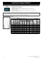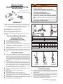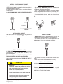
1
Wire Rope End Terminations d nE e p o R e r i W Wire Rope End Termina tions s n o i ta n i mr e T Copyright © 2002 The Crosby Group, Inc. All Rights Reserved 25 Forged Wire Rope Clips What It Takes To Be G-450 G-429 ³&URVE\ 2U (TXDO´ FORGED FOR CRITICAL APPLICATIONS The proper performance of forged clips depends on proper manufacturing practices that include good forging techniques and accurate machining. Forged clips provide a greater rope bearing surface and more consistent strength than malleable cast iron clips. Fist Grip clips provide a saddle for both the “live” and the “dead” end. Fewer forged clips are required for each termination than with malleable cast iron clips. Forged clips reduce the possibility of hidden defects that are sometimes present in malleable cast iron clips. Malleable cast iron clips should only be used in non-critical applications. ANSI, OSHA, and ASTM recommend only forged clips for critical applications. FULL LINE The proper application of forged clips requires that the correct type, size, number, and installation instructions be used (See APPLICATION INFORMATION below for more information.) Availability of a full range of sizes of forged U-bolt clips and forged fist grip clips are essential for design flexibility. IDENTIFICATION The clip’s size, manufacturer’s logo, and a traceability code should be clearly embossed in the forging of the clip. These three elements are essential in developing total confidence in the product. COMPETITION Ask: is the clip forged? Ask: is an adequate cradle provided in the clip base for the wire rope? Malleable cast iron clips are sometimes improperly used as replacements for forged clips. Ask: Do they have both fist grip and U-bolt clips available? Ask: Do they have a full range of forged wire rope clip sizes? No competitor has the full line of forged U-Bolt clips and fist grip clips that Crosby has. Ask: Is the manufacturer’s name and size of clip clearly marked? Ask: Do they have a traceability system that is actively used in the manufacturing process? Most do not have a traceability system. APPLICATION INFORMATION Detailed application information will assist you in the proper installation of wire rope clips. This information is most effective when provided at the point of application, as well as in supporting brochures and engineering information. The manufacturer must provide this specific information. Generic information will not provide all the needed application instructions. A formal application and warning system that attracts the attention of the user, clearly informs the user of the factors involved in the task, and informs the user with the proper application procedures as needed. Ask: Does each clip have the application and warning information? Most competitors do not have application and warnings information with each clip. CROSBY Crosby provides forged “Red” U-Bolt Clips and forged Fist Grip Clips which meet or exceed Federal Specification Number FF-C-450 and are considered the industry standard. Only Crosby provides forged “Red” U-Bolt Clips from 1/8" to 3-1/2"* and forged Fist Grip Clips from 3/16" through 1-1/2". * The 3-1/2" base is a steel casting. Crosby clearly embosses its logo, the size, and the Product Identification Code (PIC) into all Crosby “Red” U-bolt Clip bases and Fist Grip clips. Crosby’s traceability system is actively used throughout the manufacturing of forged clips. The material analysis for each heat of steel, is verified within our own laboratory. Crosby provides detailed application and warning information for all forged clips. Each clip is individually bagged or tagged with the application and warning information. Testing and evaluation of special applications can be performed upon special request. Remember, “When buying Crosby, you’re buying more than product, you’re buying Quality.” 26 Copyright © 2002 The Crosby Group, Inc. All Rights Reserved Wire Rope End Terminations &URVE\ 9DOXH $GGHG )XOO /LQH &URVE\ SURYLGHV ERWK IRUJHG ³5HG´ 8%ROW &OLSV DQG IRUJHG )LVW *ULS &OLSV )RUJHG &URVE\ ³5HG´ 8%ROW &OLSV KDYH IRUJHG EDVHV RQ DOO VL]HV H[FHSW WKH EDVH LV D VWHHO FDVWLQJ 7KH HQWLUH FOLS LV JDOYDQL]HG WR UHVLVW FRUURVLYH DQG UXVWLQJ DFWLRQ &OLS VL]HV WKURXJK KDYH 8%ROWV ZLWK UROOHG WKUHDGV ZKLFK HQKDQFH WKH VWUHQJWK RI WKH PDWHULDO DQG IDWLJXH SURSHUWLHV )RUJHG )LVW *ULS &OLSV DUH IRUJHG DQG WKH HQWLUH FOLS LV JDOYDQL]HG 7KH GRXEOH VDGGOH GHVLJQ HOLPLQDWHV WKH SRVVL ELOLW\ RI LQFRUUHFW LQVWDOODWLRQ 'HVLJQHG DV DQ LQWHJUDO SDUW RI WKH FOLS WKH EROWV DUH RSSRVLWH RQH DQRWKHU VHH * H[DPSOH EHORZ $V UHVXOW WKH QXWV FDQ EH LQVWDOOHG LQ VXFK D ZD\ DV WR HQDEOH WKH RSHUDWRU WR VZLQJ WKH ZUHQFK LQ D IXOO DUF IRU HDVH RI LQVWDOODWLRQ $SSOLFDWLRQ ,QIRUPDWLRQ $SSOLFDWLRQ DQG ZDUQLQJ LQIRUPDWLRQ LV DYDLODEOH IRU ERWK &URVE\ ³5HG´ 8%ROW &OLSV DQG )LVW *ULS &OLSV 7KH &URVE\ :DUQLQJ 6\VWHP LV GHVLJQHG WR DWWUDFW WKH DWWHQWLRQ RI WKH XVHU FOHDUO\ LQIRUP WKH XVHU RI WKH IDFWRUV LQYROYHG LQ WKH WDVN DQG SURYLGH WKH XVHU ZLWK SURSHU DSSOLFDWLRQ SURFHGXUHV (DFK &URVE\ ³5HG´ 8%ROW &OLS DQG )LVW *ULS &OLS LV HLWKHU EDJJHG RU WDJJHG ZLWK DSSURSULDWH DSSOLFDWLRQ DQG ZDUQ LQJ LQIRUPDWLRQ WKXV HQVXULQJ WKDW WKH LQIRUPDWLRQ LV DYDLODEOH DW WKH SRLQW RI DSSOLFDWLRQ IRU HDFK DQG HYHU\ FOLS GXULQJ LQVWDOODWLRQ 0DWHULDO $QDO\VLV &URVE\ FDQ SURYLGH FHUWLILHG PDWHULDO PLOO DQDO\VLV IRU HDFK SURGXFWLRQ ORW WUDFHDEOH E\ WKH 3URGXFW ,GHQWLILFDWLRQ &RGH 3,& &URVE\ WKURXJK LWV RZQ ODERUDWRU\ YHULILHV WKH DQDO\VLV RI HDFK KHDW RI VWHHO 7HVWLQJ &URVE\ SHULRGLFDOO\ DXGLWV WKH WHUPLQDWLRQ HIILFLHQFLHV RI WKH ³5HG´ 8%ROW &OLSV DQG )LVW *ULS &OLSV 8SRQ VSHFLDO UHTXHVW &URVE\ ZLOO GHWHUPLQH WKH HIILFLHQFLHV RI FOLS DVVHPEOLHV ZKHQ DSSOLHG WR VSHFLDO URSH FRQ VWUXFWLRQV DQG VSHFLDO DSSOLFDWLRQV G-450 Red-U-Bolt®, Clip Copyright © 2002 The Crosby Group, Inc. All Rights Reserved G-429 Fist Grip Clip 27 Forged Wire Rope Clips SEE APPLICATION AND WARNING INFORMATION On Page 46 G-450 • Each base has a Product Identification Code (PIC) for material traceability, the name CROSBY or CG, and a size forged into it. • Sizes 1/8" through 2-1/2" (3 mm through 76mm) have forged bases. • Entire Clip-Galvanized to resist corrosive and rusting action • Only Genuine Crosby clips have a Red U-BOLT ® for instant recognition. • All Clips are individually bagged or tagged with proper application instructions and warning information. • Clip sizes up through 1-1/2" (38mm) have rolled threads. • Look for the Red-U-Bolt®, your assurance of Genuine Crosby Clips. s p i l C e p o R e r i W d e g r o F Crosby Clips, all sizes 1/4" (6 mm) and larger, meet the performance requirements of Federal Specification FF-C-450 TYPE 1 CLASS 1, except for those provisions required of the contractor. G-450 Crosby ® Clips Rope Size (mm )* * 3-4 *5 6-7 8 9-10 11 12-13 14-15 16 18 20-22 24-26 28-30 32-34 36 38 41-42 44-46 48-52 56-58 62-65 ** 68-72 75-78 ** 85-90 eader 450H N S G-450 Stock No. 1010015 1010033 1010051 1010079 1010097 1010113 1010131 1010159 1010177 1010195 1010211 1010239 1010257 1010275 1010293 1010319 1010337 1010355 1010373 1010391 1010417 1010435 1010453 1010426 Std. Packag e Qty. 100 100 100 100 100 50 50 50 50 25 25 10 10 10 10 10 Bulk Bulk Bulk Bulk Bulk Bulk Bulk Bulk Weigh t Per 100 (kg ) 2.72 4.54 8.62 12.7 21.8 35.4 36.3 49.4 49.9 64 96 114 128 199 200 247 319 424 590 726 862 1043 1406 1814 A 5.60 6.35 7.85 9.65 11.2 12.7 12.7 14.2 14.2 15.7 19.1 19.1 19.1 22.4 22.4 22.4 25.4 28.7 31.8 31.8 31.8 31.8 38.1 38.1 B 18.3 24.6 26.2 35.1 38.1 47.8 47.8 57.0 60.5 70.0 79.0 89.0 98.5 108 118 125 135 146 164 181 195 211 233 273 Dimensions (mm ) D E 11.9 10.4 15.0 12.7 19.1 16.8 22.4 18.3 25.4 23.1 30.2 26.2 30.2 28.7 33.3 31.0 33.3 34.0 38.1 35.8 44.5 40.4 47.8 45.2 51.0 48.5 58.5 55.5 60.5 58.5 66.5 62.0 70.0 67.5 77.5 74.5 86.0 83.5 98.5 81.0 105 93.5 111 124 121 119 140 152 C 11.2 14.2 12.7 19.1 19.1 25.4 25.4 31.8 31.8 36.6 41.1 46.0 51.0 54.0 58.5 60.5 66.5 70.0 76.0 81.0 87.5 90.5 98.5 114 F 9.65 11.2 14.2 17.5 19.1 22.4 22.4 23.9 23.9 26.9 31.8 31.8 31.8 36.6 36.6 36.6 41.4 46.0 51.0 51.0 51.0 51.0 60.5 60.5 G 20.6 23.9 30.2 33.3 41.4 46.0 48.5 52.5 52.5 57.0 62.0 67.0 71.5 79.5 79.5 86.5 92.0 97.0 113 114 103 127 149 157 H 23.9 29.5 36.6 42.9 49.3 58.0 58.0 63.5 63.5 72.0 80.5 88.0 91.0 105 106 113 121 134 149 162 168 175 194 213 G 20.6 23.9 30.2 41.4 48.5 52.5 H 23.9 29.5 36.6 49.3 58.0 63.5 * Electr o-plated U-Bolt and Nuts. ** 70 mm and 89mm base is made of cast steel. SS-450 • Each base has a Product Identification Code (PIC) for material traceability, the name CROSBY or CG, and a size forged into it. • Entire clip is made from 316 Stainless Steel to resist corrosive and rusting action. • All components are Electro-Polished. • All Clips are individually bagged or tagged with proper application instructions and warning information. s Rope Size (m m) 3-4 5 6-7 9-10 12-13 16 28 s450Headr N S SS-450 Stock No. 1011250 1011261 1011272 1011283 1011305 1011327 Std. Package Qty. Bulk Bulk Bulk Bulk Bulk Bulk p i l C Weight Per 100 (kg) 2.72 4.54 9.07 21.3 34.9 48.1 e p o R e r i W S S A 5.60 6.35 7.85 11.2 12.7 14.2 B 18.3 24.6 26.2 38.1 47.8 60.5 C 11.2 14.2 12.7 19.1 25.4 31.8 Dim en sions (mm) D E 11.9 10.4 15.0 12.7 19.1 16.8 25.4 23.1 30.2 28.7 33.3 34.0 F 9.65 11.2 14.2 19.1 22.4 23.9 Copyright © 2002 The Crosby Group, Inc. All Rights Reserved SEE APPLICATION AND WARNING INFORMATION On Page 47 NEW STYLE FIST GRIP CLIPS 5 MM - 16 MM • Bolts are an integral part of the saddle. Nuts can be installed in such a way as to enable the operator to swing the wrench in a full arc for fast installation. • All sizes have forged steel saddles. • Entire clip is Galvanized to resist corrosive and rusting action. • All Clips are individually bagged or tagged with proper application instructions and warning information. • Assembled with standard heavy hex nuts. s p i l C e p o R e r i W ® p i r G FIST GRIP® CLIPS 19 MM - 38 MM t s i F Fist Grip wire clip s meet or exceed t he performance requirem ents of Federal Specification FF-C-450 Typ e III, Class 1, except for t hose provisions required of t he contract or. 429Headr N S Rop e Size (m m)* 5-7 8 10 11-13 14-16 18-20 22 24-26 28-30 32-34 36-40 G-429 Sto ck No . 1010471 1010499 1010514 1010532 1010550 1010578 1010596 1010612 1010630 1010658 1010676 Std. Package Qty. 100 100 50 50 50 25 25 10 10 10 Bulk Weig ht Per 100 (kg ) 10.4 12.7 18.1 28.1 46.7 79 102 136 181 181 318 C 10.2 11.9 13.0 15.0 18.3 21.8 24.6 28.7 32.5 34.0 39.6 D 23.9 26.9 26.9 31.8 38.1 46.0 53.8 57.0 60.5 63.5 76.0 Dim ensions (mm ) E 9.65 9.65 11.2 12.7 16.0 19.1 19.1 19.1 22.4 22.4 25.4 G 32.5 37.3 46.0 55.5 68.5 74.5 84.0 94.5 107 108 141 N 36.6 39.1 45.2 54.6 65.3 67.8 72.6 77.7 87.4 90.4 105 * S izes through 16mm incorporate New Style design. Copyright © 2002 The Crosby Group, Inc. All Rights Reserved 29 Wire Rope End Termina tions Fist Grip® Wire Rope Clips S-421T Wedge Sockets SEE APPLICATION AND WARNING INFORMATION On Page 48 S-421T Wedge sockets meet the p erformance requ irement s of Federal Spec ification RR-S-550D, T yp e C, except those provisions requ ired of the contractor. • Basket is cast steel. • Individually magnetic particle inspected. • Pin diameter and jaw opening allows wedge and socket to be used in conjuction with open swage and spelter sockets. • Secures the tail or "dead end" of the wire rope to the wedge, thus eliminates loss or "Punch out" of the wedge. • Eliminates the need for an extra piece of rope, and is easily installed. • The TERMINATOR™wedge eliminates the potential breaking off of the tail due to fatigue. • The tail, which is secured by the base of the clip and the wedge, is left undeformed and available for reuse. • Incorporates Crosby’s patented QUIC-CHECK® "Go" and "No-Go" feature cast into the wedge. The proper size rope is determined when the following criteria are met: • 1) The wire rope should pass thru the "Go" hole in the wedge. • 2) The wire rope should NOT pass thru the "No-Go" hole in the wedge. • Utilizes standard Crosby Red-U-Bolt® wire rope clip. • Wedge socket terminations have an efficiency rating of 80% based on the catalog strength of XXIP wire rope. • Standard S-421 wedge socket can be retrofitted with the new style TERMINATO R™ wedge. • Available with Bolt, Nut, and Cotter Pin. • U.S. patent 5,553,360 and foreign equivalents. s t e k c o S e g d e W T 1 2 4 - S S-421T Wedge Sockets Wire Rope Dia. (mm.) * 9-10 11-13 14-16 18-19 20-22 24-26 28 30-32 SN eadr H 421T S-421T Sto ck No.* 1035000 1035009 1035018 1035027 1035036 1035045 1035054 1040448 Wedge S-421T W Only Weigh t Sto ck No . Weig ht Each Wed ge Each (kg.) Only (kg ) 1.44 1035555 .23 2.79 1035564 .48 4.40 1035573 .81 6.58 1035582 1.18 9.75 1035591 1.82 13.9 1035600 2.44 20.5 1035609 3.56 26.1 1040607 3.09 Dimensions (mm ) A 143 173 207 248 283 324 365 406 B 70.5 90.0 111 122 118 129 140 202 C 20.6 25.4 31.8 38.1 44.5 51.0 57.0 63.5 D 20.6 25.4 30.2 35.1 41.4 51.0 57.0 63.5 G 35.1 41.1 54.0 62.0 68.5 65.0 84.0 90.5 H 79.0 98.0 116 136 160 178 197 N/A J† 187 222 263 306 356 403 450 N/A K† 40.6 30.7 41.7 55.0 56.5 69.0 63.5 86.0 L 22.4 26.9 31.0 35.6 42.2 51.0 57.0 63.5 P 39.6 49.3 57.0 66.5 79.0 95.5 108 121 R 11.2 12.7 14.2 16.8 19.1 22.4 25.4 28.4 S 54.1 62.0 79.5 92.2 106 118 137 148 T 11.2 13.5 17.5 19.8 22.4 26.2 30.2 33.3 U 31.8 44.5 51.0 59.5 68.5 73.0 79.5 86.0 V 35.1 47.8 55.5 65.0 74.5 83.5 90.5 97.0 * TERMINATOR™Assembly includes S ocket, Wedge, Pin and Wire Rope Clip. ** 1-1/4" not available in TERMINATOR™S tyle. † Nominal NOTE: For intermediate wire rope sizes, use next larger size socket. 30 Copyright © 2002 The Crosby Group, Inc. All Rights Reserved Wire Rope End Termina tions US-422T Utility Wedge Sockets SEE APPLICATION AND WARNING INFORMATION On Page 49 US-422T • Basket is cast steel. • Cast into each socket is the name "McKissick", "Crosby" or "CG", its model number and its wire line range. • By simply changing out the wedge, each socket can be utilized for various wire line sizes (Ensure correct wedge is used for wire rope size). • Wedges are color coded for easy identification. • Blue - largest wire line size for socket. • Black - mid size wire line for socket. • 11 mm on US4 • 14 mm on US5 • Orange - smallest wire line size for socket. Select ed sizes now incorporate th e "TE RMINATOR"™ design. • Cast into each wedge is the model number of the socket and the wire line size for which the wedge is to be used. • Load pin is forged and headed on one end. • US-422 wedge sockets contain a hammer pad (lip) to assist in proper securement of termination. • Wedge socket terminations have an efficiency rating of 80% based on the catalog strength of XXIP wire rope. • UWO-422 Wedges are to be used only with the US-422 Wedge Socket Assemblies. s t e k c o S e g d e W y t i l i t U T 2 2 4 - S U US-422T Utility Wedge Socket Wire Rope Model Size No . (mm ) US4 10 US4 11 US4 13 US5 13 US5 14 US5 16 US6 16 US6 19 US8A 16 US8A 19 US7 22 US7 25 US8 22 US8 25 US10 28 US10 32 US11 28 US11 32 Dimension s (m m) Met 42T N S US-422T Stock No. * 1044300* 1044309* 1044318* 1044327* 1044336* 1044345* 1044354* 1044363* 1038562 1038571 1038580 1038589 1044408* 1038607 1038616 1038625 1038634 1038643 Weig ht Wedge Each On ly (kg ) Stock No.† 2.09 1047310† 2.09 1047301† 2.09 1047329† 3.86 1047338† 3.86 1047347† 3.86 1047356† 4.26 1047365† 4.26 1047374† 7.94 1046656 7.94 1046665 7.48 1046674 7.48 1046683 9.43 1047422† 9.43 1046701 21.1 1046710 21.1 1046919 25.9 1046928 25.9 1046937 Weight Each (kg) .27 .27 .27 .45 .45 .45 .64 .64 1.36 1.36 1.18 1.18 1.36 1.36 4.08 4.08 3.18 3.18 A 173 173 173 233 233 233 241 241 286 286 286 286 283 283 392 392 406 406 B 89.5 89.5 89.5 108 108 108 118 118 124 124 129 129 145 145 202 202 193 193 C 25.4 25.4 25.4 35.8 35.8 35.8 38.1 38.1 44.5 44.5 33.3 33.3 44.5 44.5 44.5 44.5 63.5 63.5 D 25.4 25.4 25.4 31.8 31.8 31.8 31.8 31.8 41.4 41.4 31.8 31.8 41.4 41.4 41.4 41.1 63.5 63.5 G 41.4 41.4 41.4 54.0 54.0 54.0 57.0 57.0 54.0 54.0 68.5 68.5 68.5 68.5 92.0 92.0 90.5 90.5 H 71.5 71.5 71.5 84.0 84.0 84.0 92.0 92.0 95.5 95.5 97.5 97.5 114 114 156 156 152 152 J 76.0 76.0 76.0 93.5 93.5 93.5 89.0 89.0 104 106 125 125 127 127 156 156 184 184 K L P 33.3 70.0 49.3 33.3 70.0 49.3 33.3 70.0 49.3 51.0 102 76.0 51.0 102 76.0 51.0 102 76.0 54.0 114 76.0 54.0 114 76.0 70.0 125 98.5 70.0 125 98.5 65.0 119 82.5 65.0 119 82.5 54.0 114 79.5 54.0 114 79.5 76.0 181 111 76.0 181 111 70.0 159 121 70.0 159 121 R 12.7 12.7 12.7 16.0 16.0 16.0 14.2 14.2 19.1 19.1 16.8 16.8 19.1 19.1 19.1 19.1 28.7 28.7 S 64.5 64.5 64.5 82.5 82.5 82.5 82.5 82.5 105 105 82.5 82.5 110 110 105 105 156 156 T 13.5 13.5 13.5 20.6 17.5 17.5 22.4 22.4 25.4 25.4 26.9 26.9 22.4 22.4 39.6 39.6 33.3 33.3 U 48.5 44.5 44.5 48.8 51.0 51.0 60.5 54.0 67.5 58.5 54.0 47.8 68.5 62.0 89.0 87.5 93.0 86.0 V 54.5 47.8 47.8 54.5 55.5 55.5 70.0 67.0 77.5 71.5 65.0 60.5 74.5 68.5 114 113 104 97.0 * US-422T "TERMINATOR"™Style. † UWO-422T "TERMINATOR"™Style Copyright © 2002 The Crosby Group, Inc. All Rights Reserved 31 Button Spelter Sockets SB-427 • Designed for use with mobile cranes. Can be used to terminate high performance, rotation resistant ropes, and standard 6 strand ropes. • Available in six sizes from 13mm to 38mm. • Button Spelter terminations have a 100% efficiency rating, based on the catalog strength of the wire rope. • Easy to install assembly utilizes Crosby® WIRELOCK® socketing compound. • Sockets and buttons are re-usable. • Replacement buttons and sockets are available. s t e k c o S r e t l e p S n o t t u B Button Spelter Sockets Wire Ro pe Size (in .) 1/2 - 5/8 5/8 - 3/4 3/4 - 7/8 7/8 - 1 1-1/8 - 1-1/4 1-3/8 - 1-1/2 (mm ) 13-16 16-19 19-23 22-26 28-32 35-38 Wire Ro pe Size (in.) 1/2 - 5/8 5/8 - 3/4 3/4 - 7/8 7/8 - 1 1-1/8 - 1-1/4 1-3/8 - 1-1/2 SB-427 Sto ck No. 1052005 1052014 1052023 1052032 1052041 1052050 sb427 (mm) 13-16 16-19 19-23 22-26 28-32 35-38 Weigh t Each (kg) 2.76 4.67 7.75 13.24 20.86 35.38 Socket Only Sto ck No . 1052107 1052116 1052125 1052134 1052143 1052152 Button Only Stock No. 1052203 1052212 1052221 1052230 1052249 1052258 Dimensions (mm ) A 183 217 254 298 351 424 B 67.6 79.2 92.0 111 127 152 C 32.5 38.8 45.2 51.6 64.3 77.0 D 30.2 35.1 41.1 51.0 57.2 69.9 WI REL OCK ® W IRE LO CK ® WIR EL OCK ® Req uired (cc) 35 60 100 140 250 420 Sto ck No . 1039602 1039602 1039602 1039602 * 1039604 1039606 K it-Size (cc) 100 100 100 100 250 500 E 31.0 36.6 42.9 51.0 63.5 79.2 F 15.7 19.1 22.4 26.2 28.2 32.3 J 38.1 44.5 52.3 61.9 74.7 91.9 K 63.5 76.2 88.9 102 127 152 * 2 kits required. 32 Copyright © 2002 The Crosby Group, Inc. All Rights Reserved G-517 / S-517 Wire Rope End Termina tions Mooring Sockets • Designed for today's higher strength classes of wire rope. • Wide range of sizes available: • 50 mm through 92 mm Wire Line • "M-Line" socket terminations have a 100% efficiency rating, based on the minimum breaking load of the wire rope. • Design of bail allows for easy connection to shackles and other connecting links. • Socket design utilizes features to keep cone from rotating. • Available Galvanized or Self Colored. s t e k c o S g n i r o o M G-517 / S-517 "M-Line" Mooring Sockets Ro pe Dia. (mm) 50-54 64-67 64-67 70-73 50-54 82-86 88-92 Copyright © 2002 The Crosby Group, Inc. All Rights Reserved g517 N S G-517 Stock No. 1005002 1005020 1005048 1005066 1005084 1005105 1005123 S-517 Sto ck N o. 1005011 1005039 1005057 1005075 1005093 1005114 1005132 Weig ht Each (kg.) 25.8 34.5 47.6 62.6 87.5 104 127 A 63.5 70.5 77.5 84.5 89.0 98.5 105 B 121 133 149 165 184 194 203 C 133 146 170 181 197 222 230 Dimension s (mm) D 178 196 217 237 262 277 298 E 53.1 58.7 68.3 76.2 82.6 88.9 93.7 F 210 233 257 282 313 334 355 G 407 455 505 549 597 654 692 33 Open Spelter Sockets G-416 / S-416 • Forged Steel Sockets thru 38 mm, cast alloy steel 40 mm thru 100 mm. • Spelter socket terminations have an efficiency rating of 100%, based on the catalog strength of wire rope. Ratings are based on recommended use with 6 x 7, 6 x 19, or 6 x 37, I PS or XIP (EIP), XXIP (EEIP), RRL, FC, or IWRC wire rope. s t e k c o S r e t l e p S n e p O Open Grooved Sockets meet the p erformance requ irement s of Federal Spec ification RR-S-550D, T yp e A, except for those provisions requ ired of the contractor. NOTICE: All cast steel sockets 40 mm and larger are magnetic particle inspected and ultrasonic inspected. Proof testing available on special order. Drawing illustrates one groove used on sockets 6 mm thru 19 mm. Sizes 22 mm thru 38 mm use 2 grooves. Sizes 40 mm and larger use 3 grooves. G-416 / S-416 Open Spelter Sockets Ro pe Dia. (mm )* 6-7 8-10 11-13 14-16 18 20-22 24-26 28-30 32-35 38 * 40-42 * 44-48 * 50-54 * 56-60 * 64-67 * 70-73 * 75-80 * 82-86 * 88-92 * 94-102 Structural Stran d Dia. (mm) 12-13 14-16 18-19 20-22 24-26 28 30-32 33-35 36-40 42-45 46-48 50-54 56-62 64-67 70-73 76-80 - Stock G-416 Galv. 1039619 1039637 1039655 1039673 1039691 1039717 1039735 1039753 1039771 1039799 1039815 1039833 1039851 1039879 1041633 1041651 1041679 1041697 1041713 1041731 SN eader g416H No. S-416 S.C. 1039628 1039646 1039664 1039682 1039708 1039726 1039744 1039762 1039780 1039806 1039824 1039842 1039860 1039888 1041642 1041660 1041688 1041704 1041722 1041740 Weigh t Each (kg) .50 .59 1.02 1.63 2.64 4.38 7.03 9.75 14.1 21.4 24.9 37.2 59 76 114 143 172 197 255 355 Dimensions (mm ) A 116 123 141 171 202 235 268 300 335 384 413 464 546 597 648 692 737 784 845 921 C 19.1 20.6 25.4 31.8 38.1 44.5 51.0 57.0 63.5 76.0 76.0 89.0 102 114 127 133 146 159 171 191 D 17.5 20.6 25.4 30.2 35.1 41.4 51.0 57.0 63.5 70.0 76.0 89.0 95.5 108 121 127 133 140 152 178 F 9.65 12.7 14.2 17.5 20.6 23.9 28.7 31.8 38.1 41.4 44.5 51.0 57.0 63.5 73.0 79.0 86.0 92.0 98.5 108 G 17.5 20.6 23.9 28.7 31.8 38.1 44.5 51.0 57.0 70.0 76.0 79.5 95.5 102 114 124 133 146 165 184 H 39.6 42.9 47.8 57.0 66.5 82.5 95.5 105 121 133 140 162 187 210 235 267 282 302 314 346 J 57.0 57.0 63.5 76.0 89.0 102 114 127 140 152 165 191 216 229 248 279 305 330 356 381 L 39.6 44.5 51.0 63.5 76.0 89.0 102 117 127 152 165 178 229 254 274 279 287 300 318 343 M 33.3 38.1 47.8 57.0 66.5 79.5 95.5 105 121 137 146 165 178 197 216 229 241 254 274 318 N 9.10 11.2 12.7 14.2 15.7 20.3 22.4 25.4 28.7 30.2 33.3 39.6 46.0 54.0 60.5 73.0 76.0 79.0 82.5 89.0 * Cast Alloy Steel. 34 Copyright © 2002 The Crosby Group, Inc. All Rights Reserved G-417 / S-417 Wire Rope End Termina tions Closed Spelter Sockets • Forged Steel Sockets thru 38 mm, cast alloy steel 40 mm thru 100 mm. • Spelter socket terminations have an efficiency rating of 100%, based on the catalog strength of wire rope. Ratings are based on the recommended use with 6 x 7, 6 x 19 or 6 x 37, I PS or XIP (EIP) , XXIP (EEIP), RRL, FC or IWRC wire rope. s t e k c o S r e t l e p S d e s o l C Closed grooved Sockets meet the p erformance requiremen ts of Federal Specification RR-S-550D, T ype B, except for those provisions requ ired of the contractor. NOTICE: All cast steel sockets 40 mm and larger are magnetic particle inspected and ultrasonic inspected. Proof testing available on special order. Drawing illustrates one groove used on sockets 6 mm thru 19 mm. Sizes 22 mm thru 38 mm use 2 grooves. Sizes 40 mm and larger use 3 grooves. G-417 / S-417 Closed Spelter Sockets Ro pe Dia. (m m) † 6-7 8-10 11-13 14-16 18 20-22 24-26 28-30 32-35 38 † 40-42 † 44-48 † 50-54 † 56-60 † 64-67 † 70-73 † 75-80 † 82-86 † 88-92 † 94-102 Structural Strand Dia. (mm) 12-13 14-16 18-19 20-22 24-26 28 30-32 33-35 36-40 42-45 46-48 50-54 56-62 64-67 70-73 76-80 - S tock G-417 Galv. 1039897 1039913 1039931 1039959 1039977 1039995 1040019 1040037 1040055 1040073 1040091 1040117 1040135 1040153 1041759 1041777 1041795 1041811 1041839 1041857 g417H N S eadr No . S-417 S.C. 1039904 1039922 1039940 1039968 1039986 1040000 1040028 1040046 1040064 1040082 1040108 1040126 1040144 1040162 1041768 1041786 1041802 1041820 1041848 1041866 Weight Each (kg) .23 .34 .68 1.13 1.92 3.28 4.76 6.46 8.95 13.24 16.32 25.96 35.83 47.62 63.50 99.79 125 142 181 246 Dim en sions (mm) A 116 125 140 162 194 226 254 283 309 355 390 445 502 556 597 645 686 743 787 845 B 12.7 15.8 17.5 20.6 26.9 33.3 36.6 39.6 41.4 49.3 54.0 55.5 62.0 73.0 79.5 79.5 82.5 102 102 108 C 39.6 42.9 51.0 67.0 76.2 92.0 105 114 128 137 146 171 194 216 241 273 292 311 330 362 D* 22.4 24.6 29.5 35.8 42.2 48.7 58.5 65.0 71.0 81.0 82.5 95.5 111 127 140 159 171 184 197 216 F 9.65 12.7 14.2 17.5 20.6 24.6 28.7 31.8 38.1 41.4 44.5 51.0 57.2 63.5 74.5 79.5 86.0 92.0 98.5 108 G 17.5 20.6 23.9 30.2 33.3 38.1 44.5 51.0 58.5 70.5 76.2 79.5 95.5 102 114 124 133 146 165 184 H 39.6 42.9 51.0 67.0 70.0 82.5 95.5 105 119 132 140 162 187 210 235 259 292 311 330 362 J 57.2 57.2 63.5 76.2 89.0 102 114 127 138 151 165 191 216 229 248 279 305 330 356 381 K 12.7 17.5 22.4 25.4 31.8 38.1 44.5 51.0 56.5 62.5 70.0 76.2 82.5 92.0 102 124 133 146 159 178 L 46.0 52.5 58.5 65.0 77.5 90.5 103 116 129 155 171 198 224 254 270 286 298 311 330 356 * Diam eter of pin must not exceed pin used on companion 416 socket. Reference adjacent page "D" dim ension. † Cast Alloy Steel. Copyright © 2002 The Crosby Group, Inc. All Rights Reserved 35 National Steel Swaging Sleeves S-505 The National Die Guide will assist you in selecting the proper dies to meet your swaging needs. • • • • • • For Flemish eye wire rope splicing. Designed for low temperature toughness. Resists cracking when swaged (equals or exceeds stainless steel sleeves). Special processed low carbon steel. “Cold Tuff ®” for better swageability. Can be stamped for identification after swaging without concern for fractures when following these directions. Use round corner stamps to a maximum depth of 0.4 mm.The area for stamping should be on the side of the sleeve in the plane of the sling eye, and no less than 6 mm from either end of the sleeve. • Standard Steel Sleeve terminations have efficiency ratings as follows based on the catalog strength of wire rope. S-505 Termination Efficiency Type of Wire Rope * Size (mm) IWRC FC 6 - 25 96% 93% 28 - 52 92% 89% 54 and Larger 90% 87% * NOTE: S-505 Standard Sleeves are recommended for use with 6 x 19 or 6 x 37, IPS or XIP (EIP), XXIP (EEIP), RRL, FC or IWRC wire rope. Before using any National Swage fitting with any other type lay, construction or grade of wire rope, it is recommended that the termination be destructive tested and documented to prove the adequacy of the assembly to be manufactured. “Cross Section of Swaged Sleeve” NOTE: See Page 37 for dimensional information For additional swaging information, please refer to the National Swaging Brochure. 36 Copyright © 2002 The Crosby Group, Inc. All Rights Reserved National Steel Swaging Sleeves l S g n i g a wS l e e t S l a n o i t a N Wire Rope End Termina tions s e v e e S-505 "COLD-TUFF" Standard Steel Sleeves S-505 Standard Steel Sleeve Sp ecifications Before Swag e Dimensions (mm) Ns50H S eadr 1 Press/ Die Data Ns50H S eadr 2 S-505 Sto ck No . 1041063 1041090 1041107 1041125 1041143 1041161 1041189 1041205 1041223 1041241 1041269 R ope Weight Size Per 100 (mm) (kg) 6-7 3.60 8 4.08 9-10 5.44 11 13.6 13 13.2 14 30.8 16 25.9 18-19 40.0 22 62 25-26 89 28-29 118 1041287 31-32 1041303 34-35 1041321 37-38 1041349 44-45 1041367 50-52 1041385 56-57 1041401 62-64 1041429 68-70 1041447 75-76 1041483 87-89 1041492 93-95 1041508 1041526 154 195 159 367 510 862 1043 1270 1334 2105 2495 100105 3130 112114 4536 Pkg. Qty. 250 200 100 50 50 25 25 20 10 10 Bulk Bulk Bulk Bulk Bulk Bulk Bulk Bulk Bulk Bulk Bulk Bulk Bulk Bulk A 25.4 38.1 38.1 51.0 51.0 70.0 70.0 81.0 90.5 102 122 132 148 159 184 216 243 267 292 305 356 381 406 457 B 16.8 23.1 23.1 31.0 31.0 37.3 37.3 43.7 51.5 58.0 63.5 70.5 76.0 82.5 97.5 111 128 140 146 162 178 191 206 232 Copyright © 2002 The Crosby Group, Inc. All Rights Reserved D 7.88 9.66 11.9 13.5 16.0 17.8 19.1 23.1 26.2 29.5 32.5 36.5 39.7 42.9 49.2 57.0 63.5 70.0 76.0 82.5 98.5 103 111 124 E 7.12 11.2 9.91 16.5 14.2 16.0 16.0 21.3 25.4 28.6 31.8 35.8 39.7 42.9 50.0 57.0 64.5 71.5 78.5 86.0 3.94 108 114 129 G 11.9 15.8 16.8 21.6 23.1 26.2 27.7 32.5 38.9 43.7 49.3 55.0 60.5 67.0 79.5 92.0 102 114 121 133 148 160 173 195 Maximu m After Swage Dimension s (mm) 14.5 19.1 19.1 25.7 25.7 31.5 31.5 37.1 42.7 49.0 54.1 58.9 64.0 69.0 78.7 90.4 105 114 119 126 147 158 170 189 Die Desc. 1/4 T aper 3/8 T aper 3/8 T aper 1/2 T aper 1/2 T aper 5/8 T aper 5/8 T aper 3/4 T aper 7/8 T aper 1 T aper 1-1/8 Open 1st Stage 2nd Stage 1-1/4 Open 1st Stage 2nd Stage 1-3/8 Open 1st Stage 2nd Stage 1-1/2 Open 1st Stage 2nd Stage 1-3/4 Open 1st Stage 2nd Stage 2 Open 1st Stage 2nd Stage 2-1/4 Open 1st Stage 2nd Stage 2-1/2 Open 1st Stage 2nd Stage 2-3/4 Open 1st Stage 2nd Stage 3 Open 1st Stage 2nd Stage 3-1/2 Open 1st Stage 2nd Stage 3-3/4 Open 1st Stage 2nd Stage 4 Open 1st Stage 2nd Stage 4-1/2 Open 1st Stage 2nd Stage 500 Ton s 1000 Ton s 1500 Ton s 5x7 1197528 1192364 1192364 1192408 1192408 1192444 1192444 1192462 1192480 1192505 Stock N o. Fron t Lo ad 1500 ton 6x12 - Side Load 3000 ton 1500 ton 3000 ton 6x12 6x12 6x12 - 1192523 1192541 - - - - - - - - - - - - - - - - - - - - 1191089 1191043 1191089 1191043 1191061 1191089 1191061 1191089 1195370 1195469 1195076 1195085 1191034 1191052 1191034 1191052 1195389 1195478 1195094 1195101 1193201 1193229 - 1193201 1193229 1195398 1195487 - 1195110 1195129 1192621 1192587 1192667 1192621 1192649 1192667 1192685 1192701 1192729 1192747 1192765 1192783 - 1195085 1195067 - - - 1193247 1193265 - - 1195138 1195147 - 1191114 1191132 - - 1195263 1195272 - 1191150 1191178 - - 1195156 1195165 - 1191187 1191203 1195174 1195183 37 Open Swage Sockets S-501 • Forged from special bar quality carbon steel, suitable for cold forming. • Hardness controlled by spheroidize annealing. • Swage Socket terminations have an efficiency rating of 100% based on the catalog strength of wire rope. • Stamp for identification after swaging without concern for fractures (as per directions in National Swaging Brochure). • Swage sockets incorporate a reduced machined area of the shank which is equivalent to the proper after Swage dimension. Before swaging, this provides for an obvious visual difference in the shank diameter. After swaging, a uniform shank diameter is created allowing for a QUIC-CHECK® and permanent visual inspection opportunity. • Designed to quickly determine whether the socket has been through the swaging operation and assist in field inspections, it does not eliminate the need to perform standard production inspections which include gauging for the proper after swage dimensions or proof loading. • U.S. Patent 5,152,630 and foreign equivalents. s t e k c o S e g a w S n e p O NOTE: S-501 Swage Sockets are recommended for use with 6 x 19 or 6 x 37, IPS or XIP (EIP), XXIP (EEIP), RRL, FC or IWRC wire rope. Before using any National Swage fitting with any other type lay, construction or grade of wire rope, it is recommended that the termination be destructive tested and documented to prove the adequacy of the assembly to be manufactured. In accordance with ANSI B30.9, all slings terminated with swage sockets shall be proof loaded.* S-501 Open Swage Sockets S-501 Open So cket Specificatio ns Befo re Swage Dimen sio ns Rop e S-501 Size Weigh t Stock (m m) Each * No. (kg) 1039021 6-7 0.24 1039049 8 0.51 A 122 159 B 12.7 19.6 C 35.1 41.1 D 17.5 20.6 E 6.85 8.65 F 54.0 81.0 H 17.5 20.6 L 102 135 M 9.65 11.9 N 38.1 44.5 1039067 s501 N S 9-10 0.59 159 19.6 41.1 20.6 10.4 81.0 20.6 135 11.9 44.5 1039085 11-12 0.94 198 24.9 51.0 25.4 12.2 108 25.4 170 14.2 51.0 1039101 13 0.94 198 24.9 51.0 25.4 14.0 108 25.4 170 14.2 51.0 1039129 14 2.12 241 31.8 60.5 30.2 15.5 135 31.8 207 17.3 57.0 1039147 16 2.05 241 31.8 60.5 30.2 17.0 135 31.8 207 17.3 57.0 1039165 1039183 1039209 1039227 1039245 1039263 1039281 1039307 1042767 18-20 22 24-26 28 32 34-36 38-40 44 48-52 3.62 5.23 8.07 11.5 16.1 19.8 26.5 40.3 66 294 341 393 440 484 532 581 676 799 39.4 43.2 50.5 57.0 64.5 71.0 78.0 86.0 100 70.0 79.5 93.5 103 114 127 140 170 203 35.1 41.1 51.0 57.0 63.5 63.5 70.0 89.0 95.5 20.3 23.9 26.9 30.2 33.8 36.8 40.1 47.2 53.5 162 189 216 243 270 297 324 378 432 38.1 44.5 51.0 57.0 63.5 63.5 76.0 89.0 102 254 295 340 381 419 461 502 584 683 19.8 23.9 26.9 30.2 31.0 35.1 42.9 53.5 60.0 70.0 82.5 95.5 108 121 133 146 171 203 Press / Die Data Sto ck No . Sid e L oad Max. 500 1500 After 1000 1500 3000 3000 Swag e 1500 Die To n Ton To n Dim. To n 6 x 12 6 x 12 6 x 12 (m m) D escriptio n 5x7 11.7 1/4 Socket 1192845 18.0 5/16-3/8 1192863 Socket 18.0 5/16-3/8 1192863 Socket 23.1 7/16-1/2 1192881 Socket 23.1 7/16-1/2 1192881 Socket 29.5 9/16-5/8 1192907 Socket 29.5 9/16-5/8 1192907 Socket 36.1 3/4 Socket 1192925 39.4 7/8 Socket 1192949 45.7 1 Socket 1192961 52.0 1-1/8 Socket 1192989 58.5 1-1/4 Socket 1193005 65.0 1-3/8 Socket 1193023 71.5 1-1/2 Socket 1193041 1191267 1195355 1195192 77.5 1-3/4 Socket 1193069 1191276 1195367 1195209 90.5 2 Socket 1193087 1191294 1195379 1195218 * Maximum Proof Load shall not ex ceed 50% of XXIP rope catalog br eaking strength. 38 Copyright © 2002 The Crosby Group, Inc. All Rights Reserved S-502 Wire Rope End Termina tions Closed Swage Sockets • Forged from special bar quality carbon steel, suitable for cold forming. • Hardness controlled by spheroidize annealing. • Swage Socket terminations have an efficiency rating of 100% based on the catalog strength of wire rope. • Stamp for identification after swaging without concern for fractures (as per directions in National Swaging Brochure). • Swage sockets incorporate a reduced machined area of the shank which is equivalent to the proper after Swage dimension. Before swaging, this provides for an obvious visual difference in the shank diameter. After swaging, a uniform shank diameter is created allowing for a QUIC-CHECK® and permanent visual inspection opportunity. • Designed to quickly determine whether the socket has been through the swaging operation and assist in field inspections, it does not eliminate the need to perform standard production inspections which include gauging for the proper after swage dimensions or proof loading. • U.S. Patent 5,152,630 and foreign equivalents. s t e k c o S e g a wS d e s o l C NOTE: S-502 Swage Sockets are recommended for use with 6 x 19 or 6 x 37, IPS or XIP (EIP), XXIP (EEIP), RRL, FC or IWRC wire rope. Before using any National Swage fitting with any other type lay, construction or grade of wire rope, it is recommended that the termination be destructive tested and documented to prove the adequacy of the assembly to be manufactured. In accordance with ANSI B30.9, all slings terminated with swage sockets shall be proof loaded.* S-502 Closed Swage Sockets S-502 Closed Socket Sp ecifications Before Swag e Dim ensions s502 N S S-502 Stock No. 1039325 1039343 1039361 1039389 1039405 1039423 1039441 1039469 1039487 1039502 1039520 1039548 1039566 1039584 1039600 1042589 Rope Weight Size Each (m m)* (kg) 6 0.15 8 0.34 9-10 0.33 11-12 0.64 13 0.64 14 1.32 16 1.29 18-20 2.27 22 3.08 24-26 4.72 28 6.72 32 9.78 34-36 12.9 38-40 17.3 44 23.1 48-52 40.5 A 109 138 138 176 176 220 220 261 303 344 382 430 473 511 598 702 B 12.7 19.6 19.6 24.9 24.9 31.8 31.8 39.4 43.2 50.5 57.0 64.5 71.0 78.0 86.0 100 C 35.1 41.1 41.1 51.0 51.0 60.5 60.5 73.0 79.0 92.0 102 114 127 140 159 184 D 19.1 22.4 22.4 26.9 26.9 31.8 31.8 36.6 42.9 52.5 58.5 65.0 65.0 71.5 90.5 96.5 E 6.85 8.65 10.4 12.2 14.0 15.5 17.0 20.3 23.9 26.9 30.2 33.8 36.8 40.1 47.2 53.5 F 54.0 81.0 81.0 108 108 135 135 162 189 216 243 270 297 324 378 432 H 12.7 17.0 17.0 21.8 21.8 28.7 28.7 33.3 38.1 44.5 51.0 57.0 57.0 63.5 76.0 82.5 L 89.0 114 114 146 146 184 184 219 257 292 324 365 400 432 508 584 Max. After Swag e Dim. (m m) 11.7 18.0 18.0 23.1 23.1 29.5 29.5 36.1 39.4 45.7 52.0 58.5 65.0 71.5 77.5 90.5 Die Descriptio n 1/4 Socket 5/16-3/8 Socket 5/16-3/8 Socket 7/16-1/2 Socket 7/16-1/2 Socket 9/16-5/8 Socket 9/16-5/8 Socket 3/4 Socket 7/8 Socket 1 Socket 1-1/8 Socket 1-1/4 Socket 1-3/8 Socket 1-1/2 Socket 1-3/4 Socket 2 Socket Press / Die Data Sto ck No . Side 500 1500 1000 1500 3000 1500 To n To n To n 6 x 12 6 x 12 5 x7 1192845 1192863 1192863 1192881 1192881 1192907 1192907 1192925 1192949 1192961 1192989 1193005 1193023 1193041 1191267 1193355 1193069 1191276 1195367 1193087 1191294 1195379 Load 3000 To n 6 x 12 1195192 1195209 1195218 * Maximum Proof Load shall not exceed 50% of XXIP rope catalog breaking str ength. Copyright © 2002 The Crosby Group, Inc. All Rights Reserved 39 National Swage Buttons S-409 • Special processed, low carbon steel. • "Cold Tuff®" for better swageability. • Swage Button terminations have an efficiency rating of 98% based on the catalog strength of wire rope. • Stamp for identification after swaging without concern for fractures (as per directions in National Swaging Brochure). s n o t t u B e g a wS l a n o i t a N NOTE: S-409 Buttons are recommended for use with 6 x 19 or 6 x 37, IPS or XIP (EIP), RRL, FC or IWRC wire rope. Before using any National Swage fitting with any other type lay, construction or grade of wire rope, it is recommended that the termination be destructive tested and documented to prove the adequacy of the assembly to be manufactured. S-409 COLD-TUFF® Buttons S-409 Steel Swage Button Specificatio ns Befo re Swag e Dim en sions s409 N S S-409 Stock No. 1040171 1040215 1040251 1040297 1040313 1040331 1040359 1040377 1040395 1040411 1040439 1040457 1040475 1040493 Size No . 1 SB 3 SB 5 SB 7 SB 8 SB 9 SB 10 SB 11 SB 12 SB 13 SB 14 SB 15 SB 16 SB 17 SB Rop e Weigh t Size Per 100 (mm) (kg) 3 .91 5 1.81 6-6.5 3.63 8 7.26 9-10 6.80 11 13.6 13 22.7 14 31.8 16 45.4 18-20 59 22 100 25-26 141 28-29 204 31-32 295 A 11.2 14.2 16.0 22.4 22.4 28.7 33.3 36.6 39.6 42.9 51.0 57.0 65.0 71.5 B 12.7 17.8 26.9 28.7 37.6 41.4 48.0 51.5 61.5 69.5 83.0 93.0 103 116 C 3.55 5.10 7.60 9.15 10.7 12.2 14.0 15.5 17.0 20.1 23.9 26.9 30.2 33.8 Press / Die Data After Swage Dimensions D Maximu m After Swage E DimenLength * sio ns 10.2 15.5 13.2 21.3 14.7 30.5 19.6 33.8 19.6 42.9 26.2 49.3 29.5 55.0 32.8 61.0 36.1 73.5 39.4 82.5 45.7 98.0 52.0 111 58.5 122 65.0 138 Die Desc. 1/8 - 1/4 Button 1/4 1st Stage 1/8 - 1/4 Button 3/8 1st Stage 3/8 1st stage 1/2 1st Stage 5/8 socket 9/16 -5/8 Button 9/16 -5/8 Button 3/4 1st Stage 7/8 1st Stage 1 1st Stage 1-1/8 1st Stage 1-3/8 Socket Sto ck No . 500 To ns 1000 Ton s 1500 Ton s 5 x7 1191621 1197528 1191621 1192364 1192364 1192408 1192907 1191665 1191665 1192462 1192480 1192505 1192523 1193023 * NOTE: Length is measured from outside end of termination. 40 Copyright © 2002 The Crosby Group, Inc. All Rights Reserved S-506 • For turnback wire rope splicing. • Designed for lower temperature toughness. • Resists cracking when swaged (equals or exceeds stainless steel sleeves). • Special processed low carbon steel. • "Cold Tuff®" for better swageability. • Stamp for identification after swaging without concern for fractures (as per directions in National Swaging Brochure). • Turnback terminations have efficiency ratings of 94% based on the catalog strength of wire rope. s e v e e l S x e l p u D e g a wS l a n o i t a N NOTE: S-506 Duplex sleeves are recommended for use with 6 x 19 or 6 x 37, IPS or XIP (EIP), RRL, FC or IWRC wire rope. Before using any National Swage fitting with any other type lay, construction or grade of wire rope, it is recommended that the termination be destructive tested and documented to prove the adequacy of the assembly to be manufactured. S-506 COLD-TUFF® Duplex Non-Tapered Sleeves S-506 Steel Du plex Non-Tapered Sleeve Sp ecifications Before Swage Dimensions s506 N S S-506 Stock No. 1039334 1039352 1039370 1039398 1039414 1039432 1039450 1039478 1039496 1039539 Rope Weigh t Size per 100 (mm ) (kg) 8 7.71 9-10 5.90 11 14.1 13 12.2 14 28.6 16 24.5 18-20 41.3 22 57 25-26 85 30-32 174 Copyright © 2002 The Crosby Group, Inc. All Rights Reserved Pkg. Qty. 200 100 50 50 25 25 10 10 10 Bulk A 31.8 31.8 41.4 41.4 57.0 57.0 67.0 73.0 77.5 103 B 26.9 28.4 35.8 36.6 43.7 46.7 55.0 63.5 72.0 89.0 C 20.6 20.6 25.9 25.9 31.2 32.5 38.6 44.5 51.0 63.5 D 4.85 3.55 4.85 4.05 5.85 5.10 5.85 6.85 8.40 9.65 Max. After Swage Dimen sio ns (mm) 19.6 19.6 26.2 26.2 32.8 32.8 39.4 45.7 52.0 65.0 Press / Die Data Stock N o. 500 To n 1000 To n 1500 To n Die Desc. 5x7 3/8 1st Stage 1192364 3/8 1st Stage 1192364 1/2 1st Stage 1192408 1/2 1st Stage 1192408 5/8 1st Stage 1192444 5/8 1st Stage 1192444 3/4 1st Stage 1192462 7/8 1st Stage 1192480 1 1st Stage 1192505 1-3/8 socket 1193025 41 Wire Rope End Termina tions National Swage Duplex Sleeves Shank Hooks for Swaging SEE APPLICATION AND WARNING INFORMATION On Pages 50 - 51 S-319SWG • Wide range of sizes available: • Working Load Limit: 0.35 - 14 tonnes • Wire Rope sizes: 5 mm thru 30 mm. • Utilizes standard Crosby 319N shank hooks with interlocking hook tip. Each hook has a pre-drilled cam which can be equipped with a latch. • Utilizes standard National Swage swaging dies. • Forged Carbon Steel. • Quenched and Tempered. Heat treat process allows for ease of swaging. • Design Factor of 5 to 1. • Black Oxide finish on body (Shank is uncoated). • All hooks incorporate Crosby's patented QUIC-CHECK® markings (Angle Indicators and Throat Deformation Indicators). See page 87 for detailed information. g n i g a wS r o f s k o o H k n a h S For use with 6 X 19 or 6 X 37, IPS or XIP (EIP), XXIP (EEIP), RRL, FC, or IWRC wire rope. Before using any Crosby fitting with any other type lay, construction or grade of wire rope, it is recommended that the termination be destructive tested and documented to prove the adequacy of the assembly to be manufactured. Refer to swage socket or swage button instructions in the National Swage Swaging Products and Procedures Brochure for proper swaging techniques. S-319SWG Shank Hooks for Swaging Wire Rope Size (m m) 5 6-7 8 8 9-10 11 12-13 14-15 16 18 20-22 24-26 28-30 Hoo k ID Cod e DC FC GC HC HC IC IC JC JC KC LC NC OC ** Working Load Lim it (t) * 0.4 0.7 1.1 1.1 1.6 2.1 2.8 3.5 4.3 6.2 8.3 11.0 14.0 Required Swaging Die Weight Each (kg) 0.25 0.35 0.57 0.83 0.82 1.65 1.62 3.34 3.31 5.77 7.97 14.3 24.4 N319sw S g S-319SWG Stock No. 1053002 1053011 1053020 1053039 1053048 1053057 1053066 1053075 1053084 1053093 1053100 1053119 1053128 Die Descriptio n 1/8" Button 1/4" Socket 1/4" Button 3/8" Socket 3/8" Socket 1/2" Socket 1/2" Socket 5/8" Socket 5/8" Socket 3/4" Socket 7/8" Socket 1" Socket 1-1/8" Socket Maximum After Swage Diam eter (m m) 10.2 11.7 14.7 18.0 18.0 23.1 23.1 29.5 29.5 36.1 39.4 45.7 52.1 Die Stock No. 1191621 1192845 1191621 1192863 1192863 1192881 1192881 1192907 1192907 1192925 1192949 1192961 1192989 * Minimum Ultimate Str ength is 5 times the Working Load Lim it. ** ID Code "O" is old 319 style hook. Wire R ope Size (mm) 5 6-7 8 8 9-10 11 12-13 14-15 16 18 20-22 24-26 28-30 42 Dimensions (mm ) 319sw N S g S-319SWG Sto ck No . 1053002 1053011 1053020 1053039 1053048 1053057 1053066 1053075 1053084 1053093 1053100 1053119 1053128 B 11.2 12.7 16.5 19.6 19.6 24.9 24.9 31.8 31.8 39.4 43.2 50.5 57.0 D 72.5 80.0 91.0 101 101 123 123 159 159 192 212 264 346 E 5.10 6.85 8.65 8.65 10.4 12.2 14.0 15.5 17.0 20.3 23.9 26.9 30.2 F 16.0 17.5 19.1 20.6 20.6 25.4 25.4 31.8 31.8 38.1 41.4 54.0 63.5 G 18.5 21.3 25.4 29.0 29.0 36.6 36.6 46.2 46.2 57.5 66.0 76.5 92.0 H 20.6 23.9 29.5 33.3 33.3 41.4 41.4 52.5 52.5 67.0 74.7 89.0 117 J 23.6 24.6 26.9 30.2 30.2 38.1 38.1 45.2 45.2 61.0 66.5 86.5 102 K 16.0 18.0 22.4 23.9 23.9 33.3 33.3 42.2 42.2 47.8 55.5 68.5 76.0 L 132 145 162 182 182 221 221 267 267 321 345 427 586 M 16.0 18.0 22.4 23.9 23.9 28.7 28.7 36.6 36.6 41.4 49.3 60.5 76.0 O 23.6 24.6 26.9 29.5 29.5 35.8 35.8 42.9 42.9 56.4 61.2 81.0 82.6 P 49.8 56.5 62.0 70.5 70.5 88.0 88.0 117 117 133 145 175 223 R 60.5 67.0 70.0 81.5 81.5 99.5 99.5 123 123 152 165 211 240 Y 51.0 73.0 63.5 70.0 70.0 82.5 82.5 95.5 95.5 108 111 137 248 AA 38.1 51.0 51.0 51.0 51.0 63.5 63.5 76.0 76.0 102 102 102 165 Copyright © 2002 The Crosby Group, Inc. All Rights Reserved National Hydraulic Swaging Machines National offers the highest quality and most complete line of Hydraulic Swaging Machines specifically designed to be used to swage fittings on wire rope. 3 Capacities to Fit your Requirements • 500 Tonnes • 1000 Tonnes • 1500 Tonnes SEE APPLICATION AND WARNING INFORMATION On Pages 54 - 55 The following features of National Hydraulic Swaging Machines offer a number of advantages for high production sling shops: • A dual hydraulic system which combines the use of high speed and low pressure to bring dies into position; and the low speed and high pressure necessary for ideal swaging control. Adjustable tonnage control, so tonnage can be set to match die block Working Load Limit. • Four column wide stance which provides the operator ample working clearance between columns and a large area for in-process sling storage. • Vertical swage action which gives an equalized press on the fitting to produce uniform high quality. • Self locating spring locks snap the shoe-type dies into place for quick set-up and change. • The National four column wide stance Hydraulic Swaging Machines, each equipped with an up-acting ram, have two side cylinders for fast approach and return of the main ram. They come in three swaging capacities. 1500 Tonnes Hydraulic Swaging Machines Approximate weight 15.6 t. Overall height 2.6 m Fast advance and retract speed. Automatic slow, precision swaging speed. • 500 tonnes (4450 kN) • 1000 tonnes (8900 kN) • 1500 tonnes (13350 kN) Swaging Machine Capacity Chart for Swage Sleeves, Ferrules & Buttons Hydraulic Swaging Machine Swaging Size Method 500 Ton Full Die Die Size (in.) 2-1/2 x 5 Mark Series 4x7 5x7 Swaging Machine Capacity Chart for S-501 & S-502 Swage Sockets Largest Fitting Allowed to Be Swaged (mm) S-505 Sleeve S-506 S-510 S-409 Sleeve Ferrules Buttons 38 32* 14* 22* 1000 Ton Full Die 4x7 5x7 64 32* 14* 32* 1500 Ton Full Die 5x7 6 x 12 89 32* 14* 32* 3000 Ton Full Die 6 x 12 114* 32* 14* 32* Hydraulic Swaging Machine Size Swaging Method 500 Ton Full Shank 1000 Ton * Largest size fitting available. NOTE: For special applications or conditions, contact Crosby National at (501) 982-3112. 1500 Ton 3000 Ton Die Size (in.) 2-1/2 x 5 Mark Series 4x7 5x7 Largest Fitting Allowed to be Swaged (mm) 19 Progressive 4x7 5x7 32 Full Shank 4x7 8x7 26 Progressive 4x7 5x7 38 Full Shank 5x7 6 x 12 32 Progressive 5x7 6 x 12 52 Full Shank 6 x 12 52 Progressive 6 x 12 52* * Largest size fitting available. Copyright © 2002 The Crosby Group, Inc. All Rights Reserved 43 WIRELOCK® RESIN FOR SPELTER SOCKETS Note: For use on 416, 417 & 517 spelter sockets only. • 100% termination efficiency. • Temperature operating range is -54° C to +115° C. • Ideal for on site applications. • No hazardous molten metal. • Improved fatigue life. • Pouring temperature without booster pack is 9° C to 43° C. • One booster pack if pouring temperature is 0° C to 9° C. • Two booster packs if pouring temperature is -10° C to 0° C. • Refer to WIRELOCK® Technical Manual for more information. SEE APPLICATION AND WARNING INFORMATION On Pages 52 - 53 WIRELOCK® W416-7 Socket Compound Booster Pack W416-7 Kits Approvals Lloyd’s Register of Shipping Det Norske Veritas (DNV) United States Coast Guard Registro Italiano Navale Germanischer Lloyd United States Navy American Bureau of Shipping. Kit Size 100 cc 250 cc 500 cc 1000 cc 2000 cc Kits Per Case 20 12 12 12 12 Stock No. 1039602 1039604 1039606 1039608 1039610 Weight Each (kg) 0.28 0.57 1.15 2.08 4.08 Stock No. 1039603 1039605 1039607 1039609 1039611 Guide to amount of WIRELOCK® Required NATO Numbers: 100cc 8030-21-902-1823 250cc 8030-21-902-1824 500cc 8030-21-902-1825 1000cc 8030-21-902-1826 Witnessed and tested by American Bureau of Shipping. (ABS) Approximate U.S. Measurements: 250cc’s Kit 1 Cup 500cc’s Kit 1 Pint 1000cc’s Kit 1 Quart 44 Wire Rope Size WIRELOCK® Required (cc) Wire Rope Size WIRELOCK® Required (cc) 6-7 8 9-10 11 13 14 16 20 22 26 28 32 36 40 42 9 17 17 35 35 52 52 86 125 160 210 350 350 420 495 44 48 51 54 56 60 64 67 70 76 82 88 94 102 700 700 1265 1265 1410 1410 1830 1830 2250 3160 3795 4920 5980 7730 Copyright© 2002 The Crosby Group, Inc. All Rights Reserved CROSBY CLIPS WARNINGS AND APPLICATION INSTRUCTIONS G -450 (Red-U-Bolt) • • • • • • SS-450 (316 Stainless Steel) WARNING Failure to read, understand, and follow these instructions may cause death or serious injury. Read and understand these instructions before using clips. Match the same size clip to the same size wire rope. Prepare wire rope end termination only as instructed. Do not use with plastic coated wire rope. Apply first load to test the assembly. This load should be of equal or greater weight than loads expected in use. Next, check and retighten nuts to recommended torque (See Table 1, this page). Efficiency ratings for wire rope end terminations are based upon the catalog breaking strength of wire rope. The efficiency rating of a properly prepared loop or thimble – eye termination for clip sizes 3 mm through 22 mm is 80%, and for sizes 25 mm through 89 mm is 90%. The number of clips shown (see Table I ) is based upon using RRL or RLL wire rope, 6 x 19 or 6 x 37 Class, FC or IWRC; IPS or XIP, XXIP. If Seale construction or similar large outer wire type construction in the 6 x 19 Class is to be used for sizes 25 mm and larger, add one additional clip. If a pulley (sheave) is used for turning back the wire rope, add one additional clip. The number of clips shown also applies to rotation - resistant RRL wire rope, 8 x 19 Class, IPS, XIP, XXIP sizes 38 mm and smaller; and to rotation-resistant RRL wire rope, 19 x 7 Class, IPS, XIP, XXIP sizes 44 mm and smaller. For other classes of wire rope not mentioned above, we recommend contacting Crosby Engineering at the address or telephone number on the back cover to ensure the desired efficiency rating. For elevator, personnel hoist, and scaffold applications, refer to ANSI A17.1 and ANSI A10.4. These standards do not recommend U-Bolt style wire rope clip terminations. The style wire rope termination used for any application is the obligation of the user. For OSHA (Construction) applications, see OSHA 1926.251. 1. Refer to Table I in following these instructions. Turn back Figure 1 specified amount of rope from thimble or loop. Apply first clip one base width from dead end of rope. Apply U-Bolt over dead end of wire rope – live end rests in saddle (Never saddle a dead horse!). Tighten nuts evenly, alternate from one nut to the other until reaching the recommended torque. 2. When two clips are required, apply the second clip as near the Figure 2 loop or thimble as possible. Tighten nuts evenly, alternating until reaching the recommended torque. When more than two clips are required, apply the second clip as near the loop or thimble as possible, turn nuts on second clip firmly, but do not tighten. Proceed to Step 3. 46 3. When three or more clips are Figure 3 required, space additional clips equally between first two - take up rope slack - tighten nuts on each U-Bolt evenly, alternating from one nut to the other until reaching recommended torque. 4. If a pulley (sheave) is used in place of a thimble, add one additional clip. Clip spacing should be as shown. Figure 4 5. WIRE ROPE SPLICING PROCEDURES: The preferred method of splicing two wire ropes together is to use inter-locking turnback eyes with thimbles,using the recommended number of clips on each eye (See Figure 5). An alternate method is to use twice the number of clips as used for a turnback Figure 5 termination. The rope ends are placed parallel to each other, overlapping by twice th e tu r nback amount shown in the application instructions. The minimum number of clips should be Figure 6 installed on each dead end (See Figure 6). Spacing, installation torque, and other instructions still apply. 6. IMPORTANT Apply first load to test the assembly. This load should be of equal or greater weight than loads expected in use. Next, check and retighten nuts to recommended torque. In accordance with good rigging and maintenance practices, the wire rope end termination should be inspected periodically for wear, abuse, and general adequacy. Table 1 Clip Size (Inches) 1/8 3/16 1/4 5/16 3/8 7/16 1/2 9/16 5/8 3/4 7/8 1 1-1/8 1-1/4 1-3/8 1-1/2 1-5/8 1-3/4 2 2-1/4 2-1/2 2-3/4 3 3-1/2 Rope Size (mm) 3-4 5 6-7 8 9-10 11-12 13 14-15 16 18-20 22 24-25 28-30 33-34 36 38-40 41-42 44-46 48-52 56-58 62-65 68-72 75-78 85-90 Minimum No. of Clips 2 2 2 2 2 2 3 3 3 4 4 5 6 7 7 8 8 8 8 8 9 10 10 12 Amount of Rope to Turn Back in mm 85 95 120 133 165 178 292 305 305 460 480 660 860 1120 1120 1370 1470 1550 1800 1850 2130 2540 2690 3780 * Torque in Nm. 6.1 10.2 20.3 40.7 61.0 88 88 129 129 176 305 305 305 488 488 488 583 800 1017 1017 1017 1017 1627 1627 If a pulley (sheave) is used for turning back the wire rope, add one additional clip. See Figure 4. If a greater number of clips are used than shown in the table, the amount of turnback should be increased proportionately. *The tightening torque values shown are based upon the threads being clean, dry, and free of lubrication. Copyright © 2002 The Crosby Group, Inc. All Rights Reserved CROSBY FIST GRIP CLIPS WARNINGS AND APPLICATION INSTRUCTIONS 3. When three or more clips Figure 3 are required, space additional clips equally between first two - take up rope slack - tighten nuts on each U-Bolt evenly, alternating from one nut to the other until reaching recommended torque. 4. If a pulley (sheave) is used in place of a thimble, add one additional Fist Grip. Fist Grip spacing should be as shown. G-429 • • • • • • • WARNING Failure to read, understand, and follow these instructions may cause death or serious injury. Read and understand these instructions before using clips. Match the same size clip to the same size wire rope. Do not mismatch Crosby clips with other manufacturers clips. Prepare wire rope end termination only as instructed. Do not use plastic coated wire rope. Apply first load to test the assembly. This load should be of equal or greater weight than loads expected in use. Next, check and retighten nuts to recommended torque (See Table 1, this page). Efficiency ratings for wire rope end terminations are based upon the catalog breaking strength of wire rope. The efficiency rating of a properly prepared loop or thimble-eye termination for clip sizes 3 mm through 22 mm is 80%, and for sizes 25 mm to 38 mm is 90%. The number of clips shown (see Table I) is based upon using RRL or RLL wire rope, 6 x 19 or 6 x 37 Class, FC or IWRC; IPS or XIP, XXIP. If Seale construction or similar large outer wire type construction in the 6 x 19 Class is to be used for sizes 25 mm and larger, add one additional clip. If a pulley (sheave) is used for turning back the wire rope, add one additional clip. The number of clips shown also applies to rotation - resistant RRL wire rope, 8 x 19 Class, IPS, XIP, XXIP sizes 38 mm and smaller; and to rotation-resistant RRL wire rope, 19 x 7 Class, IPS, XIP, XXIP sizes 38 mm and smaller. For other classes of wire rope not mentioned above, we recommend contacting Crosby Engineering at the address or telephone number on the back cover to ensure the desired efficiency rating. The style of wire rope termination used for any application is the obligation of the user. For OSHA (Construction) applications, see OSHA 1926.251 1. Refer to Table I in following these instructions. Turn back specified amount of rope from thimble or loop. Figure 1 Apply first clip one base width from dead end of rope. Tighten nuts evenly, alternating from one nut to the other until reaching the recommended torque. 2. When two clips are required, apply the second clip as near the loop or thimble as possible. Tighten nuts evenly, alternating unFigure 2 til reaching the recommended torque. When more than two clips are required, apply the second clip as near the loop or thimble as possible, turn nuts on second clip firmly, but do not tighten. Proceed to Step 3. Copyright © 2002 The Crosby Group, Inc. All Rights Reserved Figure 4 5. WIRE ROPE SPLICING PROCEDURES: The preferred method of splicing two wire ropes together is to use inter-locking turnback eyes with thimbles, using the recommended number of clips on each eye (See Figure 5). An alternate method is to use twice the number of clips as used for a turnback termination. The rope ends are placed parallel to each other, overFigure 5 lapping by twice the turnback amount shown in the application instructi o ns .T he minimum number of clips should be installed on each dead en d ( S e e Figure 6). Spacing, installation Figure 6 torque, and other instructions still apply. 6. IMPORTANT Apply first load to test the assembly. This load should be of equal or greater weight than loads expected in use. Next, check and retighten nuts to recommended torque. In accordance with good rigging and maintenance practices, the wire rope end termination should be inspected periodically for wear, abuse, and general adequacy. Table 1 Clip Size (Inches) Rope Size (mm) Minimum No. of Clips Amount of Rope to Turn Back in mm *Torque in Nm. 3/16 5 2 100 40.7 1/4 6-7 2 100 40.7 5/16 8 2 127 40.7 3/8 9-10 2 133 61.0 7/16 11-12 2 165 88.1 1/2 13 3 279 88.1 9/16 14-15 3 323 176 5/8 16 3 342 176 3/4 18-20 3 406 305 7/8 22 4 660 305 1 24-25 5 940 305 1-1/8 28-30 5 1040 488 1-1/4 32-34 6 1400 488 1-3/8 36 6 1570 678 1-1/2 38-40 7 1980 678 If a pulley (sheave) is used for turning back the wire rope, add one additional clip. See Figure 4 If a greater number of clips are used than show in the table, the amount of turnback should be increased proportionately. * The tightening torque values shown are based upon the threads being clean, dry, and free of lubrication. 47 WEDGE SOCKET WARNINGS AND APPLICATION INSTRUCTIONS Extended Wedge Socket Assembly U.S. Patent No. 5,553,360 • • • • • • WARNING Loads may slip or fall if the Wedge Socket is not properly installed. A falling load can seriously injure or kill. Read and understand these instructions before installing the Wedge Socket. Do not side load the Wedge Socket. Apply first load to fully seat the Wedge and Wire Rope in the socket. This load should be of equal or greater weight than loads expected in use. Do not interchange wedges between S-421T and US422T or between sizes. S-421T & US-422T “TERMINATOR”™ FIGURE 1 NOTE: Existing Crosby S-421 Wedge Sockets can be retrofitted with the New Terminator Wedge.The Only existing US-422 Wedge Sockets that can be retrofitted with terminator wedges are US4, US6, and US8. See the Crosby Catalog for additional information. * TAIL LENGTH New QUIC CHECK® “Go” and “No-Go” features cast into wedge. The proper size wire rope is determined when the following criteria are met: 1. The wire rope shall pass thru the “Go” hole in the wedge. 2. The wire rope shall NOT pass thru the “No-Go” hole in the wedge. Important Safety Information Read and Follow • • • • • • • • • • • • • • • 48 Inspection/Maintenance Safety Always inspect socket, wedge and pin before using. Do not use part showing cracks. Do not use modified or substitute parts. Repair minor nicks or gouges to socket or pin by lightly grinding until surfaces are smooth. Do not reduce original dimension more than 10%. Do not repair by welding. Inspect permanent assemblies annually, or more often in severe operating conditions. Do not mix and match wedges or pins between models or sizes. Always select the proper wedge and socket for the wire rope size RIGHT *Tail Length Standard 6 to 8 strand wire rope A minimum of 6 rope diameters, but not less than 150 mm Rotation Resistant Wire Rope A minimum of 20 rope diameters, but not less than 150 mm. TABLE 1 9-10 11-13 14-16 18-19 20-22 24-26 1⁄ 5⁄ 3⁄ 7⁄ 3⁄ 1 8 2 8 4 8 61 88 129 176 305 305 Rope Size Clip Size *Torque Nm. 28 11⁄8 305 * The tightening torque values shown are based upon the threads being clean, dry, and free of lubrication. Assembly Safety Use only with standard 6 to 8 strand wire rope of designated size. For intermediate size rope, use next larger size socket. For example: When using 9/16" diameter wire rope use a 5/8" size Wedge Socket Assembly. Welding of the tail on standard wire rope is not recommended. The tail length of the dead end should be a minimum of 6 rope diameters but not less than 6" (See Figure 1). To use with Rotation Resistant wire rope (special wire rope constructions with 8 or more outer strands) ensure that the dead end is welded, brazed or seized before inserting the wire rope into the wedge socket to prevent core slippage or loss of rope lay. The tail length of the dead end should be a minimum of 20 rope diameters but not less than 6" (See Figure 1). Properly match socket, wedge and clip (See Table 1) to wire rope size. Align live end of rope, with center line of pin. (See Figure 1) Secure dead end section of rope. (See Figure 1) Tighten nuts on clip to recommended torque. (Table 1) Do not attach dead end to live end or install wedge backwards. (See Figure 2) Use a hammer to seat Wedge and Rope as deep into socket as possible before applying first load. WRONG Rope Backward WRONG Wedge Backward WRONG Tail Clipped to live Line Figure 2 • • • Operating Safety Apply first load to fully seat the Wedge and Wire Rope in the socket. This load should be of equal or greater weight than loads expected in use. Efficiency rating of the Wedge Socket termination is based upon the catalog breaking strength of Wire Rope. The efficiency of a properly assembled Wedge Socket is 80%. During use, do not strike the dead end section with any other elements of the rigging (Called two blocking). Copyright © 2002 The Crosby Group, Inc. All Rights Reserved WEDGE SOCKET WARNING AND APPLICATION INSTRUCTIONS • • • • • S-421 US-422 • Important Safety Information Read and Follow • Inspection/Maintenance Safety • • • • • • • • • • • • • WARNING Loads may slip or fall if the Wedge Socket is not properly installed. A falling load can seriously injure or kill. Read and understand these instructions before installing the Wedge Socket. Do not side load the Wedge Socket. Do not interchange Crosby wedge socket, wedge or pin with non Crosby wedge socket, wedge or pin. Apply first load to fully seat the Wedge and Wire Rope in the socket. This load should be of equal or greater weight than loads expected in use. Do not interchange wedges between S-421 and US-422 or between sizes. Always inspect socket, wedge and pin before using. Do not use part showing cracks. Do not use modified or substitute parts. Repair minor nicks or gouges to socket or pin by lightly grinding until surfaces are smooth. Do not reduce original dimension more than 10%. Do not repair by welding. Inspect permanent assemblies annually, or more often in severe operating conditions. Do not mix and match wedges or pins between models or sizes. Always select the proper wedge and socket for the wire rope size. Tail Length* Assembly Safety Use only with standard 6 to 8 strand wire rope of designated size. For intermediate size rope, use next larger size socket. For example: When using 9/16" diameter wire rope use a 5/8" size Wedge Socket Assembly. Welding of the tail on standard wire rope is not recommended. The tail length of the dead end should be a minimum of 6 rope diameters but not less than 6". Align live end of rope, with center line of pin. (See Figure 1) Secure dead end section of rope. (See Figure 1) DO NOT ATTACH DEAD END TO LIVE END . (See Figure 2) Use a hammer to seat Wedge and Rope as deep into socket as possible before applying first load. To use with Rotation Resistant wire rope (special wire rope constructions with 8 or more outer strands) ensure that the dead end is welded, brazed or seized before inserting the wire rope into the wedge socket to prevent core slippage or loss of rope lay. The tail length of the dead end should be a minimum of 20 rope diameters but not less than 6". (See Figure 1) Copyright © 2002 The Crosby Group, Inc. All Rights Reserved Right Wrong Wrong * Tail Length Standard 6 to 8 strand wire rope A minimum of 6 rope diameters, but not less than 6". (i.e. - For 1" rope: Tail Length =1" x 6 = 6") Rotation Resistant Wire Rope (A minimum of 20 rope diameters, but not less than 6"). (i.e. - For 1" rope: Tail Length =1" x 20 = 20") Figure 1 • • • Figure 2 Operating Safety Apply first load to fully seat the Wedge and Wire Rope in the socket. This load should be of equal or greater weight than loads expected in use. Efficiency rating of the Wedge Socket termination is based upon the catalog breaking strength of Wire Rope. The efficiency of properly assembled Wedge Socket is 80%. During use, do not strike the dead end section with any other elements of the rigging (Called two-blocking). 49 CROSBY® SHANK HOOKS FOR SWAGING S-319SWG WARNING AND APPLICATION INSTRUCTIONS hooks are recommended for use with 6 x 19 or • 6S-319SWG x 37, IPS or XIP (EIP), XXIP (EEIP), RRL, FC or IWRC wire • • • • • • • rope. Before using any National Swage fitting with any other type lay, construction of grade of wire rope, it is recommended that the termination be destructive tested and documented to prove the adequacy of the assembly to be manufactured. Use only Crosby shank hooks designed exclusively for swaging. A visual periodic inspection for cracks, nicks, wear gouges and deformation as part of a comprehensive documented inspection program, should be conducted by trained personnel in compliance with the schedule in ANSI B30. 10. For hooks used in frequent load cycles or pulsating loads, the hook should be periodically inspected by Magnetic Particle or Dye Penetrant. Never use a hook whose throat opening has been increased, or whose tip has been bent more than 10 degrees out of plane from the hook body, or is in any other way distorted or bent. Note: A latch will not work properly on a hook with a bent or worn tip. Never use a hook that is worn beyond the limits shown in Figure 1. Remove from service any hook with a crack, nick, or gouge. Hooks with a crack, nick, or gouge shall be repaired by grinding lengthwise, following the contour of the hook, provided that the reduced dimension is within the limits shown in Figure 1. • • • • • • WARNING Loads may disengage from hook if proper procedures are not followed. A falling load may cause serious injury or death. See OSHA Rule 1926.550(g) for personnel hoisting by cranes or derricks. A Crosby 319 hook with a PL Latch attached (when secured with bolt, nut and pin) may be used for lifting personnel. A Crosby S-319N hook with an S-4320 Latch attached (when secured with cotter pin or bolt, nut and pin) may be used for lifting personnel. Hook must always support the load. The load must never be supported by the latch. Never exceed the Working Load Limit (WLL) of the wire rope and hook system. Read and understand “National Swage Swaging Products and Procedures” manual before swaging the hook. ZONE A: REPAIR NOT REQUIRED ZONE B: 10% OF ORIGINAL DIMENSION ZONE C: 5% OF ORIGINALK DIMENSION ZONE D: SEE MIMIMUM THREAD SIZE CHART FIGURE 1 50 Copyright© 2002 The Crosby Group, Inc. All Rights Reserved Never repair, alter, rework, or reshape a hook by welding, • heating, burning, or bending. • Never side load, back load, or tip load a hook. (See Figure 2.) The use of a latch may be mandatory by regulations or safety • codes; e.g., OSHA, MSHA, ANSI/ASME B30, insurance, etc.. • • (Note: When using latches, see instructions in Understanding: The Crosby Group Warnings for further information.) Always make sure the hook supports the load. (See Figure 3). The latch must never support the load (See Figure 4). When placing two (2) sling legs in hook, make sure the angle from the vertical to the outermost leg is not greater than 45 degrees, and the included angle between the legs does not exceed 90 degrees* (See Figure 5). Side Load Back Load Tip Load WRONG FIGURE 2 * For angles greater than 90 degrees, or more than two (2) legs, a master link or bolt type anchor shackle should be used to attach the legs of the sling to the hook. • See ANSI/ASME B30.10 “Hooks” for additional information. In accordance with ANSI B30.9, all slings terminated by swag• ing shall be proof tested. S-319SWG hooks are designed to be a component of a • system, and therefore rated based on the working limit of the system of which they are attached. The frame code on each S-319SWG hook is to facilitate proper • latch selection only, and has no reference to the working load limit of the hook. RIGHT WRONG FIGURE 3 FIGURE 4 Wire Rope Size (mm) Hook Frame I.D. Code Required Swaging Die Stock No. Description Maximum After Swage Dimensions 4.75 DC 1191621 3.20 Swage Button Die 10.2 6.35 FC 1192845 6.35 Swage Socket Die 11.7 7.95 GC 1191621 6.35 Swage Button Die 11.7 7.95 HC 1192863 9.55 Swage Socket Die 18.0 9.55 HC 1192863 9.55 Swage Socket Die 18.0 11.1 IC 1192881 12.7 Swage Socket Die 23.1 12.7 IC 1192881 12.7 Swage Socket Die 23.1 14.3 JC 1192907 15.9 Swage Socket Die 29.5 15.9 JC 1192907 15.9 Swage Socket Die 29.5 19.1 KC 1192925 19.1 Swage Socket Die 36.1 22.2 LC 1192949 22.2 Swage Socket Die 39.4 25.4 NC 1192961 25.4 Swage Socket Die 45.7 1192989 28.6 Swage Socket Die 52.1 28.6 OC** ** S319C Style Hook. Copyright© 2002 The Crosby Group, Inc. All Rights Reserved FIGURE 5 51 WIRELOCK® WARNINGS AND APPLICATION INSTRUCTIONS WARNING • Incorrect use of WIRELOCK® can result in an unsafe termination which may lead to serious injury, death, or property damage. Do not use WIRELOCK® with stainless steel rope in salt water environment applications. Use only soft annealed iron wire for seizing. Do not use any other wire (copper, brass, stainless, etc.) for seizing. Never use an assembly until the WIRELOCK® has gelled and cured. Remove any non-metallic coating from the broomed area. Sockets with large grooves need to have those grooves filled before use with WIRELOCK®. • • • • • • • Read, understand, and follow these instructions and those on product containers before using WIRELOCK®. The following simplified, step-by-step instructions should be used only as a guide for experienced users. For full information, consult our document WIRELOCK® TECHNICAL DATA MANUAL, WIRE ROPE USER MANUAL by AISI and WIRE ROPE MANUFACTURERS CATALOGS. STEP 1 - SOCKET SELECTION 1. WIRELOCK® is recommended for use with Crosby 416 - 417 Spelter Sockets and GS 517. 2. For use with sockets other than Crosby 416 - 417 consult the socket manufacturer or Crosby Engineering. 3. Sockets used with WIRELOCK® shall comply with Federal or International (CEN, ISO) Standards. 4. WIRELOCK®, as with all socketing media, depends upon the wedging action of the cone within the socket basket to develop full efficiency. A rough finish inside the socket may increase the load at which seating will occur. Seating is required to develop the wedging action. STEP 3 - BROOMING 1. Unlay the strands of the wire rope and IWRC as far as the seizing. 2. Cut out any fiber core. 3. Unlay the individual wires from each strand, including the IWRC, completely, down to the seizing. 4. Remove any plastic material from broomed area. Strand Wire Rope STEP 4 - CLEANING 1. The method of cleaning will depend on the lubricant and/ or coating on the wire. 2. The methods and materials used for cleaning should comply with the current EPA regulations. 3. Consult the Wire Rope Technical Board, your Wire Rope supplier or the Wire Rope Manufacturer for recommended materials and methods. 4. The currently recommended Trichlorethane does not comply with the “Clean Air Act of 1990, Section 611, Ozone Depletion Substances.” STEP 2 - SEIZING Seize the wire rope or strand as shown using soft annealed iron wire 4D * D MIN. D * D = 5D or 50d (d= Diameter of the largest wire) WHICHEVER IS GREATER. Strand 52 D MIN. Wire Rope Copyright © 2002 The Crosby Group, Inc. All Rights Reserved STEP 5 - POSITIONING OF SOCKET 1. Position socket over the broom until the wires are LEVEL with the top of the socket basket or to a minimum embedded length as shown. 2. Clamp rope and socket vertically ensuring alignment of their axes. 3. CAUTION: DO NOT USE OVERSIZED SOCKETS FOR WIRE ROPE. STEP 8 - MIXING AND POURING 1. Mix and pour WIRELOCK® within the temperature range of 9 degrees to 43 degrees C. Booster kits are available for reduced temperatures. 2. Pour all the resin into a container containing all the granular compound and mix thoroughly for two (2) minutes with a flat paddle. 3. Immediately after mixing, slowly pour the mixture down one side of the socket until the socket basket is full. * D 30 D STRAIGHT BEFORE BEND * = 5D or 50d (d=Diameter of the largest wire) WHICHEVER IS GREATER. Strand Wire Rope STEP 6 - SEAL SOCKET Seal the base of the socket with putty or plasticine to prevent leakage of the WIRELOCK ®. STEP 7 - WIRELOCK__ KITS 1. WIRELOCK_ kits are pre-measured and consist of two (2) containers - one (1) with resin and one (1) with granular compound. 2. Use the complete kit - NEVER MIX LESS THAN THE TOTAL CONTENTS OF BOTH CONTAINERS. 3. Each kit has a shelf life clearly marked on each container and this must be observed. NEVER USE OUT OF DATE KITS. • • • • • • • • CAUTION WIRELOCK® re s i n, i n liquid s ta te , is flammable. Chemicals used in this product can give off toxic fumes and can burn eyes and skin. Never use out-of-date material. Use only in well-ventilated work areas. Never breathe fumes directly or for extended time. Always wear safety glasses to protect eyes. Always wear gloves to protect hands. Avoid direct contact with skin anywhere. Copyright © 2002 The Crosby Group All Rights Reserved STEP 9 - CURING 1. WIRELOCK_ will gel in approximately 15 minutes, in a temperature range 18 degrees C. to 24 degrees C. 2. The socket must remain in the vertical position for an additional ten (10) minutes after gel is complete. 3. The socket will be ready for service 60 minutes after gelling. 4. Never heat sockets to accelerate gel or curing. STEP 10 - RE-LUBRICATION Re-lubricate wire rope as required. STEP 11 - PROOF LOADING Whenever possible, the assembly should be proof loaded. All slings with poured sockets, in accordance with ASME B30.9, shall be Proof Loaded. 53 IMPORTANT SAFETY INFORMATION National Four Post Swaging Machine • • Operation Safety • • • • • • • • • • • • • • • 54 NEVER use dies that are cracked, worn or abraded (galled). NEVER use dies that have an oversized cavity. ALWAYS use a matched set of dies. When swaging steel fittings,DO NOT SHIM DIES. Dies for steel fittings must be free to float and align one to the other. When swaging aluminum fittings, THE STEEL DIES MUST BE SHIMMED. Shim the side of the die to ensure the proper cavity alignment for flash removal. NEVER shim between the dies. When Swaging Crosby National fittings, use only the proper capacity swaging machine for the size of fitting used (See Swaging Capacity Chart). If the swaging machine capacity exceeds the die block Working Load Limit rating, adjust the swaging machine tonnage to the Working Load Limit shown on the die block being used. See Table 1 for die block Working Load Limit. Always use the correct size and type of die for the size wire rope fitting used. Always lubricate die faces and cavities with light weight oil. Progressive swaging of fittings must be done in accordance with procedure shown in “Swaging Products and Procedures” booklet. Only open channel dies are to be used. Stop swaging when the cavity side of both dies touch. Make sure part is swaged to the recommended after swage dimensions (See Crosby General Catalog or National Swage Brochure, Die Guide, or Die Chart). If a swage fitting other than a Crosby National is used, determine adequacy of the termination by a destructive pull test. All swage sockets must be swaged with socket head adjacent to the socket relief (largest radius) on the die. For special applications or conditions, contact Crosby National. • • • • • • • WARNING Misuse of swaging machine can result in serious injury or death. READ, UNDERSTAND, AND FOLLOW all the information in this warning document and the instructions shown in “Swaging Products and Procedures” booklet before operating the swaging machine. Swaging machine operators must be trained in accordance with the information supplied by The Crosby Group, Inc. The swaging machine owner is responsible for the training and the safe operation of the swaging machine. Do not swage oversize parts. Only swage parts of the proper design, material and hardness. If misused, dies and/or die holders may break. PROTECT YOURSELF AND OTHERS: Always stay away from the sides of the swaging machine during swaging operations and alert others in your work area. Keep head, hands, and body away from moving swaging machine and die parts. Consult die manufacturer for correct use of their product. Adjust swaging machine tonnage to the Working Load Limit (WLL) tonnage shown on the die block being used. If the Working Load Limit is not legible, refer to Die height & width and corresponding Working Load Limit (See Table 1). Failure to do so can result in serious injury or death. TABLE 1 Die Size (Height x Width) 2" x 3-1/2" 2-1/2" x 4" 2-1/2" x 5" 4" x 7" 5" x 7" 6" x 12" Working Load Limit (WLL) * 200 Ton Mark Series 200 Ton National 500 Ton Mark Series 1,200 Ton Mark Series 1,500 Ton National 3,000 Ton National Note: These Working Load Limits are for Crosby National Die Blocks only. The Working Load Limits of die blocks from other manufacturers may vary. Copyright © 2002 The Crosby Group, Inc. All Rights Reserved Inspection Maintenance Safety • • • • • Make sure all bolts and nuts are in place and tightened to recommended torque as shown in Table A, on page 56. Load block or die base plate surfaces must be to manufacturers specifications for thickness and flatness to provide complete support of the die during swaging. Make sure die holder side rails are not bent or loose. Clean dies and die holder surfaces. Keep free of metal shavings, slag, grit, sand, floor dry, etc. Lubricate the four guide bushings daily with light oil. Die Working Load Limit Pressure Adjustment on Lower Cylinder National 500 Ton through 1500 Ton Swaging Machines • • • • Inspect the rods for corrosion. Use #000 emery cloth or steel wool to maintain a high polish surface. Do not increase the hydraulic system pressure above the factory preset pressure of: 6500 psi for 500 ton, 1000 ton and 1500 ton swaging machines - 5000 psi for 3000 ton swaging machine. Under ordinary operating conditions, drain and clean reservoir every two (2) years. Filters inside of the reservoir should be cleaned every time the reservoir is drained and cleaned. The Racine “tell-tale” suction filter should be cleaned every six (6) months. Die Working Load Limit Pressure Adjustment on 3000 Ton Swaging Machine For reducing tonnage, use selector switch on front of control panel to select lower tonnage (approximately 1500 Tons) or 3000 Ton. Follow this procedure to adjust swaging tonnage (pressure) on your swaging machine. 1. Install the die holder(s) or die adapter with the dies to be used. 2. Bring the dies together (without a part in the dies) until they just touch. 3. Turn the tonnage control valve, which is located on the control panel left of the tonnage gauge, counter-clockwise about (6) six turns or until knob no longer turns. 4. Now (without a part in the dies) apply pressure to the dies by pressing the foot pedal marked “up”. A. If the tonnage is lower than desired Working Load Limit, turn the valve clockwise while continuing to press the foot pedal marked “up” until desired Working Load Limit is reached. B. If tonnage is higher than desired Working Load Limit, release pressure by pressing the pedal marked “down”. Then repeat steps 2 through 4. 500 Ton 1000 Ton Swaging Method Full Die Full Die Die Size (in.) Mark Series 2-1/2 x 5 4x5 5x7 4x7 5x7 1500 Ton Full Die 5x7 6 x 12 3000 Ton Full Die 6 x 12 1500 TONS. Hydraulic Swaging Machine Size Largest Fitting Allowed to Be Swaged (mm) S-505 Sleeve USE ONLY 6 X 12 DIES ON WARNING TONNAGE THAT EXCEEDS Swaging Machine Capacity Chart for S-501 & S-502 Swage Sockets Swaging Machine Capacity Chart for Swage Sleeves, Ferrules & Buttons Hydraulic Swaging Machine Size ALWAYS USE 5 X 7 OR 6 X 12 WARNING DIES AT 1500 TON SETTING. Swaging Method S-506 S-510 S-409 Sleeve Ferrules Buttons Full Shank Mark Series 2-1/2 x 5 4x7 5x7 19 Progressive 4x7 5x7 32 Full Shank 4x7 5x7 26 Progressive 4x7 5x7 38 Full Shank 5x7 6 x 12 32 Progressive 5x7 6 x 12 52 500 Tons 38 64 32* 32* 14* 14* 22* 32* 1000 Tons 89 32* 14* 32* 114* 32* 14* 32* * Largest size fitting available. 1500 Tons 3000 Tons Die Size (in.) Largest Fitting Allowed to be Swaged (mm) Full Shank 6 x 12 52 Progressive 16 x 12 52* * Largest size fitting available. Copyright © 2002 The Crosby Group, Inc. All Rights Reserved 55 NATIONAL HYDRAULIC SWAGING MACHINE TORQUE MAINTENANCE INFORMATION Item 1 2 3 4 5 6 7 8 9 10 11 12 13 14 15 16 17 18 19 20 21 No. Req’d. 1 1 1 4 8 1 2 1 4 1 12 4 12 4 4 2 1 2 8 2 1 A B C D E X Y Description Cylinder Housing Cap Piston Tie Rod Nut Platen Guide Gland Bushing Packing Set Packing Gland Nut Packing Gland Spacer Stud Cap Screw Cap Screw Lower Bracket Upper Bronze Ring Upper Bracket Machine Screw Side Cylinder Lower Bronze Ring 1 4 4 1 4 1 1 Block Stud Nut Copper “O” Ring Lock Nut Top of Cylinder Bottom of Packing Cavity Table A Torque in Nm Item # Description 500 t Swaging Machine 800 t Swaging Machine 1000 t Swaging Machine 1500 t Swaging Machine 5 Tie Rod Nuts 2712 3051 3390 3390 Weekly 14 Piston Bolts 712 814 814 950 Monthly 11 Packing Gland Nuts (over spacers only) “all others hand tighten” 270 270 270 270 Weekly 15 Platen Guide Bolts 240 340 340 340 Weekly 13 Packing Gland Bolts Side Cylinder Bolts 950 136 1085 N/A 1085 136 1085 200 6 Months Weekly 19 Guide Bushing Bolts 20 20 20 20 Weekly 80 M Piston Pump Pistons 130 to 170 all swaging machines. Die Holder* Bolt Torque 56 Maintenance Schedule Torque in ft. / lbs. 1/4 - 20 UNC 13 5/16 - 18 UNC 15 5/8 - 111UNC 211 7/8 - 9 UNC 583 Copyright © 2002 The Crosby Group, Inc. All Rights Reserved