1
SmartNode 10100 Series User Manual
2 • Hardware Installation
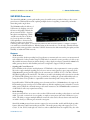
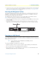
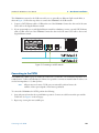
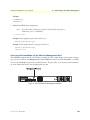
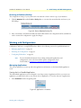
The SN10100 is connected to the VoIP network by one or optionally two Ethernet GigE network links, as
shown in Figure 5. Follow the steps below to connect the SN10100 to the VoIP network.
1. Connect a CAT5 Ethernet cable to VoIP0 at the rear of the SN10100. Connect the other end of the same
CAT5 cable to the Gigabit Ethernet switch.
2. If your system employs a second Gigabit Ethernet switch for redundancy, connect a second CAT5 Ethernet
cable to VoIP1 at the rear of the SN10100. Connect the other end of the same CAT5 cable to the second
Gigabit Ethernet switch.
Figure 5. Connecting to a VoIP network
Connecting to the PSTN
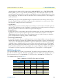
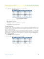
A SN10100 with 8 RJ48C type ports enables the connection to T1/E1 lines. The termination impedance is set
at 100 ohms for T1 lines and 120 ohms for E1 lines. It is possible to connect an external balun in order to convert the line impedance to 75 ohms (J1 line).
Note
All ports may not be active. T1/E1 ports are activated by software license; the
number of active ports depends on the licenses purchased.
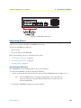
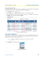
To connect the SN10100 to the PSTN, perform the following:
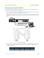
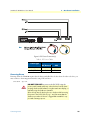
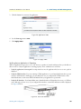
1. Start with port 0, located at the top and leftmost position. Connect one cable between this port and the
T1/E1 line. See Figure 6 on the next page.
2. Repeat step 1, using the next available port.
Connecting to the PSTN
22