1
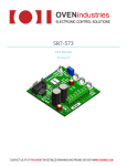
OVENindustries ELECTRONIC CONTROL SOLUTIONS 5R6‐900 USERMANUAL RevisionB CONTACT US AT 877-766-OVEN FOR DETAILED DRAWINGS AND PRICING OR VISIT WWW.OVENIND.COM TableofContents TABLE OF FIGURES .................................................................................................................................................................. 2 MANUAL OVERVIEW ............................................................................................................................................................... 3 BRIEF OVERVIEW ................................................................................................................................................................. 3 WHO SHOULD READ THIS MANUAL .................................................................................................................................... 3 TECHNICAL SUPPORT .......................................................................................................................................................... 3 SUPPLEMENTAL INFORMATION .......................................................................................................................................... 3 PACKAGE CHECKLIST ............................................................................................................................................................... 4 GENERAL DESCRIPTION ........................................................................................................................................................... 5 FEATURES & SPECIFICATIONS ............................................................................................................................................. 5 UNIT INTERFACE ...................................................................................................................................................................... 6 FRONT OF THE UNIT ............................................................................................................................................................ 6 BACK OF THE UNIT .............................................................................................................................................................. 7 GUI AT A GLANCE .................................................................................................................................................................... 8 PC Communications ........................................................................................................................................................ 9 General Output ............................................................................................................................................................... 9 Tuning ........................................................................................................................................................................... 10 Calibration ..................................................................................................................................................................... 10 Sensor Types ................................................................................................................................................................. 11 Configure ....................................................................................................................................................................... 12 Ramp and Soak .............................................................................................................................................................. 13 Sampling ........................................................................................................................................................................ 14 Download Defaults ........................................................................................................................................................ 14 Unit Alarms ................................................................................................................................................................... 15 Datalog .......................................................................................................................................................................... 15 SET UP INSTRUCTIONS .......................................................................................................................................................... 17 PREFLIGHT CHECKLIST ....................................................................................................................................................... 18 APPENDIX .............................................................................................................................................................................. 19 A. TROUBLE SHOOTING THE COMMUNICATIONS PORT ............................................................................................... 19 B. 5 MINUTES TO P.I.D. ................................................................................................................................................. 20 C. SENSOR TYPES AND RECOMMENDED TEMPERATURE RANGES ................................................................................ 22 1 TABLEOFFIGURES Figure 1 ................................................................................................................................................................................... 6 Figure 2 ................................................................................................................................................................................... 7 Figure 3 ................................................................................................................................................................................... 8 Figure 4 ................................................................................................................................................................................... 9 Figure 5 ................................................................................................................................................................................... 9 Figure 6 ................................................................................................................................................................................. 10 Figure 7 ................................................................................................................................................................................. 10 Figure 8 ................................................................................................................................................................................. 11 Figure 9 ................................................................................................................................................................................. 12 Figure 10 ............................................................................................................................................................................... 13 Figure 11 ............................................................................................................................................................................... 13 Figure 12 ............................................................................................................................................................................... 14 Figure 13 ............................................................................................................................................................................... 14 Figure 14 ............................................................................................................................................................................... 15 Figure 15 ............................................................................................................................................................................... 15 2 MANUALOVERVIEW BRIEFOVERVIEW The 5R6‐900 user manual describes the processes involved in the installation, and configuration of the product, as well as the standard methods of operation. It is advised that users familiarize themselves with the information detailed in this manual before operating the unit in order to ensure user safety. WHOSHOULDREADTHISMANUAL This manual contains important information anyone involved in the installation, maintenance, or operation of the 5R6‐900. TECHNICALSUPPORT Our technical support team comprised of knowledgeable engineers who are always willing to answer any questions you may have about our products. We can be reached both by telephone (during standard business hours) and through our website. If you have any other questions in regard to possible custom applications or specific needs for a product, we are more than willing to help you find the perfect temperature control solution. By Telephone: 877‐766‐6836 (Monday‐Friday, 8:00 am‐5:00 pm EST.) On the Web: www.ovenind.com SUPPLEMENTALINFORMATION Data sheets and customer drawings are always available for reference to our customers. We can also provide software updates, .DLL files, and other important information. If there is any other information you require, our technical support team is always ready to assist you with whatever you might need. Additionally, information can be downloaded from our website. 3 PACKAGECHECKLIST After receiving the 5R6‐900, please check for the following: Make sure the package includes the following items: 1. 5R6‐900 bench top controller 2. Power cord 3. CD with GUI communication software and digital version of the user manual 1 2 3 Once you have made sure that all the materials are present, inspect the unit to make sure it was no damaged during shipment. 4 GENERALDESCRIPTION The 5R6‐900 is a bi‐directional thermoelectric controller with a full solid state MOSFET H‐Bridge that can be applied to a broad spectrum of applications that require precision temperature control. The flexible design allows users to configure the unit to just heat, just cool, or seamlessly transition between the two instantaneously. The 5R6‐900 can be inserted into existing 120/240 volt systems with no adjustment. It can monitor both a primary control sensor and an optional secondary sensor that can be used for alarms. Capable of loads up to 10 Amps, the 5R6‐ 900 desktop unit also includes an isolated RS232 communications port, and is fully programmable via PC. The unit also contains a pair of DC point to point connections that can be used to drive any 24 volt auxiliary device the system might require, such as fans, pumps, solenoids or peltiers. The 5R6‐900 can be tuned in either Celsius or Fahrenheit, and the temperature resolution for either setting is 0.01°. This allows the unit to provide control stability up to ±0.01° in a well designed thermal system. FEATURES&SPECIFICATIONS AC Input: 85 to 260 VAC; Fused at 6.3A Temperature resolution: 0.01°C Set point resolution: 0.01°C PID Functions: Bandwidth : 0.1 to 50°C Integral: 0 to 10 repeats per minute Derivative: 0 to 10 minutes Ambient Temperature range: -20 to 50°C AC/DC Power isolation: 1500VAC Bidirectional load rating: 2.0 to 20VDC/10A Auxiliary DC Output (Fan Control) RoHS Compliant Compact size Thermistor and RTD sensor input 10 AMP load current capable Heat, Cool or H-Bridge operating modes PID control, parameters set via GUI Front Panel Mounted Display Auto output shutdown if sensor is open or shorted Optional high and low alarm settings via GUI Isolated RS232 communication port 5 UNITINTERFACE FRONTOFTHEUNIT The front of the unit consists of an easy to use menu display that allows the user to change the basic functions of the thermal system with just a few button presses. 5 1 4 3 2 Figure 1 Key: 1. Power Switch: This switch turns the unit on and off. 2. Display: This 2 x 16 character LCD display is used to give users important information about the current settings of the unit at a glance. 3. Menu Button: This button will allow the user to toggle between the different menu options below is the list for the cycle of the menu screens. a. Main Menu: The default display for the unit, this gives the current temperature, as well as the desired set temperature. b. Set Temperature: This allows the unit’s set temperature to be changed through the up and down arrows on the front of the unit. c. Set Voltage: Adjusts the maximum voltage for the H‐Bridge to change the pulse width modulation of the unit. d. Output Enable: This menu allows the user to toggle the power to the output on and off. 4. Up Navigation Button: This button allows the user to scroll through options on the selected menu. 5. Down Navigation Button: This button allows the user to scroll through options on the selected menu. 6 BACKOFTHEUNIT The back of the 5R6‐900 is where all the connections are made to both the PC and the thermal system. Below is a detailed outline of what each connection does. 14 13 1 3 2 5 4 8 6 11 9 7 10 12 Figure 2 Key: 1. 2. 3. 4. 5. 6. 7. 8. 9. 10. 11. 12. 13. 14. H‐Bridge (Heat‐/Cool+): This is the output for the primary load the 5R6‐900 will be controlling. H‐Bridge (Heat+/Cool ‐): This is the output for the primary load the 5R6‐900 will be controlling. Spare Wire Connection: This connection is not used at this time. Spare Wire Connection: This connection is not used at this time. Temperature Sensor Alarm: This is for the connection to the unit’s alarm sensor. Temperature Sensor Alarm: This is for the connection to the unit’s alarm sensor. Temperature Sensor Control: This is for the connection to the unit’s primary sensor. Temperature Sensor Control: This is for the connection to the unit’s primary sensor. Spare Wire Connection: This connection is not used at this time. Circuit Ground Connection: This is the connection to ground for the unit. FAN (Open Drain): This connection is the ground for the auxiliary 24 volt DC devices. Fan 24V+: This connection is the positive power for the auxiliary 24 volt DC devices. AC Power: This is the unit’s connection to a 120 or 240 volt line through the use of the included power cord. RS232 Communication: A 9 pin sub D connection for connecting a PC to the controller for setup. 7 GUIATAGLANCE Before the 5R6‐900 can begin to monitor and stabilize a thermal system, it must be set up to match the user’s specific temperature needs. Below is an image of the entire GUI, followed by a description of each section and its functions. Figure 3 8 PCCommunications The PC communication is the most important thing to note when first opening the PC program. After the unit has been connected to a computer, this section allows the user to select the comm port that will be used for communication between the computer and the unit. To set up the comm port, first determine which port the connection is on in the windows device manager. Select Ports (COM & LPT) from the menu to locate your specific port number. Select this comm. number from the drop down menu and hit the CommCheck button. If the Display reads “COMM OK”, then you are ready to proceed. Once the proper comm. port is Figure 4 selected, simply hit initialize to begin communication between the PC and the unit. Note: In the event any other message appears, refer to appendix 1 for troubleshooting assistance. GeneralOutput The general output section is a short listing of the basic information the controller is currently monitoring. Figure 5 Temp1: The current temperature of the control sensor. Voltage: This is the current voltage output of the system. Output %: The current percentage of power being applied to the system. Temp2: The current temperature of the alarm sensor (if applicable). Set: The current set temperature of the system. Log Enable: These check boxes denote which values will be stored and recorded in the Datalog output Note: In order to have these numbers displayed, the unit must be currently sampling (See Sampling on page 14). 9 Tuning The tuning section allows the user to set the set of variables that hold the system within the bounds of the desired temperature. Figure 6 Fixed Set Temp: This is where the desired set temperature is set for the unit. Note that this temperature will override any settings set on the display. Proportional Bandwidth: This displays the current bandwidth the proportional gain will apply power between. Integral Gain: Sets the current gain for the integral value. Derivative Gain: Sets the current gain for the derivative value. Set Switch Voltage: This value sets the output voltage from the switch. Alarm Setting: This setting is to specify the temperature value for the alarm sensor. LCD View: This value will modify the contrast of the LCD screen on the unit. Note: For more information on PID, refer to appendix B Calibration The calibration settings allow the user to fine tune a sensor; this is done by ensuring the sensor is working at optimal performance. Since every sensor can vary slightly, these settings allow the user to modify the input to make sure the readings are as accurate as possible. Input1 offset: Sets the offset for the primary sensor of the system. Input2 offset: Sets the offset for sensor2 of the system. Figure 7 10 SensorTypes These numbers represent the polynomials for specific thermistor curves. This allows the user to adjust the unit to match any desired thermistor curve. These values have programmed into the unit by simply selecting the specific Oven Industries sensor using the drop down menu. Note: A list of the general specifications for each family of sensor is located on page 22. Figure 8 The Thermistor Curve Equation: T=1.0/(A+(B*log(R))+(C*log(R)^2)+(D*log(R)^3))‐E Using this equation, it is possible to fine tune the system around a specific sensor. This calibration is automatically calculated by the unit based on the coefficients and the series of the sensor that is specified in the Sensor Types box. Note: In the event that the sensors in the sensor type list do not match the specifications required for a project, any thermistor curve can be added to the list by simply contacting Oven Industries. 11 Configure The configuration settings allow the user to manipulate the type of control the unit does, as well as set alarms for the sensors. Figure 9 Heat/Cool: This setting determines whether the controller will be used to heat, cool or if the H‐Bridge will control the temperature settings of the unit. Alarm: If an alarm sensor is being used, this setting allows the user to select if they would like the alarm to be above, or below the set temperature, as well as determine which sensor to use for the alarm being set. Heat Side multiplier: A number between 0 and 1 that represents the maximum allowable power output for a heating element. Setting this number to 0 prevents the unit from being able to heat the system. (0.5=50% power). Cool Side multiplier: A number between 0 and 1 that represents the maximum allowable power output for a cooling element. Setting this number to 0 prevents the unit from being able to cool the system. (0.5=50% power). SET TYPE: This setting comes with three distinct values for using the primary sensor. FIXED SET: SET FROM THE UNIT DISPLAY DIFF. SET (FIXED_SET+TEMP2): THIS ALLOWS THE UNIT TO USE DIFFERENTIAL CONTROL RAMP AND SOAK: THESE ALLOW THE CONTROLLER TO UTILIZE THE RAMP AND SOAK CONTROL FUNCTIONS Control Sensor Type: This option has two settings: Resistive and Voltage. The resistive setting is for utilization of the standard RTD and thermistor sensors. The voltage setting allows the user to linearly map the voltage between 0 volts and 5 volts. Alarm Sensor Type: This option has two settings: Resistive and Voltage. The resistive setting is for utilization of the standard RTD and thermistor sensors. The voltage setting allows the user to linearly map the voltage between 0 volts and 5 volts. 5V Sensor MAP: This setting allows the user to select the high side of the linear mapping for the specified temperature. 0V Sensor MAP: This setting allows the user to select the low side of the linear mapping for the specified temperature. Example: After selecting the Control Sensor to the Voltage setting, 50.00 is put into the 0V sensor map and 100.00 is put into the 5V sensor map. 2.5 volts is now mapped to 75.00°C (since the mapping follows a linear curve from the low end to the high end). 12 RampandSoak The ramp and Soak option is used for setting specific temperature profiles for set periods of time. Up to sixteen individual profiles can be set. Figure 10 RAMP/SOAK START: This starts the ramp and soak program, based on the settings specified. RAMP/SOAK ABORT: This cancels the ramp and soak process; if it is currently being run. RAMP/SOAK SETUP: This button brings up a menu to set the parameters for the ramp and soak process for a user’s specific application. RampandSoakSetup RS SEGMENT: These are the segments used to create each profile for the ramp and soak function. Soak Temp: This is the temperature that is the desired soaking temp. Soak Time: This is the amount of time the unit will remain at the current soak temp before moving on Ramp Time: This time determines how long it will take for the system to go from the current temperature to the soaking temperature Repeat Count: This setting controls the number of times the unit will repeat a given pattern of temperatures. Figure 11 Repeat Location: Once the profile is complete, if a Repeat count is specified, the unit will go to this segment of the profile and follow it. 13 SOAK TIMER METHOD: This selection gives the option of choosing how the profile will end. SET TEMP ONLY: Once the time specified has been transpired, the profile changes. Even if the set temperature has not been reached. CONTROL TEMP: Delay profile until the set temperature has been reached. SOAK TRACKING TEMP: This is the number of degrees (bandwidth) of acceptable range for the temp to be able to move on. RAMP/SOAK INCREMENT COUNTER: Used to adjust the resolution of the ramp soak timer. This is a number between 1 and 32000. This number is multiplied by .011 and that is the length of each sample interval. Sampling This function allows you to increase (or decrease) the sample time while the computer is connected to the unit. Note: This has no effect on the unit’s actual sample time; it is merely for displayed reference. Figure 12 DownloadDefaults A password is required to access some of the more delicate settings of the controller. This password is provided at the time of purchase. The over current setting is a protection circuit that monitors the voltage and current of the system to protect it from current overdraw and inadequate voltage to drive the system. This setting can be modified, but it is recommended that the user consult with Oven Industries engineering department Figure 13 before doing so. In case of either event, the power supply and the voltage at the input terminals should be checked. The trip limit may also need to be adjusted before the system is ready to use again. The download defaults button allows the user to wipe all the settings from the computer and reset them back to the factory default settings. Warning: All previous data saved to the unit will be lost after restoring the unit to default settings! 14 UnitAlarms Output Enable: In the event of an alarm, this check box allows the user to immediately shut off the power to the load. Over Current Detect: This alarm will blink if the unit detects any overdraw of current. Sensor 1 Error Status: Any error with the sensor will cause this alarm to trigger; this could be anything from not being properly connected to a short. Sensor 2 Error Status: Any error with the sensor will cause this alarm to trigger; this could be anything from not being properly connected to a short. Control Board Over Temp: This alarm setting is hardcoded into the unit; in the event that the temperature of the board exceeds this limit, the unit will shut off automatically? Alarm Status: A general alert that there is an issue with the board. All other alarms trigger this one as well. Figure 14 Datalog The datalog function allows the user to keep track of the current temperature, set temperature, and output percent for each sample. Once these numbers have been logged, they can be easily copied and pasted into a spreadsheet for further analysis. Figure 15 15 TheGraph Figure 16 Included with the GUI for the 5R6‐900 is an eight minute rolling differential graph. This allows the user to observe the previous progress of the thermal system for analysis, or modification of the current settings to create the most accurate thermal system possible. The y axis of the graph represents the difference between the set temperature and the actual temperature (in degrees), while the x axis is broken down into sixty second increments. The Redraw Button will completely clear the graph, allowing only new data to be displayed. 16 SETUPINSTRUCTIONS This guide has been provided to get the 5R6‐900 set up and running as fast as possible. Please read the entire instruction set and ensure you are familiar with it before beginning setup. Not following these instructions may result in the unit not being able to properly maintain the temperature of the thermal system. 1. AC Power: Without a load (heater or TEC) connected to the unit, connect the 5R6‐900 to AC power using the AC line cord. Turn on the controller using the power switch on the front panel. NOTE: The unit should display the current software revision on start up. 2. Attach the Communications Cable: Connect a communications cable from the controller to your PC (see page 5). The connector required for the back of the controller is a standard DB9 (DE9P) connector. 3. Launch the Setup Software: Note the execute command shown on the label of the software disk. Insert the disk into the PC and use this command to launch your controller’s Setup program. This will allow you to access the GUI (See Figure 3). 4. Select the Communications Port: In the PC COMMUNICATIONS section of the GUI, select the Communications Port and click the COMM CHECK button. The GUI should then display COMM OK. If any other message is displayed. The communication has failed. If the software fails to communicate with the unit, see Appendix A, “Troubleshooting the Communications Port”. If you need to Exit the program you can use the Closer (the “X” button, top right) to exit, and then return to step 3. Once communication has been established, click the INITIALIZE button. Within a couple of seconds you should see values in the TUNING, CALIBRATE, and CONFIGURE sections. 5. Set the Thermistor Constants: Click the Sensor Type button and select the type of sensor being used for the application. 6. Set the Alarm: While in an alarm state, the output power to the load will be turned off. Use this feature as a precaution against excessively high temperatures: In the CONFIGURE section set the ALARM to High Alarm and click the section’s Send Box Values button, and then in the TUNING section enter the high temperature value as the ALARM SETTING and click the section’s Send Box Values button. Or, in a similar way, you can choose to use a Low Alarm, or you can choose to disable the alarm feature. Choose to disable the alarm if you are using only a control sensor and no alarm sensor. By default, the GUI is set to no alarm. 7. Select the Heat/Cool Mode: In the CONFIGURE section select the appropriate HEAT/COOL multipliers for your application. If using only heating or cooling, set the multiplier not being used to 0. Once you are finished click Send Box Values. 8. The Set Point Temperature: In the TUNING section enter the desired set point temperature as the FIXED SET TEMP and click Send Box Values. The temperature scale is Celsius (°C). This number can be later adjusted using the keypad on the unit itself. NOTE: Ambient room temperature of 70°F is about 25°C. If you want to gain experience with the controller near ambient start with 25 as the FIXED SET TEMP. 9. Tune the PID Control: In the TUNING section use the PROPORTIONAL BANDWIDTH (P), INTEGRAL GAIN (I), and DERIVATIVE GAIN (D) to tune the PID control. You can start with 10 for the bandwidth, and 0 (zero) for the integral and derivative gain. Enter your PID values and click Send Box Values. Once you are familiar with the operation of the unit, you can use Appendix D, “5 Minutes to PID Tuning of the Temperature Controller” to fine tune your thermal system to pinpoint accuracy. 17 10. Exit the Setup Program and then Turn Off the Controller: Use the File menu and Exit to exit the program, and use the power switch at the back of the controller to turn off the controller. 11. Connect the Load: Connect your load (heater or TE module) to the LOAD+ and LOAD‐ on the back of the unit. (See page 7 for details on the specifics of where to plug these wires into). 12. Attach the Sensors: Place the control sensor into the heater or TE module thermal system at the desired control point. Connect the sensor to the back of the unit. Do the same for the alarm sensor if you are using one. 13. Check all connections. 14. Turn the Controller On and it will Immediately Begin Controlling the Temperature: The control sensor’s temperature will be indicated on the front panel display. By cycling the display using the front panel’s DISPLAY SELECT button, and noting the LED indicators, you can view the actual and set temperatures, as well as the set voltage. By using the INCREASE and DECREASE buttons, you can adjust these settings from the unit. 15. Launch the Setup Software: If you want to use the setup program to change controller parameters or log data, launch the program according to the instructions for steps 3 and 4. If you want to datalog, click the Box Enable checkbox below the Datalog box, as well as the Log Enable check boxes next to the General Output boxes and hit the sample button. 16. Setup is Complete: It is a good idea to use safe temperature settings in order to become accustomed to your set up and to tuning the controller. PREFLIGHTCHECKLIST Did you… Select a TEM to match the voltage and current rating of the unit? Connect the temperature probe to the controller? Connect TEM connections to the controller? Connect the serial interface cable? Connect power to the controller? Select a serial port on your computer? Initialize the GUI (graphic user interface) with the controller? Select the appropriate sensor from the GUI listbox? Check for a valid temperature via sample function? Choose a temperature setpoint? (start with default tuning parameters) Enable output to be on? Send new settings to the controller? 18 APPENDIX A. TROUBLESHOOTINGTHECOMMUNICATIONSPORT This section can be used as a guide to navigate the most common errors encountered while making connections to the communications port. ERRORMESSAGE CAUSE SOLUTION Comm Port Timeout No power to temperature control unit Supply power to the unit Comm Port Timeout Wrong comm port selected Comm Port Timeout Incorrect wiring of the comm port to the computer Check computer hardware settings and set to the correct comm port Check for the correct wiring from the comm port to the computer Comm Port Open Error No comm. port available at this port setting 19 Check computer hardware settings and set to the correct comm port B. 5MINUTESTOP.I.D. Tuning the TE temperature controller involves three variables. (P)ropotional bandwidth, (I)ntegral action, and (D)erivative rate. The control algorithm sums the three values of these terms to determine the output power. P + I + D = % Power Applied Most applications work satisfactorily with only the “P” and “I” values used. Start the tuning process by setting the Integral and Derivative functions to zero. Proportional Bandwidth is defined as the temperature range around the set‐point where the controller modulates (proportions) the output power. In a heating application, if the temperature is above the proportional band, the controller output is OFF. If the temperature is below the proportional band, the controller output is ON. Each thermal system has its own time constants determined by the thermal mass of the components and the placement of the sensor relative to the load. To tune the system the bandwidth must be wide enough that the controller can sense a change and react to it before the temperature drifts outside the bandwidth. If the band‐ width is too small the output will oscillate above and below the set‐point, never settling into control. The bandwidth range is 1° to 100°. The units are shipped with a default setting of 20°. Assuming the controller is configured for your requirements, start the tuning process by applying power with the default settings and observing the system’s response. If the system comes into the proportional band and maintains a steady temperature near set‐point, without over shoot, the bandwidth setting is satisfactory or too large. Reduce the bandwidth setting until the system just begins to oscillate. At this point, the bandwidth is too small. Note the bandwidth setting that just caused the system to oscillate, record the period of oscillation for use in determining the Integral Reset setting. To set the proportional bandwidth, multiply the current bandwidth setting by 1.5 and use it as your new bandwidth setting. The system should come into control and maintain a steady temperature near the set‐point. Integral Reset monitors the difference between the set point and the actual temperature. Its function is to slowly change the output power until the delta between actual temperature and set temperature is zero. The function works by integrating the error signal at fixed intervals. These intervals are expressed in repeats/minute. The acceptable range is 0.01 to 10 repeats /minute. Start with a setting determined by the following formula. Integral Reset = 1/P x 1/2 Note: Period is expressed in minutes. 20 Example: Thesystem‘speriodofoscillationwithnarrowbandwidthwas75seconds.Therefore thesuggestedIntegralRateis: IntegralReset=1/1.25min.X1/2 IntegralReset=0.4repeats/minute Forslowerresponsereducethenumberofrepeatsperminute. NOTE: DERIVATIVE RATE IS DIFFICULT TO APPLY. IF YOU ARE NOT EXPERIENCED IN PROCESS CONTROL, ASK FOR HELP NOW! Derivative Rate senses the rate of change of the temperature and allows the controller to anticipate power needed to compensate for rapid changes in system loading. This term is generally used only on very sluggish systems or where very quick response is necessary. The acceptable range is 0.01 to 10 cycles/ minute. To determine an appropriate derivative rate, use the following formula. Derivative Rate = Integral Reset / 10 For the example above the Derivative Rate would be .06 cycles per minute. The Derivative function is difficult to use and often causes more trouble than it is worth! Our technical support team is always available to help guide you through this process. 21 C.SENSORTYPESANDRECOMMENDEDTEMPERATURERANGES This sensor chart will help guide you to selecting a sensor that best fits your application. All Oven Industries sensors come in wide variety of optional sheaths and can be either leaded and RoHS compliant. Oven Industries Sensors: SensorFamily Tolerance TemperatureRange BaseResistance(@25°C) TR67 ±1.0°C (0°C to 100°C) ‐20° to 110°C 15KΩ TR91 ±1.0°C (0°C to 100°C) ‐40° to 150°C 10KΩ TR104 ±1.0°C (0°C to 100°C) 0° to 150°C 50KΩ TR136 ±0.1°C (0°C to 70°C) ‐20° to 110°C 15KΩ TR141 ±1.0°C (‐40° to 70°C) ‐40° to 90°C 5KΩ TR165 ±1.0°C (0°C to 200°C) 25°C to 250°C 230KΩ Other General Sensors: SensorFamily TemperatureRange BaseResistance(@0°C) PT100 ‐200° to 850°C 100Ω PT1000 ‐200° to 850°C 1KΩ 22