1
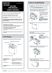
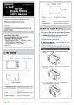
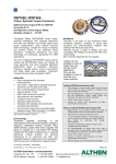
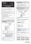
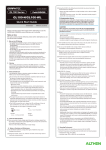
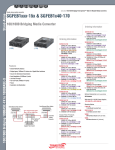
GL7-DCB-UM-151
GL7-DCB
GL7000
Strain Module
USER’S MANUAL
2 How to Install Module
This explains how to attach the module to the main module.
When installing or removing the module, please
make sure that the power is off.
1, Remove the fixation screws (4 places on the upper part and
lower parts), place the alarm module parallel to the main
module and slide it in the direction of the arrow.
(1) Remove the fixation screws from
the 2 places on the lower part.
3
Thank you very much for buying this GRAPHTEC product.
This item is a standalone measuring module. Please use it by
These directions describe preparations and cautions before
measurement.
For safe use, please make sure to read “4 Regarding
Maximum Input Voltage”
For the details concerning operation procedures etc., read
the User’s manual recorded on the CD-ROM (included with
the main module)
You can use in GL7000 firmware (V1.20) and GL-Connection(V1.20)
or later.
(2) Loosen the drop-off prevention
screws on the upper part in 2
places.
4
2
(3) Removing the alarm module.
1
Slide it in the direction of the
arrow. If you pry it at an angle
there is a risk of damaging the
connector.
Alarm module
2, Remove the strain module's fixation screws
(2 places on the lower part).
Confirmation of the exterior
After opening the package, please confirm that there are no
problems (scratches and dirt) on the exterior before use.
1
2
Confirmation of the attached items.
DSUB (male) connector
If by any chance faults are found, please contact the store where you
bought the item.
3, Slide the strain module parallel to the main module and
connect the connector.
* Please note that items mentioned in this book may change without prior notice.
Connector
Slide it in the direction of the
arrow.
Inserting it at an angle may cause
damage to the nails.
1 Part Names
Explanation of the module's part names and functions.
1, Module connector
Nail
2, Module fixation screw (Upper part)
3, Power LED
4, Fix the strain module and the main module in place with the
screws. (4 places on the upper and lower parts)
7, Auto-balancing switch
1
2
5, Strain, voltage,
resistance input terminal
4
3
6, DIP switch
4, Module fixation screw (Lower part)
1, Module connector.............. Connector for connecting all kinds of modules.
2, Module fixation screw....... Fixation screw for the adjoining module.
To prevent drop off, do not remove from
(Upper part)
the module.
3, Power LED.......................... The Power LED will light up green when
the power has been turned on and the
module has been recognized.
However, this LED flashes during auto-balancing.
4, Module fixation screw....... Fixation screw for the adjoining module.
(Lower part)
5, Strain, voltage,
resistance input terminal.. Terminal for inputting analog measurements.
6, DIP switch........................... This is used to switch to strain, voltage or
resistance.
7, Auto-balancing switch....... This is used to set the initial value of the
strain to 0 (zero).
5, Similarly, install the alarm module on the last part and fix it with
screws.
1
2
4
3
During installation, a
Das empfohlene
Schrauben4kgf.cm
screw tightening
Anzugsdrehmoment
beträgt:
torque
is recommended.
0,39 Nm.
Frankfurter Strasse 150-152 | 65779 Kelkheim | +49 (0)6195 70060 | www.althen.de | [email protected]
3 How to Connect to Analog Signal Terminal
This section describes the signal input terminal and how to set the DIP switch.
1. Input terminal arrangement and descriptions
Strain, voltage,
resistance input
terminal
(Soldering side)
(5)(4)(3)(2)(1)
DSUB
(male)
When connecting the
connector,
please be careful not to
over-tighten the screw.
Recommended tightening torque
: 4 kgf·cm or less
(9)(8)(7)(6)
DSUB
Connector No. Notation
(1)
B(2)
IN(3)
S+
(4)
T(5)
R+
(6)
S(7)
IN+
(8)
B+
(9)
T+
Connector
chassis
Descriptions
Excitation voltage (-)
Input signal (-)
Sense (+)
TEDS (-)
Shunt resistance
Sense(-)
Input signal (+)
Excitation voltage (+)
TEDS(+)
Shield
Options
A
E
C D
In case the measured values fluctuate due to exogenous
noise, the following measures are recommended.
(Depending on the type of noise, the result may change.)
Make absolutely sure to ground the chassis GND
of the measuring object
Absolutely making sure to ground the chassis GND of the
measuring object to a favorable ground may have an effect.
Connecting the chassis GNDs of the measuring
object and the instrument
Connecting the chassis GND of the measuring object and
the GND terminal of the main module with an electrical
cable as short and thick as possible, and further gaining
potential equalization by grounding it may have an effect.
Equipment to
be measured
GL7000
GND terminal
FG
Conversion connector
between DSUB
and screw terminal
(B-560)
F
G E
B
DIP switch
DSUB-NDIS Conversion connector between
Conversion cable DSUB and screw terminal
C
1
B
2
3
G
4
5
6
D
7
A
8
F
9
5 Noise Countermeasures
GND terminal
Grounding
Using the filter function of the instrument
Setting the filter to anything but OFF on the main body's
input settings menu.
Conversion cable between DSUB and NDIS
(B-561) NDIS Pin (female)
For details, please refer to the User’s manual recorded on the CD-ROM (included with the main module)
2. Depending on the input method, set the switch (See Table below).
Table below shows the settings of DIP switch.
For the numbers in the table, 0 (zero) is OFF and 1 is ON.
Input method
Strain
input
2-wire 1/4bridge
3-wire 1/4bridge
4-wire 1/4bridge
3-wire 1/2bridge
4-wire 1/2bridge
5-wire 1/2bridge
4-wire full bridge
6-wire full bridge
Strain sensor input 4-wire
6-wire
Voltage input/Resistance input
1
1
1
1
0
0
0
0
0
0
0
0
2
1
1
1
1
1
1
0
0
0
0
0
3
1
0
0
0
0
1
0
1
0
1
0
4
1
0
0
1
1
1
1
1
1
1
1
5
1
1
1
1
0
0
1
0
1
0
1
6
1
1
1
1
1
1
1
1
1
1
1
7
1
1
1
1
1
1
1
1
1
1
1
1
1
1
1
0
0
0
2
1
1
1
1
1
1
3
1
0
0
0
0
1
4
1
0
0
1
1
1
5
1
1
1
1
0
0
6
0
0
0
0
0
0
6 Specifications
7
0
0
0
0
0
0
Set the DIP switch as
shown in the left table
* Voltage and resistance
inputs do not affect the
strain gauge.
GL7-DCB (Strain Module) specifications
Item
Input ch number
Input terminal shape
Input system
Sampling interval
Built-in RAM
Input type
Measurement
Strain
range
This explains how to connect the input cable.
Voltage
Resistance
During wiring, confirm that the signal's supply source
is turned OFF to prevent electrical shocks.
Strain input
1. When connecting the strain sensor (acceleration, load cell, etc.)
Connect with either the DSUB (male) Connector supplied as standard or the
optional DSUB-Screw terminals conversion cable (B-560).
(For the settings of DIP switch, refer to the table above.)
2. When connecting the strain gauge (Figure below shows an example of
use the supplied DSUB (male)
connector to connect (2) and (8) terminals.
2-wire 1/4bridge (120
gauge)
(Set the DIP switch as
shown in the right figure.)
(8)B+
(2)IN-
Voltage and resistance inputs
1. Voltage input
2. Resistance input
Use the supplied DSUB (male) connector
When measuring the resistance, as
to connect to (2) and (7) terminals.
shown in Figure below, wire using
the following 4-wire, or short
(7)IN+ IN+...High potential terminal
Direct
voltage
between (1) and (2) , and (7) and (8).
(2)IN- IN-...Low potential terminal
(Set the DIP switch as
shown in the right figure.)
ON
1 2 3 4 5 6 7
(7)IN+
(8)B+
(2)IN(1)B-
4 Regarding Maximum Input Voltage
To avoid break-downs or short-circuiting accidents, please
make sure to abide by the items written below.
Maximum input voltage
In case the input voltage exceeds the specifications, the circuit at the
input part will break down. Please don't input it.
<Input terminal (+)/ Input terminal (-) interval>
Maximum input voltage
<Input terminal (-)/Input terminal (-) interval>
<Input terminal (-)/GND terminal interval>
Measurement
Strain
accuracy *1
Voltage
Resistance
Contents
4 ch/1 module
DSUB 9-pin (female)
All ch insulation, simultaneous sampling, balanced input
to1 hour
2,000,000 data
Strain, voltage, resistance values (including potentiometer)
400, 500, 800, 1000, 2000, 4000, 5000, 8000, 10000,
-6
(
10 Strain)
0.2, 0.25, 0.4, 0.5, 1, 2, 2.5, 4, 5, 10 mV/V
* The range depends on the bridge voltage.
1, 2, 5, 10, 20, 50, 100, 200, 500 mV, 1, 2, 5 V
1, 2, 5, 10, 20, 50, 100, 200, 500 ,
1, 2, 5, 10, 20, 50 k
(0.2% of F.S.
)
(0.2% of F.S.
)
*1 After power-on, more than 30 minutes, sampling 1 sec., filter line, GND
A/D converter
Gauge factor
Sensor
supported
(
2.0 constant
Strain [Strain gauge transducer]
4-wire full bridge, 6-wire full bridge (Available for remote sensing)
[Strain gauge]
Resistance Potentiometer, resistance
Internal gauge resistance 50 to
(Excitation voltage
to 10k , 5V/
Internal gauge
resistor
Excitation voltage
DC 1, 2, 2.5, 5, 10 V
to 10k ,
to 10k )
)
to 10k ,
Constant current
0.1 to 20 mA (Voltage supported
bridge power supply
Balancing
)*Strain input only
Remote Sensing
3 or 4-wire 1/4bridge, 4 or 5-wire 1/2bridge,
and 6-wire full bridge are available.
Shunt calibration
Internal approximate 60k (120 gauge), approximate 175k (350 gauge)
Temperature
coefficient
0 point
Input resistance
Maximum input
Differential input DC10V
voltage
Common-mode voltage 10VACrms
60Vp-p
Withstand voltage
1000Vp-p 1 minute
Insulation resistance
or more (at DC500 V)
Common mode rejection ratio
Noise
or less (DC2V
)
Frequency response DC to 20 kHz
Filter
L.P.F. OFF, Line (1.5 Hz) 3, 6, 10, 30, 50, 60 Hz,
100, 300, 500 Hz, 1, 3, 5, 10kHz at -30 dB/oct
A.A.F. OFF/ON (Anti-aliasing filter)
TEDS
External dimensions
49.2 × 136 × 160 mm (not including protruding parts)
[W×D×H] (approximate)
Weight (approximate) 840 g
GRAPHTEC Corporation April 1, 2013
Frankfurter Strasse 150-152 | 65779 Kelkheim | +49 (0)6195 70060 | www.althen.de | [email protected]