1
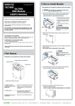
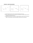
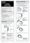
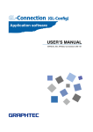
GL7-DISP-UM-151
8, Nail
9, Tilting table
10, Clamp
GL7-DISP
GL7000
Display Module
8, Nail
USER’S MANUAL
11, Mounting hole
8, Nail.................................... Nails for fixing to the main module
(4 places)
Thank you very much for buying this GRAPHTEC product.
This product is a display module for recording.
Please use it by installing it on the main module.
9, Tilting table
10, Clamp................................ Clamp for binding the monitor connection cable
11, Mounting hole.................. Threaded hole for fixing to the display module
These directions describe preparations and cautions before
measurement.
For the details concerning operation procedures etc., read
the User’s manual recorded on the CD-ROM (included with
the main module)
2 How to Install Module
This explains how to attach the module to the main module.
Confirmation of the exterior
After opening the package, please confirm that there are no
problems (scratches and dirt) on the exterior before use.
Confirmation of the attached items.
Instruction manual (this book): 1
Tilting table: 1 module
Monitor connection cable (40 cm): 1 pc.
Screws (M4x6): 3 pcs. Ground cable: 1 pc.
Flat Head Screws (M4x10) 2 pcs. (Spare)
If by any chance faults are found, please contact the store where you
bought the item.
* Please note that items mentioned in this book may change without prior notice.
When installing or removing the module, please
make sure that the power is off.
The display module has 3 basic positions.
A. When the main module is attached... fitting to the main module.
B. When using the tilting table... Use the tilting table (at a 15° tilt
angle) to fit to the main module.
C. When extending cables... Use a commercially available LAN cable,
and attach to a place separated from the display module on the main module.
A. This explains how to install when attaching the main module.
1, Remove fixation screws from the main module (2 places on
the side)
1 Part Names
Explanation of the module's part names and functions.
1, Monitor
2, Operation key
3, Threaded hole for mounting
1
2
2, Pull the nail on the upper-right side of the face cover, and remove
the face cover.
4, Connector for connecting to module
5, Threaded hole for mounting
6, Nail
Face cover nails
7, Monitor In connector
1, Monitor
3, Join the nails on the back of the display module with the inset
part of the main module, and push it in.
2, Operation key
3, Threaded hole for mounting... Threaded hole for fixing to the main module
4, Connector for connecting to module.. Connector for connecting to the main module
5, Threaded hole for mounting.. Threaded hole for fixing to the tilting table
(M4 Approx depth 5 mm)
6, Nail...................................... Threaded hole for fixing to the tilting table
(2 places)
7, Monitor In connector......... Connector for use when extending
cables, and when using the tilting table
Das empfohlene SchraubenAnzugsdrehmoment beträgt:
0,39 Nm.
Frankfurter Strasse 150-152 | 65779 Kelkheim | +49 (0)6195 70060 | www.althen.de | [email protected]
4, Join the display module with the module connector, and insert
into the main module.
5, Attach the fixation screws on the main module (2 places on the
side).
1
During installation, a
4kgf.cm screw
tightening torque is
recommended.
5, Attach the fixation screws of the main module (2 places on the
side).
2
6, Attach the ground cable to the main module (GND terminal)
with the fixation screws attached to the tilting table.
Tilting table
GND terminal
1
During installation, a
4kgf.cm screw
tightening torque is
recommended.
* If the ground cable is not connected,
sufficient performance may not be obtained.
2
C. This explains installation when extending cables.
(After the main module’s face cover is mounted)
B. This explains how to attach the tilting table for use.
(After the main module 's face cover is removed)
1, Connect the monitor out contact on the main module and the
monitor in contact on the display module with a commercially
available LAN cable.
Tilting table
Monitor connection cable
(40 cm)
Ground cable
1, Install by binding the monitor connection cable with the clamp
on the tilting table.
Bind so that the there is
approx. 25 cm between
the monitor connection
cable and the connector.
Please note the specifications of the LAN cable you use.
[LAN Cable specifications]
Type: Straight cable Category: CAT5 or above
Please use the display
module fixed to a board, etc.
2, Attach the display module to the tilting table with the attached
fixation screws (2 places).
1
2
Please do not connect a LAN cable
with the monitor in connector of
the display module and the LAN connector of the GL7000 main module.
During installation, a
4kgf.cm screw
tightening torque is
recommended.
3, Connect the connector of the monitor connection cable to the
monitor in connector of the display module.
3 Specifications
GL7-DISP (Display Module) Specifications
Item
Display device
Operating portion
touch-panel
4, Connect the monitor connection cable to the monitor out
connector of the main module and attach the 4 point nails on
the tilting table by fixing them to inset part of the main module
(4 places).
Cable length: 10 m or less
Display characters
Backlight
Backlight life
Display screen
Contents
5.7” TFT color liquid crystal display
(VGA: 640 x 480)
Capacitive touch-panel and key shared use
* Almost all operations can be performed by either the touch-panel or the keys.
Input method: Finger
Operating life: Approx. 50,000,000 times * It depends on the status of use, etc.
Japanese, English, French, German, Chinese, and Korean
Screen saver function (10, 30 sec.; 1, 2, 5, 10, 30, 60 min.)
50.000 hours (when brightness has decreased to 40%),
changes according to use environment
Waveform + digital screen, full waveform screen, digital +
operation screen, X-Y display
* CH number and display CH are designated for when the display of the
digital + operation screen is digitally enlarged
Monitor Out connector
Connection cable
LAN cable (straight, CAT5 and above, cable length 10 m or less)
(For cable extension) * Please purchase a commercially available product
Accessories
Tilting table 1 module Monitor connection cable (40 cm) 1 pc. Screws (M4x6) 3 pcs.
Flat Head Screws (M4x10) 2 pcs. (Spare) Groound cable 1 pc.
External dimensions
187 × 34.5 × 119 mm (Not including protruding parts)
[W×D×H] (approximate)
Weight
530g (Not including the tilting table)
Since the touch-panel in this module is a capacitive touch-panel, it does not
respond by touching it with a pen.
* Please note that if the touch-panel is operated with an object with a sharp edge, it
may scratch and damage the touch-panel.
* Do not touch when your hands are wet.
GRAPHTEC Corporation July 1, 2012
Frankfurter Strasse 150-152 | 65779 Kelkheim | +49 (0)6195 70060 | www.althen.de | [email protected]