1
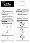
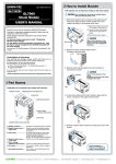
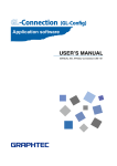
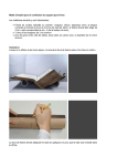
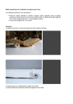
GL7-SSD-UM-151
GL7-SSD
GL7000
SSD Module
USER’S MANUAL
2 How to Install Module
This explains how to attach the module to the main module.
When installing or removing the module, please
make sure that the power is off.
1, Remove the fixation screws (4 places on the upper part and
lower parts), place the alarm module parallel to the main
module and slide it in the direction of the arrow.
(1) Remove the fixation screws from
the 2 places on the lower part.
3
Thank you very much for buying this GRAPHTEC product.
4
(2) Loosen the drop-off prevention
screws on the upper part in 2
places.
This product is a stand-alone module for recording.
Please use it by installing it on the main module.
2
These directions describe preparations and cautions before
measurement.
For the details concerning operation procedures etc., read
the User’s manual recorded on the CD-ROM (included with
the main module)
(3) Removing the alarm module.
1
Slide it in the direction of the
arrow. If you pry it at an angle
there is a risk of damaging the
connector.
Alarm module
2, Remove the SSD module's fixation screws (2 places on the
lower part).
Confirmation of the exterior
After opening the package, please confirm that there are no
problems (scratches and dirt) on the exterior before use.
1
Confirmation of the attached items.
User’s manual (this book): 1
2
If by any chance faults are found, please contact the store where you
bought the item.
* Please note that items mentioned in this book may change without
prior notice.
3, Slide the SSD module parallel to the main module and connect
the connector.
* SSD module must be connected to main module.
Connector
1 Part Names
Slide it in the direction of the
arrow.
Inserting it at an angle may cause
damage to the nails.
Explanation of the module's part names and functions.
2, Module fixation screw (Upper part)
Nail
1, Module connector
3, Access Lamp
4, Fix the SSD module and the main module in place with the
screws. (4 places on the upper and lower parts)
1
2
4
3
4, Module fixation screw (Lower part)
1, Module connector.............. Connector for connecting all kinds of modules.
2, Module fixation screw....... Fixation screw for the adjoining module.
To prevent drop off, do not remove from
(Upper part)
the module.
5, Remove the amplifier module's fixation screws.
(2 places on the lower part)
(Here, we explain using the Voltage Module as an example)
3, Access Lamp...................... During data access, it lights up green.
(Not lit, when normal operation)
* Please do not turn off the power when it's lit up.
1
4, Module fixation screw....... Fixation screw for the adjoining module.
(Lower part)
2
Das empfohlene SchraubenAnzugsdrehmoment beträgt:
0,39 Nm.
Frankfurter Strasse 150-152 | 65779 Kelkheim | +49 (0)6195 70060 | www.althen.de | [email protected]
6, Slide the amplifier module parallel to the main module main
module and connect the connector, and in the same way connect
the SSD module with the fixation screws. (4 places on the upper
and lower part)
Connector
3, When it returns to the File operations screen, choose “SSD
Module” to execute.
When a message like the one in the chart below is shown, select “Yes”.
Slide it in the direction of the
arrow.
Inserting it at an angle may cause
damage to the nails.
Nail
* The formatting process can take several minutes.
When using the application software GLConfig
1, After connecting between the module and PC using USB, turn
on the power of the module.
7, Similarly, install the alarm module on the last part and fix it with
screws.
1
2
4
(You must have installed the USB driver previously. For more information about
installing the USB driver, see the User’s manual of the USB driver included CD-ROM.)
2, Using “Start” on the Windows OS, select “All Programs” →
Graphtec → GL-Connection→ GLConfig to start the GLConfig.
(When using Windows 7)
3, Press "Load” button to connect to the module.
Select “SSD Module” in the items of the initialization, and then
press “Execute” button.
3
During installation, a
4kgf.cm screw tightening
torque is recommended.
3 Formats
For first time use, please format the SSD.
This explains the formatting procedures.
4, “Do you want to format?” message is displayed. Select <OK>.
“Initializing” message is displayed. When the formatting is
completed, the following screen is displayed.
(It may take a long time to format depending on the contents of the drive.)
* For details on operations, etc., please refer to the User’s manual recorded on the
CD-ROM (included with the main module main module)
When using the display module
1, Choose “File Operations” under “File” on the home screen.
4 Specifications
GL7-SSD (SSD Module) specifications
Item
SSD
Recording capacity
Sampling interval
2, When the File Operations screen is shown, select “Format”
from “Operations”.
Contents
2.5” SSD HDD (SATA I/F)
Approx. 64GB (However, 1 file can be up to 2GB in size)
* Depending on the amplifier in use, there may be limitations to the
sampling interval.
* The fastest amplification is limited to the amplifier in use.
* If a sampling interval that exceeds the fastest speed on each amplifier is set,
the sampling is set to each amplifiers’ fastest speed, and the same data is
recorded for that interval.
External dimensions 49.2 × 136 × 160 mm (not including protruding parts)
[W×D×H] (approximate)
Weight
770g
Vibration proof
Automobile parts Type 1 Class A equivalent
* Depending on the state of fragmentation of the SSD, there may be cases where the
sampling rate won't be written on time. (A message will be displayed during recording)
If this sort of event occurs, please backup important data to another media and format
the SSD.
GRAPHTEC Corporation July 1, 2012
Frankfurter Strasse 150-152 | 65779 Kelkheim | +49 (0)6195 70060 | www.althen.de | [email protected]