1
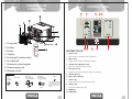
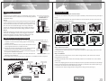
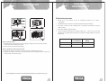
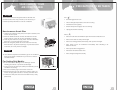
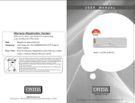
3 STAR
2 STAR
Warranty Registration System
Help us to serve you better by registering
your product for Warranty
- Web
Registered at www.onida.com
- Telephone
Call Centre No. 0XX-39889000(0XX-STD Code of
State Capital)
- Post / Visit
Post the Warranty Registration Card & Service Centre
Copy or Visit the Nearest Service Centre.
Model: W12TRC3 / W18TRC3
W12TRC2 / W18TRC2
AIR CONDITIONERS
The unit displayed is for representational purposes only. Actual unit may vary.
Dear customer
Congratulation on buying ONIDA Air Conditioner.
Your Air Conditioner comes with ONIDA Guarantee of Quality
as detailed in the manual.
ONIDA takes great pride in providing its customers with stateof-the-art products that adheres to international quality
standards.
ONIDA is committed to following quality policy laid by our
chairman and managing director Mr. G. L. Mirchandani.
“We are committed to quality and strive for continuous
improvement through innovation and human development to
give customer better value for money always”
ONIDA stands committed to provide the ultimate customer
satisfaction, as nothing brings us greater joy than having
satisfied customers of ONIDA.
At ONIDA, feedback and suggestions based on your product
usage experience is greatly appreciated.
Please contact to us at [email protected]
G. Sundar
Chief Executive Officer
IMPORTANT :
Please read this owner’s manual carefully and thoroughly
before installing and operating your room air conditioners.
Please retain this owner’s manual for future reference after
reading it thoroughly.
CONTENTS
Salient Features
1
Inside Air Conditioner
2
Control Panel
3
Remote Overview
4
Operations
5
Safety Precautions
11
Installation
13
Electrical Requirements
17
Take care of your Air Conditioner
18
Precautions to be taken
19
Trouble Shooting Chart
21
Installation and Satisfaction Report
23
Warranty Terms & Conditions
25
Preventive Maintenance Service Coupon
27
Warranty Card(Customer Copy)
29
Warranty Card(Service Center Copy)
31
List of service center no.s in India
33
SALIENT FEATURES
1.0T / 1.5T Window Air Conditioner
Model Code : W12TRC3 / W18TRC3
W12TRC2 / W18TRC2
3 STAR
• Aesthetics:a) Unique Tracy Panel
• Performance:a) 3 Star / 2 Star Energy Saver BEE Rated
b) High BTU Compressor
c) Trapezoidal Inner Grooved Tube
d) Large Condenser Coil
• Features:a) Combined Timer
b) Auto-Restart
c) Multi Fan Speeds
d) Full Function LCD Remote
• Safety & Reliability:a) Low Deration Factor
b) Hydrophilic Fins for Evaporator
c) 5-Stage Epoxy Polyester Painting
d) Rugged Construction With Thicker Gauge Steel
1
INSIDE THE AIR
CONDITIONER
CONTROL PANEL
8
9 10
6
7
TIME ON
TIME OFF
FAN
MODE
1. Front panel
SET TEMPERATURE( C)
FAN
HIGH
MED
LOW
AUTO
COOL
DRY
2. Air filter
TEMP
3. Frame
MODE
ON/OFF
FAN SPEED
SWING
SLEEP
TIMER ON
4 5
3
1. “Power” Key
4. Cabinet
Ÿ Power button to ON/OFF the Air Conditioner.
5. Air inlet grill (outdoor side)
2. “Mode” Key
6. Air outlet grill
Ÿ Toggles between Auto/Cool/Dry/Fan Modes.
7. Electronic control keypad
3. “Temp/Timer Adjustment” Key
8. Power supply cord
Ÿ Adjust the temperature/timer setting.
4. “Fan Speed” Key
9. Remote control
Ÿ Toggles the Fan speed between High, Low and Auto.
Accessories
5. “Remote Sensor”
Drain Joint
(Used on
drain joint)
Drain Tray
(Cooling & Heating
models: <16000But/h)
Drain Tray
Screw
6. “Room Temp Display”
(Cooling & Heating
models: >16000Btu/h)
7. “Timer” Key
2 (For >18000But/h models only:
1
2
FEATHER TOUCH:
RESET LOCK TIMER OFF
Seal
1
1
1pec
1 pec
Used to fasten the front panel)
2 or 4 (For cooling & heating
models only: Used to install the
drain tray)
Ÿ Toggles between Timer ON and Timer OFF.
8. “Swing” Key
Ÿ To adjust the airflow direction.
9. TIMER ON
The unit displayed in manual are for representational purpose only. Actual unit may vary.
10. TIMER OFF
2
3
OPERATIONS
REMOTE OVERVIEW
Signalejectingwindow
Operating Your Air Conditioner:
Your Window Air Conditioner can be conveniently operated using the intelligent cordless
remote control.
SET TEMPERATURE( C)
FAN
HIGH
MED
LOW
AUTO
COOL
DRY
1.
TEMPERATURE
ADJUSTMENT
OPERATIONDISPLAY
TEMP
Switch on the MCB.
Press ON/OFF button on remote handset to switch ON the AC.
All icons will glow once.
Your AC switches on with parameters that were set before power was switched
off. The unit receives the signal with "BEEP" tone and your AC starts operation.
ON / OFF
FANSPEED
OPERATIONMODE
MODE
ON/OFF
FAN SPEED
SWING
SLEEP
TIMER ON
Time Delay: To protect the compressor, a time delay is incorporated in the circuit.
The Time Delay ensures that the compressor switches ON only after a delay of about 3
minutes.
TIMERON
SWING
RESET LOCK TIMER OFF
SLEEP BUTTON
TIMEROFF
2.
Press the “MODE” Button for Auto, Cool, Fan, or Dry Mode selection.
3.
Press the "FAN” Button to set the Fan Speed. Each press changes the fan speed
RESET BUTTON
from Low- Med - High-Auto Fan speed. The selected fan setting symbol can be
LOCK BUTTON
seen on the LCD.
4.
The Set Temp. is displayed on LCD, Press button ”
“ to increase and “
“ to the
decrease the temperature.
5.
To switch off the AC, press the same ON/OFF Button.
Setting the Desired Room Temp.:
BACK VIEW
You can set the temp. at which you would like your room to be.
Press " " button to increase the set temp. On every press, the temp. increases by 1 OC.
Press "
1.
Open back cover and put 2 Nos. AAA size alkaline batteries.
The two digit display shows the set temp. on LCD.
2.
The remote signal can be reached up to six meters from the Air Conditioner Receiver.
The setting temp. range is from 17- 30OC.
3.
When the button is pressed on remote, Unit will “beep” once, indicating the receipt of
signal. If no “beep” sound is heard, press the button once again.
Your window AC operates in one of four modes, AUTO-COOL-FAN-DRY. The modes
button cyclically chooses between these operating modes.
4.
Remove batteries if remote control has not been used for long time.
5.
Heat mode is not available with all models.
4
O
" button to decrease the set temp. On every press, the temp. decreases by 1 C
5
OPERATIONS
OPERATIONS
Your Window AC operates in one of four modes, AUTO-COOL-FAN-DRY. The modes button
cyclically chooses between these operating modes.
The AUTO Mode :
The FAN Mode:
1. Press "MODE" button to cyclically step through the AUTO-COOL-FAN-DRY modes and stop
when AUTO mode is selected.
2.
symbol can be seen toward FAN word on the Remote panel when you select the FAN
mode.
2.
symbol can be seen toward AUTO word on the Remote panel when you select the AUTO
mode.
3.
In FAN mode, only FAN will run at set speed and Compressor remain OFF and FAN motor
will run continuously. Temperature display will goes off.
3.
In this mode, the fan speed is set to AUTO by default.
4.
In this mode, you can change the FAN Speed, but you can not set the desired TEMP.
4.
Temperature can be set in this mode.
5.
In the AUTO mode, your AIR CONDITIONER "Thinks” for you.
1. Press "MODE" button to cyclically step through the AUTO, COOL, FAN, & DRY Modes and
stop when FAN mode is selected.
TIMER Operation:
The unit automatically and continuously monitors the difference between room temp. and
set temp. and adjusts the fan speed accordingly, to ensure maximum comfort.
The COOL mode:
In the cool mode, the compressor is in operation and your AC functions in the standard
operating mode, cooling your room to the desired set temp.
You can program your Window AC to switch itself ON or OFF at particular time.
Maximum set time is 24 hrs. Up to 10 hrs, setting time increment will be 0.5 hrs & after 10 hrs
setting time increment will be 1 hrs.
ON TIMER:
1.
Press "MODE" button to cyclically step through the AUTO-COOL-FAN-DRY modes and
stop when cool mode is selected.
When the AC is "OFF" (in standby), press "TIMER ON" Button on remote to use this feature as
the TIMER ON. (make sure that MCB switch is "ON". The "TIME ON" led on Unit will glow ON.
2.
symbol can be seen toward COOL word on the Remote panel when you select the cool
mode.
For EXAMPLE:
In this mode, you can change the temp. settings by pressing " " and “ ” temp. buttons.
Suppose you want to switch ON the AC after 8 hrs. Press "TIMER ON" button, when AC is in
OFF condition. Press TIMER ON key till remote display will shows "8HR” to set the TIMER ON.
You can change the fan speed setting by pressing FAN button.
If the Room temp. is more than the set temp., then the Compressor will remain ON and
perform the Cooling operation. If the room temp. achieves the temp. less than set temp.,
then the Compressor will goes OFF and FAN motor will run continuously.
The DRY Mode:
OFF TIMER:
In the DRY mode, your AC reduces the humidity within the room faster.
Suppose you want to switch OFF the AC after 8 hrs. Press "TIMER OFF" button, when AC is in
ON condition. Press TIMER OFF key till remote display will shows "8HR” to set the TIMER OFF.
3.
When the room temp. is more than 17OC then only the DRY mode operates.
1.
Press "MODE" button to cyclically step through the AUTO-COOL-FAN-DRY modes and
stop when DRY mode is selected.
When the AC is "ON", press "TIMER OFF" Button on remote to use this feature as the TIMER
OFF. The "TIME OFF" led on Unit will glow ON.
For EXAMPLE:
ON/OFF TIMER Setting through Control Panel:
2.
symbol can be seen toward DRY word on the Remote panel when you select the DRY
mode.
When the AC is "ON", press "TIMER" button on control panel, The “TIME OFF” led on unit will
glow ON. To set the time, for every 0.5hr increment press “TEMP” up/down keys.
3.
In DRY mode, Indoor FAN will run at low speed, the compressor & outdoor fan will remain
ON until it reaches the set temperature. After reaching the set temperature, the
compressor & outdoor fan will be OFF.
When the AC is “OFF”, press “TIMER” button on control panel, The “TIME ON” led on unit will
glow ON. To set the time, for every 0.5hr increment press “TEMP” up/down keys.
4.
In this mode, No fan speed indicator display and you can not change the FAN Speed, but
you can set the desired TEMP.
6
7
OPERATIONS
OPERATIONS
CANCEL TIMER:
COMBINED TIMER:(Setting both ON and OFF timers simultaneously)
If you want to cancel the Timer either TIMER ON or TIMER OFF, press the corresponding
TIMER button and set the time to 0:0.
TIMER OFF
TIMER ON: (On Stop
Start Operation)
This feature is useful when you want to stop the air conditioner after you go to bed, and start
it again in the morning when you wake up or when you return home.
SLEEP Operation:
Example:-
To switch on SLEEP operation, Press SLEEP button on remote.
To stop the AC 2hrs after setting and start it again 10hrs after setting.
0
In this mode, the set temperature will increase by 1 C over the next 1hour and by another
20C after an additional 1 hour. This new temperature will be maintained for 5 hours
before it returns to the original selected temperature. Then unit will goes off.
1. Press the “ TIMER OFF “ button until the TIMER OFF indicator is
displayed and time setting is flashing.
K
2. Use the “ TIMER OFF “ button to display “2.0” beside the
TIMER OFF display.
7 ,0( 5 2 1 2))
Press again to cancel SLEEP operation.
3. Press the “ TIMER ON “ button again to display the TIMER ON.
NOTE:- The SLEEP function is only available under COOL and AUTO Modes only.
Start
Stop
On
SWING Operation :
Set
Press “SWING” button to adjust the airflow direction.
2 hours later
after setting
10 hours later
after setting
4. Use the “ TIMER ON “ button to display “10” beside the TIMER
ON display.
5. Wait for 3 seconds until the TIMER ON time stops flashing and
this function is activated.
Press it again to stop.
TIMER ON
TIMER OFF: (Off Start
Stop Operation)
This feature is useful when you want to start the air conditioner before you wake up, and stop
it after you leave the house.
Example:-
To start the AC 5hrs after setting and stop it 8hrs after setting.
1. Press the “ TIMER ON “ button until the TIMER ON indicator is displayed and time setting
is flashing.
2. Use the “ TIMER ON “ buttons to display “5.0” beside the TIMER ON display.
3. Press the “ TIMER OFF “ button again to display the TIMER
OFF.
K
4. Use the “ TIMER OFF “ buttons to display “8.0” beside the
TIMER OFF display.
7 ,0 ( 5 2 1 2 ))
5. Wait for 3 seconds until the TIMER OFF time stops flashing and
this function is activated.
Start
Stop
Off
Set
8
2 hours later
after setting
5 hours later
after setting
Note:- a. When you want to cancel the entire machine goes off.
Press ON/OFF button to Restart the unit.
b. The timer setting(TIMER ON or TIMER OFF) that in sequence
occurs directly after the set time will be activated first.
9
OPERATIONS
SAFETY PRECAUTIONS
To prevent injury to the user or other people and property damage, the following instructions must
be followed.
Ÿ Incorrect operation due to ignoring of instruction will cause harm or damage, the seriousness
is classified by the following indications.
Vent Control
The Vent control is located above the control knobs. The operation is different
on different models (see below figures).
For maximum cooling efficiency, CLOSE the vent. This will allow internal air circulation.
OPEN the vent to discharge stale air.
Plug in the power plug
properly.
Otherwise , it wil l cause electric
shock or fire due to heat
generatio n or electrica l shock.
CLOSE
VENT
OPEN
To open the vent, pull the lever toward you
To close it, push it in.
CLOSE
Do not operate or stop the
unit by inserting or pulling
out the power plug.
It wil l caus e electrica l shock or fire
due to hea t generation.
Do not damage or use an
unspecified power cord.
It will cause electrica l shock or fire.
If th e supply cor d is damaged, it
must be replaced by a special cord
or assembly availabl e fro m the
manufacture r or its servic e agent.
OPEN
To open the vent, set the lever to the right position.
To close it, set the lever in the left position.
Vertical air flow adjustment (manually)
Do not modify power cord
length or share the outlet
with other appliances.
To adjust vertical air flow direction, adjust any one of the horizontal
louver blades. When adjusting the horizontal louver blades up and
down, always keep the top or bottom blades horizontal. This can
effectively prevent water droplets condensing on the front panel of
the unit.
I t wil l cause electrica l shock or
fire due to hea t generation.
Never touch th e metal parts
of th e uni t when removing
th e filter.
I t may cause a n injury.
10
Do not operate with wet
hands or in damp
environment.
It ma y caus e electrica l shock.
Do not clean the air
conditioner with water.
Water may enter th e uni t and
degrad e th e insulation . I t may
caus e a n electri c shock.
Do not direct airflow at room
occupants only.
Thi s could damag e you r health.
Ventilate wel l when used
together wit h a stive , etc.
An oxyge n shortag e may occur.
11
INSTALLATION
SAFETY PRECAUTIONS
Select the best location
Do not put a pet or house
plant wher e it wil l be
exposed to direct air flow.
Do no t us e for special
purposes.
Sinc e th e fa n rotate s a t high
spee d durin g operation, i t may
cause a n injury.
Thi s could injure th e pe t or plant.
D o not us e thi s ai r conditioner to
preserv e precision devices , food,
pets, plants , an d ar t objects.
I t may caus e deterioration of
quality, etc.
75-150cm
AWNING
Do no t operate Switches
wit h we t hands.
I t may cause a n electri c shock.
About 10mm
Over 50cm
FENCE
About 10mm
Over 50cm
1. To avoid vibration and noise, make sure the unit is installed securely and firmly.
2. Install the unit where the sunlight does not shine directly on the unit.
If the unit receives direct sunlight, build an awning to shade the cabinet.
3. There should be no obstacle, such as a fence or wall, withing 50cm from the back of the
cabinet because it will prevent heat radiation of the condenser.
Restriction of outside air will greatly reduce the cooling and heating efficiency of the air
conditioner.
4. Install the unit a little obliquely outward not to leak the condensed water into the room
(about 10mm or 1/4 bubble with level).
5. Install the unit with its bottom portion 75~150cm above the floor level.
6. The power cord must be connected to an independent circuit. The yellow/green wire must
be grounded.
Do no t apply an insecticide
Do no t put a heater, etc.
or flammable spray.
where is exposed to direct air
flow.
I t may cause a fire or deformation
of the cabinet.
AWNING
FENCE
75-150cm
When cleaning the unit , first
make sure th e power and
breaker are turned off.
I t may cause imperfect combustion.
CAUTION
All side louvers of the cabinet must remain exposed to the outside of the structure.
12
13
INSTALLATION
INSTALLATION
Installation of the Housing
Installation Steps
Step 1
Remove the air conditioner from it’s packaging, remove fixing
screws and slide the air conditioner out of it’s housing (Refer to
installation Steps).
Step 2
Prepare the hole in the wall so that the bottom of the housing
is well supported, the top has minimum clearance and the air
inlet louvers have clearance as shown below in options A and
B. Holes from the outside through to the cavity should be
sealed. The housing should slope down towards the rear by
about 5mm to allow water formed during operation to drain.
Step 3
Install the housing into the wall and secure. Ensure the foam
seals are not damaged. Flash, seal or fill gaps around the
inside and outside to provide satisfactory appearance and
protection against the weather, insects and rodents.
NOTE: UNIT MAY BE SUPPORTED BY A
SOLID FRAME FROM BELOW OR
BY A HANGER FROM A SOLID
OVERHEAD SUPPORT.
FLASH OR SEALAROUND EXTERNAL
WALL FRAME OR ARCHITRAVE
Step 1. Remove the front panel and the air filter
1. Hold the slot under the front panel, then uplift it outwards, and remove the front panel (See
Fig.1).
2. Pinch the handle under the air filter and make the air filter arched, remove it from the slot
from underside to upside (See Fig.2).
STURDY TIMBER
FRAME ALL ROUND
UNIT
DRAIN PAN
EXTERNAL SUPPORT
FRAME AT BALANCE
POINT OF A/C
TIMBER FRAMED
WALL OR PARTITION
ALTERNATIVELY, BRACKETS
AS ILLUSTRATED BELOW
MAY BE USED.
Preferred method of installation into a timber
framed wall, partition or window.
Installation of the unit into the Housing
1. Slide the unit into the housing until it is firmly against the rear of the housing. Care is
FLASH OR SEAL AROUND EXTERNAL
required to ensure the foam sealing strips on the housing
WALL FRAME OR ARCHITRAVE
remain in position.
2. Connect the air conditioner to the power and position excess
ENSURE LOUVRES
ARE ENTIRELY
OUTSIDE THE WALL
cord length beneath the air conditioner base.
3. Engage the chassis fixing brackets into the bottom housing
DRAIN PAN
STURDY TIMBER
FRAME
rail and secure to the base with the screw provided.
STEADYING BRACKET
TIMBER FRAMED
(ONE PER SIDE)
4. Remove the front panel from it’s carton and plastic bag and WALL OR PARTITION
SOLID TIMBER SUPPORT
fit as per the installation instruction.
Alternative method of installation if external
5. Switch unit on. Check for operation of the unit and check for
support cannot be provided.
vibration in the installation.
6. Fit the drain pan to the housing and run a drain line to a suitable location if required.
Installations of the unit into the wall
45O BRICK CUT AWAY
TO CLEAR LOUVRES
AIR IN
AIR IN
BRICK
WALL
AIR IN
100mm
TOP
VIEW
AIR OUT
6
5
Step2. Remove the frame.
1. Remove the two fixing screws from the frame (See Fig.3).
2. Grasp the left corner of the frame’s underside, release the coupler plugs, then loosen the
frame (See Fig.4).
Step 3. Installation.
1. Remove the two fixing screws on the chassis fixing brackets, then remove the chassis
fixing brackets (See Fig.5).
2. Grasp the handle on the chassis and carefully side the air conditioner out of the cabinet
(See Fig.6).
3. Remove shipping pad from around compressor before operation and make the discharge
45O BRICK CUT AWAY
TO CLEAR LOUVRES
FRONT
AIR IN
4
points to the drain pan are aligned before the chassis is pushed into the cabinet (See Fig.7).
4. Push the unit chassis into the cabinet (See Fig.8).
5. Install the two chassis fixing brackets using the two fixing screws (See Fig.5).
BRICK
WALL
AIR IN
100mm
LOUVRE
100mm minimum
AIR OUT
OPTION A
OPTION B
14
15
ELECTRICAL
REQUIREMENTS
INSTALLATION
Electrical requirements
•
•
•
•
•
Wiring up to the location of the air conditioner should be as under :
- 7/20 gauge
The MCB for the air conditioner should not be rated less than 20 Amps.
The meter to which your air conditioner line is connected, should have at least a
20 Amp. rating
Wire ends should be tightened fully.
Your air conditioner operates at a voltage of 230 V AC ± 10%. In case your area
experiences voltage fluctuation please use a suitable voltage stabiliser, as per the
table below :
Model
Step4. Install the frame.
1. Install the frame and connect the coupler plugs, making sure not to interfere with the
temperature sensor cable (See Fig.9).
2. Fix the screws on the frame (See Fig.3).
W12TRC3 / W12TRC2
W18TRC3 / W18TRC2
Tonnage of your
Air conditioner
1.0 Ton
1.5 Ton
Voltage Stabilizer
Rating
3 KVA
4 KVA
Step 5. Install the air filter and front panel.
1. Install the air filter into the frame’s slot from upside to underside (See Fig.2).
2. Hang the front panel on the frame’s buckle, then press the front panel into the frame’s slot
until you hear a click (See Fig.10).
The unit displayed in manual are for representational purpose only. Actual unit may vary.
16
17
TAKE CARE OF YOUR
AIR CONDITIONER
PRECAUTIONS TO BE TAKEN
Air Filter
Do's (
The air filter behind the inlet grill should be checked and
cleaned at least once every 2 weeks (or as necessary) to
maintain optimal performance of the air conditioner.
)
• Seal all air gaps in the room
• Choose the right temperature to avoid over cooling
• Ventilate the room regularly.
• Switch off the power supply if not in use for long.
• Unplug the unit while cleaning.
How to remove the air filter:
1. Hold the slot under the front panel, then uplift it outwards, and
remove the front panel.
2. Pinch the handle under the air filter and make the air filter
arched, remove it from the slot from underside to upside.
3. Clean the filter with warm, soapy water. The water should be
0
below 40 C to prevent distortion of the filter.
4. Rinse off and gently shake off excess water from the filter,
Allow the filter to dry before replacing it. To prevent distortion
of the filter, do not dry in direct sunlight.
Don't's ( X )
• Don't leave the doors and windows open when the air conditioner is on.
• Don't use hot water to clean your front grill
• Don't use scouring powder, harsh soaps, wax or polish on the grill.
• Don't switch on the air conditioner immediately after switching it off.
Wait for 2 minutes.
• Don't operate with a clogged filter
Drainage
• Don't block air intake & outlet vents
• Don't change setting unnecessarily.
To meet different requirement of different type of air conditioner,
there are two kinds of methods for your choice to treat the
condensed water.
For Cooling Only Models:
You can choose back drainage or non-drainage. See the
following procedures to perform back drainage:
1. Fit the seal onto the drain joint (which provided with your air
conditioner accessory).
2. Remove the rubber plug from the back of the unit.
3. Attach the drain joint to the back of the cabinet, where you
remove the plug and rotate 900 to securely assemble them.
4. Connect the drain joint with a extension drain hose (Locally
purchased).
DRAIN
JOINT
SEAL
RUBBER
PLUG
18
19
TROUBLE SHOOTING CHART
Symptoms
Unit does not start
Possible Causes
MCB has tripped
Reset MCB
Fuse has burnt
Replace fuse wire
Input voltage to the
stabilizer is below
acceptable range
If the input voltage to
the stabilizer is below
the acceptable range,
the AC will not operate
The On/Off key is not
pressed
Units does not cool
(Even after the normal
Time Delay of approx.
2/3 minutes for
compressor to start)
Suggested Remedy
Press the On/Off key
on the control panel or
the remote
The airflow paths are
not free
Remove all
obstructions to make
the airflow paths free
The Units is in the fan
mode
Change to COOL
mode
Selected temperature is
more than room
temperature
Make the selected
temperature less than
room temperature
Air-filter is not clean
Clean the air-filter
Note: If the unit still does not work, or if any other types of symptoms are encountered,
shut off the mains (switch fuse unit) and call the service engineer.
20
21
INSTALLATION & SATISFACTION
REPORT
Customer Name :
Address
Phone[O]
[R]
Unit Model
Unit Serial Number
Dealer Name
Invoice Number
Date of Purchase
Date of Installation
MCB Rating
Current (Amps.)
Cable Size
Ambient Temp. ( OC)
Earthing
Room Temp. (OC)
Stabiliser
Grill Temp. (OC)
Input Voltage
Remote Operation
Customer's Response : To be filled up by the Customer
1. Installation completed within:
12hrs( ), 24 hrs( ) , 36 hrs ( ), more than 36 hrs ( )
2. How did you find the behavior of the Engineer :
Excellent ( J ), Good ( K ), Not satisfied ( L )
3. Overall rating of the service:
Excellent ( J ), Good ( K ), Not satisfied ( L )
4. Suggestion if any:
Job Number
22
Engineer's Signature
Customer's Signature
23
WARRANTY TERMS
AND CONDITIONS
M/S. MIRC ELECTRONICS LTD, WARRANTS THIS ONIDA AIR CONDITIONER[(except the front grill,
knobs, remote unit and add-on plastic parts) TO THE ORIGINAL PURCHASER TO BE FREE FROM
DEFECTS IN MATERIALS AND WORKMANSHIP WITHIN ONE YEAR FROM THE DATE OF PURCHASE
AS PROVIDED IN THE WARRANTY REGISTERATION CARD.
WARRANTY FOR COMPRESSOR:
MIRC ELCTRONICS LTD, HEREAFTER WARRANTS TO THE PURCHASER OF THIS ONIDA AIR
CONDITIONER THAT FOR A PERIOD OF SIXTY MONTHS FROM THE DATE OF INVOICE .
WE WILL REPAIR/REPLACE THE COMPRESSOR WHICH PROVES UPON INSPECTION BY US OR ANY
OF OUR AUTHORISED SALES DEALERS TO HAVE BEEN DEFECTIVE DUE TO MANUFACTURING
DEFECT.
This warranty is subject to terms and conditions as mentioned below:
24
1.
This warranty shall be valid only for the said period of 12 months as specified above, irrespective of
whether the said unit has been in use or not for any reason whatsoever, or the unit is moved from one
location to another. Warranty does not cover accessories external to the equipment.
2.
The warranty period specified above shall include time taken for repairs, replacements, break-downs,
transit time etc. No notice of expiry period of warranty will be given by the company.
3.
This warranty shall stand automatically terminated in the event of the said unit being serviced,
repaired, installed, de-installed, re-installed or otherwise attended to by any person or organization or
agency or by the said purchaser himself other than the authorized representative of the company.
4.
Parts of the unit replaced or repaired under the terms of this warranty are warranted only for the
remaining period of the original warranty period.
5.
For attending any service call under this warranty beyond the municipal limits of the locality in which
the authorized representative/dealer is situated (outstation locations), all to and fro travelling and
other incidental expenses as prevailing from time to time incurred in connection with the visit of the
service personnel, technicians, etc shall be borne by the said purchaser and shall be payable in
advance. Additionally, all expenses incurred by the authorized representative /dealer in collecting the
said unit or any part thereof from such outstation locations and its return to the original location shall
be borne by the said purchaser.
6.
Any loss of refrigerant caused due to sabotage, improper handling or treatment , carelessness,
accident, fire, flood earthquake or any natural calamity any corrosive action on the original refrigerant
pipes, fittings, valves etc for whatever reasons, shall not be covered under this warranty.
7.
In the event of any change in the location of the unit during the warranty period, this warranty shall
become null and void unless the fact of the proposed change is communicated in writing to the
authorized dealer at least seven (7) days prior to the said change. On receipt of such information the
authorized dealer or any of its counterparts shall arrange for de-installation of the said unit on
chargeable basis. However, in the event of any damage occuring to the unit or to any of its parts during
the course of its transit by the said purchaser, repair or replacement, the said unit or any part thereof
damaged shall not be covered by this warranty.
25
Customer Identification
Number:
8. It shall be the absolute discretion of the company to a) effect the repairs or replacement of parts
whether at the site of installation or at any service centre, and b) have the job attended to either by the
Company's service personnel or its authorised dealer
______________________
Preventive Maintenance Service 1
Date: ________
Customer Identification Number: ___________________________________________
9. This warranty is in the nature of and for the purpose of set forth herein above and in particular the
Company shall not in any event be liable for direct, indirect, incidental or consequential loss or
damages to either the said purchaser and /or his property or any other third party.
Unit Model: ___________
10. The AC is designed to operate at a range (230V +/- 10%). Any failure due to operation of the machine
beyond these limits will not be covered by the above warranty.
Name of the customer: ____________________________________________________
Sr. No: _______________
Installation address: ______________________________________________________
Name of Serviceman:
________________________________________________________________________
________________________________________________________________________
Customer shall ensure that a stabilizer is installed in those areas where voltage is not available within
the warranty range (230V +/- 10%). The stabilizer should be of any reputed manufacturer, tested and
recommended by the Company.
______________________
Date: ______ Time: _____
11. The purchaser should preserve the original invoice for necessary verification and produce, as and
when required.
Phone: _________________ Mobile: __________________ Fax: ________________
E-mail: _________________________________________________________________
Unit model: ____________________________ Serial Number: __________________
Service report number: ___________________________________________________
12. Warranty null and void if:
i.
Preventive Maintenance Service
Sign. of Serviceman
The Air Conditioner is not purchased from the authorized dealers of the company.
Customer's Signature: _______________________ Name: _______________________
ii. The Service Centre copy of warranty card is not received within 10days of date of purchase at the
nearest Authorised Service Centre.
iii. Any damage is caused by accident, mishandling, tampering with installation, or negligence in
following instructions of the user manual issued by Company.
iv. Any damage is caused by improper electrical circuit outside the unit or by any defective electrical
supply
Customer Identification
Number:
v. At any time, during the warranty period if any part of the unit is tampered with, altered, repaired or
serviced by any unauthorized person, not being the authorized representative of the company or
its authorized dealers
______________________
Preventive Maintenance Service
Preventive Maintenance Service 2
Date: ________
vi. The serail number of the unit or any part thereof is damaged , defaced, altered, obliterated , or
tampered with or removal for any reason whatsoever
Unit Model: ___________
viii. The unit is unauthorisedly moved from its original place of installation or re-installation
Sr. No: _______________
Installation address: ______________________________________________________
Name of Serviceman:
________________________________________________________________________
Customer Identification Number: ___________________________________________
Name of the customer: ____________________________________________________
13. None of the employees and /or Authorized Dealers of the Company have any authority whatsoever to
vary the terms and conditions of this warranty.
14. This warranty shall be deemed to have been issued at Mumbai, state of Maharashtra and courts at
Mumbai shall have exclusive jurisdiction on matters covered by or following from this warranty, and
the original purchaser alone shall have cause of action arising out of the transaction.
______________________
________________________________________________________________________
Phone: _________________ Mobile: __________________ Fax: ________________
Date: ______ Time: _____
E-mail: _________________________________________________________________
Unit model: ____________________________ Serial Number: __________________
Service report number: ___________________________________________________
Sign. of Serviceman
Customer's Signature: _______________________ Name: _______________________
26
27
MIRC Electronics Limited
Warranty Card
Serial No.
Customer Copy
Customer Details
Title:
Mr
Ms
Mrs
M/s
Name:
Residence Address:
Dist:
Pin:
State:
Occupation:
Tel:(_____)
Res(:_____)
Code
Fax:
Code
Mobile No:
Email:
Product Details
Please Tick The Appropriate Product
Colour TV
Microwave Oven
B&W TV
DVD
Washing M/C.
AC
Plasma TV
Rear Projection TV
LCD TV
Dealer’s Name & Address
Model No:
Serial No
Please Refer Sticker On Back Cover Of Your Product
Purchase Date
Day
Month
Year
Signature
Bill No.
I Accept The Terms And Conditions of The Warranty
Customer Signature
Thank you for selecting a World Class product and we assure you that it will perform as per your expectations
We thank you for taking your time to complete this form. All Information Provided by You will be Kept Confidential.
(Please Fill In, Tear off, Fold and Mail this form to Reach us within 10 days of the Product Purchase.)
We welcome your Valuable Suggestions, if any, to Improve our Products and Services :
FOR OFFICE USE ONLY
Customer Code:
Branch:
Mirc Electronics Ltd.
Note: Company Will Not Be Responsible For The Loss Of This Form During Transit.
For Other Details on Our Products & Services Log On To www.onida.com
MIRC Electronics Limited
Warranty Card
Serial No.
Service Centre Copy
Customer Details
Title:
Mr
Ms
Mrs
M/s
Name:
Residence Address:
Dist:
Pin:
State:
Occupation:
Tel:(_____)
Res(:_____)
Code
Fax:
Code
Mobile No:
Email:
Product Details
Please Tick The Appropriate Product
Colour TV
Microwave Oven
B&W TV
DVD
Washing M/C.
AC
Plasma TV
Rear Projection TV
LCD TV
Dealer’s Name & Address
Model No:
Serial No
Please Refer Sticker On Back Cover Of Your Product
Purchase Date
Day
Month
Year
Signature
Bill No.
I Accept The Terms And Conditions of The Warranty
Customer Signature
Thank you for selecting a World Class product and we assure you that it will perform as per your expectations
We thank you for taking your time to complete this form. All Information Provided by You will be Kept Confidential.
(Please Fill In, Tear off, Fold and Mail this form to Reach us within 10 days of the Product Purchase.)
We welcome your Valuable Suggestions, if any, to Improve our Products and Services :
FOR OFFICE USE ONLY
Customer Code:
Branch:
Mirc Electronics Ltd.
Note: Company Will Not Be Responsible For The Loss Of This Form During Transit.
For Other Details on Our Products & Services Log On To www.onida.com
LIST OF SERVICE CENTER
No.S IN INDIA
BUSINESS REPLY ENVELOPE
ONIDA CUSTOMER RELATION CENTRE
Adonis Electronics Pvt Ltd.
Onida House - II Mukund Ground Floor,
Mahal Industrial Estate, off. Mahakali Caves
Road, Andheri East, Mumbai, Maharashtra,
India - 400093
33