1
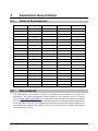
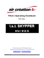
Pilot’s Operating Handbook
Trike Type :
l.s.t. SKYPPER
912 / 9 1 2 S
Aérodrome de Lanas, 07200 Aubenas, France
Telephone: +33 (0)4 75 93 66 66 • Fax: +33 (0)4 75 35 04 03
[email protected] • http://www.aircreation.fr
GDMUTA912-2G
Version 0010
1
1
Table of Contents
1
Table of Contents ................................................................... 2
2
Amendment Record Sheet .................................................... 4
2.1
Table of Amendments .......................................................................... 4
2.2
Amendments ........................................................................................ 4
3
General.................................................................................... 5
3.1
About this Document ............................................................................ 5
3.2
Drawings .............................................................................................. 6
Figure 3-1:
Skypper 912 in 3 Perspectives ...............................................................................6
4
Technical specifications – Performance .............................. 7
5
Instructions for use ................................................................ 8
5.1
Adapting Wings & Trikes ...................................................................... 8
5.2
Assembling........................................................................................... 8
5.3
Setting & Function of Controls.............................................................. 8
5.3.1
5.3.2
5.3.3
5.3.4
5.3.5
5.3.6
5.3.7
5.4
5.4.1
5.4.2
5.4.3
5.4.4
Throttle ...................................................................................................................8
Ground steering ......................................................................................................8
Brake ......................................................................................................................9
Parking Brake .........................................................................................................9
Ignition Switch and Dual Ignition Selector ..............................................................9
Fuel Cock ...............................................................................................................9
Choke .....................................................................................................................9
Ergonomics .......................................................................................... 9
Pedal Set ................................................................................................................9
Passenger Footrest ................................................................................................9
Harnesses ..............................................................................................................9
Baggage Storage .................................................................................................10
5.5
Preflight check.................................................................................... 11
5.6
Boarding ............................................................................................. 12
5.6.1
5.6.2
5.6.3
General .................................................................................................................12
Pilot in the Front Seat ...........................................................................................12
Passenger ............................................................................................................12
5.7
Start-up .............................................................................................. 12
5.8
Flight .................................................................................................. 13
5.8.1
5.8.2
Prior to Take-Off ...................................................................................................13
Take-Off................................................................................................................14
GDMUTA912-2G
Version 0010
2
5.8.3
5.8.4
5.8.5
5.9
Cruising ................................................................................................................14
Landing .................................................................................................................14
Parking .................................................................................................................14
Emergency procedures ...................................................................... 15
5.9.1
5.9.2
5.9.3
5.9.4
Power failure on take-off ......................................................................................15
Power failure at altitude ........................................................................................15
Restart the engine in flight ....................................................................................15
Engine fire ............................................................................................................15
5.10
Options ............................................................................................... 16
5.10.1
5.10.2
5.10.3
5.10.4
5.10.5
5.11
5.11.1
5.11.2
5.11.3
5.11.4
6
6.1
Parachute .............................................................................................................16
Dual Control for Instruction ...................................................................................16
Towing System .....................................................................................................16
Skis .......................................................................................................................17
HP (Cross Country) & 3F (Three Brakes) ............................................................17
Specific Use / Safety Instructions ....................................................... 18
Towing ..................................................................................................................18
Load Carriage, Survey Material, Data Transmission, Photography, Video
&c. ........................................................................................................................18
Sky jumpers ..........................................................................................................18
Skis .......................................................................................................................18
Appendix............................................................................... 19
Trike – Quality Form ........................................................................... 19
GDMUTA912-2G
Version 0010
3
2
Amendment Record Sheet
2.1
Table of Amendments
Amendment date
2.2
Affected sections
Affected pages
Date inserted
Signature
Amendments
The information in this manual is based on the data that was available at the time of its
publication. The latest amendments to this manual will be issued on the Air Création
website (http://www.aircreation.fr) in PDF format. This should be printed out and added
to the manual. The amendment table should at that time be updated with the appropriate
details and date. Therefore it is important for operators to check the website regularly for
any amendments that have been made. If any errors or omissions are found in this manual
please advise the factory.
GDMUTA912-2G
Version 0010
4
3
General
3.1
About this Document
This manual is a legal document which is approved for use with Air Creation l.s.t.
SKYPPER trikes.
It must be used in conjunction with the particular wing’s operating handbook and the
Rotax 912 Owner’s Manual.
It must remain with the aircraft, and not be amended or altered without authority from Air
Creation.
All pilots should read this manual before flying as pilot in command of the aircraft to
which it refers.
This manual is not intended to teach you how to fly the aircraft. Learning to fly should be
accomplished under the supervision of a suitably qualified flight instructor experienced in
flying this type of aircraft.
What this manual will do is provide the information necessary to a qualified pilot for the
safe flight of this weight-shift aircraft.
GDMUTA912-2G
Version 0010
5
3.2
Drawings
Figure 3-1:
GDMUTA912-2G
Skypper 912 in 3 Perspectives
Version 0010
6
Technical specifications – Performance
4
912
912 S
Empty weight (standard)
168 kg
370 lbs
170 kg
375 lbs
Maximum weight without wing
417 kg
919 lbs
417 kg
919 lbs
Ultimate load factors at max weight
+6g -3g
+6g -3g
Limit load factors
+4g -2g
+ 4g - 2g
Fuel tank capacity
55 Liters
14.5 US Gal
55 Liters
14.5 US Gal
Engine
Rotax 912 UL
Rotax 912
ULS
Maximum power
59.6 kW
73.5 kW
Maximum rpm
5800 rpm
5800 rpm
Maximum continuous power
58 kW
69 kW
Rpm
5600 rpm
5500 rpm
Reduction drive
Mechanical
Mechanical
Ratio
1:2.43
1:2.43
Maximum propeller rpm
2400 rpm
2400 rpm
Measured noise level Lm at max. weight
82 dB
84 dB
Noise level corrected Lr
84.5 dB
86 dB
Height from ground H
35 m
115 ft
40 m
131 ft
Minimum height from ground for a noise level
inferior to 65 dB at maximum power
270 m
886 ft
360 m
1181 ft
To calculate the Lh loudness heard on the ground when the aircraft flies at the h height at
maximum weight and maximum rpm, use the following formula:
Lh = Lr – 22 log h/H
GDMUTA912-2G
Version 0010
7
5
Instructions for use
5.1
Adapting Wings & Trikes
In our current production, the two-seater wings Fun 450, Kiss 450, iXess, NuviX and
BioniX may equip l.s.t. SKYPPER trikes.
5.2
Assembling
Assemble the wing as indicated in the Pilot’s Operating Handbook of the wing, rest it on its nose
faced into the wind.
2. Wheel the trike behind the wing, in the keel axis, remove the windshield, pull the upper beam
down and take the front strut out.
3. Raise the upper beam, push the hang point into the hang bracket, position the Ø10 hang bolt,
install the butterfly nut, tilt the lever back in order to tighten the plates, and secure with the safety
ring.
4. Slip the backup fastening cable through the belt loop at the kingpost level, make one turn around
it. Slip it through the belt loop again and fasten it to the trike upper beam. The backup fastening
cable should pass under the tensioning cables and between the keel and the fine cord of the
CORSET for the NuviX and BioniX wings. This operation secures both the trike to the wing and
the wing crossbar tensioning system.
5. Raise the wing nose by pulling the trike back or by slipping the control bar until the keel meets the
upper arch.
6. Attach the front strut between the plates at the top of the upper beam using the bolt, the butterfly
nut and the safety ring.
7. Hold the control bar and lift the wing. The front tube base is fixed to the frame at windshield level.
8. Set the safety bolt of the upper beam (above the passenger seat), screw the butterfly nuts, then slip
the safety rings into the drilling of the bolt.
9. Set the bolt connecting the front tube with the lower beam; screw the butterfly nut, and secure
with the split ring.
10. Assemble the windshield using the ¼ turn plastic screws.
11. To disassemble, reverse the assembly operations.
1.
5.3
Setting & Function of Controls
5.3.1
Throttle
The primary throttle control is a foot throttle which is connected to the right foot pedal.
This is activated by pressing the foot pedal. There is also an additional hand throttle
which is located on the right side of the instrument panel. Both throttles work in the
conventional manner, i.e. forwards to increase power. An addition foot throttle may be
fitted for the rear seat occupant/instructor.
5.3.2
Ground steering
The nose wheel is steered by the foot pedals via cables. They work in the normal weight
shift aircraft manner – i.e. push right to go left.
Rear seat steering is also an option and operates in the same manner via a rear steering
bar and linking cables.
GDMUTA912-2G
Version 0010
8
5.3.3
Brake
Push the left pedal forward to apply the hydraulic disc brakes upon the wheels.
5.3.4
Parking Brake
Push the brake pedal (brake action), lift the parking brake rack located behind the pedal,
on the left of the main panel and slowly release the brake pedal. The rack is blocked. The
parking brake is spring loaded and automatically returns to the off position when the
brake pedal is pressed again.
5.3.5
Ignition Switch and Dual Ignition Selector
The ignition switch is placed on the control panel and turns on when pushed up; it turns
off when pushed down.
The dual ignition selector, also located in the control panel, enables selecting one of the
two ignition systems whose switch is in the up or down position. Both may be selected if
both switches are in the intermediate position.
5.3.6
Fuel Cock
The fuel tap is located near the upper arm of the right choke lever. The tap is positioned
so that it is open when the tap is in line with the fuel line and shut off when the tap is
perpendicular to the fuel line.
5.3.7
Choke
The choke lever for the engine is located to the right of the passenger seat, near the cap of
the fuel tank. It helps start a cold engine. The choke is activated by pulling up.
5.4
Ergonomics
5.4.1
Pedal Set
The position of the foot pedals can be adjusted to provide the most comfortable and
efficient piloting position.
The range of adjustment of the rudder pedal is up to 2 inches (5 cm) with 2 horizontal
positions.
The rudder pedal is moved by pulling back the fork axel and setting it in the desired
position.
5.4.2
Passenger Footrest
The footrest can be adjusted by rotation on its axis on the bottom strut. Two positions
1.5 in (4 cm) apart may be set according to the size of the passenger.
5.4.3
Harnesses
The Skypper is fitted with lap straps which utilize conventional airline-type buckles.
There are also additional inertia reel shoulder harnesses for the pilot and passenger which
attach to the lap strap buckles.
GDMUTA912-2G
Version 0010
9
5.4.4
Baggage Storage
Baggage can be stowed in the following areas:
A storage basket is located in the cockpit fairing under the pilots’ legs. Maximum load for is 22
lbs (10 Kg).
In the stowage area under rear seat. Maximum load in this area 33 lbs (15 Kg).
Rear seat stowage bag. This can be fitted when flying solo and is secured by webbing straps. Max
load 65 lbs (30 Kg).
Document pocket behind the back of the front seat. Max load 2 lbs (1 Kg).
Loads carried in these areas must be accounted for when working out the takeoff weight
of the aircraft.
GDMUTA912-2G
Version 0010
10
5.5
Preflight check
The following is a brief summary of the minimum pre-flight inspection, which assumes
that the scheduled maintenance checks outlined in the maintenance manual has been
performed.
If you are unsure, it does no harm to increase the number of items in your inspection in
accordance with the recommendations of the maintenance manual.
1.
2.
3.
4.
5.
6.
7.
8.
9.
10.
11.
12.
13.
14.
15.
16.
17.
18.
19.
20.
21.
22.
23.
Check the wing as indicated in the user’s manual.
Ignition switches and master switch OFF
Check the trike-to-wing fastenings and every safety device (bolt, nut and split ring).
Check that the pylon backup cable is correctly positioned and fastened.
Check the lower and upper fixing of front strut and every safety device (bolts, nuts and split rings).
Pylon fixation bolts secure and pinned.
Engine bonnet secured
Engine mount, rubber mounts, security and condition
Check the propeller, the exhaust, its fastening springs and rubber mounts, the air filters and hoses,
the carburetors and rubber flanges for security and condition.
Check the fuel tank, sight gauge and cap, the fuel filter, the fuel valve and the fuel hose for
security, integrity, and leaks.
Check the coolant level in the expansion tank located behind the passenger seat and any leakage
from hoses. Make sure the water cooler box is unobstructed.
Check the oil level with the gauge placed in the bottle located on the left rear flank of the trike,
under the passenger seat.
Check that the oil cooler box entry of the radiators is unobstructed.
If there may be water in the fuel tank (due to condensation, fuel quality) eliminate it with the help
of the drain tube whose end is fixed behind the passenger seat and fitted with a spigot. To drain,
remove the end of the tube, place it in a recipient under the reservoir and open the spigot. Close
the spigot and refit the tube after draining.
Lock-to-lock check of steering, brake lines, position and fixing of pedals, tires condition and
inflation.
Rear wheels, brake lines and wheel spats security and conditions, tire and suspension units
condition and inflation.
Security of seat cushions and backrests.
Condition of seat belts and function of buckles
Check the storage bags and the bag placed on the passenger seat while flying solo.
Hand and foot throttle operation and friction. Move the throttle pedal back and forth to check that
the piston on each carburetor returns to idle position. If you do not hear this particular noise, the
cables may be stuck. Starting the engine under these conditions may cause loss of control of the
aircraft and cause a serious accident, or even death, due to the strong push after starting.
Brake pedal operation
Security of windscreen
Loose item check in cockpit fairing (if installed).
GDMUTA912-2G
Version 0010
11
5.6
Boarding
5.6.1
General
When flown solo, the aircraft must be flown from the front seat only !
A protective helmet must always be worn, fit correctly and secured. A positive lock must be fitted
to the visor and be engaged during flight.
Check that neither pilot nor passenger has any objects that can fall out of their pockets.
Ensure articles of clothing, such as gloves, scarves, glasses/sun-glasses, as well as cameras, maps,
knee boards, portable navigation instruments etc. are secured, no loose objects in the cockpit !
Any loose object is likely to pass through the propeller arc, destroy the propeller or/and throw
debris through the sail and seriously threaten the safety of the aircraft and its occupants.
Occupants with long hair, particularly in the back seat, must have it tied up to ensure that it cannot
reach moving or hot parts of the engine.
5.6.2
Pilot in the Front Seat
When flying solo, the aircraft may only be piloted from the front seat!
Get on board from the left-hand side of the trike. The pilot should step over the lower
strut while holding the front strut with the left hand. The reverse operation is
recommended to exit the trike.
5.6.3
Passenger
Once the back of the pilot seat has been pulled down, the passenger embarks from the left
of the trike by placing his left foot on the rear gear strut and holding the upper strut with
the right hand.
Passenger minimum briefing:
Do not touch instructor foot throttle or ignition switch, if fitted.
Do not touch the control frame and cables.
Fold arms, or rest them on knees.
Do not under any circumstances, touch the hot and/or rotating engine parts directly behind.
5.7
Start-up
Rotating propellers are almost invisible and can cause injury or death. Ensure that
all spectators/children/pets are kept well clear of the propeller arc. On certain
surfaces, stones can bounce into the propeller blades and become projectiles. Do
not start an engine if any loose stones are in the vicinity of the aircraft with any
spectators present at all.
1.
2.
3.
The ultralight has to be in a secure zone; make sure it is facing an unobstructed place while taking
into account the effect of the blast of the propeller upon the surroundings.
Fill the fuel tank (please refer to the engine user’s manual for fuel details). The gauge is located on
the right at the front of the tank.
Make sure the fuel valve is open (see 5.3.6).
GDMUTA912-2G
Version 0010
12
4.
Sit in the trike, pilot pilot in the front seat, parking brake engaged, safety belt fastened. Pull the
buckle to release the winding system of the shoulder straps and fix it on the locating lug provided
for this purpose, on the belt’s side.
Safety belts should be placed at hip level and tightened correctly. Safety belts
fastened at abdominal level may cause internal injury in the event of a violent shock.
5.
6.
7.
8.
Open the choke control (from cold).
Set the throttle lever and the foot pedal on “idle” position.
Put the general ignition switch on the “on” position.
Make sure no one is standing close to the propeller and say aloud: “Clear prop”, pause, then turn
the key of the master switch to the “start” position. Release the key once the engine has started.
(Activate starter for max 10 seconds only, followed by a cooling period of 2 minutes). Be prepared
to cut the motor immediately in case of runaway due to a blocked accelerator mechanism.
9. Once the engine has started, set a suitable warm up RPM and progressively reduce choke. Turn on
the electronic instruments by means of the control panel switch. Oil pressure must rise within 10
seconds and the warning light for battery charging must switch off. Only taxi when the engine has
reached a reasonable temperature. Turn the choke down once the engine has been running a few
seconds.
10. Release the parking brake by a short push on the brake pedal.
If the brake pedal has been pressed too lightly and the parking brake has not been
released, the pilot may not feel its action during taxiing, but the takeoff distance will
be much longer.
5.8
Flight
5.8.1
Prior to Take-Off
Your ultralight must be in good flight condition, that is to say maintained and used as
prescribed by Air Creation. The take-off weight must never exceed 992 lbs (450 kg).
1.
2.
3.
4.
5.
6.
7.
8.
9.
10.
11.
12.
13.
14.
Harnesses and helmets secure.
Clothes, personal effects & accessories attached; pockets empty or closed.
Controls full and free.
Parking brake disengaged.
Lower and upper fixing of front strut, blocking pin of the rear upper strut, trike-to-wing fastenings
in position and secure.
Instruments all serviceable, reading correctly.
Choke off.
Fuel on, sufficient for the flight, cock open.
Ignition checked for mag drop and selected to both. The test must be performed at 3000 rpm. The
rpm drop must be less than 300 rpm with a difference of 120 rpm max between the two ignition
systems. Put the switch selector back on the intermediate (both) position 1+2 after this test.
Minimum parameters of engine temperature reached. The SKYPPER 912 is equipped with an
automatic carburetor heating system intended to help to prevent icing. This device uses the water
of the cooling system to heat the carburetors’ intake. Full efficiency will not be reached until the
water temperature in the cylinder heads reaches 80°C.
Trim or CORSET (if fitted) set to takeoff position (check applicable wing manual).
Wind speed and direction checked, and suitable for safe take-off on selected runway.
All Clear, all around the circuit, final clear and runway unobstructed.
Power, check full power is achieved early in the take-off run.
GDMUTA912-2G
Version 0010
13
5.8.2
Take-Off
Use the foot pedal to progressively attain full throttle when carrying a passenger.
When flying solo, 3/4 throttle will be enough for take-off and climbing. Use full power
only under critical conditions (short take-off runs, obstacles and high altitude flight). In
this case never reduce or cut the engine below the 300 ft (100 m) altitude to avoid
dynamic stalling.
The recommended speed for initial climb is indicated in the wing’s manual.
5.8.3
Cruising
Keep the aircraft level with the throttle between ¼ and full power, depending on given
airspeed and load. Avoid repeated and sudden power climbs and idle dives to prevent
quick engine temperature changes, which could damage the engine by thermal shock. To
avoid permanent pressure on the right foot throttle, push the hand lever on the right of the
control panel until it resists, then release the pedal. To return to pedal control, press the
pedal until it resists, then pull back the lever.
Fuel tank content is easy to check from pilot’s and passenger’s seats as the tank has a side
gauge, or the optional electric gauge. A landing should be considered before tank
contents reach 1.5 US gallons (5 liters). This allows approximately 30 minutes reserve of
flight at economical cruising speed.
5.8.4
Landing
The landing approach is best executed using the foot throttle pedal and both hands on the
control bar. At maximum load, keep the throttle at ¼ of full power when on final to
facilitate flare-out. Throttle back when the wheels touch the ground.
The recommended approach speed is indicated in the instruction and maintenance manual
of the wing.
5.8.5
Parking
1.
2.
3.
4.
5.
6.
7.
Park the aircraft in the crosswind and place the extremity of the half-wing in the wind on the
ground.
Turn off electronic instruments.
Stop the engine with the ignition switch.
Cut the battery power using the key.
Block the parking brake.
Block the control bar on the front strut of the trike using Velcro strap.
Leave the trike, pilot first, then passenger, and always to the left side.
GDMUTA912-2G
Version 0010
14
5.9
Emergency procedures
5.9.1
Power failure on take-off
Should the power unit fail after take-off while still at low height, maintain aircraft control
and safety approach speed, and land the aircraft straight ahead without attempting to turn
back to the landing field. If time allows, set ignition switch and fuel cock off.
5.9.2
Power failure at altitude
If the engine fails for any reason, prepare for landing and carry out the emergency
procedures as follows:
1.
2.
3.
4.
5.
Immediately establish the best glide angle speed.
Check for suitable landing sites. Choose a number of preliminary options if possible.
Set ignition and battery switches off. Close the fuel cock.
Check that pilot and passenger seat belts are tight and secure.
Check wind direction, either by natural indications such as smoke rising or by judging drift of
aircraft over the ground.
6. Choose the most appropriate landing site.
7. Set up an approach as accurate as possible into wind.
8. Remember that your aircraft cannot be heard. Check that no one is on the landing site.
9. Finalize your approach, deciding upon the best landing free of any obstacles.
10. Use a short landing technique.
11. Evacuate the aircraft as quickly as possible, encouraging the passenger to do the same.
5.9.3
Restart the engine in flight
1.
2.
3.
4.
Set the ignition switch to ON.
Use the choke in case of a prolonged stop.
Use the starter with the key.
Adjust the throttle and turn the choke off.
Restarting in flight may be hazardous. Keep enough altitude and stay close to a
landing field.
5.9.4
Engine fire
Should an engine fire occur during flight:
1.
2.
3.
4.
Maintain your flying speed.
Set fuel cock off.
Set ignition and battery switches off.
Carry out the emergency landing procedures as above.
GDMUTA912-2G
Version 0010
15
5.10
Options
The standard empty weight used as reference to calculate the empty weight of the trike
does not include the options stated hereafter. Thus it is necessary to subtract from the
payload, detailed in particular wing’s Pilot Operating handbook, the weight of each
option installed.
5.10.1
Parachute
The Skypper can be equipped with a pyrotechnic rocket parachute, inside the special
container placed under the passenger seat.
The parachute will slow the descent of both aircraft and occupants if a major problem
occurs (collision, flight envelope exceeded, etc.). It is advised to use it only as last
resort to save life or prevent injury.
Before starting the engine, the safety cotter pin placed on the launching handle should be removed.
Then it should be replaced after landing, before disembarking, to avoid unintentional firing. It is
recommended to link the engine key with the safety cotter pin, so its removal while using the trike
cannot be forgotten.
Before firing the parachute it is advised, if altitude allows, switching the engine off to avoid
damaging the main bridle with the rotating propeller.
If you cannot stop the engine, it will be stopped at the same time you pull the handle of the
parachute, due to the switch integrated on the handle fitting.
The activating of the rocket motor is made by pulling the red handle located between the pilot’s
legs, on the seat frame.
A strong pull on the handle is needed, at maximum available length.
Always inspect bridle connection points and activation cables before flying; do not
modify them. When rigging the wing, bridles must be fixed with the link shackle.
The recommendations concerning inspection, activation and unloading of the
rocket, maintenance periods and overall care are stated in the user’s manual
provided with the parachute.
The parachute does not change the flight behavior of the aircraft but its weight reduces
the payload by 22 lbs (10 kg).
5.10.2
Dual Control for Instruction
This option allows for control of the ground steering and the engine power from the rear
seat. It allows full control from the rear seat of the aircraft.
Its weight reduces the payload of the SKYPPER trike by 2.20 lbs (1 kg).
5.10.3
Towing System
It allows streamers, advertising signs and hang glider towing. Pull the lever, set on the
left lower part of the seat frame, backward to release the towing cable.
The towing system reduces by 2.20 lbs (1 kg) the payload.
GDMUTA912-2G
Version 0010
16
5.10.4
Skis
This option allows use of the trike on packed snow after removing the wheels. The whole
series of wings supports this option.
The additional weight is up to 21 lbs (9.5 kg) and reduces the payload of the trike by the
same amount.
5.10.5
HP (Cross Country) & 3F (Three Brakes)
The HP option increases the possibilities of use on rough short fields. It includes a
hydraulic brake system on the 3 wheels with ultra-wide tires. Its weight is up to 20 lbs
(9 kg) and reduces the payload of the trike by the same amount.
The version 3F retains the smaller tires of the standard model, but is equipped with three
disk brakes.
GDMUTA912-2G
Version 0010
17
5.11
Specific Use / Safety Instructions
5.11.1
Towing
The towline must include a fuse gauged at 80 daN maximum in order to allow an automatic
release in case of over-tensioning.
Release the towline above a fully clear ground before landing.
Test systematically the releasing device of the trike before take-off.
The ideal speed for towing streamers is 47 mph (75 km/h). In the case of a glider, the speed should
be adapted to its performances. The emergency procedures stated in 5.9 remain applicable; the
towing must be launched above a fully clear field prior to landing. Characteristics, listed in the
applicable wing user’s manual, are diminished due to the drag of towing and flying level requires
a higher engine power. Minimum speed and stall speed remain unchanged.
5.11.2
Load Carriage, Survey Material, Data Transmission,
Photography, Video &c.
Install the loads to be carried on the passenger seat. The holding device has to support efforts up to
9 g forward, 3 g upward et 1.5 g laterally.
Limit the dimensions of the loads carried to avoid any contact, stress marks or blocking with the
wing structure and particularly with the inferior longitudinal cables.
Mounting any kind of camera at the tip of the wing is possible up to a maximum weight of 2 kg if
you install a counterweight at the extremity of the opposite wing. The inertia of the wing on its roll
axis will increase.
The emergency procedures stated in chapter 5.9 remain applicable.
5.11.3
Sky jumpers
Training on the ground is absolutely necessary before take-off.
The skydiver always leaps from the back seat, in normal tandem or "sidesaddle" position, body
perpendicular to the trike axis.
The pilot cuts the engine before the preparatory step of the jump. The skydiver may use the wheel
leg gear as a step.
The emergency procedures stated in 5.9 remain applicable. If altitude allows, the sky jumper will
return to normal position before landing.
5.11.4
Skis
Mounting the ski system in place of the wheels reduces performance globally due to the increase
of drag.
The lack of brakes makes perfect speed management necessary and makes stopping possible only
on a flat surface, engine off.
The emergency procedures stated in 5.9 remain applicable.
GDMUTA912-2G
Version 0010
18
6
Appendix
6.1
Trike – Quality Form
Anxious to ensure the perfection of our products, we have set up a sequence of controls
covering all steps of production. We are continuously working on their improvement and
we are in need of your help.
Please return this reply form accurately filled in if you find any issues or problems
concerning your trike that could affect its quality or finish, even if it is a minor matter.
Name
Address
Telephone
E-Mail
Type of Wing & Trike
Delivery Date
Trike Serial Number
Engine Serial Number
Distributor
Hours Flown
Problems noticed: (explanations and/or drawing)
GDMUTA912-2G
Version 0010
19
Aérodrome de Lanas, 07200 Aubenas, France
Telephone: +33 (0)4 75 93 66 66 • Fax: +33 (0)4 75 35 04 03
[email protected] • http://www.aircreation.fr
GDMUTA912-2G
Version 0010
20