1
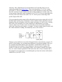
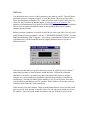
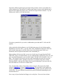
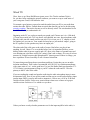
Beginners Guide to
using Slow Scan TV.
More than you ever wanted to know about SSTV.
Revision 1.0
By Guy Clark
Copyright 2002
Contents
1.
2.
3.
4.
5.
6.
7.
8.
9.
Introduction
Receive Only
Software
•
•
•
•
•
•
Acoustic
Wired
Speakers
Isolation
Transformer
Level and Mounting
•
•
•
•
•
•
Selection
Sound Check
Download
Installation
Level Adjustment
Slant Adjustment
•
•
•
•
•
•
Web Sources
Scanners
Video Capture
Cameras
Warnings
Software Manipulation
•
•
•
•
Isolation
Attenuation
Connectors
RX-TX Switching
•
•
•
•
•
•
•
VOX
PC Control
Serial Port
Relay
Optoisolator
TX Display
Disable Switch
TX (Foam method)
Find & Make Pictures
Wired TX
Auto PTT
Advanced Features
Examples of Pictures
Introduction
So you are new to slow scan TV but you would like to try it out. Maybe you are just
curious to see what it is all about. That’s OK. You can check it out without spending an
arm and a leg. I’ll show you how in the following articles.
Of course if you want to, you could just buy a ready-made interface. They are available
from several sources with varying degrees of abilities and problems. You will still have to
follow the instructions in their manual and you might still have to build a cable or two.
Well, let’s get down to work. It doesn’t take much effort to just receive SSTV. I think it is
ultra simple compared to building even a simple circuit like a code practice oscillator. It
does require a few things like a radio and a PC. I assume you have those things, but if not,
don’t give up yet.
Used PCs are more affordable than ever, and more powerful too. You should start with at
least a 200 MHz Pentium. It can be done with a 486, but you would have to run older
software like JVFax using a HAMCOM interface in place of modern sound card
hardware/software. If you just have to, email me and maybe you can convince me to send
you the information.
If you have no radio, how did you become a ham? Sorry, I couldn’t resist the temptation.
If you have no radio, you might be able to use a scanner or a short wave receiver. The
local group I send pictures with have great fun on 146 MHz repeaters. It would be easy
for a scanner owner in my town to ease drop on our pictures. A SWL rig should work fine
on HF if it is one of the better ones that is capable of receiving single side band (SSB)
from hams. The PC doesn’t care what the radio is. All it does is takes the audio and
converts it into a picture. Although a $60,000.00 Collins station would work great, you
would probably not notice much difference using a Kenwood TS-520. (Yes, Collins still
makes HF gear, I work for them.)
Receive Only
OK, you got a radio and a PC now. What is the fastest, simplest way to receive SSTV?
You could plug a PC microphone into the sound card mike jack and set the microphone
near your radio speaker. Install the software, and it should work. I just tried it myself to
see if it would work. It did, but the results are not fantastic. See my samples of pictures to
see it, together with the same picture using an interface wired directly. The interface is
described in the next few paragraphs. Anyway, using a microphone might work on your
PC, but I do not advise using this method to receive SSTV. It is so easy to do it the right
way, I don’t know why anyone would try it the wrong way.
Caution: Be sure to read all of this section before you try it out, OK?
It is much better to try a hard-wired connection. That way, if you sneeze or your phone
rings, it will not ruin the picture. The idea here is to send the SSTV audio signal to the PC
without using a microphone.
Get a piece of cable, preferably one with a 1/8th inch (3.5 mm) stereo mini jack on both
ends. That is the size and style of plug that fits most sound card jacks. Make sure it is
long enough to reach your radio without being a trip hazard. The cable should be shielded
microphone cable, made to withstand RF fields like you might find in a ham shack. Plug
one end into the PC sound card. Use the microphone jack or, if there is one, into the linein jack (preferred). The radio end should connect electrically to your radio speaker. I
don’t advise soldering your new wire right onto the speaker inside your radio. That is not
very user friendly.
Nearly all radio speakers are too small. The radio will sound better with a slightly larger
speaker. This has nothing to do with SSTV, but it will work to our advantage. Even an
old abandoned AM car radio speaker would probably be an improvement. Put it in a box,
wood is better than plastic. That way the box acts as part of the sounding board. Looks
better too. Low wattage home stereo speakers are also a good choice. But don’t use high
class, high dollar audiophile speakers. Those Klipsch towers probably need more than a
few watts to drive them. Modern HAM radios rarely provide more than 3 watts of audio
drive.
So, now that you are using an external speaker, it probably plugs into the back of your
radio at a jack labeled EXT SPKR. You can solder your new SSTV cable wire to the
speaker wire that plugs into the back of your radio. I prefer to use a ‘Y’ adapter in place
of soldering two cables together. That makes it easier to disassemble later if you want to
move things around.
You may have a standard size of external speaker jack on the radio. It is typically 1/8th
inch (3.5 mm) also, but not stereo. But wait. Your radio is not stereo? Mine is not either.
How did we start with a stereo cable at the PC and end up mono at the radio? Really, it
doesn’t matter. If you are soldering up your own connectors, just use the ground (shield)
and tip wire. The third wire from the stereo plug can be capped and stowed for later use.
This is the wire that connects to the ring of the stereo plug. If you are mix and matching
plugs and jacks, don’t worry about it. All that will happen is that one input channel of
your sound card will see ground. We don’t care because all SSTV software looks at the
other channel. It will not hurt a thing.
OK. you got cable. This might work fine. Here comes the tricky part. Under the worst
circumstance, you can pop a fuse, blow a breaker or even burn your house down. This is
not good. Doubt me? Oh ye of little faith. Keep reading.
The PC and radio will probably be running on house current (AC mains). If there is a
problem in the design, implementation or safety of the power supplies there can be a big
surprise. It can happen. It has happened. It is not likely but, do you want to take the
chance? I don’t want you to. Hopefully both power supplies will be DC isolated from the
AC line via a transformer. I have seen cheep PC supplies that had no isolation
transformer. And, I have seen power supplies develop a short from AC hot to chassis with
out shutting down or blowing fuses.
Even a properly wired PC and radio can have a ground loop problem. There are no
perfect grounds. It is even worse using extension cords and power strips. The IR drop in
the house wiring can be enough to cause hum problems. Any wire, no matter the size has
a finite resistance. That resistance WILL cause a voltage drop. There are many web sites
that cover these subjects from a power distribution and broadcast audio standpoint.
It is easy to check for this problem and almost as easy to design around it while being
safe. Just use a voltmeter to check the PC chassis to radio chassis voltage before you
hook anything up. Even better, assume the problem always exists and build your shack to
withstand it. That way it doesn’t mater.
The way to do this is to use an isolation transformer in your radio to PC cable. That is
what I recommend, ALLWAYS ! An isolation transformer will be impervious to AC and
DC voltage drop between primary and secondary, up to at least 250 volts. The
transformer will also eliminate ground loop problems that create hum. You just have to
remember that once you isolate with a transformer, ALL your lines between the PC and
radio must be isolated. If not, you are back to the same problem, popping fuses and all
that.
What transformer works best? Audio of course. Oh, which one? The one that best
matches your radio and PC. If you hook up to the radio speaker, the impedance is
probably between 4 and 20 ohms. If you were using an auxiliary output point, I would
guess the impedance to be between 600 ohms and 10K ohms. The specific amount
depends on the manufacturer. Well, that is the primary side of the transformer.
The transformer secondary goes to the PC. If you connect to the line-in jack of the PC, the
impedance is on the order of 10K ohms to 50K ohms. If you are using the microphone
jack, plan on some thing lower like 600 ohms. The exact values are not critical. Even if it
is a decade off, you will probably not notice a difference.
Generally, I have found that one of two transformers will work OK. Those two are
commonly available from Radio Shack. They are stock numbers 273-1374 (1:1 turns
ratio) and 273-1380 (8:1000). The first one has an audio impedance of 600 to 900 ohms,
but a DC resistance of only 60 ohms if measured with an ohmmeter. In other words, you
can not measure impedance with an ohmmeter. Use 273-1374 if you are connecting to an
accessory (line level) output of the radio. Use 273-1380 if you are connecting to the
speaker output of the radio.
If you are using the speaker output of the radio and not an accessory output, the level will
be rather high. You may have to attenuate it with a variable resistor, especially if you are
dumping it into the microphone jack of the sound card in place of a line-in jack. Looking
back at all of my schematics to see what worked best I find that there were many
varieties. Some were 1 K ohm, some were 10 K ohm. On one, the 8 ohm transformer
(radio side) loaded down the speaker, so I added a 1 K ohm variable resistor in series with
the 8 ohm transformer winding. Not technically correct, but it worked.
Damage to your transformer may result if dropped, kicked or chewed on by your pets. To
protect it from damage, you can mount the transformer in just about anything. I like to reuse common household containers like a pill bottle, a metal Band-Aid box or even a
discarded plastic food container. If the transformer is not near a power supply or PC
monitor, I would not worry about magnetic fields. A few inches is enough. Closer than
that, use a metal container grounded to ONE side of the cable. Chose a container that is
big enough for your whole project, remembering that you may later want to add transmit
capabilities to your SSTV set up.
Software
You should now have a receive cable connecting your radio to your PC. That will do no
good until you have a program in the PC to view the picture. There are at least a half
dozen good programs available for PC’s (and at least one each for MAC and Linux). To
chose one, do a search on an Internet engine, or visit my reviews of software. For
purposes of demonstration I will detail use of MM-SSTV. There are many other software
choices. I do not mean to belittle the others by not including them, but it is hard to
compete against freeware.
Before you chose a program, it would be a good idea to check your cable. It is easy to do
using Windows built in programs. Look for: C:\WINDOWS\SNDREC32.EXE You may
find it installed under Start - Programs - Accessories - Entertainment. Different versions
of Windows may call the Sound Recorder by slightly different names or put it in a
different location.
Turn on your radio and set it up for a little noise or tune in a QSO. For now it doesn’t
matter what you tune in. Start Windows Sound Recorder. Click on the red button
(Record). Let it run for a second or two, then click on the black square to stop the
recorder. As it was recording you should have noticed the green line waving like an
oscilloscope. Click the play button (in the middle), to see if your PC hears your radio.
You should hear something in your PC speakers. Don’t blame me if you hurt your ears
with the volume turned up. I just warned you.
If this doesn’t work, don’t despair. There are many things that are easy to fix that would
prevent your PC from hearing your radio. First see if you can get any sound out of your
PC speakers. Then check your sound card makers web site for help or newer divers.
Sometimes different audio inputs get turned off by accident. Look in your taskbar for a
yellow speaker icon. The task bar is usually at the bottom of your screen and the icon is
near the clock. Right click on the icon. Left click on ‘Open Volume Controls’. Try UnMuting some items or click the help menu.
If you have gotten this far you can be confident that your radio and PC will work OK
together.
After you decide which software to use, find the home page web site for that product.
Bookmark it (save the U.R.L.), you may need it later. Find the download site. This may
not be on the same page or even the same server as their home page. Before you
download, check for special instructions. Don’t download yet.
Many modern web browsers allow you to save a local copy of a page from the World
Wide Web. This is a real neat feature. To use it, find the page, click on File, Save As, and
give it an identifying name so you can find it again. The type of file should be -.htm- or -.
html- . The browser will not only save the words on that page, but may also save any
pictures as graphics, tables, and other visual items. It puts the pictures into a folder
(directory) that is a sub-set of the folder where you saved the page. If you move the file,
move the folder too. It will have a similar name.
Now, download the software. Remember where you put it. The current (late 2002)
version of MM-SSTV is named: MMSSTV108.exe . The first link is to my buddy Jim
W0EB, who mirrors the other site for download. Either should work fine with the same
version files. The only difference should be the speed of download depending on your
location and server.
Save a copy of your download on floppy or in a safe place. You never know when a
friend will want it too. MM-SSTV version 1.08 does fit on one floppy disk.
After you have downloaded the program, you will need to install it. Before installing any
program, shut down anything you have already opened. To be sure, give your computer a
three finger salute (Control + Alternate + Delete). That opens the task manager. It will list
any running programs. The only two you must leave running are Systray and Explorer.
The others you can terminate by highlighting (one mouse click) and then click on ‘End
Task’. You might want to risk leaving some programs running, if you know what they
are. Back ground programs like anti-viral software, registration reminders and even
banking programs leave little residue programs running after they are closed. Most begin
again the next time you boot up (Start your PC).
Open Microsoft Explorer, the file manager. Locate the file, MMSSTV108.exe. Double
click on it. Follow any installation procedures. Here is a note from the MM-SSTV web
site: ‘If you are upgrading from a previous version, make sure that you select your current
program folder for installing the new files. The install program will not over write your
configuration or log files. However, that being said, it never hurts to save a backup, just
to be safe.’
When you are done installing the software, I think it is a good idea to re-boot your PC.
Now, finally, start your software. Get ready for your first picture but don’t expect too
much. Why? Well, we need to adjust the audio levels and adjust out the slant error. You
may have to change the setting quite a bit, just to see the picture.
Audio level adjustment is confusing to start with, but the hardest problem I have faced is
getting use to the conventions. I mean, Windows uses the words playback and record to
mean ‘send to the speaker’ and ‘receive from the microphone’ respectively. I prefer to
think of playback as a receive function and microphone as a transmit function, yet that is
incorrect. I guess it is all a matter of perspective. To receive a SSTV picture you must use
the ‘in’ jack of the sound card to get it into the PC. To transmit, you send the picture
audio out of the PC to you radio.
Well, to set the levels open the Windows Play Control (C:\WINDOWS\Sndvol32.exe).
Windows normally installs a little yellow speaker icon near the clock on your task bar.
Right click the speaker and select ‘Open Volume Controls’. Not all devices may be listed.
You can change them with Options, Properties.
When you receive a picture you may need to adjust your input level. Click Options,
Properties, Recording, then click on OK to see those levels. This might be labeled LineIn, Microphone, or something else, depending on Windows, the sound card you are using,
and which input jack you are using. You may have to Select which input device your
sound card runs from. The level (slider) position will vary. Of course if you are using a
radio speaker as a source and you have it plugged into the mic input jack of the sound
card, I would expect that you need to set the slider near minimum (down most of the
way). In this example it might be better to use an auxiliary line level input instead.
If your radio is squelched (FM), you hear no audio. At the same time, your PC will read
no data. So when you set the receive audio level, make sure you have at least some noise
in the speaker (set squelch full counter clock wise).
You can adjust the slider for best picture. Actually it may not make much difference.
MM-SSTV is very forgiving. One older piece of software I used was specific. Its’
instructions said ‘Set the slider so that the audio level meter stays below half way’. In
MM-SSTV there is a water-fall display on the right top. Just to the left of that is a vertical
bar display to show the level of incoming signal. As long as that jumps around a bit
during reception of a picture, your Windows audio level is OK, leave it alone.
If you are reading along through my whole big encyclopedia (this collection of
documents), you may not be ready to transmit yet. Keep reading, I’ll get you there. It just
makes sense to put the TX adjustments here with the RX adjustments. After you install a
TX interface you can come back here to set it all up right. There are several TX interface
styles to chose from, easy & hard, but there I go getting off subject again.
Transmitting a picture uses a different level control. Open Play Control, click Options,
Properties, Recording, then click on OK to see those levels.(Mine is set up for Wave /
DirectSound / MP3 but I think that is very rare.) Make sure the device you are using does
NOT have a check in the mute box or you will never get it to work!
The position of the slider may be critical. Since you have no idea where to start, set it to
minimum (all the way down). Slowly increase the slider until you attain 100%
modulation, then back it off. Make darn sure you back off. If you don’t you can easily be
in violation of F.C.C. (or you governments regulatory body name here) regulations. How
to check for percentage of modulation depends on the mode, type of rig and other factors.
For a rough estimation on SSB, use power output or A.L.C.. Remember that SSTV is a
100% duty cycle mode. MANY hams set their HF rigs for 50% modulation on SSTV.
This saves their finals. Percentage of modulation, duty cycle and deviation are different
types of quantities. If you don’t understand it, please seek help form a local Elmer.
On FM, percentage of modulation is actually deviation, and it is always a 100% duty
cycle (not meaning RX / TX duty cycle). Very few hams have a deviation meter (I do, but
it is harder than heck to set up). For a rough estimation on FM, have a buddy listen to
your transmission using simplex. Ideally he should be far away enough so that his
receiver is not swamped by your transmitter. Alternately, have the receiving station use a
low antenna or dummy load to receive with. Talk to your buddy with a moderately loud
voice so that he can get a reference level. Then send a picture. Adjust the slider so that the
SSTV audio sounds slightly weaker than voice. If you try for MORE than voice, the
actual level may be distorting causing degradation of picture quality. There is a reason for
this.
Modern FM rigs (mobiles) work with a wide range of levels. They have to. In a mobile
you may have the window down, causing wind blast across the mic, or you may be
stopped in a peaceful area without background noise. The audio amplifiers in the rig
adjust the gain to compensate (like A.G.C.). With increased attenuation your rig may
introduce additional distortion. At a minimum, you may have a pumping effect caused by
the amplifiers always trying to keep up with changes. It is by far better to have 80%
modulation with no discernible distortion verses 99% modulation with 20% distortion.
I have kind of skimmed over the level controls in Windows. There is a lot I decided to
leave out. New operating systems and different sound cards would otherwise make my
discussion obsolete in sort order. The basics will continue to be useful for decades
however. Jim Barber N7CXI, has a excellent write up on sound cards on his web site,
Silicon Pixels. Click on Technical Info and scroll down to the bottom. Look for AN100 in
application notes.
OK, you got cable, you got software, you got LEVEL, what NOW?
SLANT
Remember, My example software here is MM-SSTV, other software will be different.
Hopefully this article will still be slightly useful with any program. Read the manual if
you can’t figure it out. Also, I thought about adding a few pictures here of MM-SSTV,
but I have decided not to. The words I have chosen and the program its self should be
enough. If not, try the download site for more help.
With MM-SSTV on your computer screen, you should see the 5 tabs or folders near the
top right. They are: Sync, RX, History, TX, and Template. Normally the program should
start with the RX tab. Click on the tab it to bring it to the foreground. Right below the
tabs is the part where you should see the picture paint down as it is received.
With everything turned on and running you should see the waterfall and level meter
jumping around. Wait for a picture. On HF, once the picture has started, don’t change the
VFO frequency, that would spoil the timing for slant. If you have to, re-tune and wait for
another picture. If you don’t know what frequency to find a picture on, try 14.230 MHz
for HF. For VHF or UHF, ask around. Different areas use different frequencies. In my
area of South Central Kansas we use 145.500 and 147.435 simplex with repeater NETS
on 146.715 and 146.820 MHz. WW5WOW near Tulsa uses 147.500 MHz.
It takes a relatively clean signal for a good picture. High signal to noise ratio, no QRM,
no QSB and so on. This seems contrary to SSB on HF, but remember that your brain does
a lot of signal processing when listening to a voice. With SSTV, what you hear is what
you get, QRM and all.
If the picture dose not start painting in 3 or 4 seconds, check the waterfall. It should be
jumping with one peak near 1200 & maybe other peaks. It might be that MM-SSTV just
missed the start sequence. If so, you can force start a picture by clicking on the correct
mode button (RX-Mode). Try Scottie 1, first (Scottie 2 on VHF, Martin 1 or 2 in Europe).
Now would be a good time for you to look at some of my samples of bad pictures. Not
that you want bad pictures, but if you know what causes a problem picture, you will be
that much closer to fixing problems.
It is rare for slant to be perfect with out any adjustments. Don’t expect it, unless you just
won the Irish lottery (then you don’t care anyway). The reason for slant and the need for
adjustment is that although sound cards work real well, they are not calibrated that
closely. They don’t have to be for music CD’s or other normal PC uses. They must be for
video synchronization of SSTV. The exact frequency of the crystal oscillator varies quite
a bit from one sound card to another, even with the same model of sound card. The good
news is, once calibrated, it does not change.
Once you have a picture (I use the word ‘picture’ loosely here) in the view screen of MMSSTV, click on the Sync tab. The picture might turn kind of dark (Reverse video) and you
might see multiple images in columns. Click on the yellow smiley face and wait a couple
of seconds for the calibration number. Write it down, you might need it later, well
probably not, that just sounds right. Quick, before someone sends another picture, click
on the ‘Mem’ button. The Mem button locks in the calibration so you don’t have to do it
again tomorrow. As long as the picture you just calibrated to was also calibrated well, you
should not have to mess with it again.
Just for the record, if the bottom of your picture is shifted to the right, that means that
your clock number is set to low. And visa versa.
Yep, that’s all there is to it. Click Sync, Click Smiley, and Click Mem. If I had told you
that in the beginning, you would not have learned much, so I drug it out, haw haw. Wait
there is more, maybe. That should work for most of you, but not all. It didn’t work for me
on the PC I’m using right now. My receive worked easy, as above, but my transmit was
still slanted. I believe this is due to dual clocks on the sound card (look for more than one
crystal on the board). These boards are becoming more popular with PCI slotted PCs.
This may also be related to how the sound card works, if it is full-duplex or not, and may
also be related to the software Loop-Back function in MM-SSTV.
MM-SSTV has the ability to off set RX and TX clocks separately. The following
information only applies to MM-SSTV:
Send a picture to your buddy or assisting station (they must already be calibrated). They
will click on the Sync tab, click the Smilley face, But they don’t click on Mem. That
would set their RX to your improper setting. MM-SSTV will give them an offset number
like -2.83 . They will then tell you: ‘set your TX to +2.83’. Notice the change in polarity.
In other words, you were 2.83 Hz low, so raise it by positive 2.83 Hz. You should then
click on Options (at the top, half way between File and Help), then Setup MMSSTV, then
the Misc tab. Toward the bottom left you will see the Clock parameters. The top window
is approximately 11 KHz, but the next window is the TX offset. This second window is
were you enter the +2.83 Hz. The 11 KHz is your RX clock. The offset is how far off the
TX clock is from the RX clock. Yes, you must set RX first.
There is an alternate procedure from the MM-SSTV help files. Use MS, I.E., or a newer
version of Netscape.
Next: The slackers way to TX.
TX (Foam method)
OK, you have seen your first picture, great. No doubt you will want to play with your new
toy a while. Go ahead. I’ll wait.
Back already? Ah, want to SEND a picture hu? It is easier than you thought.
Remember at the beginning of this encyclopedia, where I said to use a PC microphone
held up to your radio speaker to receive a picture? Yes, it works in reverse too. You can
just hold your radio mic up to your PC speaker to send a picture. My buddy James,
WBØOAO wrote a great article about it.
Well, you can do that. I don’t recommend it. You see, James has been around a LONG
time. He knows a lot of the tricks. I’m not so sure he didn’t invent them, right after he
invented dirt (Got ya!). OK, he isn’t that old, but he does remember P-7 phosphor. Of
course I do too. Never mind, you may be too young to understand. Doesn’t matter
anyway.
Tricks eh? Yep, well, read his article. It is all about acoustically coupling your PC speaker
to the radio microphone. To do that right you have to remove all outside audio. Stuff like
your dog barking, the phone ringing, your XYL complaining about the smoking coax, and
the fire engine that just pulled up. Well, I don’t want to steel his thunder, so either read
the article or read on to the REAL interface.
Find & Make Pictures
Before I go on to setting up a real transmitter interface, I think I should give you a leg up.
When you are ready to send a picture, you have to have a picture to send. Even though
most SSTV software comes with a couple of sample pictures, they just are not YOUR
pictures. Besides, they are boring. We have seen them before, a hundred times. How
many time can you watch Lucy Ball stuff candy in her mouth? It gets boring real quick.
You could just borrow pictures from other slow scanners. Send what you just received.
Again, boring. Well, how about pictures from a few weeks ago? Several slow scanners
have a web site to show off their accomplishments. Some of them have great, stored
pictures from weeks or years ago. See my links page for a place to start.
When you see a picture on the World Wide Web (WWW) that you want to keep, move
your cursor over it and right click the mouse. A menu will pop up giving you options you
can use. If you have MS I.E., click on ‘save picture as’. In other browsers the wording
may be slightly different like: ‘save image as’ or ‘save image’. When you click on the
save option, Windows will open a save-as folder-box. Make sure you chose the correct
folder (directory) to Save-in, that way you can find the picture once you have saved it.
Need a little more variety? Try doing an internet search for ‘wallpaper’. Use a search
engine like Google, Yahoo or Lycos. Go to the search engine and type in ‘wallpaper jets
flower’ and I bet you get hundreds of webs sites with pictures.
I am no lawyer, but under the Berne copyright convention, in some circumstances you are
allowed to use other peoples intellectual property. That statement is not carte blanche. We
are talking about ham radio SSTV here. What I meant is: As long as you do not profit
monetarily, I see nothing wrong with borrowing a picture or two. Be sensible. Where ever
practical give the author some credit (like me). That is really all they probably want, that
and enough royalties to retire to Bermuda. See also:
http://www.templetons.com/brad/copyright.html
http://www.benedict.com/default.asp
http://fmsstv.net/m/end.html#cop
Still boring, and not your own pictures. I think it is more interesting to see a picture of
you, your pets, or your Aunt Sue doing the Bunny Hop than copies from the web of
Venus De Milo. Oh, you HAVE pictures. They are just on Kodak paper. Well, get a page
scanner. You have the computer. Page scanners are not as expensive as they use to be.
Prices start from $50 US. Some chemical film developers will also put your photographs
on CD for you (at a small charge).
I also use a video capture card. That is a PC accessory that acts as a television tuner and
displays the picture on your PC screen. It is capable of having a scaleable window, even
full-screen size. The card fits inside your PC, has jacks for antenna (cable), S-video,
composite video, and stereo audio. I can use it to capture a still picture (for SSTV) or grab
motion video clips as an AVI file. Mine also has an FM broadcast tuner and will do video
conferencing like NetMeeting. They sell for around $50 US, but read the hardware
requirements before you buy one.
Of course if you are going to do pictures, you ought to have a camera. Any film camera is
a good start (if you have a page scanner). The better the camera, the better your pictures
can be. A lot of the slow scanners I know like the new digital cameras. They have a lot of
advantages over a film type. If you are thinking of buying one, shop around. You will
need one with at least 640 by 480 resolution. That is tiny by current standards. I like the
cameras from Sony with a floppy drive built in, but you can also get one with a CD writer
to store the pictures. The cheep PC cameras like the original ball from Logitech (Quick
Cam) had relatively poor resolution. I’ve used them, but even a cheep hand held digital
will out perform a PC camera.
Maybe you are a real artist, a regular Scott Adams (Dilbert creator). You can put your
etchings and charcoal drawings on your PC (with a page scanner) and send them on
SSTV. If you are a techie artist you may already be doing graphic work on PCs. If you
are, you are probably using Adobe Photoshop. If this is you, skip ahead a couple of
paragraphs.
Before we go on with making pictures I want to warn you about 3 things. These are the 3
most common areas of error that you as a new-to-SSTV person can make. They are:
Aspect ratio, fonts, and cheese cake.
Aspect ratio is a pictures ratio of width to height. Typically, for SSTV the ratio is 4:3.
That is 4 divisions wide by 3 divisions tall. 40:30 is the same ratio. Common pictures are
320:240 or 320 pixels wide by 240 pixels tall (same ratio). The error that most new slow
scanners make is that they resize a picture without maintaining the same aspect ratio. This
causes the picture to stretch in one direction or another. That is a dead giveaway that you
are new and you don’t really understand what you are doing. Sorry. If this is you, I know
you are not stupid, it is just that no one took the time to explain it to you before. Learn
how to avoid this mistake and you will move to the head of your class.
Fonts: The typeface or the appearance of the alphabet where each character has a similar
characteristic to the others. Examples: Arial, Courier, Times Roman. This is not an error,
but the miss-use of fonts can be an error. Here again, I don’t want you to look bad to
those of us who have been there and back again. By miss-use I mean, don’t use a font size
that is two small. SSTV looses resolution as it is sent and received. It may look good on
your screen, but will it still look good when it is received? Step back a few feet and look
at your screen again. If you have trouble reading it now, others will too, only worse. The
choice of font is as important as size. Some have vertical columns of empty space
(transparency). That makes the lettering blend in to a picture and disappear. Other fonts
are just plain hard to read. Some are frilly or overly busy. They are distracting and hard to
focus on. Color can affect readability too. Choose a color for lettering that contrasts with
the picture (its background).
Cheese Cake: No, not the kitchen kind. Those pictures of shapely but poorly clothed
ladies. Heck yes I enjoy them. I am an American male. But, well, wait. I’m going to let
some one else take on this one. The following is an excerpt from a newsgroup by
KA1EEC, and I could not have worded it better my self :
From: ‘Eric S. Johansson’ <esj@h...>
Date: Thu Oct 3, 2002 7:08 am
Subject: Re: [MM-SSTV] Re: File Uploaded
siggy200 wrote:
> And they like to send ‘cheese cake’ pictures a lot!
> Dirty old men HI!
some of them go way beyond cheesecake.
And I hate to sound like an old fart but babe shots make it make it dammed difficult to
do public demonstrations of slow scan TV.
I was doing a talk and demonstration on slow scan TV for my ham club when during the
live demonstration phase a nude photograph came across the screen.
one of my fellow club members handles battleship tours for Boy Scouts and uses the
opportunity to introduce ham radio to Scouts. After the meeting he told me that he was
going to invite me down to show off slow scan TV to the Scouts but after seeing the type
of pictures one can run into a slow scan, there's no way in hell he was going to includes
slow scan in his demos. The liability created by the babe shots was just too great.
Personally, I don't do as much slow scan because I'm tired of seeing pictures from the
Web as well as far too many babe shots.
Slow scan TV could be a wonderful mode to play with the people would use a little
commonsense about who's watching, and a little creativity in creating the content for their
programs.
---eric (ka1eec)
Well said Eric!
Personally, I ask myself: ‘Is this a picture that would upset my mother, or a Nun?’ You
never know who is watching (or listening).
Once you have pictures in your PC you will need to manipulate them. This takes special
software. You will need to have several functions right away. Things like convert format,
resize, crop, and adding text. MM-SSTV performs some of these functions like sizing and
limited text functions. There is a good instructional web page just for MM-SSTV. It was
written by Joe Hutchens, WJ5MH. I think you will soon need additional software though.
The first full featured graphics program that I used was a shareware version of LView.
That was a long time ago, but they are still in business and have continued to update their
product. You can buy a boxed Version of LView Pro, a boxed demo version, or download
the 21-day Limited Evaluation Version.
My next tool was Graphics Workshop. At the time, years ago, it had some nice
improvements over LView. It is still available (updated of course) to purchase or
download as shareware.
The high end program right now is Photoshop from Adobe. It is way too expensive for
most of us. It is THE program for professionals.
It is my opinion that anyone who needs professional image manipulation software, but
can not afford Photoshop, has only one choice. You must get Paint Shop Pro. Don’t wait,
don’t think about it. Just do it. Paint Shop Pro from JASC is fantastic. You will not
believe what you can do with this software. If you don’t believe me, just download the
trial version and use it a couple of times a week for 4 weeks. When the trial version time
runs out (30 days), you will agree and you will purchase the full version (Download $74
US, Boxed $82 US). Oh, and there is a Paint Shop Pro Users Group (PSPUG). They can
be real good at helping you with such powerful software.
Wired TX
Weee, here we go. More HARDware (grunt, snort - like Tim the toolman Taylor).
So, you have been watching the pictures, and now you want to set up to send some of
your own gems. Good, I find it hard to wait.
To transmit a good picture you need to send the audio from your PC to your radio then
out into the ether. Earlier, I talked about an article that showed you how to do this using
acoustic coupling. That works, but not as well as directly wired. The wired method is not
that difficult once you understand it all.
Beginning at the PC, use a plug to match your sound card. Chances are it is a 1/8th inch
(3.5 mm) stereo mini jack. Use wire that is well shielded, not coax, but microphone cable.
Plug this cable into the sound card line-out jack. If it is in use, use a ‘Y’ adapter or look
for another jack you can use. Your sound card may have a jack marked ‘output’ going to
the PC speakers, or the speakers may have an output jack.
The other end of the cable goes to the radio of course. But before you plug it into
anything, be safe. I know I’ve covered this before, but it is important. Because we are
dealing with a radio (& power supply) and a PC, there is the chance of ground loops and
even shorting out your house wiring (AC mains). Don’t take a chance. It is easy to at least
measure for voltage between radio ground and PC chassis ground. If there is voltage, you
have a problem. Proceed carefully or call a licensed electrician.
To insure that ground loops do not cause hum problems, I insist that you use an audio
isolation transformer. That is what I recommend, ALLWAYS ! An isolation transformer
with a turns ratio of 1 to 1 works good here. Use one like Radio Shack stock number 2731374. Polarity is not important as long as you DC isolate the radio and PC. Wire the
primary to the PC side of the cable.
If you are sending the sound card speaker audio into the radio microphone input, it must
be attenuated a lot. Even if you use the sound card line-out or use the radio auxiliary input
(packet input, PKD), you may still need to attenuate it. I like to use a 10 K to 50 K ohm
variable resistor for this. I have never worried about when to use a linear or log taper
variable resistor for this use. Use which ever you have.
Unless you know exactly what the parameters are for the input amplifier in the radio, it
may be a good idea to use a DC blocking capacitor. About 1 microfarad is needed. If
polarized, wire the plus side toward the radio and the minus side to the variable resistor
slider. The other connections on the variable resistor go to the transformer secondary
winding.
Check the cables after you have them built to make sure it will DC isolate the radio and
PC. Then check again to make sure it is all wired right. Many times I find that the thrill of
a finished project will blind me to problems I have caused. It doesn’t hurt to have an
unbiased pair of eyes check your work before you smoke test it. If nothing else, just set it
aside for a day and check it again tomorrow.
Connecting the cable to the radio might be a bit tricky. You need to open the wire in your
mic cable, to insert the transformer electrically; or better yet, adapt it. I do not think it is a
good idea to slice open your rigs’ mic line. I have done it, but I was careful that I could
put it back to original. It is by far better to build an adapter so that your radio is plug and
play. That makes it easy to put back to original if and when you need to. You need a pair
of connectors to match the one on the end of your microphone cord. One male and one
female.
Radios with 4, 6, or 8 pin round microphone connectors are easy to solder wire to (if you
are an elf or have a degree in SMD soldering). Look for these connectors at hamfests,
from the manufacturer of the rig or electronic stores like Radio Shack. ‘Buck’, K4ABT of
BUX Comm Inc. has some too. There are other sources.
Many new rigs use an RJ-45 connector which kind of looks like a telephone type of plug
(but 8 wires). These are not soldered but are crimped on the wire. The tool ($$$) and
expertise to do this has eluded even me. Here is a novel way to plug and play with out pay
and pray: That same connector is used by the PC industry for certain Local Area Network
(LAN, CAT5) cables. Some of these cables can be had at a reasonable price. If you can
find one at a good price, especially a shielded one, grab it.
Radio Shack (and other suppliers) sell a little adapter to connect two male ends together,
sort of like a barrel connector (PL-258). Take the RJ-45 cable and cut it in two. Your
SSTV interface goes in the middle. (Usually CAT5 cables are way to long so I cut out the
excess.) One RJ-45 goes to the radio, the other goes to your old microphone, using the
adapter. The adapter is like a gender changer and converts the male end of the CAT5
cable into a female end so that you can plug your old mic cable into the interface. If you
ever need to un-do your SSTV adapter, just un-plug it, and plug your mic back into your
radio.
I can hear you now - ‘What about the switching between microphone and SSTV?’ Yes
that is next, but I wanted to get the other stuff out of the way before we did this part. You
need to know HOW your microphone is wired, the schematic of what function goes to
what pin on the mic plug. Hopefully you saved the manual or downloaded one from the
internet.
If you were only interested in packet or RTTY, you could just throw your microphone
away. You would not need to switch it in and out of circuit opposite of the sound card
interface. With SSTV, most operators like to send a picture and then describe it or point
out some detail of it. That makes it mandatory to be able to use your microphone or to
send SSTV with the flick of a switch.
What lines need to be switched? Not the radio speaker (sound card input). Only the line
carrying the mic audio (or sound card line-out) and the Push To Talk input line into the
radio need to be switched. The options are: Voice or SSTV. That translates to a DPDT
switch. Those switches are cheep and plentiful.
Half of the switch directs the audio from either the sound card or the microphone toward
the radio. The other half of the switch directs the PTT line from the radio toward either
the microphone or toward, not the sound card. What ! Here it gets confusing. The PTT
line on nearly all radios is just a wire to ground for transmit. To receive, the PTT wire is
open. If the PTT line from the radio is open, you receive. If you push the mic button (send
switch) your rig will transmit. If you send a picture, you transmit.
The PTT line can be grounded by the button on your mic when you press it,
OR by your PC (details later),
OR by the switch in your interface when you move the switch from the VOICE position
to the SEND SSTV position.
Don’t leave the switch in this position forever, your rig is still in transmit!
The schematic for all this should be obvious to an experienced old timer. If you are
confused about it, check the rest of my web site (or others) for assistance.
Remember to check your interface to make sure you have DC isolated your radio and PC.
When you are ready to try it out, set all the variable resistors to minimum volume. You
don’t want to start adjusting at full blast. If you wired everything correctly, that would
mean turn the controls counter clock wise.
To set the levels and make the slant adjustment, refer now back to the section on RX.
Auto PTT
The last part (finally) of the interface is for automatic control by the PC.
Using all the information I have supplied previously, you should be up and running. You
should be receiving and transmitting pictures to your hearts content. This section will
only make operation a little bit easier. It does not add any real functionality, personality or
improve the quality of your pictures.
Some pre-built sound card interface units use the sound from the PC to trip a VOX like
device, either in the interface or in the (HF) radio. The VOX like device then turns on the
transmitter. This is a BAD idea. ANY sound will turn on the transmitter, even the famous
Microsoft ‘TA-DA’ sound or the ‘You’ve got mail!’ voice from AOL. If you are using
one of these interfaces, please, PLEASE install a momentary, normally open switch in
series with your PTT line. It is very disturbing to hear a computer musical sound on the
air, not to mention the legality issues.
All SSTV programs that I know of are set up to use the PC to toggle your radios’ PTT
line. In my previous examples I used a switch to do that. That works, but the switch adds
another control that you must operate correctly. Using the PC to switch the radio will
lower your workload, allowing you to concentrate on enjoying pictures.
For it to work, the auto PTT function uses a PC output to control the radio PTT line. The
output line could be just about any wire that comes out of the PC. Some interfaces have
even been built using the PC internal BEEP (keyboard click) speaker as an output line (no
longer recommended). It could also be built to use the printer port (LPT-1), or USB ports.
Usually though, software uses a serial data port. More about that in a minute.
So far, that I know of, no one has written a SSTV program for use on a USB port directly.
There have been cases where some new computers only had a USB port. There was no
other output available. Poor planning if you ask me. Anyway, there is a hardware adapter
to use a USB port to act as a COM port.
What is a COM port? It is an RS-232. What is that? It is the specification for an interface
port, typically used on a PC for connecting another device such as an external modem,
terminal or printer (archaic). COM is short for communications port. This port is also
called a serial port because the data bits are sent one after the other on the same wire in
serial fashion. This is un-like a parallel port (printer port) where all bits of a word are sent
at the same time in parallel on several wires. Most of the COM port lines (wires) are for
hand shacking, not for the data.
Most PC’s have two COM port plugs, or at least mother board provisions for two COM
ports. They can use a 25 pin DB plug or 9 pin. The two ports are usually identified as
COM1 or COM2. Oddly, PCs have had provisions for 4 ports for decades, but it has
never been fully implemented in mass produced PCs. There are only 2 interrupt request
lines for the 4 possible COM ports, so COM1 and COM3 share one IRQ, COM2 and
COM4 share another IRQ.
If you need more than 2 COM ports, you can use a switch like I do, or there are special
PC boards for adding additional serial ports.
What pins are used in SSTV for serial control of PTT? That depends on the type of
connector and how the software is set up. The two lines commonly used are called DTR
and RTS. DTR stands for ‘Data Terminal Ready’. RTS stands for ‘Request To Send’.
These are hand shaking lines when the serial port is used for terminal data. For SSTV we
will use one of them to tell the radio: ‘Start transmitting, I (the PC) am about to send the
audio out of the sound card’. A DB-25 uses DTR at pin 20, RTS on pin 4. A DB-9 uses
DTR at pin 4, RTS on pin 7.
You could try hooking up your RTS pin directly to your radio PTT. Don’t blame me if
your radio or PC burns up. Why? Three reasons. 1. It is the wrong voltage. 2. The voltage
may be minus instead of positive. 3. Ground loops.
Well, there it is again. Not just ground loops, but the whole problem of using AC power
for two pieces of equipment. Again, be careful.
If you are adventurous or foolish, you could try to buffer the PC line. Most web site
schematics I have see suggest something like a transistor buffer. I just can not recommend
this because of hum and AC power problems.
Without getting into the details of the RS-232 specification, let me just tell you the easiest
way to use a COM port. Use a relay. It should have a blocking diode in series and a
reverse diode in parallel (for magnetic field collapse), and it might need a current limiting
resistor. Typically a 100 ma coil might work on older PCs, but I prefer a lower current
coil as some serial port controllers I have found will not source that much current. The
voltage rating for the relay coil should be 12 VDC. If you have a 5 V relay, it should work
OK if you drop the voltage in a resistor or zener diode. If the relay you are using has a
coil rated for a higher current than your PC will supply, you might need a buffer transistor
and a separate power source.
The good news about a relay is: you can maintain good DC isolation between the PC and
the radio. And that helps a lot to prevent hum problems. The bad news is, relays ware out.
Not right away, but in time, they suffer from fatigue.
There is another way besides using relays. Again, the purpose of the PTT circuit in the
SSTV interface is to trip the radio PTT line while maintaining DC isolation between the
PC and radio. This can be done using an optical isolator.
An optical isolator (optoisolator) is an I.C. like device, normally with a light emitting
diode device coupled to a photo sensitive semiconductor (transistor). They are typically
packaged in a DIP or TO container (like an I.C.) so that the light barrier between the
diode and detector is isolated from the environment. The light junction is the bridge that
provides the DC isolation between the PC and radio.
Optical isolators like all other electronics have specific design parameters. It is beyond
the scope of this paper to explain it all. It should be sufficient to say that the diode should
be driven by a specific amount of current and the output transistor will only sink so much
current. Typical generic part numbers are: 4N25, 4N29, 4N33 and 4N37. I believe these
are all 6 pin DIP packaged.
The optical isolator may not have enough current capability for your situation. In this
event, use a buffer transistor. You probably don’t need to use a large transistor. A
2N2222A will usually work fine. If you are keying an old tube type radio then by all
means use a relay.
Even though the optical isolator has an LED, you can not see it. I prefer to have a visual
indication that the PC is telling the radio to ‘TX’. I install another LED in series with the
4N33 diode. Technically, both LED diodes should still have a current limiting resistor in
series to protect them from excess current. Actually this may not be necessary. The
manufacturers of PCs are now building in some current protection into the serial ports. Or
maybe it is a design flaw where the PC just can not provide enough current to do any
damage. I can not tell which is the case.
Buck Rogers K4ABT (who makes the RASCAL SSTV interface), uses a second visual
LED like I do. He uses a limiting resistor, not in series, but in parallel with the visible
LED in some of his interfaces. That increases the drive current in the isolator LED.
In one of the interfaces I have built, I wanted the 4N33 to do more than one thing. I
wanted it to pull the radio PTT line to ground. I also wanted to use the 4N33 to do some
switching. The switching was to make sure the microphone could not be used when the
sound card was sending a picture. I decided that since I was performing more than one
function, I would use a DPDT relay. In this case, the PC RTS line lights up my visual
LED, and turns on the optical isolator. The isolator drives a buffer which toggles the
relay. The relay pulls the radio PTT line low, and switches the mic input from the hand
mic to the sound card.
There is one bad thing about having the PC run the SSTV PTT control. There are times
you may not want the radio to transmit, but it can anyway. The fix is easier than this
explanation; just use a switch to turn it off. You can put the switch in series with the
visual LED or in series with the isolator output. Now the explanation. Why would the
interface cause transmit when you don’t want it to? There are several reasons. I have a
logging program that insists that it wants to talk to my radio on that serial port. When I
shut down the logging program, it leaves the RTS line in the wrong state. As far as I am
concerned it is a flaw in the logging program.
The other problem is in Windows its’ self. As Windows boots, it tests the COM ports. So,
two or three times during boot up, the PC toggles those lines. It only lasts for a split
second, but it is long enough to key up the transmitter. I hope you are not working on
your antennas when it happens. For those of us running SSTV on FM repeaters, it is
particularly annoying, it curchunks the repeater too. This problem is even worst in
Windows/ME (Millennium Edition). It leaves the serial lines in the wrong state! There is
a software patch program to deal with the ME problem. This might also occur with
Windows/XP or Palm Pilot operating software.
Don’t forget to disable your sound card interface or your radio when booting your PC.
Advanced Features
There are many new and exciting things you can do with your SSTV interface. Not all of
them are for SSTV. And not all of them are interface related, even though they are for
SSTV. Don’t be worried if you are confused by that, after all, the lines separating many
traditional HAM radio activities are becoming blurred.
You can use your sound card interface for other modes. PSK-31 is very popular but you
can also do RTTY, Packet, Contest Voice Keying, FM repeater announcements, CW and
iLink via Echolink.
One interesting facet of SSTV is to be able to interface more than one radio to your PC.
All the concepts are the same, just twice as complicated (at least). Some software may
allow radio input on both stereo channels. I have not tried this, but can you imagine HF
and VHF simultaneous SSTV?
Some SSTV programs are set up to act as a simplex repeater. These are common on 10
meters. In order to use it, you send a tone, the repeater answers with a CW K, then you
send a picture. The repeater then plays it back. The repeat function is done in software.
Clarence Fowler, WA0TSL has a program (that I intend to try some day) that is reported
to send SSTV movies. Think of it more as animation. Keep in mind that for multiple
frames, the time required would be longer, or the resolution would be lower, or both.
Some hams combine ATV with SSTV. I have seen some really great pictures from tower
cams. They are basically a security camera setup, then imported as a still picture for
SSTV. I keep thinking that there must be some other security uses for SSTV. Maybe a
remote burglar scanning adaptation. I remember when the Logitec PC Ball camera first
came out; they had a function for this. You left the camera and PC running. When the PC
saw a change in the picture (entering burglar) it sent an email with his picture.
I don’t have a tower cam, but I do have and use a video capture card in my PC. It is a neat
tool with several uses. First off, I can watch broadcast TV on my PC. It also has a
broadcast FM tuner built in. I can use it to snap a still picture for SSTV, or even a short
AVI movie. I have used still pictures from NOAA radar to warn other SSTV hams of
impending storms.
Any combination of communications (radio) and PC’s could also include the internet.
There is so much you can learn, see, and do on the internet; it really boggles the mind.
One obvious thing you or anyone can do is to put their pictures on a web site. That alone
is nothing new or exciting, but do it LIVE in real time and you’ve got a lot of attention
grabbing ability. If you would like to try this, email me and I’d be happy to help set you
up. And you do not have to be a licensed ham to do that (only to transmit). Some of the
hams that do this are now putting multiple stations on the same web page; a great way to
check 20 meter propagation.
The program ChromaPIX from Silicon Pixels (Jim Barber, N7CXI) has a little known
feature. It uses something called the Internet Backchannel to send SSTV pictures or
messages between two PCs running that program. And it does it over the internet. Since it
uses standard Windows protocols, it would also work on an intranet or LAN.
Jim Barber = mailto:[email protected]
Here are some more late entries that I know very little about:
High Definition Slow Scan TV
http://www.svs.net/wyman/
Digital SSTV.............new digital sstv program by vk4aes erik to experiment with
http://users.origin.net.au/~crac/DIGITAL-SSTVFULL04DEC02.zip
There is a program much like iLink for SSTV called ISSTV by HB9TLK. I’ll quote here:
‘using the mmsstv-dll i have assembled a code which links 2 mmsstv gateways over the
internet. the program is not made for sending pictures directly from pc to pc, but for
receiving sttv over a radio and retransmitting sstv over another radio at a distant location.’
http://www.hb9tlk.com/isstv/
Examples of Pictures
samples of bad pictures