1
2.3.
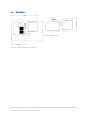
Front Plate View of the VSR
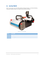
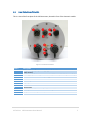
This is a view of the front plate of the VSR instrument, located in front of the electronic module.
Figure 3 - Instrument Front Plate
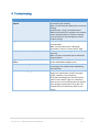
Item #
1
2
3
4
5
6
7
8
9
10
11
Description
24V power input (from power supply provided with instrument or external
power source)
Auxiliary power for instrument accessories (cold source, blackbody controller)
Reset switch for network factory settings
Green “Powered On” LED
Blue “Ready” LED
On/Off push button switch
USB connector for external USB accessories
GPS Antenna
Remote start switch to control local data acquisition
7 Amps fuse
Ethernet connection for network access
LR Tech Inc. VSR Instrument User Manual
4