1
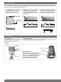
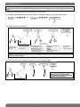
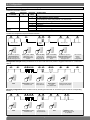
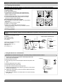
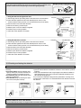
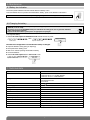
1. Introduction
The infrared detector is used for protection inside buildings. Intruders are detected when the infrared radiation associated
with movement varies. The detector also detects freezing temperatures based on a thermostatic principle (a technical alarm
is triggered when the temperature drops below 5°C).
• 171-21X/175-21X: motion detector
(19 fields-of-view, 12 m, 90°) is
designed to protect rooms at risk
(lounge, main bedroom, etc.).
detection zone
(1st interruption)
• 172-21X: corridor detector (9 fieldsof-view, 22 m, 12°) is designed for
unavoidable passageways, and can
be placed facing the entry point to
be protected.
2,2m
2,2m
1
1
0
detection zone
(2nd interruption)
0
8
4
4
6
8
4
6
8
10 12 14 16 18 20 22
2
1
2
1
0
2
2
0
1
2
3
4
5
6
7
8
9
10 11 12
0
1
2
3
4
5
6
7
8
9 10 11 12
12 m
2,20
0
• 173-21X: curtain detector (9 fieldsof-view, 12 m, 8°) is designed for the
protection of large surfaces (plate
glass windows, garage doors, etc.).
5
10
15
20 22
10 12 m
2m
2. Preparation
2.1 Opening
2.2 Power supply
Open the detector casing by loosening
the screws using a cross-head
screwdriver.
Connect the lithium battery pack according to the arrow.
Test button
Detection
lens
Alignment arrow
Test LED
indicator
lamp behind
lens
Locking screw
Removable tab
Guarantee sticker
Remove the pre-cut part of the sticker
and stick it to the guarantee certificate in
the user manual supplied with the control
panel. If you are adding the siren to an
existing system, use the guarantee
sticker provided with this product.
2
171-21X
171-21X
3. Programming
IMPORTANT: during recognition programming, the product to be programmed for use with the control panel does not need to
be placed next to it. In fact, we recommend you place the product at a short distance from the control panel (at least 2 meters
away).
Programming enables the detector to be recognised by the control panel.
1. To programme the detector the control panel must be in installation mode. If it is not, ask the user to press:
then
master code
(0000 by default)
“beep, installation
mode”
engineer installer code
(1111 by default)
2. Programme the device as follows:
“detector X”
“group?”
“time delay?”
“beep, detector X,
group Y immediate
(or delayed
or combined)”
)))
))
then
Press and hold the “test”
button until the control
panel responds
to
* according to the
type of control panel
10 s max.
Press * then # on
the control panel
keypad
*
to
The control panel waits
for a group to be chosen
(from 1 to 8)*. Choose the
group by pressing the
corresponding numeral on the
control panel keypad
Choose the type of triggering:
0: immediate
1: delayed
2: combined
Use the control panel keypad
to select the type
The control panel
gives a voice
message to confirm
IMPORTANT: the control panel indicates there is an error by emitting 3 short beeps. When this happens programming
should be carried out again.
• Example: programming of 1st detector allocated to Gr. 2 with immediate triggering.
“detector 1”
“group?”
“time delay?”
“beep, detector
1, group 2,
immediate”
)))
))
IMPORTANT: the control panel indicates
there is an error by emitting 3 short
beeps. When this happens programming
should be carried out again.
then
10 s max.
3
4. Configuration
IMPORTANT: The casing must be open when configuring the detector.
• Detection parameter selection:
Choice
of function
Detection sensitivity
Parameter
n°
1
Parameter
value
1
2
Alarm level
4
Freeze detection
setting
7
1
2
3
4
1
3
Technical data
1st edge triggering: not recommended for detector 171-21X/175-21X
2nd edge triggering (factory setting):
recommended for interior using detector 171-21X/175-21X
Intrusion (factory setting)
Prealert
Deterrence
Warning
Disabled (factory setting)
Enabled
• Follow the configuration sequence described below:
about 10 sec.
To start the sequence
press and hold the
button until the LED
indicator lamp goes out
1, 4 or 7
about
5 sec.
1 to 4
Press 1, 4 or 7 times
depending on the
required parameter
number
Press and hold
until the LED
indicator lamp
briefly goes out
Press 1 to 4 times
depending on the
required parameter
value
about 10 sec.
about 2 sec.
To end the sequence
press and hold the button
until the LED indicator
lamp goes out
LED indicator
lamp lit =
correct
configuration
Configuration example: setting the detector for an alarm level when a full prealert is triggered: Parameter n° 4, Parameter
value 2.
4
Start
Press 4 times to select
the alarm level
2
Press once to
accept selection
Press 2 times
to select
the prealert level
Press and hold until the
LED goes out to finish
Checking configuration: check the alarm level by selecting the Parameter N° and checking the number of corresponding
flashes.
4
Start
Press 4 times to select
the alarm level
2
Press once to
accept selection
4
End
2 flashes confirm
that the device is set
for a prealert
5. Installing the detector
5.1 Choosing the best place
IMPORTANT: make sure there is a distance of at least 2 meters between each product, except between two detectors.
The motion detector must be placed:
• inside the building,
• 2.20 m above ground level
• at right angles to the entrances to be protected (interior
detection works best when the intruder walks across the
detector’s fields-of-view),
• directed towards the inside of the room to be protected,
• in such a way that the area it protects does not overlap
with that of another motion detector.
The motion detector must not be placed:
• in an area likely to receive direct sunlight or a very powerful
light source,
• opposite or above a source of heat,
• outside or in a breezy place,
• directly on to a metal wall or close to sources of
interference (electricity meters, etc.) or ventilation such as
air-conditioning grilles.
RIGHT
WRONG
RIGHT
WRONG
5.2 Fixing method
IMPORTANT: for reasons of security and to ensure long battery life, installation of the anti-tamper pin is compulsory. In case of
omission or incorrect insertion of the pin, the detector LED indicator lamp flashes continuously when the detector is fitted to its
bracket.
The detector can be fixed to a wall
in 3 ways:
• on a swivel bracket,
• flat against the wall,
• in a corner.
Order in which to assemble parts
Pin n° 1
There is an anti-tamper pin for each
type of fixing method:
• swivel bracket: pin n° 0,
• flat: pin n° 1,
• in a corner: n° 2.
Base
Swivel
Long screw
Back plate
Pin n° 2
Screw
+ tightening
washer
Selection of pins
Back plate cover
• Fixing the detector on a swivel bracket
IMPORTANT: for swivel bracket fixing, pin n° 0 is already factory-positioned inside the detector.
1. Hold the back plate against the wall in the desired position and
mark where to drill the holes.
2. Drill the holes in the wall.
3. Insert the long screw via the back plate and fasten the plate to the
wall.
4. Put the back plate cover in place.
5. Assemble both parts of the swivel.
6. Insert the mounted swivel into the long screw.
7. Position the base of the motion detector (a picture of a man shows
the top of the detector).
8. Tighten the screws lightly in order to be able to adjust the direction
of the motion detector.
9. Place the motion detector on its base and turn it so that it is facing
the right way.
5
Pictogram
Pozidriv 2 1
Pozidriv
Pin n° 0
for swivel bracket
fixing (factorymounted pin)
IMPORTANT: when fixing the movement detector at an angle or flat against the
wall, fix the label (provided in the sachet of accessories) on the reverse side of the
product in order to cover the opening to avoid insects getting through.
Si fixation en angle ou à plat contre un mur
For a fixing in a corner or flat against the wall
2
Si fixation en angle ou à plat contre un mur
For a fixing in a corner or flat against the wall
1
653563_A
• Fixing the detector flat against the wall
1. Drill through the two pre-drilling holes in the base of the motion detector.
2. Place the base against the wall in the desired place in order to mark
where to drill the holes (a picture of a man indicates the top of the base).
3. Drill the holes in the wall and fix the base.
4. Remove the factory-positioned pin.
5. Detach pin n° 1 from the selection supplied.
6. Position the pin in the right place.
7. Place the motion detector on its base.
Pictogram
• Fixing the detector in a corner
1. Drill through the two pre-drilling holes in the base of the detector.
2. Place the base against the wall in the desired place in order to mark
where to drill the holes (a picture of a man indicates the top of the base).
3. Drill the holes in the wall and fix the base.
4. Remove the factory-positioned pin.
5. Detach pin n° 2 from the selection supplied.
6. Position the pin in the right place.
7. Place the motion detector on its base.
Pictogram
Pre-drilled holes
2 fixing
screws
Pozidriv 1
Pin n° 1 for fixing
the detector flat
against the wall
Pre-drilled holes
2 fixing
screws
Pozidriv 1
90°
Pin n° 2 for fixing
the detector
in a corner
5.3 Directing and testing the detector
IMPORTANT: the control panel must be in installation mode to check the above.
The infrared detector has a test mode for
checking:
• the power supply: the LED indicator lamp
lights up when you press the test button to
confirm the battery is operating correctly,
• the detection area: the LED indicator lamp
lights up on detection,
• the radio link (see § on checking the radio
link in the control panel manual).
“beep, detector X,
group Y immediate
(or delayed
or combined)”
Checking the detection area:
• press on the test button: the detector switches to test mode for a period
of 90 sec.,
• walk across the detection area at right angles to the detector’s fields-ofview (see diagram): every time movement is detected the detector test
LED indicator lamp lights up.
If no movement is detected: change the way the detector is facing on its
swivel bracket, check there is no obstacle between the detection area and
the detector.
171-21X
175-21X
172-21X
173-21X
)))
))
IMPORTANT: at the end of the test period, the detector automatically switches back to normal operating mode:
• detector inhibited for 90 sec. after detection,
• the test LED indicator lamp is no longer lit when movement is detected.
6
6. Maintenance
6.1 Battery low indication
The control panel indicates when the infrared detector’s battery is low.
To check whether there is a problem with the detector battery, press on the detector’s test button.
IMPORTANT: if the test LED indicator lamp no longer lights up, the lithium battery should be replaced.
6.2 Changing the battery
• The lithium battery pack must be replaced by the same type of pack with the same technical characteristics
(BATLi25, 2 x 3.6 V – 2 Ah).
• We advise you to use the DAITEM BatLi25 pack available in the catalogue in order to guarantee individual
safety and equipment reliability.
• Dispose of the waste lithium power pack in an appropriate recycling bin.
Li
To change the battery:
1. Switch the control panel to installation mode and ask the user to press:
then
master code
“beep, installation
mode”
engineer installer code
The detector’s configuration is saved when the battery is changed.
2. Open the detector casing (see § on Opening).
3. Unclip the lithium battery pack.
IMPORTANT: Pull on the tab to remove the lithium battery.
4. Wait 2 min. before replacing the flat lithium battery.
5. Close the detector.
6. Switch the control panel back to user mode. Press:
engineer installer code
“beep, date,
time, off”
7. Technical data
Specifications
Infrared detection
Fixing methods
Use
Power supply
Battery life
Average humidity rate
Radio links
Test button
LED indicator lamp
Operating temperature
Protection mechanism
Degrees of mechanical protection
Dimensions without swivel bracket
Weight
Infrared motion detector
• 171-21X/175-21X: 12 m, 90°, motion detector
• 172-21X: 22 m, 12°, corridor detector
• 173-21X: 12 m, 8°, curtain detector
• on a swivel bracket
• flat against the wall
• in a corner
inside
2 x 3.6 V - 2 Ah BatLi25 lithium battery
5 years in normal conditions of use
5% to 75% without condensation at 25°C
TwinBand® 400/800 MHz
battery and detection
1
-10° C to +55° C
against opening and removal (unless swivel bracket mounted)
IP 31/ IK 04
58 x 102 x 57 mm
115 g (with battery, swivel bracket and base)
7
DECLARATION OF CONFORMITY
GB
Manufacturer: Hager Security SAS
12
Address: F-38926 Crolles Cedex - France
Product type: Motion detector
Trade mark: Daitem
We declare under our sole responsibility that the products to which this declaration relates
are thus compliant with the essential requirements of the following European Directives:
• R&TTE Directive: 99/5/CE
• Low Voltage Directive: 2006/95/CE
• ROHS Directive: 2002/95/CE
in compliance with the following harmonised European Standards:
Products code
171-21X 172-21X 173-21X 175-21X
EN 300 220-2 V2.1.2
X
X
X
X
X
X
X
X
X
X
X
X
X
X
X
X
EN 300 330-2 V1.3.1
EN 50130-4 (95) + A1 (98) + A2 (2002)
EN 55022 & 55024 (2002)
EN 60950 (2006)
EN 301 489-1 V1.8.1
These products can be used in all EU, EEA Countries and Switzerland.
Crolles, 31.08.2012
Signature:
Patrick Bernard
Research & Development Manager
805153/A - 10.2012
Non-binding document, subject to modification without notice.