1
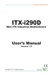
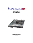
EXPC-1319 Series Hardware Manual Second Edition, January 2014 www.moxa.com/product © 2014 Moxa Inc. All rights reserved. Reproduction without permission is prohibited. EXPC-1319 Series Hardware Manual The software described in this manual is furnished under a license agreement and may be used only in accordance with the terms of that agreement. Copyright Notice Copyright ©2014 Moxa Inc. All rights reserved. Reproduction without permission is prohibited. Trademarks The MOXA logo is a registered trademark of Moxa Inc. All other trademarks or registered marks in this manual belong to their respective manufacturers. Disclaimer Information in this document is subject to change without notice and does not represent a commitment on the part of Moxa. Moxa provides this document as is, without warranty of any kind, either expressed or implied, including, but not limited to, its particular purpose. Moxa reserves the right to make improvements and/or changes to this manual, or to the products and/or the programs described in this manual, at any time. Information provided in this manual is intended to be accurate and reliable. However, Moxa assumes no responsibility for its use, or for any infringements on the rights of third parties that may result from its use. This product might include unintentional technical or typographical errors. Changes are periodically made to the information herein to correct such errors, and these changes are incorporated into new editions of the publication. Technical Support Contact Information www.moxa.com/support Moxa Americas Moxa China (Shanghai office) Toll-free: 1-888-669-2872 Toll-free: 800-820-5036 Tel: +1-714-528-6777 Tel: +86-21-5258-9955 Fax: +1-714-528-6778 Fax: +86-21-5258-5505 Moxa Europe Moxa Asia-Pacific Tel: +49-89-3 70 03 99-0 Tel: +886-2-8919-1230 Fax: +49-89-3 70 03 99-99 Fax: +886-2-8919-1231 Table of Contents 1. Introduction ...................................................................................................................................... 1-1 Overview ........................................................................................................................................... 1-2 Model Descriptions and Package Checklist .............................................................................................. 1-2 Appearance........................................................................................................................................ 1-3 Features ............................................................................................................................................ 1-4 Hardware Specifications ...................................................................................................................... 1-5 LED Indicators and Buttons .................................................................................................................. 1-7 LCD Panel and Touch screen ................................................................................................................ 1-7 Moxa Intelligent Heating Solution ......................................................................................................... 1-8 2. Hardware Installation ....................................................................................................................... 2-1 Placement Options .............................................................................................................................. 2-2 Desktop ..................................................................................................................................... 2-2 Mounting .................................................................................................................................... 2-2 Wall Mounting ............................................................................................................................. 2-2 Other Mounting Solutions .................................................................................................................... 2-3 Yoke Mounting ............................................................................................................................ 2-3 Panel Mounting ........................................................................................................................... 2-4 VESA Mounting ........................................................................................................................... 2-5 Wiring Requirements ........................................................................................................................... 2-5 Connecting the Power Supply ............................................................................................................... 2-6 Connecting the Interfaces .................................................................................................................... 2-6 Connecting to a Display ....................................................................................................................... 2-7 Connecting USB Devices ...................................................................................................................... 2-7 Connecting Serial Devices .................................................................................................................... 2-8 Connecting LAN Ports .......................................................................................................................... 2-9 Replacing the SSD ............................................................................................................................ 2-11 Installing the CompactFlash Card ........................................................................................................ 2-11 3. Touch Screen Calibration .................................................................................................................. 3-1 Calibrating the Touch Screen................................................................................................................ 3-3 Standard Calibration .................................................................................................................... 3-3 Advanced Calibration ................................................................................................................... 3-3 PenMount Calibration Utility Parameters ................................................................................................ 3-4 Turn off EEPROM Storage ............................................................................................................. 3-4 Touch Screen Cursor Settings ....................................................................................................... 3-4 Edge Compensation ..................................................................................................................... 3-5 4. BIOS Setup........................................................................................................................................ 4-1 Entering the BIOS Setup Utility ............................................................................................................ 4-2 BIOS Main Page.................................................................................................................................. 4-2 Modifying BIOS Settings ...................................................................................................................... 4-3 Advanced Settings ....................................................................................................................... 4-3 Security Settings ......................................................................................................................... 4-9 Power Settings .......................................................................................................................... 4-10 Boot Settings ............................................................................................................................ 4-12 Exit Settings ............................................................................................................................. 4-13 Upgrading the BIOS .......................................................................................................................... 4-15 A. Safety Installation Instructions ........................................................................................................ A-1 B. Statement of Regulatory Approval .................................................................................................... B-1 1 1. Introduction Thank you for purchasing the Moxa EXPC-1319 series x86 industrial panel computer. This manual introduces the hardware installation, connector interfaces, and BIOS setup of the EXPC-1319. For software configuration and management, please refer to the user’s manual for your operating system. The following topics are covered in this chapter: Overview Model Descriptions and Package Checklist Appearance Features Hardware Specifications LED Indicators and Buttons LCD Panel and Touch screen Moxa Intelligent Heating Solution EXPC-1319 Series Hardware Introduction Overview The EXPC-1319 panel computers are fanless, durable devices made for both indoor and outdoor hazardous environments. The EXPC-1319 series features the dual core Intel Atom D525 1.8 GHz processor, with up to 4 GB of memory available to deliver high performance processing. The EXPC-1319 is Zone 2 certified, and comes with two electrically isolated, software-selectable RS-232/422/485 serial ports alongside two Gigabit LAN ports, providing reliable serial and high speed Ethernet LAN transmissions with full network redundancy. The EXPC-1319 computers come with a patented, fanless, streamlined enclosure designed for highly efficient heat dissipation, making this one of the most reliable industrial platforms available for harsh, hot outdoors environments like oil and gas fields or drilling platforms. In addition, EXPC-1319 computers come with an expanded set of self-health diagnostics that communicate over SNMP and may also be ordered with Moxa’s Intelligent Heating Solution (IHS), a heating utility for use in extremely low temperature (-40°C) environments. Finally, these computers feature capacitive touch screen controls with glass-film- glass bonding, making them scratch- and glare-resistant and easy to read even during the peak daylight hours. Model Descriptions and Package Checklist The EXPC-1319 Series includes the following models: EXPC-1319-STS-W7E: Fanless, industrial-rugged Zone 2 19-inch 1000 nits LCD panel computer, single point touch screen, IP66, dual core Atom D525 1.8 GHz CPU, -20 to 60°C operating temperature EXPC-1319-STS-IHS-W7E: Fanless industrial-rugged Zone 2 19-inch 1000 nits LCD panel computer, single point touch screen, IP66, dual core Atom D525 1.8 GHz CPU, -40 to 60°C operating temperature, with Intelligent Heating Solution (IHS) EXPC-1319-MTS-W7E: Fanless industrial-rugged zone 2 19-inch 1000 nits LCD panel computer, multi point touch screen, IP66, dual core Atom D525 1.8 GHz CPU, -20 to 60°C operating temperature (available on request) EXPC-1319-MTS-IHS-W7E: Fanless industrial-rugged Zone 2 19-inch 1000 nits LCD panel computer, multi point touch screen, IP66, dual core Atom D525 1.8 GHz CPU, -40 to 60°C operating temperature, with Intelligent Heating Solution (IHS) (available on request) Each model is shipped with following standard items: 1 EXPC-1319 panel computer Quick Installation Guide Documentation & Software DVD Ethernet Cable: RJ45 to RJ45 cross-over cable, 100 cm Waterproof USB connector pack x 2 Waterproof DB9 connector pack x 2 Waterproof LAN connector pack x 2 Waterproof power connector pack x 1 Wall mounting kit Warranty statement 1-2 EXPC-1319 Series Hardware Introduction Appearance Front and Side Views Rear and Bottom Views 1-3 EXPC-1319 Series Hardware Introduction Dimensions Features Zone 2 certified component for panel mounting in hazardous area applications High performance dual core Intel Atom D525 1.8GHz platform with low power consumption 19-inch scratch-resistant anti-glare 1000 nits LCD panel Self-health diagnostics software package for remote predictive maintenance -40 to 60°C wide operating temperature (with built-in Intelligent Heater) Totally sealed IP66 / NEMA 4X panel computer (not for using in hazardous environments) Fanless, streamlined enclosure for highly efficient heat dissipation Touch screen control button to enable/disable touch screen Optional WLAN, 100M fiber optical interface 1-4 EXPC-1319 Series Hardware Introduction Hardware Specifications Computer CPU: Intel dual core Atom D525 1.8 GHz processor OS: Windows 7 for embedded systems System Chipset: Intel Pineview-D+ ICH8M BIOS: 16-Mbit Flash BIOS SPI type with ACPI Graphics Controller: Integrated Intel GMA3150 graphics controller Video Output: VGA output, waterproof DB15 (female) connector System Memory: 4 GB capacity, 2 GB pre-installed: 2 slots of 2 GB DDR3-800 SO-DIMM SDRAM Automatic Reboot Trigger: Built-in software programmable watchdog timer for system resets, configurable from 1 to 255 second timeout intervals Expansion Bus: 1 PCI-104 slot, 1 mini PCIe socket USB: 2 USB 2.0 hosts, waterproof circular type A connector KB/MS: PS/2 keyboard/mouse interface (Y-type cable) with waterproof connector (optional, not for using in hazardous environments) Storage Storage Expansion: • On-board CompactFlash socket x 1 • One extra on-board SATA interface, supporting configurable RAID 0/1 Storage Support: Removable 32 GB industrial grade SSD (operating temperature: -40 to 85°C) to store OS, ; supports up to 256 GB Display Panel Size: 19-inch SXGA, 1000 nits LED backlit LCD Aspect Ratio: 5:4 Response Time: 5 ms Contrast Ratio: 1000:1 Viewing Angles: • Horizontal: 170° (left to right) • Vertical: 160° (up to down) Max Colors: 16.7 M colors Graphics Controller: Integrated Intel GMA3150 graphics controller Video Output: VGA output, waterproof DB15 (female) connector Resolution: • VGA: 640 x 480 • SVGA: 800 x 600 • XGA: 1024 x 768 • SXGA: 1280 x 1024 Touch screen EXPC-1319-STS: Resistive single point glass-film-glass EXPC-1319-MTS: Capacitive multi point (available on request, not for using in hazardous environments) Note: All EXPC-1319 touch screens are scratch resistant and anti-glare, suitable for use outdoors around heavy equipment. Ethernet Interface Hardware Interface: Waterproof RJ45 connector LAN: 2 auto-sensing 10/100/1000 Mbps ports Optical Fiber Interface: 2 multimode 100M fiber optic ports with waterproof Q-ODC connector (available on request) WLAN: 1 802.11b/g/n interface (available on request) Magnetic Isolation Protection: 1.5 kV built-in Serial Interface Serial Standards: 2 RS-232/422/485 ports, software-selectable Connector Type: Waterproof DB9 (male) 1-5 EXPC-1319 Series Hardware Introduction Baudrate: Up to 38,400 bps Isolation Protection: 2 kV Serial Communication Parameters Data Bits: 5, 6, 7, 8 Stop Bits: 1, 1.5, 2 Parity: None, Even, Odd, Space, Mark Flow Control: RTS/CTS, XON/XOFF, ADDC® (automatic data direction control) for RS-485 Serial Signals RS-232: TxD, RxD, DTR, DSR, RTS, CTS, DCD, GND RS-422: TxD+, TxD-, RxD+, RxD-, GND RS-485-4w: TxD+, TxD-, RxD+, RxD-, GND RS-485-2w: Data+, Data-, GND LEDs and Buttons LEDs: Power (on/off), heater (on/off), storage (blinking/off), LAN port communication x 2 (on/off), fiber communication (reserved) Control Buttons: System on/off, brightness adjustment x 2, touch screen on/off, programmable "Fn" button Physical Characteristics Housing: Aluminum Weight: • 10.7 kg (without Intelligent Heating Solution) • 11.9 kg (with Intelligent Heating Solution) Dimensions: 483 x 408 x 99 mm (19.02 x 16.06 x 3.90 in) Mounting: Mounting holes for VESA 75/100, yoke mounting, and panel mounting Environmental Limits Operating Temperature: • Without Intelligent Heating Solution: -20 to 60°C (-4 to 140°F) • With Intelligent Heating Solution: -40 to 60°C (-40 to 140°F) Storage Temperature: -40 to 80°C (-40 to 176°F) Ambient Relative Humidity: 5 to 95% (non-condensing) Anti-Vibration: 2 g rms, 5-500 Hz frequency, compliant with IEC 60068-2-6 standard Anti-Shock: 20 g, half sine wave under system operating, 11 ms duration, compliant with IEC 60068-2-27 standard Power Requirements Input Voltage: • Typical 24 VDC • External 100 to 240 VAC isolated power supply unit (available on request, not for using in hazardous environments) Connector: M12, customizable Power Consumption: • Without Intelligent Heating Solution: 60 W • With Intelligent Heating Solution: 120 W Standards and Certifications Hazardous Environments: UL Class 1 Division 2, ATEX/IECEx Zone 2 certified component EMC: EN 55022 Class B, EN 55024-4-2, EN 55024-4-3, EN 55024-4-4, FCC Part 15 Subpart B Class A Mechanical: IP66, NEMA 4X Green Product: RoHS, cRoHS, WEEE Warranty Warranty Period: 3 years for computer system, 1 year for LCD panel Details: See www.moxa.com/warranty 1-6 EXPC-1319 Series Hardware Introduction LED Indicators and Buttons The EXPC-1319 comes with six LED indicators and five control buttons on the bottom of the front panel. LED Indicators Power Heater Function On Power is on. Off Power is off. On Heater is working. (Note that this function will be enabled when below -20˚C) Off Heater is not working. Storage Blinking Storage (SSD or CF) is accessing. Off Storage (SSD and CF) is not accessing. Fiber Reserved for optional function LAN1 & LAN 2 On Network is transmitting or receiving data. Off Network is not transmitting or receiving data. Control Buttons Function Power Press to turn on the computer. Press again to turn off the computer. Brightness Press + button to increase the brightness of the panel. Press – button to decrease the brightness of the panel. Function Customizable function key, can be configured by the utility. The default value will enable a virtual keyboard function. Refer to Software User’s Manual for configuration details. Touch screen Touch to enable the touch screen function (default). Touch again to disable. LCD Panel and Touch screen The EXPC-1319 comes with 1000 nits TFT LCD panel with touch screen bonding. The 1000 nits TFT LCD panel means the panel’s brightness at its central point is 1000 cd/m2. Due to the characteristics of liquid crystal in TFT LCD panels, even though the EXPC-1319 will work properly between -20 and 60˚C (-40 to 60˚C with Intelligent Heating Solution), to extend the panel’s life Moxa recommends maintaining the working temperature between 0 and 50˚C whenever possible. Some areas on the LCD panel might distort some colors to black at extremely high temperatures, or respond sluggishly at extremely low temperatures. The touch screen used on the EXPC-1319 includes hardened resistive glass-film-glass single point touch screen (STS) or a capacitive type multipoint touch screen (MTS). Different touch screen technologies allow different 1-7 EXPC-1319 Series Hardware Introduction light transmission rates to decrease the brightness of LCD panel. Usually the light transmission rate of resistive type touch screens is around 80%, while for capacitive types it is around 85% to 90%. Please note that the screen is composed of hardened, scratch-resistant glass, and its anti-glare coating can still be scratched using any abrasive with Mohs rating greater than 6. Please note that the capacitive type multipoint touch screen (MTS) model cannot be used in the hazardous environments. Notice: Please calibrate your touch screen every time you reboot the system to ensure the touch screen works properly. To review touch screen calibration, please refer to the Touch screen Calibration section in Chapter 4 of the EXPC-1319 Windows Embedded Standard 7 User’s Manual. Moxa Intelligent Heating Solution The EXPC-1319 may be ordered with Moxa’s patented Intelligent Heating Solution, to extend the effective range of the platform’s operating temperature, with the caveats below. EXPC-1319 computers equipped with IHS feature the heating solution on the display panel. The Intelligent Heating Solution will automatically initiate once the ambient temperature drops below -20˚C. It takes about 40 to 50 minutes for the Intelligent Heating Solution to warm up the display panel. Once IHS has completed the heating cycle, the LED indicator for the Heater will turn off. Until the warming up cycle is completed, the display may be distorted or otherwise function poorly. Moxa Intelligent Heating Solution remains (minimally) powered up and operating even after the computer has been taken offline. This is to ensure its automated response when ambient temperatures drop below 0˚C. NOTE IHS may only be turned off by disconnecting the power supply. IHS requires a 120 W power supply. To ensure that the IHS has been completely stopped, make sure to remove the power source after shutting down the EXPC-1319. 1-8 2 2. Hardware Installation The EXPC-1319 Series of panel computers are compact and rugged, making them suitable for any industrial application that requires EMC Level 4 compliance. The LED indicators allow users to monitor performance and identify trouble spots quickly, and multiple ports are provided for connecting a variety of different devices. The EXPC-1319 hardware platform is stable, reliable, and easy to maintain, allowing you to spend your time on application development rather than troubleshooting networking bugs. This chapter describes the hardware installation and interfaces of EXPC-1319 panel computers. The following topics are covered in this chapter: Placement Options Desktop Mounting Wall Mounting Other Mounting Solutions Yoke Mounting Panel Mounting VESA Mounting Wiring Requirements Connecting the Power Supply Connecting the Interfaces Connecting to a Display Connecting USB Devices Connecting Serial Devices Connecting LAN Ports Replacing the SSD Installing the CompactFlash Card EXPC-1319 Series Hardware Hardware Installation Placement Options ATTENTION! For maximum safety, at least two persons should work together to lift, place, and fasten the computer to its mounting point. Before you lift or move the computer, first verify both it and any power to the system is turned off. In addition, make sure you have prepared the correct screws for a wall mounting. Desktop Place your EXPC-1319 on a clean, flat, well-ventilated desktop. For better ventilation, leave some space between the EXPC-1319 and other equipment. Do not place equipment or objects on top of the EXPC-1319, as this might damage the computer’s internal components. Mounting The EXPC-1319 comes with a variety of mounting methods for different field sites. Before mounting, refer to the following figure for the dimensions of the screw holes used for different mounting methods. Wall Mounting The EXPC-1319 comes with a wall mounting kit. Follow these steps to mount the EXPC-1319 on a wall: Step 1: Use screws to attach the mounting ears to the back of the computer. Each mounting ear requires three screws. 2-2 EXPC-1319 Series Hardware Hardware Installation Step2: Fasten the computer to the wall using three screws per ear. NOTE To make sure the panel computer will be securely installed on a wall, we suggest you to use M5 screws of a suitable length to guarantee the computer remains securely fastened to the mounting point. The screw holes penetrate 8 mm into the computer’s case. When choosing screws for installation, remember to account for the thickness of the mounting surface. Other Mounting Solutions The EXPC-1319 computers have reserved various mounting holes for users to mount the computer with different solutions, including yoke mounting, panel mounting, and VESA mounting. See the following section for detailed descriptions. Yoke Mounting The EXPC-1319 comes with six screw holes for a yoke mount. These screws holes are the same size as those for the wall mounting. Place the panel onto the mounting plate, fasten the computer using these holes. 2-3 EXPC-1319 Series Hardware NOTE Hardware Installation To make sure the panel computer will be securely installed on the yoke, use M4 screws. The screw holes penetrate 8 mm into the computer’s case. When choosing screws for installation, remember to account for the thickness of the mounting surface. Refer to Appendix B: Statement of Regulatory Approval for the technical details regarding regulation Class 1 Div. 2 devices. Panel Mounting Follow these steps to install the EXPC-1319 on a panel cabinet. 1. Place the gasket between the EXPC-1319 and the enclosure, and use eight M6 screws to penetrate the enclosure and gasket, so that the gasket can be securely fasten on two sides of the panel mounting holes on the back of the EXPC-1319. NOTE To make sure the panel computer will remain securely installed in the cabinet, use M6 screws of a suitable length. The screw holes penetrate 6 mm into the computer’s case. When choosing screws for installation, remember to account for the thickness of the mounting surface. 2. Install the mounting brackets from inner part of the computer, and use M4 screws to fasten the brackets. Four screws are required per side. NOTE For the installation in hazardous environments, refer to Explosion Hazard section in Appendix B. 2-4 EXPC-1319 Series Hardware Hardware Installation VESA Mounting The EXPC-1319 comes with two sets of holes reserved for VESA mounts (FDMI): VESA 100 and VESA 75. Refer to the following figures for the specific locations of the VESA mounting screw holes. NOTE To make sure the panel computer will be securely installed on a wall, we suggest you to use the screws with the specifications of M4. The screw holes penetrate 6 mm into the computer’s case. When choosing screws for installation, remember to account for the thickness of the mounting surface. Refer to Appendix B: Statement of Regulatory Approval for the technical details regarding regulation Class 1 Div. 2 devices. Wiring Requirements The following common safety precautions should be observed before installing any electronic device: • Strive to use separate, non-intersecting paths to route power and networking wires. If power wiring and device wiring paths must cross, make sure the wires are perpendicular at the intersection point. • Keep the wires separated according to interface. The rule of thumb is that wiring that shares similar • Do not bundle input wiring with output wiring. Keep them separate. • When necessary, it is strongly advised that you label wiring to all devices in the system. electrical characteristics may be bundled together. ATTENTION Do not run signal or communication wiring and power wiring in the same conduit. To avoid interference, wires with different signal characteristics (i.e., different interfaces) should be routed separately. 2-5 EXPC-1319 Series Hardware Hardware Installation ATTENTION Safety First! Be sure to disconnect the power cord before installing and/or wiring your device. Caution! High Electrical Current! Verify the maximum possible current for each wire gauge, especially for the power cords. Observe all electrical codes dictating the maximum current allowable for each wire gauge. If the current goes above the maximum ratings (120 W), the wiring could overheat, causing serious damage to your equipment. Caution! High Temperatures! Be careful when handling the unit. When the unit is plugged in, the internal components generate a lot of heat which may leave the outer casing too hot to touch. Connecting the Power Supply The power connector is located at the far left of the bottom panel. When wiring the machine for power, refer to the following figure for the pinout of the M12 power connector. Please take care to guarantee your power cable uses the correct pinout. When power has been connected, press the power button on the front panel to turn on the computer. Connecting the Interfaces The EXPC-1319 comes with various interfaces located on the bottom panel. All of these connectors have been shipped with protective caps and tethers. If you wish to detach the tethers from the computer the screws securing them to the rear panel will need to be removed. To keep water out of the enclosure and preserve the life of the EXPC-1319, leave the protective caps in place (with their tethers) whenever the hardware interfaces are not used. 2-6 EXPC-1319 Series Hardware Hardware Installation Connecting to a Display The EXPC-1319 comes with a 19-inch LED-backlit LCD display. Because the configuration of a 2nd or alternate display may be required, the EXPC-1319 also comes with a VGA interface on its bottom panel. The VGA hardware interface is a standard D-Sub 15-pin female connector; to ensure that the monitor image remains clear, be sure to tighten the monitor cable after connecting it to the EXPC-1319 computer. The pin assignments are shown below. WARNING When the external VGA display is not in use, make sure that the protective cap and the tether tail have been securely fastened so that the waterproof function can work well. Please note that when reinstalling the protective cap, it must be fully tightened to insure the unit is sealed correctly to meet the IP66 enclosure rating. You may refer to Appendix B: Statement of Regulatory Approval for the technical details regarding regulation Class 1 Div. 2 devices. DB-15 Female VGA Connector Pin No. Signal Definition Pin No. Signal Definition 1 Red 9 VCC 2 Green 10 GND 3 Blue 11 NC 4 NC 12 DDC2B Data 5 GND 13 HSYNC 6 GND 14 VSYNC 7 GND 15 DDC2B Clock 8 GND Connecting USB Devices The EXPC-1319 embedded computer has two USB 2.0 ports on the bottom panel. All of the ports are UHCI, Rev 2.0 compliant and support Plug & Play and hot swapping. These ports can be used to connect USB devices such as a keyboard, mouse, USB flash disk, and USB CD-ROM. In addition, both USB ports support system boot up, which can be activated by modifying the BIOS settings. BIOS configuration is described in detail in Chapter 4: BIOS Setup. Follow the steps below to wire up the USB connectors. Step 1: Disassemble the waterproof USB connector into four parts. Thread the end of the wire you intend to connect through parts 4, 3, and 2, in that order. Step 2: Connect the wires to the USB head according to the pinout shown in the table below. Step 3: When finished, assemble the USB parts, and connect the USB connector on the bottom panel of the EXPC-1319. Make sure the connector 2-7 EXPC-1319 Series Hardware Hardware Installation has been securely fastened to ensure the waterproof function. Pin Number Assignment 1 VCC 2 DATA- 3 DATA+ 4 Ground WARNING To keep the EXPC-1319 within the IP66 rating’s waterproof specifications, when the USB ports are not in use operators must replace the protective caps and the tethers, and make sure they have been properly fastened. Please note that when reinstalling the protective caps they must be tightened to 136 N-cm (12 in-lbs) to ensure the unit is sealed to IP66 specifications. In addition, because of the danger posed by the maximum 5V @ 500 mA power supply of standard USB ports, care must be taken to protect the EXPC-1319 from power accidents in damp environments. To guarantee safety from severe electrical shoks or electrocution, in damp conditions users should disconnect the entire computer from its power source before connecting or disconnecting any USB devices. You may refer to Appendix B: Statement of Regulatory Approval for the technical details regarding regulation Class 1 Div. 2 devices. Connecting Serial Devices The EXPC-1319 comes with two RS-232/422/485 serial ports with DB9 male connector. Step 1: Disassemble the waterproof DB9 connector into four parts. Step 2: Connect the serial signal wires with the correct pin definition. See the following figure and table. Step 3: When finished, assemble the DB connector parts, and connect to the DB9 connector on the bottom panel of the EXPC-1319. Make sure the connector has been securely fastened to ensure the waterproof function. The pin assignments for RS-232/422/485 serial ports are shown in the following table: DB-9 Male Port RS-232/422/485 Pinouts Pin RS-232 RS-422 1 DCD TxDA(-) TxDA(-) – 2 RxD TxDB(+) TxDB(+) – 3 TxD RxDB(+) RxDB(+) DataB(+) 4 DTR RxDA(-) RxDA(-) DataA(-) 5 GND GND GND GND 6 DSR – – – 7 RTS – – – 8 CTS – – – 2-8 RS-485-4W RS-485-2W EXPC-1319 Series Hardware Hardware Installation WARNING When the serial ports are not in use, make sure that the protective caps and the tethers have been securely fastened to keep water from entering the enclosure. Please note that when reinstalling the protective caps the screws which keep them in place must be tightened to 136 N-cm (12 in-lbs) to ensure the unit is sealed to IP66 specifications. You may refer to Appendix B: Statement of Regulatory Approval for the technical details regarding regulation Class 1 Div. 2 devices. Connecting LAN Ports The EXPC-1319 has two 10/100/1000 Mbps LAN ports. These LAN ports come with waterproof RJ45 connectors. Follow the steps below to connect the LAN ports. By default, the LAN ports use DHCP addressing to assign network IP addresses. For detailed network configuration, please refer to the EXPC-1319 Win 7 Embedded Software Manual. Step 1: Disassemble the waterproof RJ45 LAN connector into four parts. Step 2: Users need to connect the twisted pair wire to the correct pinouts. For pinouts, refer to the figure and table just below. Step 3: Pass LAN twisted pair through parts 4, 3, and 2, in that order, then connect it to the RJ45 head. When finished, reassemble the LAN parts, and insert the RJ45 head into the bottom panel of the EXPC-1319. Make sure the connector is securely fastened to ensure full water resistance. Pin No. 100 Mbps Signal 1000 Mbps Signal 1 ETx+ TRD (0)+ 2 ETx- TRD (0)- 3 ERx+ TRD (1)+ 4 -- TRD (2)+ 5 -- TRD (2)- 6 ERx- TRD (1)- 7 -- TRD (3)+ 8 -- TRD (3)- 2-9 EXPC-1319 Series Hardware Hardware Installation WARNING When the Ethernet LAN ports are not in use, make sure that the protective caps and tethers have been securely fastened to keep water from entering the enclosure. Please note that when reinstalling the protective caps they must be tightened to 136 N-cm (12 in-lbs) to ensure the unit is sealed to IP66 specifications. You may refer to Appendix B: Statement of Regulatory Approval for the technical details regarding regulation Class 1 Div. 2 devices. 2-10 EXPC-1319 Series Hardware Hardware Installation Replacing the SSD The EXPC-1319 comes with a removable 32 GB industrial SSD that can be upgraded to a maximum of 256 GB. To replace the SSD, follow these steps. 1. Remove the SSD cover, located on the left side of the computer (shown at right). 2. Remove the SSD by pulling out the plastic plate (shown at left). 3. Remove the screws on two sides of the SSD, and then remove the plastic plate. 4. Place the plastic plate on the new SSD, and fasten the screws on two sides of the SSD. When finished, insert the SSD into the socket (shown at left) 5. Set the SSD cover in place and fasten it using the original four screws. NOTE Please note that the operating system is stored on the SSD. If you replace this SSD with a new model you will may perform a system recovery procedure to re-install the operating system on the new SSD. For details about this procedure, please refer to the System Recovery chapter in either the EXPC-1319 Win 7 Embedded (Chapter 9), or EXPC-1319 Win Linux (Chapter 5) software manuals,. Installing the CompactFlash Card The EXPC-1319 comes with an onboard CompactFlash socket located just beside the SSD socket. Follow these steps to install. 1. Remove the SSD cover, located on the left side of the computer (shown at right). 2. The CompactFlash socket is located beside the SSD socket (shown at left). 2-11 EXPC-1319 Series Hardware 3. Hardware Installation Carefully insert the CompactFlash card into the socket, hardware interface first (shown at right). To remove the card, you may need to use a screwdriver or other long, slender tool. 4. NOTE When finished, place the cover back and fasten the screws. Please note that the SSD/CompactFlash cover comes with rubber pads fastened to the back plate, to help secure the SSD and CF cards. These pads also help reduce vibration and assist in keeping the SSD and CF slots waterproof, so take care to preserve them and follow suggested procedures when securing the cover. 2-12 3 3. Touch Screen Calibration Calibrating the Touch Screen Standard Calibration Advanced Calibration PenMount Calibration Utility Parameters Turn off EEPROM Storage Touch Screen Cursor Settings Edge Compensation EXPC-1319 Series Hardware Hardware Installation 2-2 EXPC-1319 Series Hardware Hardware Installation Calibrating the Touch Screen This chapter describes the calibration process for the EXPC-1319 touch panel. First, Open the PenMount control panel. This may be found under the Windows 7 Start Menu, in the Programs list in the PenMount Windows Universal Driver(WHQL) folder. From the PenMount folder, navigate to the Utility folder and open the PenMount Control Panel. Next, the PenMount Control Panel should appear as in the screen shot to the right, with the Device tab as its default display. Double-click on the device you want to calibrate, or select the device and click Configure. If you do not see your device offered on the menu, click Refresh to refresh the list. The final preparatory step is to choose what sort of calibration you want. Most will choose Standard Calibration, which is a basic touch screen calibration using five reference points. For most situations, a standard calibration should be adequate. As the touch screen ages, users will find that the standard calibration is not adequate for re-establishing screen accuracy and precision. If problems are still encountered following a standard calibration, you may choose Advanced Calibration to calibrate the touch screen to a greater number of reference points. Standard Calibration For a standard five point calibration, five spots will appear one after another on the display. Use your finger or stylus to touch the five points in order. After you have completed the sequence, hit ESC on your keyboard to save the result and exit the calibration process. Advanced Calibration An advanced calibration uses 9, 16, or 25 points to calibrate touch panel linearity; select the number of reference points from the drop-down menu offered on the calibration utility main dialog. You may also instruct the calibration utility to plot detailed calibration data onto a graph. For more information about the data graph, see the next section, Calibration Data Graph. Just as with the standard calibration, to complete the calibration use your finger or stylus to touch the points in order, as they appear. After you have completed the sequence, hit ESC on your keyboard to save the result and exit the calibration process. 2-3 EXPC-1319 Series Hardware Hardware Installation Advanced Calibration: Calibration Data Graph If you performed an advanced calibration and ticked the Plot Calibration Data selection, then after you complete an advanced calibration the calibration utility will provide you with a graph comparing ideal panel linearity as assumed by the PenMount utility (the black lines) plotted against the approximate linearity derived by the PenMount utility from the user calibration process (the blue lines). Please note that this function is mainly used by the panel manufacturer for troubleshooting. To exit the graph, simply touch the screen. If you feel you have discovered problems with calibration that you cannot solve using the PenMount calibration utility, please contact Moxa’s Embedded Computing Technical Support staff. PenMount Calibration Utility Parameters Turn off EEPROM Storage Ticking this box disables the storage of calibration data in the permanent EEPROM screen controller; instead, the calibration data is saved to the system drive. If you turn off EEPROM storage, the value will be stored and available from one restart to the next, but the changes will be lost should you perform a system software recovery, forcing you perform a touch panel recalibration. Touch Screen Cursor Settings The Settings tab allows for configuration of four main touch screen cursor features: cursor behavior (mouse emulation or stylus mode), a beep that sounds when contact with the touch screen is made or broken, a cursor stabilizer, and press-and-hold in place of right clicking. The top drop-down may only be set to mouse emulation. No other modes are available. 2-4 EXPC-1319 Series Hardware Hardware Installation Beep mode allows you to configure a beeping sound to play whenever contact is made (or broken) with the screen. The beep may be configured for tone, frequency, and duration. The cursor stabilizer removes jitter from the cursor when the computer is being used in high vibration environments. To enable right-click capability for the touch screen, users may enable the press-and-hold-as-right-click, which allows users to press on the cursor and hold their finger in place, without moving, to call up the right-click menu available in most Windows applications. Back to defaults resets all of the touch screen interface settings to their factory defaults. When finished, click OK. Edge Compensation This page allows users to calibrate the touch screen so that software features at the edges of the display are easier to access. This is often a serious problem when, for instance, users are touching the screen with fingertips that are too thick to conveniently access scroll bars, or to manipulate objects on the Windows task bar, or in the system tray located on the bottom of the screen. The edge compensation interface consists of four sliders one for each edge of the screen. The far right represents the largest possible edge area, while the far left represents the smallest possible (unmagnified) edge area. 2-5 4 4. BIOS Setup This chapter describes the BIOS settings of the EXPC-1319 computer. The BIOS is a set of input/output control routines for peripherals. The BIOS is used to initialize basic peripherals and loads the operating system. The BIOS setup allows the user to modify the system configurations of these basic input/output peripherals. All of the configurations will be stored in the NVRAM (flash memory), which retains the system information after system reboots or the power is removed. The following topics are covered in this chapter: Entering the BIOS Setup Utility BIOS Main Page Modifying BIOS Settings Advanced Settings Security Settings Power Settings Boot Settings Exit Settings Upgrading the BIOS EXPC-1319 Series Hardware BIOS Setup Entering the BIOS Setup Utility Before you start configuring BIOS settings, make sure the following notices have been confirmed. 1. The EXPC-1319 has been installed in the safe environment, such as office or lab. 2. The keyboard has been successfully connected. 3. The power cable has been successfully connected. To enter the BIOS setup utility, press the “F2” key while the system is booting up. The main BIOS Setup screen will appear. A basic description of each function key is listed at the bottom of the screen. Refer to these descriptions to learn how to use them. F1: General Help ↑↓: Select Item F5/F6: Change Values (in a drop down menu) ← →: Select Menu F9: Setup Defaults ESC: Exit F10: Save and Exit ENTER: Select or go to Submenu BIOS Main Page The main page of the BIOS displays basic low-level information about system hardware, including things like model names, CPU type, and BIOS version. 3-2 EXPC-1319 Series Hardware BIOS Setup Modifying BIOS Settings Navigate the BIOS menus using the arrow keys; up (↑) and down (↓) arrows navigate the menu, while left (←) and right (→) arrows will open or close sub-menus from entries marked with a triangle (▲) at the beginning of the line. Advanced Settings The Advanced Features screen will appear when choosing the Advanced item from the main menu. Boot Configuration This item allows users to toggle the number pad into “on” or “off” when first booting up. 3-3 EXPC-1319 Series Hardware BIOS Setup Peripheral Configuration This item allows you to configure the peripheral serial ports. Serial Port A This item allows you to configure the COM1 port. Options: 3F8/IRQ4 (default), Disabled Serial Port B This item allows you to configure the COM2 port. Options: 2F8/IRQ3 (default), Disabled Serial Port C This item allows you to configure the control buttons. Options: 3E8/IRQ5 (default), Disabled Serial Port D This item is reserved to configure the touch panel interface. Options: 3E8/IRQ5 (default), Disabled IDE Configuration This item allows you to configure the storage drive controllers. 3-4 EXPC-1319 Series Hardware BIOS Setup HDC Configure As This item allows you to configure the storage drive type. The options are: AHCI (default); PATA; SATA; and IDE Non-Combined Channel Master 1 to 3 This setting displays the storage devices installed on the computer’s master bus. These storage devices may be HDD, SSD, or a CF card. Channel Slave 1 to 3 This setting displays storage devices installed on the computer’s slave bus. These storage drives may be HDD, SSD, or a CF card.Video Configuration This item allows you to configure the video settings. 3-5 EXPC-1319 Series Hardware BIOS Setup IGD – Pre-Allocated This item allows you to configure the pre-allocated capacity for the graphic memory capacity. Options: 8 MB (default), 1 MB IGD – DVMT Size This item allows you to configure the capacity of the DVMT 5.0 used by the internal graphics device. Options: 64 MB (default) , 128 MB, 224 MB IGD – Boot Type This item allows you to select the video device which will be activated during POST. Options: CRT+LCD (default), CRT, LCD Please note that for the EXPC-1319, the LCD features the LCD panel, and the CRT features the VGA port at the bottom of the computer. IGD – LCD Panel Type This item allows you to select the LCD panel type and the resolution. Options: 1280x1024 LVDS (default), 1024x768 LVDS, 800x600 LVDSUSB Configuration This item allows you to turn USB Legacy mode on or off. USB Legacy allows older USB devices to be accessed from the earliest boot initialization, and/or DOS. Options: Enabled (default), Disabled 3-6 EXPC-1319 Series Hardware BIOS Setup USB Port0 This item allows you to configure the USB Port 1. Options: Enabled (default), Disabled USB Port1 This item allows you to configure the USB Port 2. Options: Enabled (default), Disabled USB Port3-Port6 This item allows you to configure the USB Port 3 to 6. These ports are reserved on the main board. Options: Enabled (default), Disabled Note: Please note that USB Port 2 is reserved for touch panel function. Default value is Enabled. 3-7 EXPC-1319 Series Hardware BIOS Setup ACPI Table/Features Control This item allows you to configure FACP and HPET functions. FACP – RTC S4 Wakeup This item allows you to enable RTC wakeup, so the computer may pull itself out of sleep or hibernation mode to perform specified tasks at a certain time each day. Options: Enabled (default), Disabled HPET – HPET Support This item allows you to enable/disable the HPET (High Precision Event Timer), which produces periodic interrupts at a much higher resolution than the RTC and may be used to synchronize multimedia streams. HPET can sometimes introduce system instability, so some users may wish to disable it. Option: Enabled (default), Disabled Base Address Select This allows you to select the memory address range for the HPET. Options: FED00000h (default), FED01000h, FED02000h, FED03000h Hardware Monitor This item allows you to view various self-reported hardware states that include CPU temperature, system temperature, and CPU voltage. 3-8 EXPC-1319 Series Hardware BIOS Setup Security Settings The section allows users to configure security settings like a system supervisor password and user password. Set Supervisor Password This item allows you to set the supervisor password. Select and then enter the password, and then confirm the password again. 3-9 EXPC-1319 Series Hardware BIOS Setup Set User Password This item allows you to set the user password. Select and then enter the password, and then confirm the password again. Set All HDD Password This item allows you to set the password for all storage devices on your computers, including CF, DOM and hard disk. You need to enter the password when booting up to use these storage devices. Please note that to update the password you need to first enter the current password, and then enter a new password. If you wish to simply cancel the password and leave the system unprotected, you may leave the password update box blank. WARNING To guarantee your hard drive remains accessible, remember to record your hard disk drive passwords in a secure place for future reference. If you set a security password on your hard disk you will need to enter the same password whenever you access the hard drive, even if it is transferred to another computer. Set All Master HDD Password This item allows you to set the password for the master storage drive on your computer. You need to enter the password when booting up to use the master hard disk. Power Settings The section allows users to configure power settings. 3-10 EXPC-1319 Series Hardware BIOS Setup Advanced CPU Control Thermal Mode This item enables Intel’s thermal throttling 1 technology in the CPU; it functions as a temperature trip that will throttle the CPU (and thereby decrease performance) when a certain temperature is reached. Enabling this function allows you to configure the thermal control circuit in the operating system userspace. Options: TM1 (default), Disabled HT Support This item enables Hyper-Threading (HT) technology, so that the CPU may utilize simultaneous multithreading. This improves performance for multi-threaded code and gives improved reaction and response time. However, in some instances users may want to disable it to conserve power or reduce CPU cache paging. Options: Enable (default), Disabled Use XD Capability This item allows you to enable/disable the Intel XD function, which provides executable space protection by toggling the NX bit in memory spaces designated as data. This gives a strong protection against buffer overflows by preventing the execution of malicious code that has been delivered into memory space in a hidden data packet. It is strongly advised to enable XD technology. Options: Disabled (default), Enable ACPI S3 This item allows you to enable/disable Processor Performance States (P-States) function; this technology is primarily intended for power conservation on laptops. By default, it is enabled. Options: Enabled (default), Disabled 3-11 EXPC-1319 Series Hardware BIOS Setup PWRON After PWR-Fail (Power on after Power Fail) This item allows you to configure the computer to turn itself back on after a power failure. If a power failure occurs and Enabled is chosen, the computer will automatically power up, regardless if it was on or not when the failure occurred. If Last State is chosen, the computer will power up if it had been on, or will remain off if it was not on when the failure occurred. Options: Enabled (default), Disabled, Last State. Wake on LAN This feature is used to wake up the system by a LAN device from a remote host. Options: Enabled (default), Disable. Auto Wake on S5 This item allows you to configure the computer to wake from S5 status. S5 stands for Soft Off, where the PSU remains engaged but power to all other parts of the system is cut. Auto-wake on S5 schedules a soft-reboot at certain periodic times that may be specified in the BIOS. Options: Disabled (default); By Every Day (user specifies a regular daily time when the computer will power up); By Day of Month (user specifies a regular day each month when the computer will power up) Boot Settings The section allows users to configure boot settings. UEFI Boot This item allows you to enable/disable the Unified Extensible Firmware Interface, which allows for remote diagnostics and repair of computers even without an operating system. Users who are concerned about safety or ownership issues may disable it. 3-12 EXPC-1319 Series Hardware BIOS Setup Options: Enabled (default), Disabled Quick Boot This item allows you to enable/disable quick book function to reduce OS loading times. Options: Enabled (default), Disabled PXE Boot to LAN This item allows you to configure the Preboot eXecution Environment‘s boot-to-LAN function. PXE provides an independent boot environment that may be initialized over a network interface, without intermediary storage devices or local operating systems. Options: Disabled (default), enabled USB Boot This item allows you to enable/disable the system to boot from a USB storage device or network connection. Options: Enabled (default), Disabled EFI This item displays the boot selection for the UEFI boot function. Legacy Normal Boot Menu This item allows you to configure the boot menu. Options: Normal (default), Advanced Boot Type Order This item allows you to select the order in which the computer will search storage devices for bootable images; the highest device on the list will be searched first, then the second, and so on until the computer finds a bootable image. F5/F6 will allow you to change the boot order. Use F5 to select the upper option, and F6 to select the lower option. Options: Hard Disk Drive (default), CD/DVD-ROM Drive, USB, Others. Hard Disk Drive This item allows you to view information returned by the storage device (SSD, HDD) installed in the computer. USB This item allows you to view information about any USB device connected to the computer. Exit Settings The section allows users to exit the BIOS. 3-13 EXPC-1319 Series Hardware BIOS Setup Exit Saving Changes This item saves the values you have just configured and exits the BIOS. Options: Yes (default), No Save Change Without Exit This item saves changes but does not exit the BIOS. Options: Yes (default), No Exit Discarding Changes This item allows you to exit the BIOS without saving any new settings from the user session. Options: Yes (default), No Load Defaults Setting This item resets the entire BIOS to factory default values. Options: Yes (default), No Load Custom Defaults This item loads custom defaults across the entire BIOS. Options: Yes (default), No Save Custom Defaults This item saves the current BIOS settings as the new custom defaults. 3-14 EXPC-1319 Series Hardware BIOS Setup Options: Yes (default), No Discard Changes This item allows you to discard all settings you have just configured. Options: Yes (default), No Upgrading the BIOS This section describes how to upgrade the BIOS. However, please note that it is easy to permanently damage the computer when upgrading the BIOS. We strongly recommend that you contact Moxa’s technical support staff for assistance in order to obtain all necessary tools and the most current advice before attempting to upgrade the BIOS on any Moxa device. Step 1: Create a Bootable USB Disk. Before upgrading the BIOS every user should first create a bootable USB RAM drive as a system rescue device. A useful software suite for building USB RAM drives may be found by searching for HP USB Disk Storage Format Tool, which may then be downloaded and used to create a bootable RAM drive. To create a rescue system, you will also need to download the FreeDos system files kernel.sys and command.com from http://www.freedos.org/kernel/. Copy the DOS files kernel.sys and command.com to a specified directory (C:\FreeDOS in this example). Start the HP USB Disk Storage Format Tool and in the drop-down menu labeled Device select the USB device that you want to use as a bootable disk. Configure it to use a FAT file system from the File System drop-down. Enter a drive name in the Volume Label field. Check the option Create a DOS Startup Disk under Format Options. Specify the directory where the system files are located (for example, C:\FreeDOS). Click Start to format and create the bootable USB drive. 3-15 EXPC-1319 Series Hardware BIOS Setup ATTENTION We suggest you use a USB drive with under 2 GB in disk space, as larger USB drives may not support the FAT file format and will consequently fail to boot. Step 2: Prepare the Upgrade File. You must use the BIOS upgrade installation file to upgrade the BIOS. You can send your request to Moxa's technical support team at [email protected] to get an updated version of the BIOS. 1. Get the BIOS upgrade installation file. The file name should have following format: 139xxSyy..exe. (xx and yy refers to the version number) 2. Copy the file to the Bootable USB Disk. Step 3: Run the upgrade program on the EXPC-1319 computer 1. Reboot the computer and go to the Boot Manager by pressing F12 while booting up, before the operating system has begun to load. 2. Select USB Disk as the first boot source. Press Enter to continue. 3-16 EXPC-1319 Series Hardware BIOS Setup 3. Once the computer boots, a DOS screen will appear. Go to the directory where the upgrade file is located. For example, if the upgrade file is stored in the EXPC-1319 folder, type: #:/cd EXPC1319 C:\ cd EXPC1319 4. Run the upgrade program by typing 13911S01.exe. Please note that the upgrade filename may vary depending on the firmware version. C:\ EXPC1319>13911S01.exe 5. The upgrade program will run. Wait until the procedure is finished before initiating any changes to the system. Be patient; the upgrade will take quite a few minutes. DO NOT ALLOW THE COMPUTER TO POWER DOWN! DO NOT REMOVE THE USB DRIVE! 6. Once the upgrade is finished, the computer will automatically reboot. To check and see if the upgrade was successful, navigate to the BIOS Main Page and note the BIOS Version number. 3-17 EXPC-1319 Series Hardware BIOS Setup ATTENTION Do NOT switch off the power supply during the BIOS upgrade. Doing so will likely cause permanent damage to your system! 3-18 A A. Safety Installation Instructions A. RTC Battery Warning Subjective devices can only utilize the Lithium Carbon-mono-fluoride (BR) Coin Cells battery-BR2032, rated 3 V, 195 mAh, manufactured by RAYOVAC Corp. Caution: 1. Batteries must only be changed in an area known to be non-hazardous. 2. Batteries must be installed with the positive (+) side facing as upper to avoid risk of shorting battery, fire or explosion. B. Fuse Warning CAUTION: For continued protection against fire, replace only with same type and rating of fuse. C. Rackmount Warning The following or similar rackmount instructions are included with the installation instructions: (1) Elevated Operating Ambient: If installed in a closed or multi-unit rack assembly, the operating ambient temperature of the rack environment may be greater than the room ambient temperature. Therefore, consideration should be given to installing the equipment in an environment compatible with the maximum ambient temperature (Tma) specified by the manufacturer. (2) Reduced Air Flow: Installation of the equipment in a rack should be such that the air flow required for safe operation is not obstructed. (3) Mechanical Loading: Mounting of the equipment in the rack should not create hazards that result from uneven mechanical loading. (4) Circuit Overloading: Consideration should be given to the connection of the equipment to the power supply and the effect that overloading of the circuits might have on overcurrent protections or supply wiring. Appropriate consideration of equipment nameplate ratings must be noted when evaluating this concern. (5) Reliable Grounding: Reliable grounding of rack-mounted equipment should be maintained. Particular attention must be given to indirect power connections that do not directly link to the branch circuit (e.g., over power strips). D. High Temperature Warning (1) This equipment is intended to be used in a Restricted Access location like a locked computer room. Access to this equipment should only be granted to AUTHORIZED SERVICE PERSONNEL or to users who have been instructed about the the potential heat hazard posed by the metal chassis. This computer can become so hot that after a long period of operations users and service personnel must take special care to wear protective clothing before touching it. Only AUTHORIZED PROFESSIONALS should be allowed direct access to an operating device. EXPC-1319 Series Hardware Safety Installation Instructions (2) External metal parts can get dangerously hot!! Before touching it, give special attention to device temperature! Protective wear will likely be necessary! A-2 B B. Statement of Regulatory Approval This device complies with part 15 of the FCC Rules. Operation is subject to the following two conditions: (1) This device may not cause harmful interference, and (2) this device must accept any interference received, including interference that may cause undesired operation. Class A: FCC Warning! This equipment has been tested and found to comply with the limits for a Class A digital device, pursuant to part 15 of the FCC Rules. These limits are designed to provide reasonable protection against harmful interference when the equipment is operated in a commercial environment. This equipment generates, uses, and can radiate radio frequency energy and, if not installed and used in accordance with the instruction manual, may cause harmful interference to radio communications. Operation of this equipment in a residential area is likely to cause harmful interference in which case the user will be required to correct the interference at his own expense. European Community Warning: This is a Class A product. In a domestic environment this product may cause radio interference in which case the user may be required to take adequate measures. In addition, please read the following descriptions for various approvals and certifications. Description Agency Standard for Comments Marking N. A. Safety for Information Technology Certification by Underwriter’s Equipment Laboratories to UL60950-1, 2nd Edition standard and equivalent CSA C22.2 No 60950-1-07, 2nd Edition Standard N. A. Safety for Hazardous Locations Class Certification by Underwriter’s I, Div. 2, Groups A, B, C, D Laboratories to ANSI/ISA-12.12.01 -2011 standard and equivalent CSA C22.2 No 213-M1987 Standard Low Voltage Directive European Safety for Industrial Control Equipment Self-Declaration in accordance with European LVD Directive 2006/95/EC; Independent 3rd party assessment (Accredited by IEC 17025 ) EXPC-1319 Series Hardware Regulatory Statement Approval Electromagnetic Compatibility Directive Self-Declaration in accordance with EMC Directive European EMC for Industrial Control 2004/108/EC; Independent 3rd Equipment party assessment (Accredited by IEC 17025 ) Explosive Atmospheres Directive Certification with ATEX Directive 94/9/EC; Independent 3rd party European Safety for Hazardous Locations assessment (Notified Body: Equipment Group II, Category 3, Gas DEMKO) Group IIC IEC Certification Scheme for Explosive IECEx Certificate of Conformity; Atmospheres Independent 3rd party assessment (Certified by UL) Equipment Group II, Category 3, Gas Ex ic nA nC IIC Gc Group IIC IEC 60079-0, 60079-11, 60079-15 Explosion Hazard Component substitutions may impair suitability for UL Class 1 Division 2, ATEX Zone 2, EN 60079-15, and IECEx. Do not connect or disconnect equipment unless power has been switched off or the area is known to be non-hazardous. Do not install or remove CompactFlash card, SSD, or HDD while circuit is alive. The battery used in this device may present a fire or chemical burn hazard if mistreated. Do not disassemble or incinerate. Dispose of used batteries promptly. Keep away from children. The proper method for removing power from the unit is to switch off power at the circuit breaker. Enclosure Cover Warning - Explosion hazard - Do not remove cover unless area is know to be I/O Cover Warning - For hazardous area installations reference manual for field wiring control drawing. The device is intended for mounting in a tool-accessible ATEX-certified or IECEx-certified IP54 enclosure non-hazardous. (Warning is applicable to any removable cover on the unit - HDD access door, etc.) and used in an area of not more than pollution degree 2 as define by IEC 60664-1. B-2