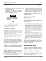
1
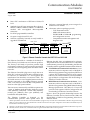
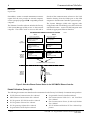
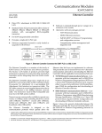
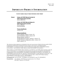
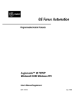
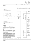
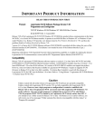
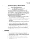
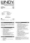
This Datasheet for the
IC697CMM741
Series 90-70 MMS or TCP/IP Ethernet LAN Interface.
http://www.cimtecautomation.com/parts/p-14776-ic697cmm741.aspx
Provides the wiring diagrams and installation guidelines for this GE Series 90-30
module.
For further information, please contact Cimtec Technical Support at
1-866-599-6507
[email protected]
1
Communications Modules
68
IC697CMM741
Ethernet Controller
GFK-0532K
August 1997
Communications Modules
Ethernet Controller (IC697CMM741)
datasheet GFK-0532K
D
Direct PLC attachment to IEEE 802.3 CSMA/CD
LAN
D
Standard 15-pin AUI port connection allows choice of
10Base5, 10Base2, 10BaseT, 10BaseF, or 10Broad36
medium with user-supplied 802.3-compatible
transceiver
D
D
D
D
Software is retained through power outages for a
minimum of six months
D
Alternative software packages provide:
-
For IC697 programmable controllers
Occupies a single slot in PLC rack
-
Software (separately licensed) is easily loaded or
upgraded via RAM load
TCP/IPcommunications
MMS/OSIcommunications
Full MS-DOSr or WIndowsr programming
and configuration services
Comprehensive station management and
diagnostic tools
CABLE PLANT
TRANSCEIVER
a44662
TRANSCEIVER
TRANSCEIVER
TRANSCEIVER
*
MS-DOS
or WINDOWS
PROGRAMMING
SOFTWARE
LOCAL GSM
SYSTEM
MANAGER
ETHERNET
CONTROLLER
ETHERNET
CONTROLLER
NETWORK GSM
IC697
PLC
IC697
PLC
SYSTEM
MANAGER
* TRANSCEIVER CABLE
Figure 1. Ethernet Controller Connects the IC697 PLC to a 802.3 LAN
The Ethernet Controller is a member of the family of
IC651 Factory LAN hardware and software products.
The Factory LAN family of products provides high
performance solutions for interconnecting automation
controllers and for integrating them into multi-vendor
networks.
The Ethernet Controller plugs into a single slot in an
IC697 PLC rack and provides an 802.3-standard 15-pin
D-connector for attachment of a user-supplied AUI
(Attachment Unit Interface) or transceiver cable. The
AUI cable connects to a user-supplied transceiver that is
directly connected to the 10Μbps Ethernet network
cable. The transceiver must be 802.3-compatible and
must have the SQE option enabled.
Transceivers are commercially available to operate on a
variety of 10Μbps media including thickwire coaxial
cable (10Base5), ThinWiret coaxial cable (10Base2),
twisted pair (10BaseT), fiber optic (10BaseF), and
broadband cable (10Broad36).
The Ethernet Controller is designed so the
communications protocols which operate above the
Ethernet data link layer are implemented in software.
This permits the user to choose between two* alternative
communication protocols by downloading the Ethernet
Controller with the applicable Communications Software:
D TCP/IP-Ethernet Communications Software - Communicate with host computers and/or MS-DOS or
WIndows Programmer using proprietary SRTP over
a 4-layer TCP/IP (Internet) protocol stack; requires
either a Local or Network Factory LAN System Manager (GSM) for configuration and downloading of
Ethernet Controller software.
D MMS-Ethernet Communications Software - Communicate with host computers and/or MS-DOS or
Windows Programmer using MMS (Manufacturing
Message Specification - ISO 9506) on a 7-layer OSI
protocol stack; requires GSM for configuration and
downloading of Ethernet Controller software.
Figure 1 shows the general relationship between the
Ethernet Controller, the local and network GSMs, and
the MS-DOS or Windows Programming Software on
Ethernet station.
* A third option, SRTP communications software (IC641SWP711) supports only communications with MS-DOS or WIndows Programmers using
SRTP over a 4-layer OSI protocol stack; this Ethernet Controller software does not require configuration and can be downloaded directly from
the MS-DOS or Windows Programer.
t ThinWire is a trademark of Digital Equipment Corporation; r IBM is a registered trademark of International Business Machines Corporation.
r MS-DOS, Windows, Windows 95 , and Windows NT are registered trademarks of Microsoft Corporation.
t
Series 90 -70 Programmable Controller Data Sheet Manual
GFK-0600F
68-1
Communications Modules
2
GFK-0532K
August 1997
Features of the Ethernet Controller
The Ethernet Controller is a single-slot module that is
inserted directly into the IC697 CPU rack.
Connection to the Ethernet LAN is made via a
transceiver cable to an external transceiver. The
transceiver and cable are provided by the user. The
transceiver is attached directly to the IEEE 802.3
network cable. The Ethernet Interface operates at 10
Mbps on the Ethernet LAN.
The Ethernet Controller uses three LEDs for indicating
the status of the interface. A battery is provided to
maintain the contents of Random Access Memory
(RAM) over power outages.
The Ethernet Controller provides basic functions in
firmware or Read Only Memory (ROM). This firmware
includes self-test diagnostics and special software that
allows you to configure and test your interface in the
PLC and on the Ethernet LAN. It also allows you to load
the communications software into RAM either from the
GSM (serially or over the network), or from an MS-DOS
or Windows OSI-Ethernet Programmer station.
The communications software is stored in RAM so you
can upgrade communications software without replacing
ROM chips. The battery maintains the contents of RAM
over power outages.
“Soft Switches” are used to tailor the Ethernet Controller
to your application. The MS-DOS or Windows
Configuration Software package is used to configure the
Ethernet Controller in the IC697 PLC, and to set the soft
switches for the Ethernet Controller.
More detailed information about the Ethernet
Controller, hardware installation, attachment to the
Ethernet LAN, and Ethernet software follows this
overview. For a complete description, refer to the
User’s Manual that applies to the software you choose
to run on it. These related publications are listed on
page 8.
68-2
Ethernet Controller
IEEE 802.3 Media
The Ethernet Controller can operate on any of the
following media with the appropriate user-supplied
transceiver cable and transceiver. IEEE 802.3 specifies
the definitive requirements of each medium.
10Base5 Coax: 10Base5 uses a 0.4 inch diameter 50-ohm
coaxial cable. The maximum length of a cable segment
(single span of cable) is 500 meters. The distance
between any two stations must be a multiple of 2.5
meters. A maximum of 100 stations is allowed on a
thickwire Ethernet segment.
10Base2 Coax: 10Base2 uses a 0.2 inch diameter 50-ohm
coaxial cable. The maximum length of a thinwire cable
segment is 185 meters. A maximum of 30 stations is
allowed on a thinwire Ethernet segment.
10BaseT: 10BaseT uses a twisted pair cable of up to 100
meters in length between each node and a hub or
repeater. Typical hubs or repeaters support 6 to 12
nodes connected in a star wiring topology.
10BaseF: 10BaseF has two variations that both use the
same type of fiber optic cable: 10BaseFP can support up
to 33 nodes at distances of up to 500 meters from a
passive star; 10BaseFL supports up to 2000 meters
between a node and a repeater (a multi-port repeater
would thus constitute a star). Additionally, 10BaseFB
provides a means of interconnecting (only) repeaters by
up to 2000 meters of (the same) fiber optic cable.
Note
Various Ethernet baseband media can be
interconnected by appropriate repeaters.
Capabilities and limitations are defined in
IEEE 802.3 Chapter 13, “System Considerations for Multi-Segment Networks”.
10Broad36: 10Broad36 uses 75-ohm coaxial cable and
CATV-like media components (taps, amplifiers,
headend translators, etc.) to support hundreds of nodes
at distances of up to 2800 meters. Broadband cannot be
connected to baseband via repeaters. Broadband cable
plant design and installation must be in accordance
with IEEE 802.7 and requires special expertise. GE
Fanuc recommends you contract professional
specialists for these services. Consult your GE Fanuc
sales representative or field service office for help in
identifying local specialists.
t
Series 90 -70 Programmable Controller Data Sheet Manual
GFK-0600F
Communications Modules
3
GFK-0532K
August 1997
Ethernet Controller
Module Physical Description
User Maintenance Items
Figure 2 shows the maintenance controls and indicators
of the Ethernet Controller.
The Ethernet Controller has the following useraccessible elements:
D
Three LEDs: located at the top front of the Ethernet
Controller and are visible through a window in the
front door.
D
Default Station (MAC) Address Label: affixed on
the outside of the plastic housing. This MAC station
address is used for network communications,
unless overridden by the user.
D
Restart Button: located immediately below the
LEDs.
D
Battery and Battery Holder: located to the right of
LEDs (between Restart button and serial port).
D
Local Serial Port: 9-pin female connector for RS-232
Interface.
D
AUI Port: 15-pin female connector with slide-lock
for transceiver cable. Located beneath the local
serial port.
a44719
LEDS
RESTART
PUSHBUTTON
OPEN
REPLACEMENT
BATTERY
CONNECTOR
CURRENTLY
INSTALLED
BATTERY
CONNECTOR
9–PIN
SERIAL
PORT
B
A
T
T
E
R
Y
MODEL 70
CMM 741
MODULE OK
ONLINE
STATUS OK
ON OR BLINK= OK
PUSH TO RESTART
LAN INTERFACE.
PUSH AND HOLD
TO REQUEST
LAN INTERFACE
DOWNLOAD. (INOP
WHEN RUNNING
DIAGNOSTICS)
BATTERY
CONNECTIONS
15–PIN
ETHERNET
CONNECTOR
INSTALL NEW
BATTERY BEFORE
UNPLUGGING OLD
BATTERY. USE
IC697ACC701
SERIAL
PORT
RS–232
DTE
2 TX (OUT)
3 RX (IN)
7 GND
DEFAULT
STATION
ADDRESS
LABEL
PUSH
SLIDE FROM
FRONT TO
LOCK: FROM
BACK TO
RELEASE
TRANSCEIVER
CABLE
MODULE
IC697CCM741
LABEL
44A726758–117R01
TRANSCEIVER
CABLE
The Ethernet Controller board indicators consist of
three Light Emitting Diodes (LEDs):
D
MODULE OK
D
ONLINE
D
STATUS OK
See Figure 2 for LED location, and Table 1 for a
description of these indicators.
WARNING
GROUND
WIRE
Module Indicators
Figure 2. Ethernet Controller Board
t
Series 90 -70 Programmable Controller Data Sheet Manual
GFK-0600F
68-3
Communications Modules
4
GFK-0532K
August 1997
Ethernet Controller
Table 1. Ethernet Controller Indicators
Indicator
MODULE OK
ONLINE
STATUS OK
Status
Description
ON
This LED is ON if the Ethernet Controller has passed diagnostics and its hardware is
operating properly.
OFF
It is OFF if the module fails a diagnostic test or if a fatal failure is detected while the board is
running.
BLINKING
This LED is blinking if the module is running diagnostics or is in Soft Switch entry state.
ON
This LED is ON when the Ethernet Controller is connected to and ready to communicate on the
network.
OFF
This LED is OFF when:
- the station is not communicating in the network due to disconnection or a disruption of
the cable.
- the local station has malfunctioned.
- the Ethernet Controller has been commanded not to enter the network or is in a
state where network operation is inappropriate, such as Soft Switch Entry state or local
loading.
BLINKING
It is BLINKING when the module is transferring data on the network or loading over the
network.
ON
This LED is ON if the module is running without exception conditions.
OFF
This LED is OFF if the module is running and detects an event that calls for supervisory
attention. In this case you should connect the GSM and follow the instructions in Chapter
8 of the User’s Manual to obtain further information.
BLINKING
This LED is BLINKING if the module is loading or looking for a load source for the LAN
Interface software.
Restart Button
The Restart button serves two functions: Restart, and
Restart and Reload. The Restart button is inaccessible
when the door to the Ethernet Controller is closed.
Restart: Pressing the Restart button (for less than 5
seconds) forces a restart of the Ethernet Controller. The
power-up diagnostics run and the software on the
module is restarted.
Restart and Reload: Pressing and holding the Restart
button for 5 seconds or more requests a restart and
reload of the Ethernet Controller. When the Restart
button is pressed, all LEDs go out. After 5 seconds have
elapsed, the STATUS OK LED will come ON to indicate
that the Ethernet Controller will request a reload. Upon
release of the button, the power-up diagnostics run and
the Ethernet Controller requests a reload.
See
“Configuring and Loading the Ethernet Controller” for
more information.
68-4
Note
Any data being transferred by the
Ethernet Controller at the time of the
Restart, or Restart and Reload, will be lost.
The Restart Button is not operable during
the Ethernet Controller diagnostic phase.
The Ethernet Controller is in diagnostic
phase when the BOARD OK LED is
BLINKING and the ONLINE and STATUS
OK LEDs are OFF.
Battery
The battery and battery holder are located to the right
of the LEDs. The battery connectors are located on the
board between the Restart button and the 9-pin serial
port connector.
When connected, the battery preserves the contents of
RAM when there is no power to the board. The battery
will maintain the RAM contents for a minimum of six
months.
t
Series 90 -70 Programmable Controller Data Sheet Manual
GFK-0600F
Communications Modules
5
GFK-0532K
August 1997
Ethernet Controller
Table 3. Transceiver Port Pin Assignment
Local Serial Port
The 9-pin serial port (RS-232 interface) is used to
connect locally to the Factory LAN System Manager
(GSM) terminal. The communication software may be
loaded through this port. The Ethernet Controller
module is a Data Terminal Equipment (DTE) device.
The pinouts of the port are shown in Table 2.
Table 2. RS-232 Port Pin Assignment
Pin
Signal
Description Number
2
TX
Transmit data (out)
3
RX
Receive data (in)
7
GND
Signal Ground
A cable is needed to connect the GSM to the Ethernet
Controller. Figure 3 illustrates one type of GSM cable
connection.
AUI Port
The 15-pin AUI port is located on the front bottom edge
of the Ethernet controller board. This port connects the
transceiver cable to the Ethernet Controller. The
external 802.3 transceiver connects to the Ethernet
network. Connector pinouts are shown in Table 3.
Caution
Pin
Signal
Description
1
GND
Signal Ground
2
CP+
Collision Presence +
3
TX+
Transmit +
4
GND
Signal Ground
5
RX+
Receive +
6
GND
Signal Ground
7
NC
Not Connected
8
GND
Signal Ground
9
CP–
Collision Presence –
10
TX–
Transmit –
11
GND
Signal Ground
12
RX–
Receive –
13
+12
+12 Volts
14
GND
Signal Ground
15
NC
Not Connected
Shell
PG
Protective Ground
Station Address Label
The Default Station (MAC) Address label lists the station
address to be used by this module, unless a locally
assigned address is set by the user via “Soft Switches”.
It is found on the right-hand outside of the plastic
housing.
PLC power must be OFF when
connecting or disconnecting the
transceiver.
Note
Transceiversmust be 802.3-compatible and
must have the SQE option Enabled.
t
Series 90 -70 Programmable Controller Data Sheet Manual
GFK-0600F
68-5
Communications Modules
6
GFK-0532K
August 1997
Ethernet Controller
9-PIN
SERIAL PORT
ON
PERSONAL
COMPUTER
9-PIN
MALE
Î
Î
Î
Î
PIN
RXD
TXD
*2
*3
GND
*5
PIN
RS-232 CABLE
9-PIN
FEMALE
2
TXD
3
RXD
7
GND
9-PIN
MALE
Î
Î
Î
Î
a45182
ETHERNET
INTERFACE
MODULE
SERIAL
PORT
9-PIN
FEMALE
* THE PINS AND CONNECTOR MAY BE DIFFERENT FOR SOME COMPUTERS OR TERMINALS, BUT
THE SIGNAL NAMES WILL BE THE SAME. CONSULT THE MANUAL FOR YOUR COMPUTER OR ASCII
TERMINAL FOR THE CORRECT SIZE AND PIN NUMBERS.
Figure 3. Cable to Connect the GSM to the Ethernet Interface
Installation
Note
This section describes the physical installation of the
Ethernet Controller into the IC697 PLC rack.
The Ethernet Controller will not
operate properly if there are empty
slots to its left.
1. Read and record the 12-digit Default Station Address from the printed label on the Ethernet Controller.
a45349
C E B
P T T
U H M
E
R
N
E
T
P
S
A Station Configuration Data Form is provided in
the User’s Manual, for your convenience in
recording the Station Configuration Information.
2. Be sure the IC697 PLC rack power is OFF.
3. Connect the Ethernet Controller battery:
Hold the module so the front cover is facing you
with the hinge to the right. The tab on the battery
cable should face to the right, away from the board
surface.
Open the front cover of the Ethernet Controller
module. The battery is mounted in the holder, but
is not connected to the board. (See Figure 2.)
Connect the battery to either of the battery
connectors on the card. Press down firmly to lock
the battery connector in place.
GROUND
WIRE
TO
802.3
TRANSCEIVER
Figure 4. IC697 PLC Rack Layout
5. Connect the free end of the ground wire (18 inch
long green wire attached to the Ethernet module) to
the ground lug at the side of the IC697 PLC rack.
(See Figure 4.)
Caution
4. Slide the Ethernet Controller into the slot for which
it was configured in the system - normally the first
available slot to the right of the CPU or Bus Transmitter Module (BTM). (See Figure 4. for the IC697 PLC
rack layout)
The ground wire must be securely
fastened to the chassis of the IC697
PLC rack and the rack must be
properly grounded. Failure to do so
may cause improper operation of the
LAN.
Press firmly to lock the board in place, but do not
force the board.
68-6
TRANSCEIVER
CABLE
t
Series 90 -70 Programmable Controller Data Sheet Manual
GFK-0600F
Communications Modules
7
GFK-0532K
August 1997
Ethernet Controller
6. Connect the transceiver cable to the 15-pin AUI Port
of the Ethernet Controller.
The other end of the transceiver cable should be
connected to an external transceiver which is
attached to the IEEE 802.3 network.
Warning
PLC power must be OFF when
connecting or disconnecting the
transceiver.
Note
Transceivers must be 802.3-compatible and
must have the SQE option Enabled.
7. Set the CPU Run/Stop switch to STOP.
8. Power up the PLC rack.
Correct Results of Installation
During Power-Up: The MODULE OK LED on the front
of the Ethernet Controller will BLINK during power-up
diagnostics, and continue to BLINK while waiting for
configuration data from the CPU.
After Power-Up: Once the Ethernet Controller has
completed power-up diagnostics (about 15 seconds):
The MODULE OK LED will stop blinking, and should
remain ON.
The ONLINE LED may be ON, OFF or BLINKING.
The STATUS OK LED will normally be BLINKING (unless software was previously loaded), indicating that
the Ethernet Interface needs to be loaded.
If you get these indications, physical installation and
power-up are complete. You may continue with
Procedure 3 (or the next appropriate procedure) in
Chapter 2 of the appropriate controller User’s Manual.
Corrective Actions
MODULE OK OFF indicates a hardware fault, either in
the Ethernet Controller or in the PLC, that prevents the
Ethernet Controller from operating.
D
Cycle power on the PLC to determine whether the
fault is intermittent or a “hard” failure.
t
Series 90 -70 Programmable Controller Data Sheet Manual
GFK-0600F
D
If MODULE OK remains OFF, examine the PLC
Fault Table for diagnostic information and take
appropriate action. See the IC697 Programmable
Controller Installation and Operation Manual for
information on the PLC Fault Table.
For detailed troubleshooting information, refer to the
applicable User’s Manual.
Configuring and Loading the
Ethernet Controller
As described earlier, the Ethernet Controller can be
loaded with one of the alternative communications protocols. See Figure 5.
1. TCP/IP-Ethernet Communication Software. If the
Ethernet Controller must support TCP/IP communications to MS-DOS or WindowsTCP/IP-Ethernet
Programming software to other IC69* PLCs, CIMPLICITY products, or Host Communications Drivers applications, you must create a configuration file
on the Factory LAN System Manager (GSM) and
download that file together with the TCP/IP communications software. The GSM software runs on a
separate computer .
2. MMS-Ethernet Communications Software. If the
Ethernet Controller must support MMS communications, you must create a configuration file on the
Factory LAN System Manager (GSM) and download
it together with the MMS communications software.
The GSM is a separate computer running GSM software.
See the applicable user’s manual for instructions on
configuring and loading the Ethernet Controller. These
operations are necessary before the LAN Interface can
be used by your application.
Station Management Software
Operating a local area network entails certain LAN
management activities. For the Factory LAN, this
includes network performance measurement, fault
diagnosis,
configuration
management,
and
downloading the appropriate configuration file and
communication software to network nodes.
Many features to support these activities are built
directly into the Ethernet Controller.
68-7
Communications Modules
8
GFK-0532K
August 1997
Ethernet Controller
Nonetheless, certain occasional maintenance activities
require that the user provide an external computer,
such as a properly equipped IBMr-compatible personal
computer.
The Ethernet Controller software includes the Factory
LAN System Manager (GSM) to run on this external
computer. The GSM is used to store on disk and to
download the communications software to the LAN
Interface directly from the COM1 port on the GSM
computer to the Ethernet Controller 9-pin serial port.
The System Manager (GSM) also supports node
configuration and downloading across the LAN from a
centralized location. A network GSM computer must
include an appropriate Ethernet Interface.
ALTERNATIVE ETHERNET PROTOCOL STACKS
TCP/IP
Host Computer Software
Host Communications Drivers
Applications (may require
3rd–party software)
Host
Applications
ÎÎÎÎÎÎÎÎ
ÎÎÎÎÎÎÎÎ
ÎÎÎÎÎÎÎÎ
ÎÎÎÎÎÎÎÎ
ÎÎÎÎÎÎÎÎ
ÎÎÎÎÎÎÎÎ
IC641 Programming Software
IC641 TCP/IP–Ethernet Prog. Software
IC641SWP713 (Includes
IC651ENS042 software below)
GFK–1029
IC697 PLC
Ethernet
Controller
Software
a45381c
MMS/OSI
TCP/IP–Ethernet
IC651ENS042
GFK–1004
(Loaded from the GSM)
Host Computer Software
– CIMPLICITY MMS
– 3rd–party MMS
IC641 Programming Software
IC641 OSI–Ethernet Prog. Software
IC641SWP711
GFK–0780
MMS–Ethernet
IC651ENS040
GFK–0868
(Loaded from the GSM)
Load ONLY ONE Ethernet Controller Software
IC697 PLC
Ethernet
Controller
Hardware
Ethernet
Controller
IC697CMM741
Figure 5. Alternative Ethernet Protocol Stacks for the IC697CMM741 Ethernet Controller
Related Publications (Factory LAN)
The following documents are related user documentation for the Factory LAN family of communication products.
D
D
D
D
D
D
TCP/IP-Ethernet Communications User’s Manual
MMS-Ethernet Communications User’s Manual
PLC Programmer TCP/IP-Ethernet User’s Manual
PLC Programmer-Ethernet User’s Manual
PLC Programming Software User’s Manual
Programmable Controller Reference Manual
68-8
D Programmable Controller Installation Manual
D Host Communications Toolkit C/C++ and Visual Basic
User’s Manual
D Host Communications Drivers for Microsoft Windows
User’s Manual
D TCP/IP Windows 95/Windows NT User’s Manual Supplement
t
Series 90 -70 Programmable Controller Data Sheet Manual
GFK-0600F
Communications Modules
9
GFK-0532K
August 1997
Ethernet Controller
Table 4. Module Specifications [
Power Consumption
(Typical):
Power consumption for the Ethernet Controller includes external RS-232 loads and the external
transceiver. The module is powered by the rack. The power supply must provide +12 Vdc.
+5 Vdc
+12 Vdc
1.00 A
0.5 A
Memory Retention:
An on-board battery provides backup power (at least 6 months) when power is removed from the CPU
rack containing the Ethernet Controller.
Physical Dimensions:
Circuit Board:
Mounting:
Connectors:
InterfaceSpecifications:
6.3 x 9.19 inches (160 x 233 mm). Occupies a single slot in an IC697 PLC rack.
The module plugs into the IC697 CPU rack in the first available slot to the right of the CPU or BTM.
(Bus Receiver Module if remote rack)
- LED Indicators: MODULE OK, ONLINE, STATUS OK
- Restart pushbutton and Battery connectors - front edge of board behind the hinged door
Serial and Transceiver Ports
- Serial Port: 9-pin female, D-connector (to Local GSM)
- Transceiver Port: 15-pin female, D-connector (to Ethernet transceiver cable and network)
LAN (to Network GSM and/or IC641-Ethernet Programmer)
IEEE 802.2 Logical Link Control Class I
IEEE 802.3 CSMA/CD Medium Access Control 10Mbps
Serial Port: RS-232 DTE, 9600 bps
Transceiver Port: Ethernet, IEEE 802.3 CSMA/CD, Transceiver SQE must be Enabled.
[ Refer to GFK-0867B, or later for product standards and general specifications. For installations requiring compliance to more
stringent requirements (for example, FCC or European Union Directives), refer to Installation Requirements for Conformance to
Standards.
Table 5. Ordering Instructions
Ethernet Controller
Ethernet Controller Module
TCP/IP
Ethernet Controller Software
TCP/IP
-Ethernet Programming
Software and LAN Interface
Software (MS-DOS version)
(Windowsversion)
MMS/OSI
Ethernet Controller Software
OSI-Ethernet Programming
Software
IC697CMM741
TCP/IP Software and Documentation for the PLC Ethernet
Controller (Includes GSM).
IC651ENS042
Software and Documentation for the IC641-TCP/IP
-Ethernet
Programmer and Software and Documentation for the IC697 PLC
(IncludesIC651ENS042).
IC641SWP713
TCP/IPWindowsr95/Windows NTr MS-DOSr Box version of above.
IC641SWC716
MMS Software and Documentation for the PLC Ethernet
Controller (Includes GSM).
IC651ENS040
Software and Documentation for the IC641 OSI-Ethernet Programmer which includes SRTP-Ethernet software and documentation.
IC641SWP711
Note: For Conformal Coat option, or Low Temperature Testing option please consult the factory for price and availability.
Replacement Parts
PLC Power Supply
120/240 VAC or 125 VDC Input, 100 watt Power Supply
24 VDC Input, 90 watt Power Supply
48 VDC Input, 90 watt Power Supply
(One of these Power Supplies is a prerequisite, since +5 Vdc and +12 Vdc are
required by the Ethernet Controller Module)
IC697PWR711
IC697PWR724
IC697PWR748
Battery
Lithium Battery, 3V, to protect LAN Controller memory from power loss
IC697ACC701
t
Series 90 -70 Programmable Controller Data Sheet Manual
GFK-0600F
68-9