1
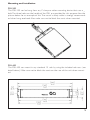
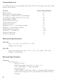
Introduction . . . . . . . . . . . . . . . . . . . . . . 2
Using the PSU . . . . . . . . . . . . . . . . . . . . 2
Mounting and Installation. . . . . . . . . . . . 5
Mechanical Specifications . . . . . . . . . . . . 6
Electrical Specifications . . . . . . . . . . . . . 6
Warranty . . . . . . . . . . . . . . . . . . . . . . . . 7
MANUAL
Compatibility List . . . . . . . . . . . . . . . . . . 6
Introduction
Congratulations on your purchase of the Rosco Laboratories PSU-200 or PSU-400.
These power supplies are intended to provide power and data to the majority of
lighting accessories available on the market today.This includes, but is not limited too,
color scrollers, gobo rotators, and I-Cue units. If you are unsure whether your particular accessories are compatible, please check the compatibility listing later in this manual or the updated list online at www.rosco.com . Once RDM becomes a standard and
RDM accessories become available, an upgrade will be available for both the PSU-200
and PSU-400 to support this as well.
Both the PSU-200 and PSU-400 units provide similar functionality in different packages and power capabilities.The PSU-200 is a 200W power supply that can be hung
on a baton or set on a flat surface.The PSU-400 has two (2) 200W supplies, for a
total of 400W, and is in a standard 19 rack-mount frame (2U height, 13 depth).
Using the PSU
Power Connection
The power to the PSU is connected to a fused male IEC receptacle mounted on the
PSU. Input power can be 85-264VAC 47-63Hz or 120-370VDC.The standard fuse is
a 5x20mm 6.3A / 250V Slo-Blo.
Data and Accessory Connections
The common data input is standard DMX-512 through a male 5-pin XLR. A passthrough connection (all pins) is available on the female 5-pin XLR.The accessory connections are female 4-pin XLRs wired as: Pin 1 = Ground, Pin 2 = Data-, Pin 3 =
Data+, Pin 4 = 24VDC.There are also accessory return connections, male 4-pin XLRs
wired as: Pin 1 = Ground, Pins 2 & 3 = 120_ termination, Pin 4 = 24VDC.
Indicators & Controls
The front panel is identical on both the PSU-200 and PSU-400.The button controls
termination of the incoming DMX signal.Termination is deactivated by pushing the
button in, most easily done with a pen (it will be behind the panel when pushed in).
The yellow LED next to the button indicates that termination is on.The blue LED
indicates the presence of an RDM signal (when upgrade is installed).The green LED
indicates the presence of an incoming DMX signal.The red LED indicates that power
is on.
2
System Layout
A typical system layout is shown below.
Note that both accessory chains are terminated.The top row of accessories is using
the channel return (see below), which terminates the chain.The bottom row of accessories is using a separate terminator (made with a 4-pin XLR and 120_ resistor).This
is recommended to maintain the integrity of the data in the chain.
The channel returns are provided for two reasons. First of all, they provide an easy
way to terminate the accessory chain. Secondly, they will reduce voltage drops on
long chains of accessories by providing a supply at both ends of the chain. Generally
the voltage drop is cut roughly in half by using a channel return.This can nearly double
your maximum cable run.
Load Considerations
The load that the PSU can deliver to the accessories is limited and must be taken into
account when setting up the system.To begin with, each accessory has a constant
power consumption and a peak power consumption.The constant power consumption is generally when the accessory is plugged in, but not operating.The peak power
consumption generally occurs when motors start or change directions. We advise
using the peak power consumption when calculating the channel load on the power
supply (this is the number given in the compatibility list).This should give a comfortable margin of safety regardless of the nature of the show.
On both PSUs, there are 4 channels (consisting of the marked channel and the corresponding return). Basically, the channel load is calculated by adding the power consumption of every accessory on the channel.
3
On the PSU-200, the sum of all four (4) channel loads should not exceed 200W.
On the PSU-400, the sum of channel loads from channels 1 & 2 should not exceed
200W.The sum of channel loads from channels 3 & 4 should not exceed 200W.
In either case, an even distribution of the load over all channels is recommended as it
will minimize problems caused by voltage drops and long cable runs. Using cable with
heavy-gauge power wires can also reduce problems.
If erratic behavior is noticed on a channel, try reducing the load on that channel and
make sure that it is properly terminated.
An example system using the PSU-200:
The design calls for 20 Wybron Forerunners (10W each). Since this is a maximum
load of 200W, it is compatible with the PSU-200. Ideally, there would be 5 on each
channel (an even distribution of 40W per channel), but 10 on a channel, or even 20
on one channel would be acceptable as long as the cable run is relatively short.
An example system using the PSU-400:
The design calls for 16 Rosco I-Cues (17W each) and 16 DHA Double Indexing
Rotators (6W each).This is a total load of 368W, which is compatible with the PSU400. However, this exceeds the 200W limit on channels 1 & 2 (or 3 & 4), so the load
must be split between at least two channels.The ideal would be 4 of each accessory
on each channel, which is 92W per channel and 184W per channel pair (under the
200W limit). Alternatively, there could be 8 of each accessory on channels 1 and 3,
keeping the 184W per channel pair. Again, this is not recommended for long cable
runs.
4
Mounting and Installation
PSU-200
The PSU-200 can be hung from any C-clamp or other mounting device that uses a _
bolt.The three holes on the handle of the PSU are provided for this purpose. See the
picture below for an example of this.The use of a safety cable is strongly recommended when hung overhead. Also make sure not to block the vents when mounted
PSU-400
The PSU-400 can mount in any standard 19 rack by using the included rack ears (see
detail below). Make sure not to block the vents on the rear of the unit when mounted.
5
Compatibility List
The following units are compatible with either PSU and are given with their rated
power consumption.
Product
Rosco I-Cue
Rosco DMX Indexing Rotator
AC Lighting / Apollo Chroma Q Broadway
AC Lighting / Apollo Chroma Q M1,2,5,8
Apollo Roto-Q DMX
City Theatrical DMX Iris
DHA Gobo Carousel
DHA Twin DMX
Rainbow 6 , 8 , 12 Pro Colour Scroller
Rainbow 15 Pro Colour Scroller
GAM Indexable Twin Spin
GAM SX4 — 6 Gobo Tray
Wybron Forerunner
Wybron Lightwand
Power Rating (Watts)
17
6
22
36
12
8.5
18
12
14
29
14.4
10.8
14
10
Mechanical Specifications
PSU-200
Size: 11.7 x 8.3 x 3.6 [297 x 211 x 92]
Weight: 5 lbs [2.3 kg]
PSU-400
Size: (not including rack ears) 17.0 x 13.0 x 3.5 [433 x 329 x 89]
Weight: 15 lbs [6.8 kg]
Electrical Specifications
Common
Data Input (1x)
Male 5-Pin XLR
DMX Compatible Data (Pin 2 is -, Pin 3 is +)
120‰ Termination — Switch Selectable
Isolated Receiver
–15KV (HBM) / –8KV (IEC-1000-4-2 Contact) ESD Protected
Direct Pass-Through (All Pins) to Female 5-Pin XLR for Daisy
Chaining
6
Data/Power Output (4x)
Female 4-Pin XLR
DMX Compatible Data (Pin 2 is -, Pin 3 is +)
120‰ Termination, Line Biased to Mark State
Earth Ground Referenced Transmitters
–15KV (HBM) / –8KV (IEC-1000-4-2 Contact) ESD Protected
24VDC Power (Pin 1 is Ground, Pin 4 is +)
Data/Power Return (4x)
Male 4-Pin XLR
120‰ Termination (Pins 2 and 3)
24VDC Power (Pin 1 is Ground, Pin 4 is +)
Line Connection
IEC 320 Grounded Inlet w/ Fuse (5x20mm, 6.3A / 250V SloBlo)
85-264VAC 47-63Hz / 120-370VDC
EMI Filter
Power Factor Correction
Internal Protection
Fan on Power Supply
Overtemp Protection on Power Supply (Auto Recovery)
Overload Protection on Power Supply (Auto Recovery)
Environmental
50C Maximum Ambient (Estimated Based on Component
Limits)
PSU-200
Line Connection
2.8A @ 115V, 1.4A @ 230V
Load Capabilities
200W (8.4A @ 24VDC) Combined on All Channels
PSU-400
Line Connection
5.6A @ 115V, 2.8A @ 230V
Internal Protection
8CFM Fan (Vents on Rear)
Load Capabilities
200W (8.4A @ 24VDC) Combined on Channels 1&2
200W (8.4A @ 24VDC) Combined on Channels 3&4
Warranty
Rosco Laboratories will provide a limited 1-yr warranty on parts and labor for
the PSU-200 and PSU-400 units, but not for the lamp.
7
www.rosco.com
52 Harbor View Avenue, Stamford, CT 06902
(203)708-8900 • 1(800)ROSCO NY • Fax: (203)708-8919
1120 N. Citrus Avenue, Hollywood, CA 90038
(323)462-2233 • 1(800)ROSCO LA • Fax: (323)462-3338
Also in:Toronto, London, Madrid, São Paulo and Sydney