1
w w w . k e i th l e y. c o m
Model 2701 Ethernet-Based
DMM / Data Acquisition System
User’s Manual
2701-900-01 Rev. F / August 2011
A
G R
E A T E R
M E A S U R
E
O F
C O N F I D E N C E
2701-900-01.book Page 1 Wednesday, August 3, 2011 9:43 AM
Model 2701 Ethernet-Based DMM / Data Acquisition System
User’s Manual
©2002-2011, Keithley Instruments, Inc.
All rights reserved.
Cleveland, Ohio, U.S.A.
Document Number: 2701-900-01 Rev. F / August 2011
2701-900-01.book Page 2 Wednesday, August 3, 2011 9:43 AM
2701-900-01.book Page 1 Wednesday, August 3, 2011 9:43 AM
Safety Precautions
04/09
The following safety precautions should be observed before using this product and any associated instrumentation.
Although some instruments and accessories would normally be used with non-hazardous voltages, there are
situations where hazardous conditions may be present.
This product is intended for use by qualified personnel who recognize shock hazards and are familiar with the safety
precautions required to avoid possible injury. Read and follow all installation, operation, and maintenance
information carefully before using the product. Refer to the user documentation for complete product specifications.
If the product is used in a manner not specified, the protection provided by the product warranty may be impaired.
The types of product users are:
Responsible body is the individual or group responsible for the use and maintenance of equipment, for ensuring
that the equipment is operated within its specifications and operating limits, and for ensuring that operators are
adequately trained.
Operators use the product for its intended function. They must be trained in electrical safety procedures and proper
use of the instrument. They must be protected from electric shock and contact with hazardous live circuits.
Maintenance personnel perform routine procedures on the product to keep it operating properly, for example,
setting the line voltage or replacing consumable materials. Maintenance procedures are described in the user
documentation. The procedures explicitly state if the operator may perform them. Otherwise, they should be
performed only by service personnel.
Service personnel are trained to work on live circuits, perform safe installations, and repair products. Only properly
trained service personnel may perform installation and service procedures.
Keithley Instruments products are designed for use with electrical signals that are rated Measurement Category I
and Measurement Category II, as described in the International Electrotechnical Commission (IEC) Standard IEC
60664. Most measurement, control, and data I/O signals are Measurement Category I and must not be directly
connected to mains voltage or to voltage sources with high transient over-voltages. Measurement Category II
connections require protection for high transient over-voltages often associated with local AC mains connections.
Assume all measurement, control, and data I/O connections are for connection to Category I sources unless
otherwise marked or described in the user documentation.
Exercise extreme caution when a shock hazard is present. Lethal voltage may be present on cable connector jacks
or test fixtures. The American National Standards Institute (ANSI) states that a shock hazard exists when voltage
levels greater than 30V RMS, 42.4V peak, or 60VDC are present. A good safety practice is to expect that hazardous
voltage is present in any unknown circuit before measuring.
Operators of this product must be protected from electric shock at all times. The responsible body must ensure that
operators are prevented access and/or insulated from every connection point. In some cases, connections must be
exposed to potential human contact. Product operators in these circumstances must be trained to protect
2701-900-01.book Page 2 Wednesday, August 3, 2011 9:43 AM
themselves from the risk of electric shock. If the circuit is capable of operating at or above 1000V, no conductive part
of the circuit may be exposed.
Do not connect switching cards directly to unlimited power circuits. They are intended to be used with impedancelimited sources. NEVER connect switching cards directly to AC mains. When connecting sources to switching cards,
install protective devices to limit fault current and voltage to the card.
Before operating an instrument, ensure that the line cord is connected to a properly-grounded power receptacle.
Inspect the connecting cables, test leads, and jumpers for possible wear, cracks, or breaks before each use.
When installing equipment where access to the main power cord is restricted, such as rack mounting, a separate
main input power disconnect device must be provided in close proximity to the equipment and within easy reach of
the operator.
For maximum safety, do not touch the product, test cables, or any other instruments while power is applied to the
circuit under test. ALWAYS remove power from the entire test system and discharge any capacitors before:
connecting or disconnecting cables or jumpers, installing or removing switching cards, or making internal changes,
such as installing or removing jumpers.
Do not touch any object that could provide a current path to the common side of the circuit under test or power line
(earth) ground. Always make measurements with dry hands while standing on a dry, insulated surface capable of
withstanding the voltage being measured.
The instrument and accessories must be used in accordance with its specifications and operating instructions, or
the safety of the equipment may be impaired.
Do not exceed the maximum signal levels of the instruments and accessories, as defined in the specifications and
operating information, and as shown on the instrument or test fixture panels, or switching card.
When fuses are used in a product, replace with the same type and rating for continued protection against fire hazard.
Chassis connections must only be used as shield connections for measuring circuits, NOT as safety earth ground
connections.
If you are using a test fixture, keep the lid closed while power is applied to the device under test. Safe operation
requires the use of a lid interlock.
If a
screw is present, connect it to safety earth ground using the wire recommended in the user documentation.
The ! symbol on an instrument means caution, risk of danger. The user should refer to the operating instructions
located in the user documentation in all cases where the symbol is marked on the instrument.
The
symbol on an instrument means caution, risk of danger. Use standard safety precautions to avoid personal
contact with these voltages.
The
The
symbol on an instrument shows that the surface may be hot. Avoid personal contact to prevent burns.
symbol indicates a connection terminal to the equipment frame.
If this
symbol is on a product, it indicates that mercury is present in the display lamp. Please note that the lamp
must be properly disposed of according to federal, state, and local laws.
2701-900-01.book Page 3 Wednesday, August 3, 2011 9:43 AM
The WARNING heading in the user documentation explains dangers that might result in personal injury or death.
Always read the associated information very carefully before performing the indicated procedure.
The CAUTION heading in the user documentation explains hazards that could damage the instrument. Such
damage may invalidate the warranty.
Instrumentation and accessories shall not be connected to humans.
Before performing any maintenance, disconnect the line cord and all test cables.
To maintain protection from electric shock and fire, replacement components in mains circuits - including the power
transformer, test leads, and input jacks - must be purchased from Keithley Instruments. Standard fuses with
applicable national safety approvals may be used if the rating and type are the same. Other components that are
not safety-related may be purchased from other suppliers as long as they are equivalent to the original component
(note that selected parts should be purchased only through Keithley Instruments to maintain accuracy and
functionality of the product). If you are unsure about the applicability of a replacement component, call a Keithley
Instruments office for information.
To clean an instrument, use a damp cloth or mild, water-based cleaner. Clean the exterior of the instrument only. Do
not apply cleaner directly to the instrument or allow liquids to enter or spill on the instrument. Products that consist
of a circuit board with no case or chassis (e.g., a data acquisition board for installation into a computer) should never
require cleaning if handled according to instructions. If the board becomes contaminated and operation is affected,
the board should be returned to the factory for proper cleaning/servicing.
2701-900-01.book Page 4 Wednesday, August 3, 2011 9:43 AM
2701-900-01.book Page i Wednesday, August 3, 2011 9:43 AM
Table of Contents
Section
1
Topic
Page
Getting Started ....................................................................................... 1-1
General information .................................................................................... 1-2
Contact information .............................................................................. 1-2
Safety symbols and terms .................................................................... 1-2
Inspection ............................................................................................. 1-2
Battery .................................................................................................. 1-3
Options and accessories ...................................................................... 1-3
Model 2701 features ................................................................................... 1-6
Plug-in switching modules .......................................................................... 1-7
Pseudocards ........................................................................................ 1-7
Identifying installed switching modules ................................................ 1-7
Front and rear panel familiarization .................................................(QS1) 1-10
Front panel summary ......................................................................... 1-10
Rear panel summary .......................................................................... 1-13
Power-up .........................................................................................(QS2) 1-15
Line power connection ....................................................................... 1-15
Line frequency.................................................................................... 1-16
Setting line voltage and replacing fuse............................................... 1-16
Power-up sequence ........................................................................... 1-17
Keyclick .............................................................................................. 1-19
Display ...................................................................................................... 1-19
Status and error messages ................................................................ 1-19
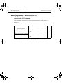
Remote programming — display........................................................ 1-19
Defaults and user setups .......................................................................... 1-21
Saving and restoring setups............................................................... 1-21
Remote programming — default and user setups.............................. 1-26
Remote programming information ............................................................ 1-27
Quick start exercises ......................................................................(QS3) 1-28
Basic DMM measurements — front panel inputs ............................... 1-29
Closing and opening channels — system channel operation ............ 1-31
Simple scanning ................................................................................. 1-35
Trigger and return readings — remote programming......................... 1-38
2
Closing and Opening Switching Module Channels ...................... 2-1
Close/open overview .................................................................................. 2-2
Switching module installation and connections .......................................... 2-4
Module installation................................................................................ 2-4
2701-900-01.book Page ii Wednesday, August 3, 2011 9:43 AM
Table of Contents
Model 2701 Ethernet-Based DMM / Data Acquisition System
Connections.......................................................................................... 2-5
Pseudocards......................................................................................... 2-6
Channel assignments.................................................................................. 2-6
System channel operation........................................................................... 2-7
2-wire functions..................................................................................... 2-8
4-wire functions (paired channels) ........................................................ 2-9
Controlling the system channel........................................................... 2-10
Non-amp and non-measure switching modules ................................. 2-14
Multiple channel operation ........................................................................ 2-16
Controlling multiple channels.............................................................. 2-17
Multiple channel operation anomalies ................................................ 2-22
Dual independent multiplexers ........................................................... 2-24
Identifying installed modules and viewing closed
channels .................................................................................................... 2-30
CARD menu........................................................................................ 2-30
Switching module queries (remote operation) .................................... 2-32
Relay closure count................................................................................... 2-34
Reading relay closure count ............................................................... 2-35
Setting count update interval .............................................................. 2-35
Model 7700 switching module ................................................................... 2-36
Switching module capabilities ............................................................. 2-36
Schematic diagram ............................................................................. 2-37
3
Basic DMM Operation ........................................................................... 3-1
DMM measurement capabilities .................................................................. 3-2
High energy circuit safety precautions ........................................................ 3-3
Performance considerations........................................................................ 3-4
Warm-up ............................................................................................... 3-4
Autozero ............................................................................................... 3-4
LSYNC (line cycle synchronization)...................................................... 3-5
Remote programming — autozero and LSYNC ................................... 3-6
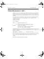
Channel list parameter (<clist>) .................................................................. 3-7
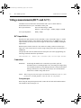
Voltage measurements (DCV and ACV) ..................................................... 3-8
DCV input divider.................................................................................. 3-8
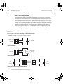
Connections.......................................................................................... 3-8
Volts measurement procedure ............................................................ 3-11
AC voltage measurements and crest factor........................................ 3-12
Low level considerations..................................................................... 3-15
Current measurements (DCI and ACI) ...................................................... 3-17
Connections........................................................................................ 3-17
Amps measurement procedure .......................................................... 3-18
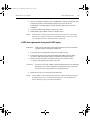
AMPS fuse replacement (front panel AMPS input)............................. 3-19
Resistance measurements (Ω2 and Ω4).................................................... 3-20
Connections........................................................................................ 3-20
Standard resistance measurements ................................................... 3-23
Offset-compensated ohms.................................................................. 3-24
Measurement methods ....................................................................... 3-25
ii
Document Number: 2701-900-01 Rev. F / August 2011
2701-900-01.book Page iii Wednesday, August 3, 2011 9:43 AM
Model 2701 Ethernet-Based DMM / Data Acquisition System
Table of Contents
4-wire common-side (CSID) ohms measurements (7701 module) ....
Temperature measurements .....................................................................
Thermocouples...................................................................................
Thermistors ........................................................................................
4-wire RTDs........................................................................................
Connections .......................................................................................
Temperature measurement configuration...........................................
Temperature measurement procedure ...............................................
Frequency and period measurements ......................................................
Trigger level........................................................................................
Gate time ............................................................................................
Connections .......................................................................................
Frequency and period measurement procedure ................................
Continuity testing ......................................................................................
Connections .......................................................................................
Continuity testing procedure...............................................................
Remote programming for basic measurements........................................
Basic measurement commands .........................................................
Basic measurement programming examples .....................................
Measurement queries ...............................................................................
:FETCh? .............................................................................................
:READ? ..............................................................................................
:MEASure[:<function>]? .....................................................................
[:SENSe[1]]:DATA:FRESh? ................................................................
[:SENSe[1]]:DATA[:LATest]? ...............................................................
Examples............................................................................................
4
3-32
3-33
3-33
3-36
3-37
3-38
3-42
3-45
3-46
3-46
3-46
3-47
3-48
3-48
3-49
3-50
3-51
3-51
3-57
3-58
3-58
3-59
3-60
3-60
3-61
3-61
Range, Digits, Rate, Bandwidth, and Filter ...................................... 4-1
Range ......................................................................................................... 4-2
Measurement ranges and maximum readings ..................................... 4-2
Manual ranging..................................................................................... 4-3
Auto ranging ......................................................................................... 4-3
Scanning .............................................................................................. 4-3
Remote programming — range ............................................................ 4-4
Digits ........................................................................................................... 4-6
Scanning .............................................................................................. 4-6
Remote programming — digits............................................................. 4-6
Rate and bandwidth .................................................................................... 4-8
Rate...................................................................................................... 4-8
Bandwidth........................................................................................... 4-10
Scanning ............................................................................................ 4-10
Remote programming — rate and bandwidth..................................... 4-11
Filter .......................................................................................................... 4-14
Filter characteristics .......................................................................... 4-14
Remote programming — filter ............................................................ 4-20
5
Relative, Math, Ratio, Channel Average, and dB ........................... 5-1
Relative ....................................................................................................... 5-2
Document Number: 2701-900-01 Rev. F / August 2011
iii
2701-900-01.book Page iv Wednesday, August 3, 2011 9:43 AM
Table of Contents
Model 2701 Ethernet-Based DMM / Data Acquisition System
Basic operation ..................................................................................... 5-2
Remote programming — rel ................................................................. 5-4
Math ............................................................................................................ 5-7
mX+b .................................................................................................... 5-8
Percent ................................................................................................. 5-9
Reciprocal (1/X) .................................................................................. 5-10
Basic operation ................................................................................... 5-11
Remote programming — math ........................................................... 5-12
Ratio and channel average ....................................................................... 5-15
Basic operation ................................................................................... 5-16
Remote programming — ratio and channel average .......................... 5-18
dB .............................................................................................................. 5-20
Remote programming — dB ............................................................... 5-20
6
Buffer ......................................................................................................... 6-1
Buffer overview............................................................................................ 6-2
Front panel buffer ........................................................................................ 6-2
Auto clear.............................................................................................. 6-2
Timestamps .......................................................................................... 6-4
Storing readings.................................................................................... 6-5
Recalling readings ................................................................................ 6-6
Buffer statistics...................................................................................... 6-7
Remote programming — buffer................................................................... 6-8
Buffer commands.................................................................................. 6-8
Programming example........................................................................ 6-15
7
Scanning................................................................................................... 7-1
Scanning fundamentals............................................................................... 7-2
Channel assignments ........................................................................... 7-3
Sequential and non-sequential scans................................................... 7-3
Scan process ........................................................................................ 7-4
Trigger models ...................................................................................... 7-4
Scan configuration..................................................................................... 7-11
Scan reset........................................................................................... 7-13
Simple scan ........................................................................................ 7-13
Advanced scan ................................................................................... 7-14
Setting delay ....................................................................................... 7-18
Monitor channel .................................................................................. 7-18
Auto channel configuration ................................................................. 7-20
Saving setup ....................................................................................... 7-21
Auto scan............................................................................................ 7-21
Scan operation .......................................................................................... 7-21
Basic scan .......................................................................................... 7-22
Manual/external trigger scan .............................................................. 7-23
Monitor scan (analog trigger).............................................................. 7-24
Remote programming — scanning............................................................ 7-26
Trigger model...................................................................................... 7-26
Channel setup..................................................................................... 7-27
iv
Document Number: 2701-900-01 Rev. F / August 2011
2701-900-01.book Page v Wednesday, August 3, 2011 9:43 AM
Model 2701 Ethernet-Based DMM / Data Acquisition System
Table of Contents
Buffer ..................................................................................................
Scanning commands..........................................................................
Scanning programming example........................................................
Scanning examples...................................................................................
External trigger scan ..........................................................................
Monitor scan.......................................................................................
8
7-27
7-27
7-32
7-32
7-32
7-35
Triggering................................................................................................. 8-1
Trigger model .............................................................................................. 8-2
Idle........................................................................................................ 8-2
Control source and event detection...................................................... 8-3
Delay (auto or manual)......................................................................... 8-3
Device action ........................................................................................ 8-5
Output trigger ....................................................................................... 8-5
Reading hold (autosettle)............................................................................ 8-6
Hold example ....................................................................................... 8-6
External triggering....................................................................................... 8-7
Digital I/O.............................................................................................. 8-8
External trigger ..................................................................................... 8-8
Voltmeter complete............................................................................. 8-10
External triggering example................................................................ 8-11
External triggering with BNC connections .......................................... 8-14
Remote programming – triggering ............................................................ 8-16
Trigger model (remote operation)....................................................... 8-16
Trigger model operation ..................................................................... 8-18
Triggering commands......................................................................... 8-19
Programming example ....................................................................... 8-20
9
Limits and Digital I/O ............................................................................. 9-1
Limits........................................................................................................... 9-2
Scanning .............................................................................................. 9-4
Basic limits operation............................................................................ 9-4
Digital I/O .................................................................................................... 9-5
Digital input (trigger link input) .............................................................. 9-5
Digital outputs....................................................................................... 9-6
Setting digital output ........................................................................... 9-10
Scanning ............................................................................................ 9-11
Remote programing — limits and digital output ........................................ 9-12
Limits and digital output commands ................................................... 9-12
Limits and digital outputs programming example ............................... 9-14
Application — sorting resistors ................................................................. 9-14
Limits .................................................................................................. 9-14
Digital outputs..................................................................................... 9-17
10
Remote Operations ............................................................................. 10-1
Operation enhancements..........................................................................
Pseudocards ......................................................................................
Autozero .............................................................................................
dB calculation .....................................................................................
Document Number: 2701-900-01 Rev. F / August 2011
10-2
10-2
10-2
10-2
v
2701-900-01.book Page vi Wednesday, August 3, 2011 9:43 AM
Table of Contents
Model 2701 Ethernet-Based DMM / Data Acquisition System
Separate function setups .................................................................... 10-3
DCV input divider................................................................................ 10-3
Multiple channel operation.................................................................. 10-3
System commands.................................................................................... 10-3
Interface.............................................................................................. 10-3
Password ............................................................................................ 10-4
Battery ................................................................................................ 10-5
Miscellaneous system commands ...................................................... 10-6
Ethernet setup ........................................................................................... 10-7
Ethernet standards ............................................................................. 10-7
Typical Ethernet systems.................................................................... 10-7
Ethernet connections ........................................................................ 10-10
Ethernet settings............................................................................... 10-12
Internal web page.................................................................................... 10-16
Opening the web page...................................................................... 10-16
Front panel aspects of Ethernet operation .............................................. 10-20
Error and status messages ............................................................... 10-20
Status indicators ............................................................................... 10-20
LOCAL key ....................................................................................... 10-20
Programming syntax ............................................................................... 10-21
Command words............................................................................... 10-21
Query commands ............................................................................. 10-23
Case sensitivity................................................................................. 10-23
Long-form and short-form versions................................................... 10-23
Short-form rules ................................................................................ 10-24
Program messages........................................................................... 10-24
Response messages ........................................................................ 10-27
Message exchange protocol............................................................. 10-27
RS-232 interface operation ..................................................................... 10-28
Sending and receiving data .............................................................. 10-28
Baud rate .......................................................................................... 10-28
Signal handshaking (flow control)..................................................... 10-29
Terminator......................................................................................... 10-30
Selecting and configuring RS-232 interface ..................................... 10-30
RS-232 connections ......................................................................... 10-32
Error messages ................................................................................ 10-33
11
Status Structure .................................................................................... 11-1
Overview ...................................................................................................
Status byte and SRQ ..........................................................................
Status register sets .............................................................................
Queues ...............................................................................................
Clearing registers and queues ..................................................................
Programming and reading registers ..........................................................
Programming enable registers............................................................
Reading registers...............................................................................
Status byte and service request (SRQ) .....................................................
Status byte register .............................................................................
vi
11-2
11-2
11-2
11-2
11-4
11-5
11-5
11-7
11-8
11-8
Document Number: 2701-900-01 Rev. F / August 2011
2701-900-01.book Page vii Wednesday, August 3, 2011 9:43 AM
Model 2701 Ethernet-Based DMM / Data Acquisition System
Table of Contents
Service request enable register.......................................................... 11-9
Status byte and service request commands..................................... 11-10
Status register sets ................................................................................. 11-10
Register bit descriptions .................................................................... 11-11
Condition registers ........................................................................... 11-17
Event registers ................................................................................. 11-18
Event enable registers...................................................................... 11-18
Queues ................................................................................................... 11-22
Output queue.................................................................................... 11-22
Error queue ...................................................................................... 11-22
12
13
Common Commands .......................................................................... 12-1
SCPI Signal Oriented Measurement Commands ......................... 13-1
CONFigure:<function> [<rang>], [<res>], [<clist>] ...................................
FETCh?.....................................................................................................
READ? ......................................................................................................
MEASure:<function>? [<rang>], [<res>], [<clist>]....................................
14
FORMat and Miscellaneous SYSTem Commands ....................... 14-1
FORMat commands..................................................................................
FORMat:ELEMents <item list> ..........................................................
Miscellaneous SYSTem commands..........................................................
SYSTem:PRESet................................................................................
SYSTem:VERSion ..............................................................................
SYSTem:KEY <NRf> .........................................................................
SYSTem:BEEPer[:STATe] <b> .........................................................
15
13-4
13-6
13-7
13-8
14-2
14-2
14-4
14-4
14-4
14-4
14-5
SCPI Reference Tables ....................................................................... 15-1
Reference tables....................................................................................... 15-2
Model 2701 Ethernet / Data Acquisition System......................................... A-2
Model 7700 20-Channel Differential Multiplexer ......................................... A-6
Accuracy calculations ................................................................................. A-7
Calculating DC characteristics accuracy .............................................. A-7
Calculating AC characteristics accuracy .............................................. A-7
Calculating dBm characteristics accuracy ............................................ A-8
Calculating dB characteristics accuracy ............................................... A-9
Additional derating factors .................................................................... A-9
Optimizing measurement accuracy........................................................... A-10
DC voltage, DC current, and resistance: ............................................ A-10
AC voltage and AC current:................................................................ A-10
Temperature: ...................................................................................... A-10
Optimizing measurement speed ............................................................... A-10
DC voltage, DC current, and resistance: ............................................ A-10
AC voltage and AC current:................................................................ A-10
Temperature: ...................................................................................... A-10
B
Model 7700 Connection Guide ........................................................... B-1
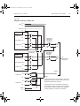
Card configuration — schematic................................................................. B-2
Document Number: 2701-900-01 Rev. F / August 2011
vii
2701-900-01.book Page viii Wednesday, August 3, 2011 9:43 AM
Table of Contents
Model 2701 Ethernet-Based DMM / Data Acquisition System
Connections and wiring .............................................................................. B-4
Screw terminals ................................................................................... B-4
Wiring procedure ................................................................................. B-6
Typical connections ............................................................................. B-8
Connection log................................................................................... B-10
C
D
Status and Error Messages ................................................................ C-1
Signal Processing Sequence and Data Flow ................................. D-1
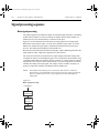
Signal processing sequence ...................................................................... D-2
Basic signal processing ....................................................................... D-2
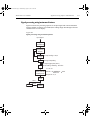
Signal processing using instrument features ....................................... D-3
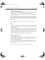
Signal processing using Ratio or Ch Avg............................................. D-6
Data flow (remote operation)...................................................................... D-7
SENSe and sample buffer ................................................................... D-8
[SENS[1]]:DATA[LATest]? .................................................................... D-9
[SENS[1]]:DATA:FRESh? .................................................................... D-9
FETCh? ............................................................................................. D-10
READ?............................................................................................... D-10
MEASure? ......................................................................................... D-10
CALC[1]:DATA[LATest]? .................................................................... D-10
CALC[1]:DATA:FRESh?..................................................................... D-10
CALC3:LIM1:FAIL?............................................................................ D-11
CALC3:LIM2:FAIL?............................................................................ D-11
TRACe:DATA? ................................................................................... D-11
CALC2:IMM? ..................................................................................... D-12
CALC2:IMM ....................................................................................... D-12
CALC2:DATA? ................................................................................... D-12
Continuous measurement mode........................................................ D-12
Scanning............................................................................................ D-13
E
Measurement Considerations ............................................................ E-1
Measurement considerations ..................................................................... E-2
Thermoelectric potentials..................................................................... E-2
Thermoelectric generation ................................................................... E-3
Minimizing thermal EMFs .................................................................... E-4
Source resistance noise ...................................................................... E-5
Magnetic fields..................................................................................... E-6
Radio frequency interference............................................................... E-6
Ground loops ....................................................................................... E-7
Shielding .............................................................................................. E-9
Meter loading ..................................................................................... E-10
viii
F
Temperature Equations .......................................................................
Thermocouple equation..............................................................................
Thermistor equation ...................................................................................
RTD equations ...........................................................................................
G
KE2700 Instrument Driver
Examples ....... G-1
Introduction................................................................................................. G-2
F-1
F-2
F-6
F-8
Document Number: 2701-900-01 Rev. F / August 2011
2701-900-01.book Page ix Wednesday, August 3, 2011 9:43 AM
Model 2701 Ethernet-Based DMM / Data Acquisition System
Table of Contents
Visual Basic and CVI (C) examples ........................................................... G-2
LabVIEW examples ................................................................................. G-12
Document Number: 2701-900-01 Rev. F / August 2011
ix
2701-900-01.book Page x Wednesday, August 3, 2011 9:43 AM
Table of Contents
x
Model 2701 Ethernet-Based DMM / Data Acquisition System
Document Number: 2701-900-01 Rev. F / August 2011
2701-900-01.book Page 1 Wednesday, August 3, 2011 9:43 AM
1
Getting Started
Quick Start — Of the following section topics, three can be used immediately to quickly
acquaint yourself with fundamental instrument operations. Use QS1 to familiarize yourself with front panel controls, use QS2 to power-up the instrument, and finally, use QS3 to
perform exercises to operate the instrument.
•
General information — Covers general information that includes contact information, safety symbols and terms, inspection, and available options and accessories.
•
Model 2701 features — Summarizes the features of Model 2701.
•
Plug-in switching modules — Summarizes the capabilities of the Keithley
Model 77xx series switching modules.
QS1 •
•
QS2 •
Front and rear panel familiarization — Summarizes the controls and connectors
of the instrument.
Rack mounting — Covers the options available for rack mounting the Model
2701 in a standard 19-inch rack.
Power-up — Covers line power connection, line voltage setting, fuse replacement,
power line frequency, and the power-up sequence.
•
Display — Provides information about the display of the Model 2701.
•
Defaults and user setups — Lists the *RST and factory default settings, and covers the three setup configurations available to the user.
•
Remote programming information — Explains how SCPI commands are presented in this manual.
2701-900-01.book Page 2 Wednesday, August 3, 2011 9:43 AM
1-2
Getting Started
QS3 •
Model 2701 User’s Manual
Quick start exercises — Provides abbreviated operating information and exercises (front panel and remote programming) to acquaint a user with operation
basics.
General information
Contact information
Worldwide phone numbers are listed at the front of this manual. If you have any questions,
please contact your local Keithley representative or call a Keithley Application Engineer
at 1-800-348-3735 (U.S. and Canada only).
Safety symbols and terms
The following symbols and terms may be found on the instrument or used in this manual:
The ! symbol on an instrument indicates that the user should refer to the operating
instructions located in the manual.
The
symbol on the instrument shows that high voltage may be present on the terminal(s). Use standard safety precautions to avoid personal contact with these voltages.
The WARNING heading used in this manual explains dangers that might result in
personal injury or death. Always read the associated information very carefully before
performing the indicated procedure.
The CAUTION heading used in this manual explains hazards that could damage the
instrument. Such damage may invalidate the warranty.
Inspection
Model 2701 was carefully inspected electrically and mechanically before shipment. After
unpacking all items from the shipping carton, check for any obvious signs of physical
damage that may have occurred during transit. (There may be a protective film over the
display lens, which can be removed). Report any damage to the shipping agent immediately. Save the original packing carton for possible future shipment. The following items
are included with every Model 2701 order:
•
•
•
•
•
•
•
•
Model 2701 with line cord.
Safety test leads (Model 1751).
Accessories as ordered.
Hardware for rack mounting.
Certificate of calibration.
Model 2701 User’s Manual - PDF on CD-ROM.
Model 2701 Instrument Networking Instruction Manual - Hard copy and PDF on
CD-ROM.
Model 2701 Getting started foldout.
2701-900-01.book Page 3 Wednesday, August 3, 2011 9:43 AM
Model 2701 User’s Manual
•
•
NOTE
Getting Started
1-3
Ethernet cross over cable (3-meters in length).
Software CD containing the following:
• TestPoint Runtime – Provides basic data logging capabilities. This can be
modified with the TestPoint application development package (optional
software).
• KE2700 IVI Instrument Driver – Provided for programmers, designed for use
with application development environments.
Optional “Software” available from Keithley is summarized on page 1-5.
The Model 2701 Service Manual is a separate purchased part. Contact
Keithley’s Service Department to order this manual.
Battery
The Model 2701 uses battery-backed memory for the 450,000 reading buffer. A fully
charged battery will maintain storage of readings for 30 days (at 23°C). At 50°C, the storage period is degraded to approximately 15 days. See Appendix A for specifications on
the rechargeable lithium ion battery.
The battery is warranted for 90 days. However, at 23°C, the battery will typically last three
years. See Section 3 of the Model 2701 Service Manual to replace the battery. The
Keithley part number for the battery is BA-52.
Options and accessories
Plug-in switching modules
NOTE
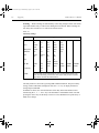
Table 1-1 provides a side-by-side comparison of the following Keithley switching modules. All multiplexer modules can be configured as two independent
multiplexers.
NOTE
The Model 77xx Series Switching Modules Instruction Manual provides operating and service information for the switching modules. This manual is supplied
with each switching module.
Model 7700 — This differential multiplexer provides 20 channels of 2-pole input or 10
channels of 4-pole input. The internal cold junction allows direct-connection of thermocouples. It also has two 2-pole channels used exclusively for current input.
Model 7701 — This differential multiplexer provides 32 channels of 2-pole input or 16
channels of 4-pole input.
Model 7702 — This differential multiplexer provides 40 channels of 2-pole input or
20 channels of 4-pole input. It also has two 2-pole channels used exclusively for current
input.
Model 7703 — This differential multiplexer provides 32 channels of 2-pole input or
16 channels of 4-pole input.
2701-900-01.book Page 4 Wednesday, August 3, 2011 9:43 AM
1-4
Getting Started
Model 2701 User’s Manual
Model 7705 — This control module provides 40 independent 1-pole switching (SPST)
channels that are isolated from the internal DMM.
Model 7706 — This all-in-one module provides 20/10 channels of 2/4-pole input,
16 digital outputs, two analog outputs, and one 32-bit counter with gating and totalizer.
Model 7707 — This module provides 10 channels of 2-pole input or 5 channels of 4-pole
input. Also provides four independent 8-byte digital I/O channels.
Model 7708 — This differential multiplexer provides 40 channels of 2-pole input or
20 channels of 4-pole input. The internal cold junction allows direct-connection of
thermocouples for temperature measurements.
Model 7709 — This module is configured as a 6 × 8 matrix (six rows, eight columns).
The matrix consists of 48 crosspoint channels and two backplane isolation channels. For
system channel operation, row 1 (8 channels) is connected to DMM Input. For 4-wire
measurements, rows 1 and 2 (4 system channels) are connected to the DMM.
Model 7710 — This differential multiplexer provides 20 channels of 2-pole input or
10 channels of 4-pole input. The internal cold junction allows direct-connection of
thermocouples for temperature measurements. This module provides high-speed
switching and uses long-life relays.
Model 7711 — The Model 7711 is a 50Ω, 2GHz, single-pole dual 1 × 4 RF Multiplexer
module (eight channels, no measurement capability). This 1 × 4 multiplexer is a cascading tree design — one of the channels of each is always connected to a common out. It can
be used to connect one instrument to multiple devices or multiple instruments to a single
device.
Model 7712 — The Model 7712 is a 50Ω, 3.5GHz, single-pole dual 1 × 4 RF Multiplexer
module (eight channels, no measurement capability). This 1 × 4 multiplexer is a cascading tree design — one of the channels of each is always connected to a common out. It can
be used to connect one instrument to multiple devices or multiple instruments to a single
device.
Cables and connector kits for switching modules
Model 7788 DB-50 connector kit — Contains two male DB-50 solder cup connectors
with strain relief connector shells. These connectors mate to the female connectors of the
Models 7703 and 7705 switching modules.
Model 7789 50/25-pin solder cup connector kit — Contains one male DB-50 and one
male DB-25 solder cup connectors. These connectors mate to the female connectors on the
Models 7701 and 7709 switching modules.
Model 7790 ribbon cable adapter kit — Contains one female DB-50, one male DB-50,
and one male DB-25 IDC ribbon cable connectors. These connectors are used with the
Models 7701, 7707, and 7709 switching modules.
Model 7051-X — BNC cable (male to male). 7051-2 is 2 ft long, 7051-5 is 5 ft long, and
7051-10 is 10 ft long. These cable are used with the Model 7711 switching module.
2701-900-01.book Page 5 Wednesday, August 3, 2011 9:43 AM
Model 2701 User’s Manual
Getting Started
1-5
Model 7712-SMA-1 — SMA cable (male to male), 1.0m (3.3 ft) long. This cable is used
with the Models 7711 and 7712 switching modules.
Model 7712-SMA-N — Female SMA to male N-type adapter. This adapter is used with
the Models 7711 and 7712 switching modules.
S46-SMA-X — SMA cable (male to male). S46-SMA-1 is one foot long and
S46-SMA-0.5 is one-half foot long. This cable is used with the Models 7711 and 7712
switching modules.
Cables and adapters (Ethernet, RS-232, and trigger link)
Ethernet cross over cable (3 meters) — Keithley P/N CA-180-3.
Models 8501-1 and 8501-2 trigger link cables — Connect Model 2701 to other instruments with Trigger Link connectors (e.g., Model 7002 Switch System). Model 8501-1 is
one meter long; Model 8501-2 is two meters long.
Model 8502 trigger link adapter — Lets you connect any of the two trigger link lines of
Model 2701 to instruments that use the standard BNC trigger connectors.
Model 8503 DIN to BNC trigger cable — Lets you connect trigger link lines one (Voltmeter Complete) and one (External Trigger) of Model 2701 to instruments that use BNC
trigger connectors. Model 8503 is one meter long.
Model 7009-5 shielded RS-232 cable — Five foot RS-232 cable with a male DB-9 connector on one end and a female DB-9 connector on the other end. Wired as a straight
through cable (not null modem).
Software
The following optional software is available from Keithley:
ExceLINX-1A – This is an economical, easy-to-use, add-in utility for Microsoft Excel ®
and Keithley Integra Series Multimeter/Switch systems. No programming is required.
Configure your measurements quickly using pop-up menus and eliminate time-consuming
and error prone programming. Acquire data into a spreadsheet on the fly during a scan or
transfer data into a spreadsheet after a scan is completed. A few mouse clicks are all it
takes to configure channels, set parameters, triggers, and scan lists. There is no need to
launch a separate data logging or data-crunching application; live data streams
automatically into an Excel workbook, ready for analysis or charting using all of Excel's
powerful built-in tools.
TestPoint application development package — This powerful and economical
programming environment uses object-oriented technology through a drag-and-drop
interface to build a basic system quickly and without in-depth programming. Optional
toolkits (database and statistical process control) are available to expand ExceLINX-1A
capability.
2701-900-01.book Page 6 Wednesday, August 3, 2011 9:43 AM
1-6
Getting Started
Model 2701 User’s Manual
Rack mount kits
Model 4288-1 single fixed rack mount kit — Mounts a single Model 2701 in a standard
19-inch rack.
Model 4288-2 side-by-side rack mount kit — Mounts two instruments (Models 182,
428, 486, 487, 2000, 2001, 2002, 2010, 2400, 2410, 2420, 2430, 2700, 2701, 6430,
6517A, 7001) side-by-side in a standard 19-inch rack.
Model 4288-4 side-by-side rack mount kit — Mounts Model 2701 and a 5.25-inch
instrument (Models 220, 224, 230, 263, 595, 614, 617, 775A, 6512) side-by-side in a
standard 19-inch rack.
Carrying case
Model 1050 padded carrying case — A carrying case for the Model 2701 includes
handles and shoulder strap.
Model 2701 features
Model 2701 is a 6½-digit high-performance multimeter/data acquisition system. It can
measure voltage (DC and AC), current (DC and AC), resistance (2- and 4-wire),
temperature (thermocouple, thermistor, and 4-wire RTD), frequency and period, and test
continuity.
The Model 2701 has two slots that will accommodate Keithley Model 7700 series switching modules (Table 1-1). Each channel of a switching module that is closed or scanned is
measured by the Model 2701. For scanning, each channel can have its own unique setup
(i.e., function, range, digits, etc.).
More information on the measurement capabilities of the Model 2701 is provided in
“DMM measurement capabilities,” page 3-2. A connection guide for the Model 7700 is
provided in Appendix B. Specifications for the Model 2701 and 7700 switching module
are provided in Appendix A.
Additional features of Model 2701 include:
•
•
•
•
•
•
Setup storage — Seven instrument setups (five user, *RST defaults, and factory
defaults) can be saved and recalled.
Offset-compensated ohms — A two-measurement process for 4-wire ohms to
cancel the effects of thermal EMFs. Available for the 100Ω, 1kΩ, and 10kΩ ranges.
Math — mX+b, percent, and reciprocal (1/X) calculations provide mathematical
manipulation of readings.
Relative — Null offsets or establish baseline values.
Ratio and channel average — Ratio and average calculations for two switching
module channels.
Buffer — Store up to 450,000 readings in the internal buffer.
2701-900-01.book Page 7 Wednesday, August 3, 2011 9:43 AM
Model 2701 User’s Manual
•
•
•
•
Getting Started
1-7
Limits — Two sets of high and low reading limits to test devices.
Digital I/O port — Five digital limit test output lines to control external circuitry.
The digital trigger link and hardware interlock input can also be accessed at this
port.
Monitor — The Model 2701 can monitor a selected channel. A scan can be triggered to start when the Monitor detects a reached reading limit.
Remote interface — Model 2701 can be controlled using the 10BaseT and
100BaseTX autosensing Ethernet or the RS-232 interface.
Plug-in switching modules
Up to two Keithley Model 77xx series switching modules can be installed in the
Model 2701. A side-by-side comparison of the switching modules is provided in
Table 1-1.
Basic close/open operation for switching module channels is provided in Section 2, while
scanning is covered in Section 7. Connection information for the Model 7700 switching
module is provided in Appendix B. For all other switching modules, connection information is provided in their respective packing lists.
NOTE
For maximum system performance, it is recommended that all measurement
cables be limited to less than 3 meters.
Pseudocards
Using remote programming, you can assign a pseudocard to an empty switching module
slot. With a pseudocard installed, the Model 2701 will operate as if the switching module
is installed in the Model 2701. This feature allows you to configure your system without
having the actual switching module installed in the unit. There is a pseudocard for every
Keithley Model 77xx series switching module. For details, see “Pseudocards,” page 2-6.
Identifying installed switching modules
On power-up, the model numbers of installed switching modules are displayed briefly. If a
Model 7700, 7701, 7702, 7703, 7705, 7708, 7709, 7710, 7711, or 7712 switching module
is removed while the Model 2701 is on, the instrument will operate as if the module is
installed. That is, the Model 2701 will operate as if the pseudocard is installed.
NOTE
If a Model 7706 or 7707 is removed while power is on, error +523 “Card hardware error” will occur, and the module will be removed from the system. In general, it is not recommended to install or remove switching modules with the
power on.
The CARD menu and remote query commands can be used to identify modules installed
in the mainframe. For details, see “Switching module installation and connections,”
page 2-4.
2701-900-01.book Page 8 Wednesday, August 3, 2011 9:43 AM
1-8
Getting Started
Model 2701 User’s Manual
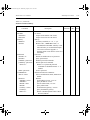
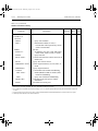
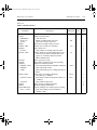
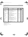
Table 1-1
Model 77xx series switching modules
Model 7700
2-pole Operation
4-pole Operation
1-pole Operation
Measure Volts
Measure Amps
Measure Ohms
Thermocouple
Cold Junction
Relay Type1
Connector type
Configuration2
Unique features
2-pole Operation
4-pole Operation
1-pole Operation
Measure Volts
Measure Amps
Measure Ohms
Thermocouple
Cold Junction
Relay Type1
Connector type
Configuration2
Unique features
Model 7701
Model 7702
Model 7703
20 channels
10 channel pairs
N/A
300V maximum
Ch 21 & 22, 3A Max
2/4-wire
Yes
32 channels
16 channel pairs
N/A
150V maximum
No
2/4-wire
No
40 channels
20 channel pairs
N/A
300V maximum
Ch 41 & 42, 3A Max
2/4-wire
No
32 channels
16 channel pairs
N/A
300V maximum
No
2/4-wire
No
Latching electromechanical
Oversized screw
terminals
Multiplexer
All DMM functions
Latching electromechanical
1 female DB-50
1 female DB-25
Multiplexer
All DMM functions
except amps
Latching electromechanical
Oversized screw terminals
Multiplexer
All DMM functions
Non-latching reed
Model 7705
Model 7706
Model 7707
N/A
N/A
40 channels
300V maximum
No
No
No
20 channels
10 channel pairs
N/A
300V maximum
No
2/4-wire
Yes
Latching electromechanical
2 female DB-50s
Latching electroLatching electromechanical
mechanical
Mini screw terminal 1 male DB-50
1female DB-25
Multiplexer
Multiplexer
Independent SPST
channels
Multiple channel
operation only
10 channels
5 channel pairs
N/A
300V
No
2/4-wire
No
2 female DB-50s
Multiplexer
All DMM functions
except amps
Model 7708
40 channels
20 channel pairs
N/A
300V maximum
No
2/4-wire
Yes
Latching electromechanical
Oversized screw
terminals
Multiplexer
16 digital outputs, 2 32 digital inputs/out- All DMM functions
analog outputs, one puts
except amps
counter/totalizer
2701-900-01.book Page 9 Wednesday, August 3, 2011 9:43 AM
Model 2701 User’s Manual
Getting Started
1-9
Table 1-1 (continued)
Model 77xx series switching modules
2-pole Operation
4-pole Operation
1-pole Operation
Measure Volts
Measure Amps
Measure Ohms
Thermocouple
Cold Junction
Relay Type1
Connector type
Configuration2
Unique features
Models 7711
and 7712
Model 7709
Model 7710
8-channels
4 channel pairs
N/A
300V maximum
No
2/4-wire
No
20 channels
10 channel pairs
N/A
60V maximum
No
2/4-wire
Yes
N/A
N/A
8 channels
No3
No3
No3
No3
Latching electromechanical
1 female DB-50
1 female DB-25
6 x 8 matrix
Rows 1 & 2 connect
to DMM (system
channel operation)
Solid state opto-coupled FET
3.5mm removable
screw terminals
Multiplexer
High-speed switching and long-life
relays
High frequency
electromechanical
10 SMA
Multiplexer
50Ω RF dual 1 x 4
multiplexer
Max Frequency:
7711: 2GHz
7712: 3.5GHz
1. Latching relays hold their open/close state after the mainframe is turned off. When turned on, all relays open after a few
seconds.
2. All multiplexers can be configured as two independent multiplexers.
3. The Models 7711 and 7712 have no measurement capabilities.
2701-900-01.book Page 10 Wednesday, August 3, 2011 9:43 AM
1-10
Getting Started
Model 2701 User’s Manual
Front and rear panel familiarization
(QS1)
Front panel summary
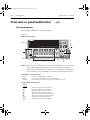
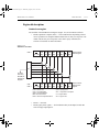
The front panel of Model 2701 is shown in Figure 1-1.
Figure 1-1
Model 2701 front panel
INTEGRA SERIES
SENSE
Ω4 WIRE
INPUT
HI
4
350V
PEAK
1000V
PEAK
!
7
2701 ETHERNET MULTIMETER / DATA ACQUISITION SYSTEM
MATH O U T P U T
SHIFT
DCV
DELAY
LOCAL
1
POWER
ACV
HOLD
EX TRIG TRIG
SAVE
SETUP
OPEN CLOSE
RATIO
DCI
LIMITS
CH AVG
CONT
ACI
Ω2
ON/OFF
STORE RECALL
CONFIG
HALT
STEP
SCAN
TYPE
OCOMP
Ω4
FREQ
MONITOR
CH-OFF
FILTER
REL
TEST
LSYNC
DIGITS RATE
LO
PERIOD SENSOR
500V
PEAK
INPUTS
TEMP
RANGE
F
R
CARD
AUTO
FRONT/REAR
3A 250V
ETHERNET RS-232
EXIT
RANGE
AMPS
CAT I
ENTER
6
2
NOTE
3
5
Most keys provide a dual function or operation. The nomenclature on a key indicates its unshifted function/operation which is selected by pressing the key.
Nomenclature (in blue) above a key indicates its shifted function. A shifted function is selected by pressing the SHIFT key and then the function/operation key.
1 Special keys and power switch:
SHIFT
LOCAL
POWER
Use to select a shifted function or operation.
Cancels remote mode. SHIFT + LOCAL disables keyclick.
Power switch. In position turns 2701 on (I), out position turns it off (O).
2 Function and operation keys:
Top Row
Unshifted
DCV
ACV
DCI
ACI
Ω2
Ω4
FREQ
TEMP
Selects DC voltage measurement function.
Selects AC voltage measurement function.
Selects DC current measurement function.
Selects AC current measurement function.
Selects 2-wire resistance measurement function.
Selects 4-wire resistance measurement function.
Selects frequency measurement function.
Selects temperature measurement function.
2701-900-01.book Page 11 Wednesday, August 3, 2011 9:43 AM
Model 2701 User’s Manual
Shifted
MATH
OUTPUT
RATIO
CH-AVG
CONT
OCOMP
PERIOD
SENSOR
Middle Row
Unshifted
EXTRIG
TRIG
STORE
RECALL
FILTER
REL
and
Shifted
DELAY
HOLD
LIMITS
ON/OFF
TYPE
MONITOR
CH-OFF
CARD
Bottom Row
Unshifted
OPEN
CLOSE
STEP
SCAN
DIGITS
RATE
EXIT
ENTER
Shifted
SAVE
SETUP
CONFIG
HALT
TEST
LSYNC
ETHERNET
RS-232
Getting Started
1-11
Configures and controls mX+b, percent, or reciprocal (1/X) calculation.
Configures and controls digital and audio (beeper) output for limits.
Enables/disables channel ratio.
Enables/disables channel average.
Configures and controls continuity test.
Enables/disables offset compensated ohms with Ω4 function selected.
Selects period measurement function.
Configures temperature measurements.
Selects external triggering as the trigger source.
Triggers a measurement when in external triggering (EX TRIG).
Sets the number of readings to store and enables the buffer.
Displays stored readings and buffer statistics. Use the , , , and keys to navigate
through buffer.
Enables/disables filter for selected function.
Enables/disables relative for selected function.
Dual function—Manually scans switching channels. When in a menu, these keys control
cursor position for making selections or change values.
Sets user delay between trigger and measurement.
Holds reading when the selected number of samples is within the selected tolerance.
Sets upper and lower limits for readings.
Enables/disables limits.
Configures and enables filter for selected function.
Selects and enable/disables monitor channel.
Disables channel for a scan (must be in scan channel setup mode).
Identifies switching modules installed in mainframe. Set up switching modules that require
configuration. View closed channels and channel settings for switching modules that
require configuration.
Opens closed channel.
Closes specified channel.
Steps through channels; sends a trigger after each channel.
Scans through channels; sends a trigger after last channel.
Sets display resolution for all functions.
Sets measurement speed (fast, medium, or slow) for all functions.
Cancels selection, moves back to measurement display.
Accepts selection, moves to next choice or back to measurement display.
Saves up to five instrument setups for future recall, and selects power-on setup.
Restores a default setup (factory or *RST) or a saved setup. Enables/disables buffer auto
clear, auto scan, and auto channel configuration. Sets timestamp, date, and time. Displays
serial number of Model 2701.
Selects and configures a simple scan or an advanced scan.
Disables step/scan.
Selects the calibration menu, display test or the key-press test.
Enables/disables line cycle synchronization. When enabled, noise induced by the power
line is reduced at the expense of speed.
Enables/disables and configures Ethernet settings.
Enables/disables RS-232 interface; selects baud rate, flow control, and terminator.
2701-900-01.book Page 12 Wednesday, August 3, 2011 9:43 AM
1-12
Getting Started
Model 2701 User’s Manual
3 Range keys:
Unshifted
and
AUTO
Dual function—Selects the next higher/lower measurement range for the selected function.
When in a menu, these keys make selections or change values.
Enables/disables autorange for the selected function.
4 Display annunciators:
* (asterisk)
↔ (more)
))) (speaker)
4W
~AC
AUTO
BUFFER
CHAN
DELTA
ERR
FAST
FILT
HIGH
HOLD
LOW
MATH
MED
MON
OCOMP
RATIO
REAR
REL
REM
SCAN
SHIFT
SLOW
SRQ
STAT
STEP
TIMER
TRIG
Readings being stored in buffer.
Indicates additional selections are available.
Beeper on for continuity or limits testing.
Digital input/output or analog output active (set to non-default value).
4-wire resistance or 4-wire RTD temperature reading displayed.
AC function selected (ACV, dB, or ACI).
Auto range enabled.
Recalling readings stored in buffer.
Setup or reading for a switching channel displayed.
Channel average enabled.
Questionable reading or invalid cal step.
Fast reading rate selected.
Filter enabled for selected function.
Reading has reached or exceeded the enabled high limit.
2701 in hold mode.
Reading has reached or exceeded the enabled low limit.
mX+b, percent, or reciprocal (1/X) calculation enabled.
Medium reading rate selected.
Monitor channel displayed.
4-wire offset compensated ohms enabled.
Channel ratio enabled.
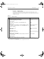
Front panel input terminals disconnected.
Relative enabled for selected function.
Instrument in Ethernet remote mode.
Scanning operation being performed.
Accessing a shifted key.
Slow reading rate selected.
Service request over Ethernet or RS-232.
Displaying buffer statistics.
Stepping operation being performed.
Timer controlled triggering in use.
External triggering selected.
5 INPUTS switch:
Use to select front panel inputs (out; F) position or switching module inputs (in; R) position.
NOTE
For remote programming, the following command queries the INPUTS switch
position:
SYSTem:FRSWitch?
' Query INPUTS switch; 0 = rear, 1 = front.
6 Handle:
Pull out and rotate to desired position.
2701-900-01.book Page 13 Wednesday, August 3, 2011 9:43 AM
Model 2701 User’s Manual
Getting Started
1-13
7 Front panel inputs:
INPUT HI and LO
SENSE HI and LO
AMPS
Amps fuse holder
Used for DCV, ACV, Ω2, CONT, FREQ, PERIOD, and thermocouple/thermistor
TEMP measurements.
Use with INPUT HI and LO for Ω4 and RTD TEMP measurements.
Use with INPUT LO for DCI and ACI measurements.
Holds current fuse for front panel amps input.
Rear panel summary
The rear panel of Model 2701 is shown in Figure 1-2. As shown, a slot cover is installed
on slot 2.
Figure 1-2
Model 2701 rear panel
1
2
4
3
WARNING:NO INTERNAL OPERATOR SERVICABLE PARTS,SERVICE BY QUALIFIED PERSONNEL ONLY.
Link/Act
100bT
CAT I
!
DIGITAL I/O
(EXT. TRIG.)
TRIGGER
LINK
ETHERNET
10/100 BaseT
MADE IN
U.S.A.
RS-232
~LINE RATING
50, 60, 400Hz
80VA MAX
SLT
1
FUSE
250mAT
6
LINE
100V
120V
125mAT 220V
240V
KEITHLEY
SLOT COVER
SLT
2
CAUTION:FOR CONTINUED PROTECTION AGAINST FIRE HAZARD,REPLACE FUSE WITH SAME TYPE AND RATING.
!
5
2701-900-01.book Page 14 Wednesday, August 3, 2011 9:43 AM
1-14
Getting Started
Model 2701 User’s Manual
1 DIGITAL I/O (EXT. TRIG.)
Male DB-9 connector for digital input (trigger link in) and digital outputs.
2 TRIGGER LINK
Eight-pin micro-DIN connector for sending and receiving trigger pulses among connected instruments. Use a
trigger link cable or adapter, such as Models 8501-1, 8501-2, 8502, and 8503.
3 ETHERNET
RJ45 female connector for Ethernet operation. Use an RJ45 male/male cable for connection. Two status LEDs
are located at the top of the connector. These LEDs indicate the status of the Ethernet (see Section 10, “Ethernet
connections”).
4 RS-232
Female DB-9 connector for RS-232 operation. Use a straight-through (not null modem) DB-9 shielded cable.
5 Power module
Contains the AC line receptacle, power line fuse, and line voltage setting. The instrument can be configured
for line voltages of 100V/120V/220V/240VAC at line frequencies of 50 or 60Hz.
6 Slot 1 and Slot 2
Two slots to accommodate Keithley Model 77xx series switching modules. The Model 2701 is shipped from
the factory with slot covers installed. Please note additional slot covers can be requested from
Keithley Instruments.
WARNING
Slot covers must be installed on unused slots to prevent personal contact with high voltage circuits.
2701-900-01.book Page 15 Wednesday, August 3, 2011 9:43 AM
Model 2701 User’s Manual
Power-up
Getting Started
1-15
(QS2)
The Model 2701 will operate properly using the following line power voltages and
frequencies:
•
•
Line power voltages – 100V, 120V, 220V, and 240V.
Line power frequencies – 45Hz to 66Hz and 360Hz to 440Hz.
Line power connection
Follow the procedure below to connect the Model 2701 to line power and turn on the
instrument.
1.
Check to see that the line voltage indicated in the window of the fuse holder assembly (Figure 1-3) is correct for the operating voltage in your area. If not, refer to
“Setting line voltage and replacing fuse,” page 1-16.
CAUTION
2.
3.
Before plugging in the power cord, make sure that the front panel power switch is
in the off (O) position.
Connect the female end of the supplied power cord to the AC receptacle on the rear
panel. Connect the other end of the power cord to a grounded AC outlet.
WARNING
4.
Operating the instrument on an incorrect line voltage may cause damage to the instrument, possibly voiding the warranty.
The power cord supplied with the Model 2701 contains a separate
ground wire for use with grounded outlets. When proper connections
are made, instrument chassis is connected to power line ground
through the ground wire in the power cord. Failure to use a grounded
outlet may result in personal injury or death due to electric shock.
Turn on the instrument by pressing the front panel power switch to the on (I)
position.
2701-900-01.book Page 16 Wednesday, August 3, 2011 9:43 AM
1-16
Getting Started
Model 2701 User’s Manual
Figure 1-3
Power module
Model 2701
WARNING:NO INTERNAL OPERATOR SERVICABLE PARTS,SERVICE BY QUALIFIED PERSONNEL ONLY.
Link/Act
100bT
CAT I
!
DIGITAL I/O
(EXT. TRIG.)
TRIGGER
LINK
ETHERNET
10/100 BaseT
MADE IN
U.S.A.
RS232
SLT
1
~LINE RATING
50, 60, 400Hz
80VA MAX
FUSE
250mAT
!
LINE
100V
120V
Fuse
125mAT 220V
240V
KEITHLEY
SLOT COVER
SLT
2
Line
Voltage
Selector
CAUTION:FOR CONTINUED PROTECTION AGAINST FIRE HAZARD,REPLACE FUSE WITH SAME TYPE AND RATING.
100
220
240
120
Spring
Window
Fuse Holder Assembly
Line frequency
The Model 2701 will operate at line frequencies from 45Hz to 66Hz and 360Hz to 440Hz.
There are no user-settings for line frequency. It is automatically sensed at power-up. The
following command can be used to read the line frequency:
SYSTem:LFRequency?
' Query power line frequency.
Setting line voltage and replacing fuse
A rear panel fuse located next to the AC receptacle protects the power line input of the
instrument. If the line voltage setting needs to be changed or the line fuse needs to be
replaced, perform the following steps.
WARNING
1.
Make sure the instrument is disconnected from the AC line and other
equipment before changing the line voltage setting or replacing the
line fuse.
Place the tip of a flat-blade screwdriver into the power module by the fuse holder
assembly (Figure 1-3). Gently push in and up. Release pressure on the assembly
and its internal spring will push it out of the power module.
2701-900-01.book Page 17 Wednesday, August 3, 2011 9:43 AM
Model 2701 User’s Manual
2.
Getting Started
1-17
Remove the fuse and replace it with the type listed in Table 1-2.
CAUTION
3.
For continued protection against fire or instrument damage, only
replace fuse with the type and rating listed. If the instrument repeatedly blows fuses, locate and correct the cause of the trouble before
replacing the fuse.
If configuring the instrument for a different line voltage, remove the line voltage
selector from the assembly and rotate it to the proper position. When the selector is
installed into the fuse holder assembly, the correct line voltage appears sideways in
the window.
Install the fuse holder assembly into the power module by pushing it in until it
locks in place.
4.
Table 1-2
Fuse ratings
Line voltage
100/120V
220/240V
Fuse rating
0.630A, 250V, 5 × 20 mm, slow-blow
0.315A, 250V, 5 × 20 mm, slow-blow
Keithley P/N
FU-106-.630
FU-106-.315
Power-up sequence
NOTE
If a problem develops while the instrument is under warranty, return it to
Keithley Instruments, Inc., for repair. A short description of any displayed error
messages are provided in Appendix C.
NOTE
The entire power-up cycle takes approximately 30 seconds. Do not attempt to
communicate with the Model 2701 during this time period.
Turn on the Model 2701 by pressing in the front panel POWER button. While booting up,
the following messages will be briefly displayed:
LOADING FPGA
LOADING MAIN
If Ethernet is the presently selected interface, the following will be displayed for 10 to 15
seconds:
LOAD ETHRNET
2701-900-01.book Page 18 Wednesday, August 3, 2011 9:43 AM
1-18
Getting Started
Model 2701 User’s Manual
The instrument then briefly displays all display characters and annunciators, and performs
self-tests. If all self-tests pass, the firmware revision levels are displayed. An example of
this display is:
REV: A01 A01
where: First A01 is the main board ROM revision.
Second A01 is the display board ROM revision.
If Ethernet is the presently selected interface, the IP address will be displayed briefly.
Example:
ETHERNET
192.168.000.002
If RS-232 is the presently selected interface, the baud rate will be displayed briefly:
RS-232 MODE
BAUD: 9600
Installed switching modules are then displayed. For example, if there is a Model 7700
switching module installed in both slots, the following messages will be displayed:
1: 7700
2: 7700
If a slot is empty, the message “NONE” will be displayed instead.
If the saved power-on setup is not the factory defaults setup (SYSTem:POSetup PRESet),
a message to identify the setup will be briefly displayed (“Defaults and user setups,”
page 1-21).
After the power-up sequence, the instrument begins its normal display of readings.
NOTE
The serial number of the Model 2701 can be displayed by selecting the SNUM
item of the SETUP menu. Press SHIFT and then SETUP to access the menu. For
remote operation, the serial number can be read using the *IDN? command (see
Section 12 for details).
NOTE
The serial number and revision levels can be accessed from the internal web
page of the Model 2701 using the Internet Explorer. For details, see “Internal
web page” in Section 10.
2701-900-01.book Page 19 Wednesday, August 3, 2011 9:43 AM
Model 2701 User’s Manual
Getting Started
1-19
Keyclick
With keyclick enabled, an audible click will sound when a front panel key is pressed. Perform the following steps to disable or enable keyclick:
1.
2.
Press SHIFT and then LOCAL to display the present state of KEYCLICK (ON or
OFF).
Press or to display the desired keyclick state and press ENTER.
Remote programming
The following command controls keyclick:
SYSTem:KCLick <b>
' Enable or disable keyclick.
where: <b> = ON or OFF
NOTE
Keyclick ON is the FACTORY, *RST, and SYSTem:PRESet default.
Display
Readings are displayed in engineering units (i.e., 100.23mV), while annunciators indicate
various states of operation. See “Front panel summary,” page 1-10, for a complete listing
of display annunciators.
NOTE
The display test allows you to test display digit segments and annunciators. The
key test checks the functionality of front panel keys. These tests are accessed by
pressing SHIFT and then TEST. Refer to the Model 2701 Service Manual for
details.
Status and error messages
Status and error messages are displayed momentarily. During operation and programming,
you will encounter a number of front panel messages. Typical messages are either of status
or error variety, as listed in Appendix C.
Remote programming — display
Using remote programming, the Model 2701 can display a custom ASCII message (up to
12 characters). Also, the front panel display and controls can be disabled.
Display commands
The commands are listed in Table 1-3. Details on these commands follow the table.
2701-900-01.book Page 20 Wednesday, August 3, 2011 9:43 AM
1-20
Getting Started
NOTE
Model 2701 User’s Manual
Optional command words and queries are not included in Table 1-3. Table 15-2
provides an unabridged list of all display commands.
Table 1-3
Display commands
Command
Description
DISPlay:TEXT:DATA <a> Define message (<a> = ASCII characters,
up to 12).
DISPlay:TEXT:STATe <b> Enable or disable message mode (<b> = ON
or OFF).
DISPlay:ENABle <b>
Enable or disable the front panel display
(<b> = ON or OFF).
Default*
(none)
OFF
ON
*SYSTem:PRESet and *RST have no effect on DISPlay commands. The listed defaults are power-on defaults.
DISPlay:TEXT:DATA <a>
Define text message
This command defines the text message for display. A message can be as long as 12 characters. A space counts as a character. Excess message characters results in an error. The
characters must be enclosed in either single quotes (‘ ’) or double quotes (“ ”).
DISPlay:TEXT:STATe ON | OFF
Control (on/off) message for display
This command enables and disables the text message mode. When enabled, a defined
message is displayed. When disabled, the message is removed from the display.
A user defined text message remains displayed only as long as the instrument is in remote.
Taking the instrument out of remote (by pressing the LOCAL key or sending GTL) cancels the message and disables the text message mode.
DISPlay:ENABle ON | OFF
Control display circuitry
This command is used to enable and disable the front panel display circuitry. When disabled, the instrument operates at a higher speed. While disabled, the display is blanked.
All front panel controls (except LOCAL) are disabled. Normal display operation can be
resumed by using the ENABle command to enable the display or by putting the
Model 2701 into local mode (press LOCAL).
Programming example
The following command sequence displays the text message “TESTING”:
DISP:TEXT:DATA 'TESTING'
DISP:TEXT:STAT ON
' Define text message.
' Enable text message mode.
2701-900-01.book Page 21 Wednesday, August 3, 2011 9:43 AM
Model 2701 User’s Manual
Getting Started
1-21
Defaults and user setups
Model 2701 can be restored to one of two default setup configurations (FACTory or
*RST) or five user-saved (SAV0, SAV1, SAV2, SAV3, or SAV4). As shipped from the
factory, Model 2701 powers up to the factory (FACT) default settings.
NOTE
Closed channels can be saved in a user setup (SAV0, SAV1, SAV2, SAV3 or
SAV4). When the setup is restored, those channels (and only those channels) will
be closed. FACT and *RST defaults opens all channels.
The factory default setup provides continuous triggering, while the *RST default setup
places the Model 2701 in the one-shot trigger mode. With one-shot triggering, a measurement is performed whenever the TRIG key is pressed or an initiate command is sent over
the remote interface.
The factory and *RST default settings are listed in Table 1-4. Setting differences (Set Diff)
between the two default setups are indicated by checkmarks ( ).
For remote programming, the SYSTem:PRESet and *RST commands are used to reset the
instrument. The *RST command returns the instrument to the *RST defaults and, for the
most part, the SYSTem:PRESet command returns the instrument to the factory default
conditions. The exceptions are explained as follows:
•
•
Auto scan and auto channel configuration — FACTory defaults disable auto scan
and auto channel configuration, while SYSTem:PRESet has no effect. The *RST
defaults (front panel and remote operation) have no effect.
Memory buffer auto clear — FACTory defaults enable buffer auto clear, while
SYSTem:PRESet has no effect. The *RST defaults (front panel and remote operation) have no effect.
The instrument will power up to whichever default setup is saved as the power-on setup.
NOTE
At the factory, the factory default setup is saved as the SAV0, SAV1, SAV2, SAV3,
or SAV4 setup.
Saving and restoring setups
Saving a user setup
1.
2.
3.
4.
Configure Model 2701 for the desired measurement application.
Press SHIFT and then SAVE to access the save setup menu.
Press to place the cursor on the present setup (SAV0, SAV1, SAV2, SAV3,
SAV4).
Use the or key to display the desired setup and press ENTER. The instrument
returns to the normal measurement state.
2701-900-01.book Page 22 Wednesday, August 3, 2011 9:43 AM
1-22
Getting Started
Model 2701 User’s Manual
WARNING
If you make firmware upgrades you will lose all your saved settings.
Saving a power-on setup
1.
2.
3.
4.
5.
Configure Model 2701 for the desired measurement application.
Press SHIFT and then SAVE to access the save setup menu.
Press the key to display the present power-on (PWR-ON) setup; FACT, *RST,
SAV0, SAV1, SAV2, SAV3, or SAV4.
Press to place the cursor on the present power-on setup.
Use the or key to display the desired setup and press ENTER. The instrument
returns to the normal measurement state.
Restoring a setup
1.
2.
3.
NOTE
Press SHIFT and then SETUP to access the restore setup menu.
Press to place the cursor on the present RESTORE setup (FACT, *RST, SAV0,
SAV1, SAV2, SAV3, or SAV4).
Use the or key to display the desired setup and press ENTER. The instrument
returns to the normal measurement state.
If the settings for a user setup or power-on setup do not match the switching
module types presently installed in the Model 2701, error +520 (Saved setup
scancard mismatch) occurs when the setup is recalled. The scan list will reset to
the factory defaults and all channels will open. However, the saved setup is still
retained in memory and can be restored when the matching switching module is
later installed.
2701-900-01.book Page 23 Wednesday, August 3, 2011 9:43 AM
Model 2701 User’s Manual
Getting Started
1-23
Table 1-4
Default settings
Setting
Auto channel configuration
Autozero
Buffer
Auto clear
Channel Average
Closed channels
Closure count interval
Continuity
Beeper
Digits
Range
Rate
Threshold level
Current (AC and DC)
Bandwidth (AC)
Digits (AC)
Digits (DC)
Filter
Window
Count
Type
Range
Rate (DC)
Rel
Ethernet settings:
IP address
Subnet
Gateway
MAC
Frequency and Period
Digits
Range
Rate (aperture)
Rel
Function
Keyclick
Factory
*RST
No (off)
On
No effect
Yes (on)
Off
None
No effect
No effect
On
No effect
No effect
Off
None
No effect
On
4½ digits
1kΩ
Fast (0.01 PLC)
10Ω
On
4½ digits
1kΩ
Fast (0.01 PLC)
10Ω
30
5½ digits
6½ digits
On
0.1%
10
Moving
Auto
Slow (5 PLC)
Off
30
5½ digits
6½ digits
Off
0.1%
10
Repeat
Auto
Slow (5 PLC)
Off
No effect
No effect
No effect
No effect
No effect
No effect
No effect
No effect
6½ digits
10V
1 second
Off
DCV
On
6½ digits
10V
1 second
Off
On
Set Diff
2701-900-01.book Page 24 Wednesday, August 3, 2011 9:43 AM
1-24
Getting Started
Model 2701 User’s Manual
Table 1-4 (continued)
Default settings
Setting
Limits
LO Limit 1
HI Limit 1
LO Limit 2
HI Limit 2
Line Synchronization
Math
mX+B
Scale Factor
Offset
Units
Percent
Reference
1/X (Reciprocal)
Monitor
Output
Beeper
Digital Output
Logic Sense
Pulse
Ratio
Resistance (Ω2 and Ω4)
Digits
Filter
Window
Count
Type
Offset compensation (OCOMP)
Range
Rate
Rel
Factory
*RST
Off
-1
+1
-2
+2
Off
Off
-1
+1
-2
+2
Off
Off
1.0
0.0
“X”
Off
1.0
Off
Off
Off
1.0
0.0
“X”
Off
1.0
Off
Off
Never
Off
High
No (off)
Off
Never
Off
High
No (off)
Off
6½ digits
On
0.1%
10
Moving
Off
Auto
Slow (5 PLC)
Off
6½ digits
Off
0.1%
10
Repeat
Off
Auto
Slow (5 PLC)
Off
Set Diff
2701-900-01.book Page 25 Wednesday, August 3, 2011 9:43 AM
Model 2701 User’s Manual
Getting Started
1-25
Table 1-4 (continued)
Default settings
Setting
RS-232
Baud rate
Flow control
Terminator
Scanning
Auto scan
Type (Simple or Advanced)
Simple scan
Minimum channel
Maximum channel
Timer
Reading count
Advanced scan
Setup
Immediate trigger
Limit triggers
Timer
Reading count
Temperature
Digits
Filter
Window
Count
Type
Rate
Rel
Sensor
Junction
Open detector
Type
Units
Timestamp
Triggering
Delay
Source
Reading hold
Window
Count
Factory
*RST
No effect
No effect
No effect
No effect
Disabled
No (off)
No effect
No effect
No effect
No effect
No effect
Disabled
No effect
No effect
101, 201, 301, 401, or 501
No effect
Off
No effect
101, 201, 301, 401, or 501
No effect
Off
No effect
No effect
On
Off
Off
No effect
No effect
On
Off
Off
No effect
5½ digits
On
0.1%
10
Moving
Slow (5 PLC)
Off
Thermocouple
See Note
No (off)
K
°C
No effect
Continuous
Auto
Immediate
Off
1%
5
5½ digits
Off
0.1%
10
Repeat
Slow (5 PLC)
Off
Thermocouple
See Note
No (off)
K
°C
No effect
One-shot
Auto
Immediate
Off
1%
5
Set Diff
2701-900-01.book Page 26 Wednesday, August 3, 2011 9:43 AM
1-26
Getting Started
Model 2701 User’s Manual
Table 1-4 (continued)
Default settings
Setting
Factory
Voltage (AC and DC)
dB
Reference
Digits (AC)
Digits (DC)
Filter
Window
Count
Type
Range
Rate (DC)
Rel
Off
1.0
5½ digits
6½ digits
On
0.1%
10
Moving
Auto
Slow (5 PLC)
Off
*RST
Set Diff
Off
1.0
5½ digits
6½ digits
Off
0.1%
10
Repeat
Auto
Slow (5 PLC)
Off
Note: With a Model 7700, 7706, or 7708 installed, the default sensor junction is Internal. Otherwise, the Simulated (23ºC) junction is
selected.
Remote programming — default and user setups
Default and user setup commands are listed in Table 1-5.
NOTE
The SYSTem:PRESet and *RST defaults are listed in the SCPI tables in
Section 15.
Table 1-5
Default setup commands
Commands
Description
SYSTem:PRESet
*RST
Restore SYSTem:PRESet defaults.
Restore *RST defaults.
*SAV <NRf>
*RCL <NRf>
Save settings as user setup; <NRf> = 0, 1, 2, 3, or 4.
Restore user saved setup; <NRf> = 0, 1, 2, 3, or 4.
SYSTem:POSetup <name>
Specify power-on setup; <name> = RST, PRESet, SAV0,
SAV1, SAV2, SAV3, or SAV4.
Programming example
*SAV 2
SYST:POS SAV2
*RST
*RCL 2
'
'
'
'
Save present setup in memory location 2.
Specify SAV2 setup as the power-on setup.
Return 2701 to RST defaults.
Return 2701 to setup stored in memory location 2.
2701-900-01.book Page 27 Wednesday, August 3, 2011 9:43 AM
Model 2701 User’s Manual
Getting Started
1-27
Remote programming information
Remote programming information is integrated with front panel operation throughout this
manual. Programming commands are listed in tables, and additional information that
pertains exclusively to remote operation is provided after each table. The tables may
reference you to other sections of this manual.
NOTE
Except for Section 11 through Section 15, most programming tables in this manual are abridged. That is, they exclude most optional command words and query
commands. Optional command words and query commands are summarized as
follows.
Optional command words — In order to be in conformance with the IEEE-488.2 standard, Model 2701 accepts optional command words. Any command word that is enclosed
in brackets ([]) is optional and does not have to be included in the program message.
Query commands — Most command words have a query form. A query command is
identified by the question mark (?) that follows the command word. A query command
requests (queries) the programmed status of that command.
NOTE
For complete details, see “Programming syntax,” page 10-21.
2701-900-01.book Page 28 Wednesday, August 3, 2011 9:43 AM
1-28
Getting Started
Model 2701 User’s Manual
Quick start exercises
(QS3)
This section topic summarizes the following basic instrument operations and provides
simple exercises to perform them:
•
•
•
•
NOTE
Basic DMM measurements — front panel inputs.
Closing and opening channels — system channel operation.
Simple scanning.
Trigger and return readings — remote programming.
For remote operations, you can use the internal web page of the Model 2701 to
send commands, queries, and take readings. See “Internal web page” in
Section 10 for details.
Also, supplied TestPoint Runtime start-up software can be used to control the
Model 2701. See Section 4 in the Model 2701 Instrument Networking Instruction
Manual for details
WARNING
NOTE
For the exercises, it is not necessary to connect an input signal or DUT
to the instrument (front panel inputs or switching module inputs).
However, if you decide to use an input signal, it is recommended that
you keep it at a nonhazardous level (<42V) while learning to use the
instrument.
When using the front panel input terminals, the INPUT switch must be in the
“F” (out) position. The INPUT switch is located on the right side of the front
panel near the input terminals. When using a switching module, the switch must
be in the “R” (in) position.
2701-900-01.book Page 29 Wednesday, August 3, 2011 9:43 AM
Model 2701 User’s Manual
Getting Started
1-29
Basic DMM measurements — front panel inputs
NOTE
See Section 3 for details on basic DMM operation.
The Model 2701 is shipped from the factory to power-up to factory defaults. The instrument powers up to a setup that continuously measures DC volts. Some of the default settings for the DCV function include auto range enabled, 6½-digit resolution, filter enabled,
and slow reading rate. These settings provide a good starting point and in many cases, do
not need to be changed.
“Starting-point” default settings are also provided for the other measurement functions.
Therefore, to perform basic measurements, simply select the desired function, and
“tweak” the setup (range, rate, filter, digits, etc.) as required.
For remote programming, the instrument is typically used in a non-continuous measurement mode. In this mode, the user (via remote command programming) specifies the number of measurements to perform. *RST defaults place the instrument in a non-continuous
measurement mode. Most of the other settings for factory and *RST defaults are the same.
For remote programming, the following command is used to select function.
NOTE
Items in brackets ([]) are optional and do not need to be included. Upper case
characters are required. Lower case characters are optional and need not be
included.
[SENSe[1]]:FUNCtion <func>
<func> ='VOLTage[:DC]'
'VOLTage:AC'
'CURRent[:DC]'
'CURRent:AC'
'RESistance'
'FRESistance'
'FREQuency'
'PERiod'
'TEMPerature'
'Select measurement function.'
DCV
ACV
DCI
ACI
Ω2
Ω4
FREQ
PERIOD
TEMP
Each function can have its own unique setup configuration (i.e., range, digits, speed, etc.).
For example, the following command words select range and digits:
RANGe[:UPPer] <n> ' Specify expected reading.
RANGe:AUTO <b>
' Enable (ON) or disable (OFF) auto range.
DIGits
' Set display resolution; 3.5, 4.5, 5.5, or 6.5 (digits).
The following examples demonstrate how to include the function name in the command
string for configuration commands.
VOLT:RANG 10
RES:RANG:AUTO ON
CURR:DIG 4.5
NOTE
'
'
'
Select 10V range for DCV.
Enable auto range for Ω2.
Set DCI for 4½-digit resolution.
See Section 4 for details on setting range, digits, rate, bandwidth, and filter.
2701-900-01.book Page 30 Wednesday, August 3, 2011 9:43 AM
1-30
Getting Started
Model 2701 User’s Manual
Exercise 1 — Basic DMM measurements
The exercise in Table 1-6 measures ACV on the 10V range and stores 15 readings in the
buffer.
Table 1-6
Exercise 1—Measure AC volts - store readings in buffer
Front panel operation
1
2
3
4
6
Command sequence
For front panel operation, proceed to step 2.
For remote programming, clear the buffer1:
TRAC:CLE
Restore defaults2:
Press SHIFT > press SETUP > select RESTORE: FACT.
*RST
Select ACV function:
Press ACV.
FUNC 'VOLT:AC'
Select 10V range:
Press RANGE to display “RANGE: 10V”.
VOLT:AC:RANG 10
Store 15 readings in buffer3:
Press STORE > set for 000015 RDGS > press ENTER.
SAMP:COUN 15
READ?
7
Recall buffer readings4:
Press RECALL > use edit keys to display readings. Press EXIT to exit
recall mode.
CALC1:DATA?
1. To avoid problems with remote programming, it is good practice to routinely clear the buffer (TRAC:CLE) at the beginning of a program that performs multiple measurements (SAMP:COUN >1). Restoring *RST or FACTory defaults does
not clear the buffer.
2. FACTory defaults place the instrument in a continuous measurement mode. *RST places the instrument in a non-continuous measurement mode.
3. READ? triggers and returns 15 readings. These 15 readings are automatically stored in the buffer. See Exercise 4 and 5 for
more information on the READ? command.
4. Statistics for buffer readings are also stored in the buffer. For remote programming, CALC1:DATA? only returns the readings that were stored. It does not return buffer statistics. CALC2 commands are used to calculate and return buffer statistics
(see Section 6 for details).
2701-900-01.book Page 31 Wednesday, August 3, 2011 9:43 AM
Model 2701 User’s Manual
Getting Started
1-31
Closing and opening channels — system channel operation
NOTE
See Section 2 for details on closing and opening switching module channels.
NOTE
The following discussion assumes a multiplexing switching module (i.e.,
Model 7700) is installed in slot 1 of the mainframe. Switching module installation is covered in Section 2 (see “Switching module installation and connections,” page 2-4).
An alternative to installing a switching module is to assign slot 1 as a
pseudocard using remote programming. The instrument will operate as if a
switching module is installed in slot 1. To “install” a 7700 pseudocard in slot 1,
send the following command:
SYST:PCAR1 C7700
System channel operation is used to connect input channels to the DMM of the
Model 2701:
•
For a 2-wire function (i.e., DCV), closing a system channel connects the input to
DMM Input of the Model 2701.
Figure 1-4 shows system channel 1 closed. For the Ω2 function, the resistance
(DUT) would be connected to DMM Input as shown Figure 1-4.
•
For a 4-wire function (i.e., Ω4), a channel pair is connected to the DMM when a
system channel is closed. The system channel is connected to DMM Input and the
paired channel is connected to DMM Sense.
Figure 1-5 shows system channel 6 closed. For a 4-wire function, the paired channel also closes. For the Model 7700, channels 1 through 10 are paired to channels
11 through 20. When channel 6 is closed, channel 16 also closes. Figure 1-5 shows
how the DUT is connected to the DMM for the 4-wire function.
NOTE
Figure 1-4 and Figure 1-5 show simplified schematics of the switching module.
They show a single switch closed to connect an input channel to the DMM. In
reality, multiple switching is used to make proper connections to the DMM.
However, for system channel operation, the user need not be concerned about
which switches in the module close.
Figure 1-4
Connection to DMM for 2-wire function (system channel 101 closed)
Switching Module
HI
Ch 1
LO
Switching Module
DMM
HI
HI
Input
LO
DUT
Ch 1
LO
DMM
HI
Input
LO
2701-900-01.book Page 32 Wednesday, August 3, 2011 9:43 AM
1-32
Getting Started
Model 2701 User’s Manual
Figure 1-5
Connection to DMM for 4-wire function (system channel 106 closed)
7700
Switching Module
HI
7700
Switching Module
HI
HI
Input
Ch 6
Ch 6
LO
LO
HI
Input
LO
LO
DUT
DMM
HI
HI
Sense
Ch 16
LO
LO
NOTE
DMM
HI
Ch 16
HI
Sense
LO
LO
Switching module channels can also be controlled using multiple channel operation. This allows individual control of all module channels (switches). Multiple
channel operation should only be used by experienced service personnel who
recognize the dangers associated with multiple channel closures. See Section 2
for details.
Close/open operation
The following points on operation pertain to system channel operation only:
•
•
•
•
Only one input channel (or channel pair) is closed at one time. When you close an
input channel, the previously closed input channel(s) will open.
When a system channel is closed, the channel number will be displayed on the
Model 2701. The slot number for the module is also displayed. For example, “103”
indicates that system input channel 3 for a module in slot 1 is closed.
The paired channel for a 4-wire function is not displayed. Only the system channel
number is displayed. For example, in Figure 1-5, channel number 106 will be displayed with the Model 7707 installed in slot 1 of the mainframe.
Switching modules that have current measurement capability have separate channels reserved exclusively for the DCI and ACI functions. For example, the
Model 7700 has channels 21 and 22 reserved for amps measurements. With the
DCI or ACI function selected, only channels 21 and 22 can be closed. These channels cannot be accessed on any other function.
2701-900-01.book Page 33 Wednesday, August 3, 2011 9:43 AM
Model 2701 User’s Manual
Getting Started
1-33
Figure 1-6 shows the front panel keys used to close and open system channels.
Figure 1-6
Front panel keys to close and open system channels
Close next
measurement
channel
CLOSE:SINGLE
Close previous
measurement
channel
OPEN CLOSE Press OPEN key
OPEN CLOSE Press CLOSE
Display SINGLE option
and press ENTER
Specify channel
CLOSE CH: XXX number (XXX) and
press ENTER
A. Sequencing through
channnels
B. Specifiying channel to close
OPEN: ALL
Display ALL
option and press
OPEN again
C. Opening all channels
For remote programming, the following three commands are used for basic system operation to open and close input channels:
ROUTe:CLOSe <clist>
ROUTe:CLOSe?
ROUT:OPEN ALL
'
'
'
Close specified system channel1.
Query closed system channel2.
Open all channels.
1. Only one channel can be specified in the <clist>. For example, to close input channel 3 for a module in
slot 1, the following command would be sent:
ROUTe:CLOSe (@103)
2. Only the closed system channel is returned by ROUTe:CLOSe?. The paired channel for a 4-wire
function is not returned. For example, assume channel 2 in slot 1 is closed. The following response
message will be returned:
(@102)
2701-900-01.book Page 34 Wednesday, August 3, 2011 9:43 AM
1-34
Getting Started
Model 2701 User’s Manual
Exercise 2 — Closing and opening channels (system channel operation)
The exercise in Table 1-7 demonstrates a sequence to close and open channels of a
Model 7700 installed in slot 1 of the mainframe.
Table 1-7
Exercise 2 — Close and open channels (system channel operation)
Front panel operation
1
2
3
4
5
6
7
Command sequence
Open all channels*:
Press OPEN > display OPEN:ALL > Press OPEN.
ROUT:OPEN ALL
Select Ω2 function:
Press Ω2.
FUNC 'RES'
Close system channel 101:
Press the key. Channel 1 connects to DMM Input (see Figure 1-4).
ROUT:CLOS (@101)
Close system channel 102:
Press the key. Channel 2 connects to DMM Input.
ROUT:CLOS (@102)
Close system channel 106:
Press CLOSE > select CLOSE:SINGLE > key in channel 106 > press
ENTER. Channel 6 connects to DMM Input.
ROUT:CLOS (@106)
Select Ω4 function:
Press Ω4. 4W annunciator turns on and channels 6 and 16 connect to
DMM Input and Sense (see Figure 1-5).
FUNC 'FRES'
Open all channels*:
Press OPEN > display OPEN:ALL > Press OPEN.
*It is a good, safe practice to start and end a switching sequence by opening all channels.
ROUT:OPEN ALL
2701-900-01.book Page 35 Wednesday, August 3, 2011 9:43 AM
Model 2701 User’s Manual
Getting Started
1-35
Simple scanning
NOTE
See Section 7 for details on scanning.
With at least one multiplexer switching module (i.e., Model 7700) installed in the mainframe, the instrument can scan channels that are valid for the selected function.
For front panel operation, Figure 1-7 shows the three basic steps to configure and run a
simple scan. The differences between the STEP function and the SCAN function involve
the reading count and the timer.
Reading count (RDG CT) — For both STEP and SCAN, the reading count specifies the
number of readings to store in the buffer. For STEP, the reading count determines the number of channels to scan.
For SCAN, the reading count also determines the number of scans to perform and is best
explained by an example. Assume there are 10 channels in the scan list (i.e., 101 through
110). If you set the reading count to 10 or less, one scan of the 10 channels will be performed. If you set the reading count to any value from 11 to 20, two scans will be performed. A reading count from 21 to 30 gives you three scans, and so on.
Timer interval (TIMER) — For the STEP function, the timer specifies the time delay
between scanned channels. For the SCAN function, the interval specifies the time delay
between scans. The timer starts when the scan is started. For SCAN, the next scan will not
start until the timer interval expires.
NOTE
The Model 2701 can also be configured to run an advanced scan. For an
advanced scan, each channel can have its own unique setup (i.e., function,
range, etc.). Advanced scanning is covered in Section 7.
2701-900-01.book Page 36 Wednesday, August 3, 2011 9:43 AM
1-36
Getting Started
Model 2701 User’s Manual
Figure 1-7
Simple scan operation
Step 1. Configure simple scan:
Step 2. Run simple scan:
Press SHIFT CONFIG
SHIFT
STE
SCAN Press CONFIG (STEP)
Display SIMPLE option
and press ENTER
Specify minimum
MIN CHAN: XXX channel (XXX) and
press ENTER
INT: SIMPLE
Specify maximum
MAX CHAN: YYY channel (YYY)
and press ENTER
TIMER? NO/YES Display NO or YES
and press ENTER
YES
NO
Set timer interval in
xxH:xxM:xx.xxxS hr:min:sec format and
press ENTER
RDG CT:xxxxxx
Specify reading count
and press ENTER
STEP SCAN Press STEP or SCAN to start
scan
Timer interval specifies time
between scans.
Reading count:
Specifies number of scans
to be performed.
Specifies number of readings
to store in buffer.
Timer interval specifies time
between scanned channels.
Reading count:
Specifies number of channels to be
scanned.
Specifies number of readings to store
in buffer.
Step 3. Disable scan mode:
Press SHIFT
SHIFT
HALT
STE SCAN Press HALT
For remote programming, the following commands are used for simple scanning:
ROUTe:SCAN <clist>
TRIGger:COUNt <NRf>
SAMPle:COUNt <NRf>
ROUTe:SCAN:LSELect <name>
' Define scan list*.
' Specify number of scans (1 to 450000 or
INFinity).
' Specify number of channels to scan (1 to
450000).
' Enable (INT) or disable (NONE) scan.
* Any valid switching module channel can be included in the scan list. Make sure to list them from the lowest
numbered channel to the highest. For example, to scan channels 1 through 8 of a Model 7700 installed in slot
1, send the following command to define the scan list:
ROUTe:SCAN (@101:108)
2701-900-01.book Page 37 Wednesday, August 3, 2011 9:43 AM
Model 2701 User’s Manual
Getting Started
1-37
Exercise 3 — Simple scanning
The scanning example in Table 1-8 assumes a Model 7700 installed in slot 1 of the
mainframe. The scan will use default settings (DCV) to scan eight channels and store the
readings in the buffer.
Table 1-8
Exercise 3 — Simple scanning
Front panel operation
1
2
3
Command sequence
For front panel operation, proceed to step 2.
For remote programming, clear the buffer.
TRAC:CLE
Restore defaults1:
Press SHIFT > press SETUP > select RESTORE: FACT.
*RST
Configure scan:
Press SHIFT > press CONFIG > select INT: SIMPLE > set MIN
CHAN101 > set MAX CHAN: 108 > select TIMER? NO > set
RDG CT:000008.
ROUT:SCAN (@101:108)
SAMP:COUN 8
4
Enable and start scan2:
Press STEP.
ROUT:SCAN:LSEL INT
INIT
5
Halt (disable) scanner:
Press SHIFT > press HALT.
ROUT:SCAN:LSEL NONE
6
7
Recall the eight stored readings:
Press RECALL > use edit keys to display readings. Press EXIT to
exit recall mode.
Open all channels:
Press OPEN > display OPEN:ALL > Press OPEN.
CALC1:DATA?
ROUT:OPEN ALL
1. Factory and *RST defaults opens all channels, select the DCV function and sets TRIG:COUN to 1. The trigger count specifies the number of scans to be performed.
2. ROUT:SCAN:LSEL INT enables the scan, and INIT trigger the start of the scan.
2701-900-01.book Page 38 Wednesday, August 3, 2011 9:43 AM
1-38
Getting Started
Model 2701 User’s Manual
Trigger and return readings — remote programming
There are several commands used to trigger and return readings. The proper commands
and sequence to use depend on the trigger state (continuous or non-continuous) and what
you are trying to accomplish.
Presented here are three fundamental command sequences that can be used to “trigger and
return readings.” These three command sequences (exercises) will accommodate most
basic measurement scenarios. Simply use the command sequence (exercise) that satisfies
your needs:
•
•
•
Exercise 4 — Trigger and return a single reading
Exercise 5 — Trigger and return multiple readings
Exercise 6 — Return a single reading (continuous triggering)
Details on the commands to trigger and return readings are provided in other sections of
this manual. For details, refer to the following sections:
Section 3 — See “Trigger and retrieve readings” in Table 3-7.
Section 7 — For scanning, see “Trigger commands” in Table 7-1.
Section 8 — Explains the triggering process.
Section 13 — Covers Signal Oriented Measurement Commands (i.e., FETCh?, READ?).
Section 15 — See Table 15-9 (Trigger command summary).
Appendix D — Shows how trigger and read commands control data flow within the
instrument.
NOTE
Each exercise indicates the commands used to configure triggering (“Trigger
configuration”). Once triggering is configured, the commands to trigger and/or
return readings can be repeated as often as desired (unless noted otherwise).
2701-900-01.book Page 39 Wednesday, August 3, 2011 9:43 AM
Model 2701 User’s Manual
Getting Started
1-39
Exercise 4 — Trigger and return a single reading
Exercise 5 — Trigger and return multiple readings
Trigger controlled measurements — The instrument is typically used in a noncontinuous trigger mode. In this mode, commands are used to trigger one or more
readings. After the specified number of readings are completed, the measurement process
stops.
Exercise 4 in Figure 1-8 provides a command sequence to trigger and return one reading.
Exercise 5 in Figure 1-9 provides a command sequence to trigger and return multiple
readings.
Figure 1-8
Exercise 4 — Trigger and return a single reading
INIT:CONT OFF
TRIG:COUN 1
Trigger Configuration
SAMP:COUN 1
Trigger Reading
FETCh?
OR
CALC:DATA?
INIT
DATA?
OR
DATA:FRESh?
Place 2701 in
non-continuous
trigger state
Set 2701 to perform
one measurement
READ?
Trigger and Return
Reading1
Trigger and Return
Reading
Return result of MATH Return Basic Reading3,4
calculation1, 2, 3
1. If a MATH function (mX+B, percent, or 1/X) is enabled, the result of the calculation will
be returned (MATH functions are covered in Section 5).
2. If there is no MATH function enabled, FETCh? and CALC:DATA? will return the basic
reading.
3. FETCh?, CALC:DATA?, and DATA? do not trigger readings. They simply return the last
reading. If you again send one of these commands before triggering a new reading, the
old reading will be returned.
4. DATA:FRESh? can only be used once to return the same reading. Sending it again
without first triggering a new reading will cause error -230 (data corrupt or stale).
2701-900-01.book Page 40 Wednesday, August 3, 2011 9:43 AM
1-40
Getting Started
Model 2701 User’s Manual
Figure 1-9
Exercise 5 — Trigger and return multiple readings
TRAC:CLE
INIT:CONT OFF
TRIG:COUN 1
Trigger Configuration
SAMP:COUN x
Clear buffer1
Place 2701 in non-continuous
trigger state
Set 2701 to perform x
number of measurements
(x = 2 to 450000)
INIT
Trigger and Return
OR READ?
FETCh?
Readings2, 3
Trigger and Return
Readings
TRAC:DATA?
Return Stored Readings4
1. In order to trigger and return multiple readings, the buffer must first be cleared of
readings that were stored by the TRACe command or front panel operation (see
Section 6 for details on buffer operation).
2. INIT triggers the measurements and FETCh? returns the readings. Again sending
FETCh? without first sending INIT will return old readings.
3. READ? performs an INIT to trigger the measurements and then FETCh? to return
the reading(s).
4. Triggered readings are automatically stored in the buffer. Statistics for buffer readings
are also stored in the buffer. CALC2 commands are used to calculate and return
buffer statistics (see Section 6 for details).
2701-900-01.book Page 41 Wednesday, August 3, 2011 9:43 AM
Model 2701 User’s Manual
Getting Started
1-41
Exercise 6 — Return a single reading (continuous triggering)
Readings can be returned while the instrument is in the continuous measurement (trigger)
mode. Each time a read command is sent, the latest reading is returned. Exercise 6 in
Figure 1-10 provides a command sequence to return a single reading while in the continuous trigger state.
Figure 1-10
Exercise 6 — Return a single reading (continuous triggering)
SAMP:COUN 1
INIT:CONT ON
Trigger configuration
FETCh?
Return readings
OR
CALC:DATA?
Place 2701 in continuous
trigger state
DATA?
OR
DATA:FRESh?
Return result of MATH Return basic reading2, 3
calculation 1, 2
1. If a MATH function (mX+B, percent, or 1/X) is enabled, the result of the calculation will
be returned. If there is no MATH function enabled, FETCh? and CALC:DATA? will return
the basic reading. MATH functions are covered in Section 5.
2. None of these read commands trigger measurements. They simply return the lastest
reading.
If FETCH?, CALC:DATA?, or DATA? is again sent before a new reading is triggered, the
3. DATA:FRESh? can only be used once to return the same reading. Sending it again before
a new reading is triggered will cause error -230 (data corrupt or stale).
2701-900-01.book Page 42 Wednesday, August 3, 2011 9:43 AM
1-42
Getting Started
Model 2701 User’s Manual
2701-900-01.book Page 1 Wednesday, August 3, 2011 9:43 AM
2
Closing and Opening
Switching Module Channels
•
Close/open overview — Summarizes the two operating modes to control switching
modules: system channel operation and multiple channel operation.
•
Switching module installation and connections — Explains how to install a
switching module (or pseudocard) into the Model 2701 mainframe. Also explains
where to find connection information which should only be performed by qualified
service personnel.
•
Channel assignments — Explains the format for specifying the mainframe channel
assignment which is made up of the slot number and switching module channel
number.
•
System channel operation — Provides detailed information for using system
channel operation.
•
Multiple channel operation — Provides detailed information for using multiple
channel operation. Due to safety considerations, this operating mode should only
be used by experienced test engineers.
•
Identifying installed modules and viewing closed channels — Explains how to use
the CARD menu to identify installed switching modules and view closed channels.
Explains how to remotely identify installed modules (*OPT?) and summarizes
other query commands that can be used to acquire information about the installed
modules.
•
Model 7700 switching module — Covers operating characteristics that are unique
to the Model 7700. Also includes a simplified schematic diagram of the switching
module.
2701-900-01.book Page 2 Wednesday, August 3, 2011 9:43 AM
2-2
Close/Open Switching Module Channels
Model 2701 User’s Manual
Close/open overview
NOTE
For remote operations, you can use the internal web page of the Model 2701 to
send commands, queries, and take readings. See “Internal web page” in
Section 10 for details.
Also, supplied TestPoint Runtime start-up software can be used to control the
Model 2701. See Section 4 in the Model 2701 Instrument Networking Instruction
Manual for details.
NOTE
This section covers basic close/open operations for switching module channels.
It also covers the operating characteristics that are unique to the Model 7700
switching module.
There are two modes of close/open operation:
•
•
System channel operation — This is the mode of operation that should be used
exclusively by most (if not all) users. When you close an input channel (or channel-pair), other channels on the switching module close automatically to internally
connect it the DMM of the Model 2701.
Multiple channel operation — This mode of operation provides additional flexibility
by providing individual control of each switching module channel. However, careless
operation could create a safety hazard and/or damage the switching module and other
equipment. Multiple channel operation should only be used by experienced test
engineers.
CAUTION
To prevent damage to a switching module, do not exceed the maximum
signal level input for that module. Most switching modules are rated for
303V. The following command queries maximum module voltage:
SYSTem:CARDx:VMAX?
‘Request maximum allowable voltage for
‘CARDx (where x is the slot number for
‘the module).
For system channel operation, the instrument will display the
“OVERFLOW” message when the maximum allowable voltage for the
module is being exceeded.
However, for multiple channel operation, the “OVERFLOW” message
will not occur until the maximum voltage of the mainframe (not module) is
exceeded. Therefore, the “OVERFLOW” message would occur only if
1010V is exceed.
WARNING
Careless multiple channel operation could create an electric shock hazard
that could result in severe injury or death. Improper operation can also cause
damage to the switching modules and external circuitry. Multiple channel
operation should be restricted to experienced test engineers who recognize
the dangers associated with multiple channel closures.
2701-900-01.book Page 3 Wednesday, August 3, 2011 9:43 AM
Model 2701 User’s Manual
Close/Open Switching Module Channels
2-3
NOTE
The Model 2701 can scan switching module channels. Each channel in the scan
can have its own unique setup configuration. Scanning is covered in Section 7.
NOTE
When a setup is saved as a user setup (SAV0, SAV1, SAV2, SAV3, or SAV4),
closed channels are also saved. When the setup is restored, those channels (and
only those channels) will be closed (see “Defaults and user setups,” page 1-21).
2701-900-01.book Page 4 Wednesday, August 3, 2011 9:43 AM
2-4
Close/Open Switching Module Channels
Model 2701 User’s Manual
Switching module installation and connections
In order to exercise close/open operations explained in this section, a switching module
(or pseudocard) must be installed in the mainframe. A switching module can be installed
by the user, however external connections to the switching module are only to be
performed by qualified service personnel.
NOTE
For inexperienced users, it is recommended that DUT and external circuitry not
be connected to switching modules. This will allow you to exercise close/open
operations without the dangers associated with live test circuits.
WARNING
To prevent electric shock that could result in injury or death, NEVER handle
a switching module that has power applied to it:
•
Before installing (or removing) a switching module, make sure the
Model 2701 is turned off and disconnected from line power.
•
If the switching module is already connected to DUT, make sure
power is removed from all external circuitry.
Module installation
WARNING
Slot covers must be installed on unused slots to prevent personal contact
with high voltage circuits.
Perform the following steps to install a switching module into the Model 2701 mainframe:
1.
2.
3.
4.
5.
6.
7.
Turn the Model 2701 off and disconnect the power line cord and any other cable
connected to the rear panel.
Position the Model 2701 so you are facing the rear panel.
Remove the slot cover plate from the desired mainframe slot. Retain the plate and
screws for future use.
With the top cover of the switching module facing up, slide the module into an
empty slot. For the last half inch or so, press in firmly to mate the module
connector to the mainframe connector.
On each side of the module, there is a mounting screw. Tighten these two screws to
secure the module to the mainframe. Do not overtighten.
Reconnect the power line cable and any other cables to the rear panel.
When you turn on the Model 2701, the model number of the switching module will
be briefly displayed.
2701-900-01.book Page 5 Wednesday, August 3, 2011 9:43 AM
Model 2701 User’s Manual
Close/Open Switching Module Channels
2-5
Connections
WARNING
Connection information for switching modules is intended for qualified service personnel. Do not attempt to connect DUT or external circuitry to a
switching module unless qualified to do so.
WARNING
To prevent electric shock that could result in serious injury or death, adhere
to the following safety precautions:
•
Before making or breaking connections to the switching module,
make sure the Model 2701 is turned off and power is removed from all
external circuitry.
•
Do not connect signals that will exceed the maximum specifications of
switching modules. Each module is provided with its own unique
specifications.
WARNING
If both the front panel terminals and the switching module terminals are
connected at the same time, the test lead insulation must be rated to the
highest voltage that is connected. For example, if 1000V is connected to the
front panel input, the test lead insulation for the switching module must also
be rated for 1000V.
WARNING
Dangerous arcs of an explosive nature in a high energy circuit can cause
severe personal injury or death. If the multimeter is connected to a high
energy circuit when set to a current range, low resistance range, or any other
low impedance range, the circuit is virtually shorted. Dangerous arcing can
result even when the multimeter is set to a voltage range if the minimum
voltage spacing is reduced in the external connections. For details to safely
make high energy measurements, see Section 3, “High energy circuit safety
precautions.”
As described in the International Electrotechnical Commission (IEC)
Standard IEC 664, the Model 2701 measurement terminals are
measurement Category I and must not be connected to mains.
For the Model 7700, detailed connection and wiring information is provided in
Appendix B of this manual (Model 7700 Connection Guide). Connection and wiring
information for other modules are provided with the individual switch cards.
2701-900-01.book Page 6 Wednesday, August 3, 2011 9:43 AM
2-6
Close/Open Switching Module Channels
Model 2701 User’s Manual
Pseudocards
Using remote programming, you can assign a pseudocard to an empty switching module
slot. With a pseudocard installed, the Model 2701 will operate as if the switching module
is installed in the Model 2701. This feature allows you to exercise open/close/scan
operations, or configure your system without having the actual switching module installed
in the unit. There is a pseudocard for every Keithley Model 77XX series switching
module.
A pseudocard cannot be installed from the front panel. However, once it is installed you
can take the Model 2701 out of remote and use the front panel. Pressing the LOCAL key
takes the Model 2701 out of remote.
When the instrument is turned off, the pseudocard will be lost (uninstalled). Use the
following commands to install pseudocards:
SYSTem:PCARd1 <name>
' Install pseudocard in slot 1.
SYSTem:PCARd2 <name>
' Install pseudocard in slot 2.
<name> = C7700, C7701, C7702, C7703, C7705, C7706, C7707, C7708, C7709,
C7710, C7711 or C7712
Programming example — The following command sets up the Model 2701 to operate as if
a Model 7700 switching module is installed in slot 2, which must be empty. You cannot
assign a pseudocard to a slot that already has a switching module installed in it.
SYSTem:PCAR2 C7700
' "Install" pseudocard 7700 for slot 2.
Channel assignments
The Model 2701 has two slots for switching modules. To control the appropriate switching
module, the slot number must be included with the switching module channel number
when you specify a channel. The channel assignment is formatted as follows:
SCH where:
S is the slot number
CH is the channel number
Examples:
101 = Slot 1, Channel 1
210 = Slot 2, Channel 10
For remote operation, the 3-digit channel assignment is included in the channel list
parameter for the commands. Format examples for the channel list parameter are provided
in Table 2-1 and Table 2-2.
2701-900-01.book Page 7 Wednesday, August 3, 2011 9:43 AM
Model 2701 User’s Manual
Close/Open Switching Module Channels
2-7
System channel operation
The system channel is a closed measurement channel that is internally connected to the
internal DMM Input of the Model 2701. The system channel number is displayed on the
Model 2701. For a 4-wire function (i.e., Ω4), the paired channel for the system channel is
internally connected to DMM Sense. The paired channel is not displayed on the
Model 2701. When triggered, the DMM performs a measurement and displays it on the
Model 2701.
The system channel is selected by closing a measurement channel using the system
channel close keys. These include the and keys or the CLOSE key (SINGLE menu
option). See “Controlling the system channel,” page 2-10, for details.
Other important points about system channel operation include the following:
•
•
•
•
NOTE
There can only be one system channel. This is the channel that is presently
displayed (and closed) on the Model 2701. When a channel is not displayed, there
is no system channel.
When a measurement channel is closed, the input backplane isolation channel also
closes to connect the system channel to DMM input. For a 4-wire function, the
paired channel and the sense backplane isolation channel also close to make the
sense connections to the DMM.
When a different measurement channel is closed, the previous system channel
opens. The newly closed (and displayed) measurement channel becomes the
system channel.
The system channel close keys can only close measurement channels that will
automatically connect to the DMM. Non-measurement channels cannot be closed
by the system channel close keys.
Use the VIEW option of the CARD menu to display all closed channels in the
mainframe (see “CARD menu,” page 2-30).
2701-900-01.book Page 8 Wednesday, August 3, 2011 9:43 AM
2-8
Close/Open Switching Module Channels
Model 2701 User’s Manual
2-wire functions
Figure 2-1 shows an example of how the system channel is connected to the DMM Input
of the Model 2701. Assume a Model 7700 switching module is installed in slot 1 of the
mainframe. When channel 101 is closed using the system channel close keys, both the
Channel 1 relay and the backplane isolation relay (Channel 25) close to connect the
channel to the DMM. The complete simplified schematic of the Model 7700 is provided in
Figure 2-12.
Figure 2-1
2-wire system channel connections to Model 2701 DMM
Model 2701
Slot 1
DMM
Model 7700 Switching Module
Channel 1
Relay
Channel 25
HI
Channel 1
LO
System channel operation:
Close channel 101
HI
Input
LO
Backplane
Isolation
Relay
2701-900-01.book Page 9 Wednesday, August 3, 2011 9:43 AM
Model 2701 User’s Manual
Close/Open Switching Module Channels
2-9
4-wire functions (paired channels)
A 4-wire function, such as Ω4, requires that another measurement channel be paired to the
system channel. For example, if the switching module has 20 measurement channels,
channels 1 through 10 can be used as the system channel, while channels 11 through 20
are used as the paired channel. For a switching module that has 20 measurement channels,
channel 1 is paired to channel 11, channel 2 is paired to channel 12, channel 3 is paired to
channel 13, and so on.
Figure 2-2 shows an example of system channel connections for a 4-wire function.
Assume a Model 7700 switching module is installed in slot 1 of the mainframe, and a
4-wire function, such as Ω4, is selected. When channel 101 is closed using the system
channel close keys, the Channel 1 relay and the input backplane isolation relay
(Channel 25) closes to connect the channel to DMM Input. Also, the Channel 11 relay and
the sense backplane isolation relay (Channel 24) close to connect the paired channel to
DMM Sense. Also, note in Figure 2-2 that the Channel 23 relay closes to isolate channel 1
from channel 11.
The complete simplified schematic of Model 7700 is provided in Figure 2-12.
Figure 2-2
4-wire system channel connections to Model 2701 DMM
Model 2701
Slot 1
DMM
Model 7700 Switching Module
Channel 1
Relay
HI
Channel 1
LO
System channel operation:
Close channel 101
Channel
23
(closed position
shown)
Channel 11
Relay
Channel 25
Backplane
Isolation
Relay
HI
Input
LO
2-Pole/4-Pole
Relay
Channel 24
HI
Channel 11
LO
HI
Sense
LO
Backplane
Isolation
Relay
2701-900-01.book Page 10 Wednesday, August 3, 2011 9:43 AM
2-10
Close/Open Switching Module Channels
Model 2701 User’s Manual
Controlling the system channel
When a measurement channel is closed, a previous system channel (and, for a 4-wire
function, its paired channel) is first opened. The closed measurement channel becomes the
system channel. When a 4-wire function is selected, the paired channel for the system
channel also closes.
and
keys
These front panel keys (Figure 2-3) can be used to select the next or previous
measurement channel as the system channel. If there are no measurement channels
available, one of the following messages will be briefly displayed when one of these keys
is pressed:
NO SCAN CARD — This message indicates that there are no switching modules (or
pseudocards) installed; both slots are empty.
NO MEAS CARD — This message indicates that none of the installed switching modules
(or pseudocards) have measurement channels. For example, the Model 7705 switching
module does not have any measurement channels. Those channels cannot be internally
connected to the DMM.
NOTE
The and keys can also be used to open all channels in the mainframe.
Simply increment or decrement the channel number until there is no channel
displayed.
Figure 2-3
System channel operation — closing next or previous measurement channel
Close previous
measurement
channel
Close next
measurement
channel
CLOSE key (SINGLE menu option)
The SINGLE menu option for the CLOSE key can be used to select a measurement
channel as the system channel (Figure 2-4). Perform the following steps to select the
system channel:
1.
NOTE
Press the CLOSE key. The “CLOSE:SINGLE” message will be displayed.
If the “CLOSE:MULTI” message is instead displayed when CLOSE is pressed,
it indicates that there are no measurement modules installed in the mainframe.
See “Multiple channel operation,” page 2-16, to close the channels of a nonmeasurement module (i.e., Model 7705).
2701-900-01.book Page 11 Wednesday, August 3, 2011 9:43 AM
Model 2701 User’s Manual
2.
3.
4.
Close/Open Switching Module Channels
2-11
Press ENTER to display the prompt to close a channel (CLOSE CH: XXX).
Using , , , and , key in the three-digit channel you want to select.
Press ENTER. The channel closes and the CHAN annunciator turns on.
Figure 2-4
System channel operation — specifying measurement channel to close
OPEN CLOSE
Press CLOSE key
CLOSE:SINGLE
Display SINGLE option
and press ENTER
CLOSE CH: XXX
Specify channel number (XXX)
and press ENTER
An invalid channel cannot be closed and will cause one of the following error messages to
be briefly displayed:
INVALID CHAN — This message indicates that the channel is not a valid measurement
channel. The following actions will cause this error:
•
•
•
•
Trying to close a non-measurement channel, such as a backplane isolation channel,
a channel that sets the pole mode, or a channel that cannot be internally connected
to the DMM.
Trying to close an amps channel while on a non-amps function. The DCI or ACI
function must be selected in order to close an amps channel.
Trying to close a paired-channel while on a 4-wire function. For the Model 7700,
channels 1 through 10 are paired to channels 11 through 20 for a 4-wire function.
If, for example, you try to close channel 12 while on the Ω4 function, the INVALID
CHAN error will occur.
Trying to close a switching module channel that does not exist.
TOO SMALL or TOO LARGE — These messages also indicate an invalid channel. TOO
SMALL indicates that the specified channel and any other lower numbered channel is
invalid. TOO LARGE indicates that the specified channel and any other higher numbered
channel is invalid.
2701-900-01.book Page 12 Wednesday, August 3, 2011 9:43 AM
2-12
Close/Open Switching Module Channels
Model 2701 User’s Manual
OPEN key (ALL menu option)
The ALL menu option of the OPEN key opens all channels for all switching modules
installed in the Model 2701 (Figure 2-5). For example, if a Model 7700 switching module
is installed in slot 1, OPEN: ALL will open all measurement channels (101 to 120, 121,
and 122), the backplane isolation channels (124 and 125) and the 2-pole/4-pole channel
(123). Figure 2-2 shows the backplane isolation channels and the 2-pole/4-pole channel
for the Model 7700.
Perform the following steps to open all channels:
1.
2.
NOTE
Press the OPEN key to display “OPEN: ALL.”
Press OPEN a second time (or press ENTER) to open all channels.
Opening the system channel disables Ratio or Channel Average. Ratio and
Channel Average operation are covered in Section 5.
Figure 2-5
System channel operation — opening all channels in mainframe
OPEN CLOSE
OPEN: ALL
Press OPEN key
Display ALL option
and press OPEN again
Remote programming — system channel control commands
The commands to close and open the system channel are listed in Table 2-1. When a
system channel reading is returned, the system channel number will be included in the
data string if the CHANnel data element is selected. The FORMat:ELEMents command is
used to specify the data elements to be included in the data string (see FORMat commands
in Section 14).
2701-900-01.book Page 13 Wednesday, August 3, 2011 9:43 AM
Model 2701 User’s Manual
Close/Open Switching Module Channels
2-13
Table 2-1
System channel control commands
Commands
Description
ROUTe:CLOSe <clist>
Specify one measurement channel to close.
ROUTe:CLOSe:STATe? <clist> Query closed channels in specified list
(1 = closed).
ROUTe:CLOSe?
Returns a <clist> of closed measurement
channels.
ROUTe:OPEN:ALL
Open all channels, and disable ratio and channel
average.
Channel list parameter:
<clist> = (@SCH)
where: S = Mainframe slot number (1 or 2)
CH = Switching module channel number (must be 2 digits)
Examples: (@101) = Slot 1, Channel 1
(@101, 203) = Slot 1, Channel 1 and Slot 2, Channel 3
(@101:110) = Slot 1, Channels 1 through 10
Ref
a
b
c
d
Reference:
a.
ROUTe:CLOSe <clist>
This command functions the same as the front panel CLOSE key (SINGLE
menu option) to select the system channel. Only one measurement channel can
be specified in the <clist>.
Trying to close an invalid channel (such as a non-measurement channel) with
this command will result in error -222 (Parameter data out of range).
b.
ROUTe:CLOSe:STATe? <clist>
This query returns a “0” (open) or “1” (closed) for every measurement channel
specified in the <clist>. For example, assume <clist> = (@101, 104, 107, 102).
The response message “0, 0, 1, 0” indicates that channel 107 is closed.
The state of non-measurement channels cannot be checked with this
command.
c.
ROUTe:CLOSe?
This query command returns a <clist> of closed measurement channels,
including paired channels for 4-wire functions.
This query command will not return non-measurement channels, such as
backplane isolation channels and the pole-mode channel.
d.
ROUTe:OPEN:ALL
This command functions the same as the front panel OPEN key (ALL menu
option). It simply opens all channels (including non-measurement channels)
installed in the mainframe.
2701-900-01.book Page 14 Wednesday, August 3, 2011 9:43 AM
2-14
Close/Open Switching Module Channels
Model 2701 User’s Manual
Remote programming example (system channel operation)
The following example assumes a Model 7700 installed in slot 1, and the Ω4 function of
the Model 2701 is selected. This command sequence connects channel 101 and its paired
channel (111) to DMM Input and Sense as shown in Figure 2-2.
ROUT:OPEN:ALL
ROUT:CLOS (@101)
' Open all channels.
' Close channels 101, 111, 123, 124, and 125.
Non-amp and non-measure switching modules
There are Keithley switching modules that do not support current measurements and there
are modules that do not support any measurements at all.
Non-amps module — With an amps function selected (DCI or ACI), system channel operation cannot be used to close channels on that module.
Non-measure module — For front panel operation, system channel operation cannot be
used to close channels. For remote programming, system channel operation can be used,
but only the one specified channel will close. All other channels on the module will open.
Non-amps switching modules
NOTE
Presently, non-amps Keithley modules include the Models 7701, 7703, 7706,
7707, 7708, and 7709. You can check the Keithley website (www.keithley.com)
for new modules.
A non-amp module does not support amps measurements. System channel operation cannot be used to close channels while an amps function (DCI or ICI) is selected.
If an amps function (DCI or ACI) is selected and you attempt to close a system channel,
the message “NO AMPS CHAN” will be displayed briefly. For remote programming,
error -222 (Parameter data out of range) is generated. Example:
SYST:PRES
SENS:FUNC ‘CURR:DC’
ROUT:CLOS (@101)
'
'
'
'
Restores system preset defaults.
Selects DCI function.
Attempts to close system channel 101 – Generates
error -222.
If a system channel is already closed and you attempt to select the DCI or ACI function,
the message “INVALID FUNC” will be displayed briefly. For remote programming,
error -221 (Settings conflict) is generated. Example:
SYST:PRES
ROUT:CLOS (@101)
SENS:FUNC ‘CURR:DC’
'
'
'
'
Restores system preset defaults.
Close system channel 101.
Attempts to select DCI function – Generates
error -221.
2701-900-01.book Page 15 Wednesday, August 3, 2011 9:43 AM
Model 2701 User’s Manual
Close/Open Switching Module Channels
2-15
Making amps measurements — In order to perform amps measurements, you must use
the front panel inputs of the 2701 mainframe. You can still use the non-amps module for
other aspects of the test, but you must use multiple channel operation to close channels.
Example:
NOTE
In order to use the front panel inputs, make sure the INPUT switch is in the out
(F) position.
SYST:PRES
ROUT:MULT:CLOS (@101)
SENS:FUNC ‘CURR:DC’
' Restores system preset defaults.
' Closes channel 101.
' Selects DCI function – Legal operation.
Non-measure switching modules
NOTE
Presently, non-measure Keithley modules include the Models 7705, 7711, and
7712. You can check the Keithley website (www.keithley.com) for new modules.
Keep the following in mind when using a non-measure module:
•
•
•
•
•
For a non-measure card, no channels are connected to the internal DMM (the
channels cannot be connected to the backplane).
Multiple channel operation should be used to close channels on a non-measure
module. For remote operation, the ROUT:MULT commands are used to close
channels.
Front panel system (single) channel operation cannot be used to close channels on
a non-measure module. For front panel operation, system channel operation will
cause message “NO MEAS CARD” to be displayed.
A non-measure module may have open/close operations that are specific only to
that module. Refer to the appropriate module manual (packing list) for details on
operation.
In order to perform measurements, you must use the front panel inputs of the 2701
mainframe. You can still use the non-measure module to control other operations.
2701-900-01.book Page 16 Wednesday, August 3, 2011 9:43 AM
2-16
Close/Open Switching Module Channels
Model 2701 User’s Manual
Multiple channel operation
The capability to individually control channels provides you with added flexibility in how
you use a switching module. For example, assume you want to route a signal into
channel 1 and out channel 20 of a Model 7700 switching module. You would do this by
closing channels 1, 20, and 23. If you open channels 24 and 25, you will isolate the input
signal from the DMM of Model 2701.
Multiple channel operation allows any channel (or channels) in the test system to be
closed or opened. It allows more than one measurement channel to be closed at the same
time. It also allows individual control of non-measurement channels, such as backplane
isolation channels. Multiple channel operation should only be performed by experienced
test system engineers.
WARNING
NOTE
Careless multiple channel operation could create an electric shock hazard
that could result in severe injury or death. Improper operation can also cause
damage to the switching modules and external circuitry. Multiple channel
operation should be restricted to experienced test engineers who recognize
the dangers associated with multiple channel closures.
Multiple channel operation cannot be used to perform thermocouple
temperature measurements using the internal or external reference junction. The
simulated reference junction will instead be used and the integrity of the
temperature reading will be questionable (“ERR” annunciator turns on). See
“Temperature measurements,” page 3-33, for details.
Some other key points for multiple channel operation include the following:
•
•
•
NOTE
Closing a channel using multiple channel operation has no affect on other closed
channels. Whatever channels were previously closed, remain closed.
A channel closed using multiple channel operation is not displayed on the
Model 2701. Also, the CHAN annunciator does not turn on when a channel is
closed.
Opening a channel using multiple channel operation has no affect on other closed
channels. Only the specified channel opens.
Use the VIEW option of the CARD menu to display closed channels (see “CARD
menu,” page 2-30).
2701-900-01.book Page 17 Wednesday, August 3, 2011 9:43 AM
Model 2701 User’s Manual
Close/Open Switching Module Channels
2-17
Controlling multiple channels
WARNING
When using multiple channel operation, you must be very careful when
switching hazardous voltages. If you inadvertently close the wrong
channel(s), you could create a shock hazard and/or cause damage to the
equipment.
Most switching modules use latching relays. That is, closed channels
remain closed when the Model 2701 is turned off. Never handle a
switching module that is connected to an external source that is turned on.
Turn off all power sources before (1) making or breaking connections to
the module, and (2) installing (or removing) the module into (or out of) the
Model 2701.
Avoiding corrupt measurements
Aside from the safety issues, improper use of multiple channel operation can result in
corrupt measurements. For example, assume two Model 7700s installed in slots 1 and 2,
and a 2-wire function selected. If you use multiple channel operation to close channels 201
and 225, you will connect the input at channel 201 to the DMM for measurement.
If you then use system channel operation to close channel 101, channel 125 will also close
to connect the input at channel 101 to the DMM. You now have two input channels (101
and 201) connected to DMM Input at the same time, inviting all sorts of problems.
The above problem can be avoided by opening channels 201 and/or 225 before closing
channel 101 (and 125) as demonstrated by the following sequence:
1.
2.
3.
Multiple channel operation — Close channels 201 and 225 for connection to
DMM.
Multiple channel operation — Open channels 201 and/or 225 to disconnect from
DMM.
System channel operation — Close system channel 101 to connect to DMM.
2701-900-01.book Page 18 Wednesday, August 3, 2011 9:43 AM
2-18
Close/Open Switching Module Channels
Model 2701 User’s Manual
CLOSE key (MULTI menu option)
The MULTI menu option for the CLOSE key can be used to close any individual channel
in the mainframe (Figure 2-6). Perform the following steps to close a channel:
NOTE
1.
2.
3.
4.
Channels closed by the MULTI option of the CLOSE key are not displayed. Use
the VIEW option of the CARD menu to display closed channels (see “CARD
menu,” page 2-30).
Press the CLOSE key and then use the or key to display the “CLOSE:MULTI”
message.
Press ENTER to display the prompt to close a channel (CLOSE MLT:XXX).
Using , , , and , key in the three-digit channel you want to select.
Press ENTER to close the channel.
An invalid channel cannot be closed. The error messages associated with system channel
operation also apply to multiple channel operation.
Figure 2-6
Multiple channel operation — specifying a channel to close
OPEN CLOSE
Press CLOSE key
CLOSE:MULTI
Display MULTI option
and press ENTER
Specify channel number
CLOSE MLT:XXX (XXX) and press ENTER
2701-900-01.book Page 19 Wednesday, August 3, 2011 9:43 AM
Model 2701 User’s Manual
Close/Open Switching Module Channels
2-19
OPEN key
The OPEN key has two options to open channels: ALL and MULTI. The ALL option
simply opens all channels in the mainframe. The MULTI option opens only the specified
channel. All other closed channels remain closed. Figure 2-7 summarizes OPEN key
operation.
OPEN: ALL — Perform the following steps to open all channels in the mainframe:
1.
2.
Press the OPEN key to display “OPEN: ALL.”
Press OPEN again (or press ENTER) to open all channels.
OPEN: MULTI — Perform the following steps to open only the specified channel:
1.
2.
3.
4.
5.
NOTE
Press the OPEN key. The “OPEN: ALL” message will be displayed.
Press the or key to display the “OPEN: MULTI” message.
Press ENTER to display the prompt to open a channel (OPEN MLT:XXX).
Using , , , and , key in the three-digit channel you want to select.
Press ENTER to open the channel.
If the channel you open using OPEN: MULTI is the system channel (channel
number displayed on the Model 2701), the channel will open, but the system
channel number will still be displayed (see “Multiple channel operation
anomalies,” page 2-22).
Figure 2-7
Multiple channel operation — opening one or all channels
OPEN CLOSE Press OPEN key
Display ALL option
and press OPEN again
OPEN: ALL
OPEN: MULTI
OPEN MULT:XXX
Display MULTI option
and press ENTER
Specify channel number
(XXX) and press ENTER
2701-900-01.book Page 20 Wednesday, August 3, 2011 9:43 AM
2-20
Close/Open Switching Module Channels
Model 2701 User’s Manual
Remote programming — Multiple channel control commands
The commands to close and open the system channel are listed in Table 2-2.
Table 2-2
Multiple channel control commands
Commands
ROUTe:MULTiple:CLOSe <clist>
ROUTe:MULTiple:OPEN <clist>
ROUTe:OPEN:ALL
ROUTe:MULTiple:CLOSe?
ROUTe:MULTiple:CLOSe:STATe?
<clist>
Description
Ref
Specify one or more channels to close.
Open channels specified in list. Unlisted
channels not affected.
Open all channels.
Returns a <clist> of all closed channels.
Query closed channels in specified list
(1 = closed).
a
b
c
d
e
Channel list parameter:
<clist> = (@SCH)
where: S = Mainframe slot number (1 or 2)
CH = Switching module channel number (must be 2 digits)
Examples: (@101) = Slot 1, Channel 1
(@101, 203) = Slot 1, Channel 1 and Slot 2, Channel 3
(@101:110) = Slot 1, Channels 1 through 10
Reference:
a.
ROUTe:MULTiple:CLOSe <clist>
This command functions like the front panel CLOSE key (MULTI menu
option) to close channels. When you send this command to close the channels
specified in the <clist>, only those listed channels will close. Channels not
specified are not affected, and channel pairing is disabled.
NOTE
Channels closed by ROUT:MULT:CLOS are not displayed.
The ROUT:MULT:CLOS command cannot be used to perform
thermocouple temperature measurements using the internal or
external reference junction. The simulated reference junction will
instead be used and the integrity of the temperature reading will be
questionable (“ERR” annunciator on). See “Temperature
measurements,” page 3-33, for details.
NOTE
*OPC or *OPC? should be used with :ROUT:MULT:CLOS if the
<clist> is large. Details on *OPC and *OPC? are provided in
Section 12.
2701-900-01.book Page 21 Wednesday, August 3, 2011 9:43 AM
Model 2701 User’s Manual
Close/Open Switching Module Channels
b.
2-21
ROUTe:MULTiple:OPEN <clist>
With this command, you can open one or more switching module channels.
When you send this command to open the channels specified in the <clist>,
only those listed channels will open. Channels not specified are not affected.
NOTE
c.
*OPC or *OPC? should be used with :ROUT:MULT:OPEN if the
<clist> is large. Details on *OPC and *OPC? are provided in
Section 12.
ROUTe:OPEN:ALL
This command functions the same as the front panel OPEN key (ALL menu
option). It simply opens all channels (including non-measurement channels) in
the mainframe.
d.
ROUTe:MULTiple:CLOSe?
This query command returns a <clist> of all closed channels, including
non-measurement channels and paired channels for 4-wire functions.
e.
ROUTe:MULTiple:CLOSe:STATe? <clist>
This query returns a “0” (open) or “1” (closed) for every channel specified in
the <clist>. It is valid for both measurement and non-measurement channels.
For example, assume channel 125 is closed, and you use this command to
query channels 101, 104, and 125 (<clist> = (@101, 104, 125)). The response
message returns “0, 0, 1” to indicate that channels 101 and 104 are open, and
channel 125 is closed.
Remote programming example (multiple channel operation)
The following example assumes a Model 7700 installed in slot 1. This command sequence
connects channel 101 to channel 111 (through channel 123). Note that these two closed
channels will be internally isolated from the DMM since the backplane isolation channels
(124 and 125) will be open.
NOTE
The following example can be run from the KE2700 Instrument Driver using the
example named “CloseChannels” in Table G-1 of Appendix G.
ROUT:OPEN:ALL
ROUT:MULT:CLOS (@101,111,123)
' Open all channels.
' Close channels 101, 111, and 123.
When finished with multiple channel operation, it is a good, safe practice to open all
channels (ROUT:OPEN:ALL).
2701-900-01.book Page 22 Wednesday, August 3, 2011 9:43 AM
2-22
Close/Open Switching Module Channels
Model 2701 User’s Manual
Multiple channel operation anomalies
•
•
NOTE
Anomaly #1 — When you use multiple channel operation to open the system
channel, the channel will open but the system channel number will still be
displayed on the Model 2701. For details, see “Anomaly #1 example — wrong
channel displayed.”
Anomaly #2 — For a 4-wire function, you can use multiple channel operation to
open the paired channel. If you then use system channel operation to again select
the already closed system channel it will not re-close the paired channel. For
details, see “Anomaly #2 example — opening the paired channel.”
The following anomaly examples assume a Model 7700 installed in slot 1.
Anomaly #1 example — wrong channel displayed
The following example closes channel 102 and connects it to the DMM Input. However,
the Model 2701 will not display the measurement channel that is closed. It will display
channel 101 instead of channel 102.
1.
2.
3.
4.
Use the ALL option for the OPEN key to open all channels in the mainframe.
Remote programming:
ROUT:OPEN:ALL
Press the key to close (and display) channel 101. This closes channel 101 (which
is the system channel) and channel 125 to connect it to the DMM Input
(Figure 2-1).
Remote programming:
ROUT:CLOS (@101)
Use the MULTI option for the CLOSE key to close channel 102. The system channel is not affected. Channels 101, 102, and 125 are now closed.
Remote programming:
ROUT:MULT:CLOS (@102)
Use the MULTI option for the OPEN key, open channel 101. Even though channel
101 is still being displayed on the Model 2701, it is channel 102 that is actually
connected to the DMM Input (channels 102 and 125 closed).
Remote programming:
ROUT:MULT:OPEN (@101)
To correctly display the channel that is closed (channel 102), repeat step 1 above to open
all channels and then use the key or the ROUT:CLOS (@102) command to close (and
display) channel 102. This closes channel 102 (which is the system channel) and channel
125 to connect it to the DMM Input.
2701-900-01.book Page 23 Wednesday, August 3, 2011 9:43 AM
Model 2701 User’s Manual
Close/Open Switching Module Channels
2-23
Anomaly #2 example — opening the paired channel
Assume 4-wire connections to a 1kΩ resistor using channels 1 and 11 of the Model 7700
switching module. Also assume the Ω4 function is selected. The following procedure demonstrates how careless multiple channel operation can cause an overflow reading even
though everything else from the front panel “looks right.”
1.
2.
3.
4.
Use the ALL option for the OPEN key (OPEN: ALL) to open all channels in the
mainframe.
Remote programming: ROUT:OPEN:ALL
Press the key to close (and display) channel 101. The following channels close
(see Figure 2-2):
• Channel 101 (system channel).
• Channel 125 (connects channel 101 to DMM Input).
• Channel 111 (paired channel for 4-wire measurements).
• Channel 124 (connects channel 111 to DMM Sense).
• Channel 123 (isolates channel 101 from channel 111).
The Model 2701 will display the 1kΩ reading for system channel 101.
Remote programming:
ROUT:CLOS (@101)
Using the MULTI option for the OPEN key, open channel 111. This opens the
connection to DMM Sense and causes an OVRFLW reading. Keep in mind that
channel 101 is still closed and displayed as the system channel.
Remote programming:
ROUT:MULT:OPEN (@111)
In an attempt to clear the overflow reading problem, use the SINGLE option of the
CLOSE key to again close channel 101. You might think that this will again close
channel 111 to reconnect it to DMM Sense. However, that is not the case. Since
channel 101 is still the system channel, selecting it again in this manner is a “no
action”. Channel 111 does not close.
Remote programming:
ROUT:CLOS (@101)
A simple way to resolve the above problem is to repeat step 1 to open all channels, and
then repeat step 2 to close channel 101. All the listed channels in step 2 will close to make
the 4-wire connection to the 1kΩ resistor.
2701-900-01.book Page 24 Wednesday, August 3, 2011 9:43 AM
2-24
Close/Open Switching Module Channels
Model 2701 User’s Manual
Dual independent multiplexers
Using multiple channel operation, any multiplexer switching module can be configured as
two independent multiplexers. For example, the Model 7700 is normally used as a single
1 × 20 multiplexer, but it can also be configured as two 1 × 10 multiplexers.
NOTE
Thermocouple temperature measurements using the internal or external
reference junction cannot be performed when using multiple channel operation
to connect an input channel to the DMM. The simulated reference junction will
instead be used resulting in invalid readings (“ERR” annunciator turns on). See
“Temperature measurements,” page 3-33, for details.
A multiplexer switching module is configured as two multiplexers by using multiple
channel operation to close the 2-pole/4-pole relay. The Model 7700 is configured as two
independent multiplexers by closing channel 23. As shown in Figure 2-8, the closed
position of channel 23 isolates Multiplexer A (channels 1 through 10) from Multiplexer B
(channels 11 through 20).
For the dual multiplexer configuration, only Multiplexer A channels can be internally
connected to the DMM of the Model 2701. For the Model 7700, closing channel 25 allows
channels 1 through 10 to be measured by the DMM.
When using the dual multiplexer configuration, the sense backplane isolation relay must
be kept open to isolate Multiplexer B channels from the sense terminals of the DMM. For
the Model 7700, channel 24 must be kept open (Figure 2-8).
2701-900-01.book Page 25 Wednesday, August 3, 2011 9:43 AM
Model 2701 User’s Manual
Close/Open Switching Module Channels
2-25
Figure 2-8
Dual multiplexer configuration (Model 7700)
HI
Ch 1
LO
Multiplexer A
(1x10)
Channels
2–9
HI
Ch 10
Ch 25
LO
HI
Input
LO
To
Model 2701
DMM
Ch 23
(Closed)
HI
LO
Multiplexer B
(1x10)
Ch 11
Channels
12–19
HI
LO
Ch 20
Ch 24
HI
Sense
LO
For the dual multiplexer configuration,
Ch 23 must be closed and Ch 24 must
remain open.
2701-900-01.book Page 26 Wednesday, August 3, 2011 9:43 AM
2-26
Close/Open Switching Module Channels
Model 2701 User’s Manual
Dual multiplexer application
This application demonstrates how to use the Model 7700 as a dual multiplexer to bias and
measure 10 DUT. An external source powers DUT, while the DMM of the Model 2701
measures the output of the DUT. To prevent overloading of the external source, each DUT
is powered (and measured) separately.
Figure 2-9 shows the connections for this application. The external source is connected to
the Sense terminals of the switching module and DUT is connected to channels 1 through
10. Channels 11 through 20 are used to connect external power to each DUT.
For this application, the 2-pole/4-pole relay and backplane isolation relays of the
switching module are to be controlled as follows:
•
•
•
Closing channel 23 connects the External Source to DUT via channels 11 through
20. Closing channel 23 also isolates measure channels (1 through 10) from the
source channels (11 through 20). This channel must remain closed while testing
DUT.
Opening channel 24 isolates the external source from the backplane of the
Model 2701. This channel must remain open while testing DUT.
Closing channel 25 connects an input channel (1 through 10) to the DMM.
In Figure 2-9, channels 1 and 11 are closed to test DUT 1. A more detailed view of the test
for DUT 1 is shown in Figure 2-10. The test for the other DUTs is similar except that
different source and measure channels are closed. Closed channels for each DUT test are
listed as follows:
Tested
device
DUT 1
DUT 2
DUT 3
DUT 4
DUT 5
NOTE
Closed channels
1, 11, 23, and 25
2, 12, 23, and 25
3, 13, 23, and 25
4, 14, 23, and 25
5, 15, 23, and 25
Tested
device
DUT 6
DUT 7
DUT 8
DUT 9
DUT 10
Closed channels
6, 16, 23, and 25
7, 17, 23, and 25
8, 18, 23, and 25
9, 19, 23, and 25
10, 20, 23, and 25
Do not use this application to measure the temperature of DUT using a
thermocouple with the INTernal or EXTernal reference junction selected. The
SIMulated reference junction will instead be used resulting in invalid readings.
The “ERR” annunciator will turn on to indicate that the integrity of the
temperature reading is questionable.
2701-900-01.book Page 27 Wednesday, August 3, 2011 9:43 AM
Model 2701 User’s Manual
Close/Open Switching Module Channels
Figure 2-9
Dual multiplexer application connections
Model 2701
Model 7700 Switching Module
H1
External
Source
Sense
LO
H1
DUT
1
LO Ch 1
H1
DUT
2
Ch 2
LO
H1
DUT
10
Ch 10
Ch 25
LO
Ch 23
(Closed)
H1
LO Ch 11
H1
LO Ch 12
H1
LO Ch 20
Ch 24
HI
Input
LO
DMM
HI
Sense
LO
2-27
2701-900-01.book Page 28 Wednesday, August 3, 2011 9:43 AM
2-28
Close/Open Switching Module Channels
Model 2701 User’s Manual
Figure 2-10
Testing DUT 1
Model 2701
Model 7700 Switching Module
HI
External
Source
Sense
DUT
1
LO
Slot 1
HI
HI
Ch 25
Ch 1
LO
LO
DMM
Ch 23
(Closed)
HI
HI
Ch 24
Ch 11
LO
Mutliple channel operation:
Open channels
Close channel 123
Close channel 125
Close channel 101
Close channel 111
Input
Sense
LO
External
Source
DUT
1
DMM
Equivalent Circuit
Test procedure:
NOTES The following test procedure assumes a Model 7700 switching module installed
in slot 1 of the mainframe.
The procedure assumes that the instrument is operating in the continuous
measurement (triggering) mode (see “Defaults and user setups,” page 1-21).
Do not use the following procedure to perform thermocouple temperature
measurements with the INTernal or EXTernal reference junction selected. The
SIMulated reference junction will instead be used resulting in invalid readings.
The “ERR” annunciator will turn on to indicate that the integrity of the
temperature reading is questionable.
2701-900-01.book Page 29 Wednesday, August 3, 2011 9:43 AM
Model 2701 User’s Manual
1.
2.
3.
4.
5.
6.
7.
8.
Close/Open Switching Module Channels
2-29
Open all channels. For most switching modules, channels remain closed after the
Model 2701 is turned off. Therefore, it is good safe practice to open all channels at
the start and end of the test.
Front panel operation:
Press OPEN > Display ALL > Press OPEN
Remote programming:
ROUT:OPEN:ALL
Close channels 23 and 25.
Front panel operation:
Press CLOSE > Select MULTI > Key in 123 >
Press ENTER
Press CLOSE > Select MULTI > Key in 125 >
Press ENTER
Remote programming:
ROUT:MULT:CLOS (@123,125)
Close channels 1 and 11 to connect DUT #1 to the DMM and bias supply.
Front panel operation:
Press CLOSE > Select MULTI > Key in 101 >
Press ENTER
Press CLOSE > Select MULTI > Key in 111 >
Press ENTER
Remote programming:
ROUT:MULT:CLOS (@101,111)
Measure DUT #1.
Front panel operation:
Take reading from display
Remote programming:
DATA?
Open channels 1 and 11.
Front panel operation:
Press OPEN > Select MULTI > Key in 101 >
Press ENTER
Press OPEN > Select MULTI > Key in 111 >
Press ENTER
Remote programming:
ROUT:MULT:OPEN (@101,111)
Modify steps 3, 4, and 5 to test DUT #2. That is, close channels 2 and 12, measure
DUT #2, and then open channels 2 and 12.
Test the remaining eight DUT in a similar manner. That is, close the appropriate
channels for the DUT, make the measurement, and then open the channels.
After the last DUT is tested, repeat step 1 to open all channels.
2701-900-01.book Page 30 Wednesday, August 3, 2011 9:43 AM
2-30
Close/Open Switching Module Channels
Model 2701 User’s Manual
Identifying installed modules and viewing closed
channels
On power-up, the model numbers of installed switching modules are displayed briefly.
If a Model 7700, 7701, 7702, 7703, 7705, 7708, or 7709 switching module is removed
while the Model 2701 is on, the instrument will operate as if the module is installed. That
is, the Model 2701 will operate as if the pseudocard is installed.
NOTE
If a Model 7706 or 7707 is removed while power is on, error +523 “Card
hardware error” will occur and the module will be removed from the system.
NOTE
In general, it is not recommended to install or remove switching modules with
the power on.
CARD menu
The CARD menu identifies the switching modules installed in the mainframe, and is used
for the following operations:
•
•
Configure digital inputs, digital outputs, and analog outputs for switching modules
that have one or more of those capabilities (i.e., Models 7706 and 7707).
View the analog input channels that are presently closed. Also, read digital input
ports, digital output ports, and analog output values for switching modules that
have one or more of those capabilities.
Menu navigation keys — Once in the menu structure, the manual range keys ( and )
and the cursor keys ( and ) are used to display menu items and options, and set
parameter values. With the desired item, option, or setting displayed, press the ENTER
key to select it. You can cancel a pending selection (and exit the menu structure) by
pressing the EXIT key.
Press the SHIFT key and then the CARD key to display the CARD menu. The Card menu
tree is shown in Figure 2-11. The items and options of the menu are explained as follows:
NOTE
Identifying installed modules — If you simply want to identify installed modules
or pseudocards, select CONFIG or VIEW and use the and key to check
each slot. When finished, press EXIT.
2701-900-01.book Page 31 Wednesday, August 3, 2011 9:43 AM
Model 2701 User’s Manual
Close/Open Switching Module Channels
2-31
Figure 2-11
CARD menu tree
SHIFT
CARD
VIEW
CONFIG
SLOT1: 77XX
SLOT2: 77XX
77XX = Model number of installed
switching module.
SLOT1: 77XX
SLOT2: 77XX
Scrolls
Channels
Scrolls
Channels
CARD: CONFIG — This menu item is used to configure switching modules. The
channels of the Model 7700 switching module and other similar type modules do not need
to be configured.
SLOTX: 77XX — Use to configure the switching module in Slot X (where X = 1 or 2). If
configuration is not necessary, the instrument will exit from the menu when ENTER is
pressed.
NOTE
For switching modules that require configuration, refer to packing list that was
shipped with each module.
CARD: VIEW — This menu item is used to view all analog input channels that are
presently closed. These include both measurement and non-measurement channels.
The channels are built into a string that scrolls the display. Four dots identify the end of the
string. Model 7700 example (Slot 1) — Assume the Ω4 function is selected and system
channel 101 is closed. The following string will scroll across the display:
101, 111, 123, 124, 125 . . . .
Channels 101 and 111 are the paired channels for the 4-wire measurement. Channel 123 is
the 4-pole relay setting, and channels 124 and 125 connect input and sense to the DMM of
the Model 2701 (Figure 2-2).
NOTE
Some switching modules have analog outputs, digital inputs, and/or digital
outputs. The values for these channels are also displayed from the VIEW menu
item. For details on a particular switching module, refer to the packing list that
was shipped with each module.
2701-900-01.book Page 32 Wednesday, August 3, 2011 9:43 AM
2-32
Close/Open Switching Module Channels
Model 2701 User’s Manual
SLOTX: 77XX — Use to scroll the closed channels and channel settings (if applicable)
for the switching module in Slot X (where X = 1 or 2).
Scrolling speed — The scrolling speed of the channel string is adjustable or can be paused.
The key slows down scrolling speed and the key speeds it up. The ENTER key
pauses scrolling. Press ENTER a second time to resume scrolling.
Exiting VIEW — To exit from VIEW, press the EXIT key. Pressing an instrument setting
key will also exit VIEW, but it will also perform the operation associated with the key. For
example, pressing Ω2 will exit VIEW and select the Ω2 function.
NOTE
When a command is received while the display is scrolling, the instrument exits
from the CARD menu and the command is executed.
Switching module queries (remote operation)
For remote operation, there are commands to identify installed switching modules and
channels that are closed. There are also commands to acquire general information about
the installed modules.
*OPT?
For remote operation, the *OPT? command can be used to determine which switching
modules (or pseudocards) are installed in the Model 2701. For example, assume a
Model 7700 is installed in slot 1 and the other slot is empty. The following message is the
response message for the command:
7700, NONE
ROUTe:CLOSe?
ROUTe:MULTiple:CLOSe?
ROUTe:MULTiple:CLOSe:STATe? <clist>
These query commands are used to determine closed switching module channels.
is used to return a list of closed measurement channels including the paired
channel for 4-wire measurements. It will not return non-measurement channels. For
details, see Table 2-1 and related reference information.
ROUT:CLOS?
ROUT:MULT:CLOS? is used to return all closed channels (measurement and nonmeasurement). For details, see Table 2-2 and related reference information.
is used to return the state (open or closed) of each specified
channel. A “0” is returned for an open channel and a “1” is returned for a closed channel.
For details, see Table 2-2 and related reference information.
ROUT:MULT:CLOS:STAT?
2701-900-01.book Page 33 Wednesday, August 3, 2011 9:43 AM
Model 2701 User’s Manual
Close/Open Switching Module Channels
2-33
SYSTem:CARD commands
There is a series of SYSTem:CARD commands that can be used to acquire the following
information about a switching module installed in the Model 2701:
•
•
•
•
•
•
•
Return the serial number and firmware revision.
Determine the maximum allowable voltage.
Determine if the module supports multiplexer or isolated channels.
Determine if the module has built-in temperature sensors for internal cold junction,
thermocouple temperature measurements.
Determine which channels are used for volts/2-wire measurements and which are
used for amps.
Determine which channels are used for analog or digital output.
Determine the totalizer channel (Model 7706 only).
The SYSTem:CARD commands are covered in Table 15-7.
2701-900-01.book Page 34 Wednesday, August 3, 2011 9:43 AM
2-34
Close/Open Switching Module Channels
Model 2701 User’s Manual
Relay closure count
The Model 2701 keeps an internal count of the number of times each module relay has
been closed. The total number of relay closures are stored in EEPROM on the card. This
count will help you determine if and when any relays require replacement (see module
contact life specifications).
Relay closures are counted only when a relay cycles from open to closed state. If you send
multiple close commands to the same channel without sending an open command, only
the first closure will be counted.
Relay closure count can only be read via remote operation. The commands are
summarized in Table 2-3. Details follow the table.
Table 2-3
Relay closure count commands
Commands
ROUTe:CLOSe:COUNt? <clist>
ROUTe:CLOSe:COUNt:INTerval
<NRf>
ROUTe:CLOSe:COUNt:INTerval?
Description
Default
Query close count for specified
channels.
Set count update interval in minutes Note
(10 to 1440).
Query relay count update interval.
Channel list parameter:
<clist> = (@SCH)
where: S = Mainframe slot number (1, 2, 3, 4, or 5)
CH = Switching module channel number (must be 2 digits)
Examples: (@101) = Slot 1, Channel 1
(@101, 203) = Slot 1, Channel 1 and Slot 2, Channel 3
(@101:110) = Slot 1, Channels 1 through 10
Note: Relay count interval set to 15 minutes at the factory. SYSTem:PREset and *RST have no effect on the
set interval.
NOTE
The relay closure count can be reset to zero. For details, see the Model 2701
Service Manual, “Plug-in module relay closure count.”
2701-900-01.book Page 35 Wednesday, August 3, 2011 9:43 AM
Model 2701 User’s Manual
Close/Open Switching Module Channels
2-35
Reading relay closure count
To determine the closure count of specific channels, send this query via remote:
ROUTe:CLOSe:COUNt? <clist>
Here, <clist> is the summary of channels. For example, to determine the closure count of
channels 1 and 4 of a module in slot 1, the following query would be sent:
ROUT:CLOS:COUN? (@101,104)
The following query would determine the closure count of slot 1 module channels 1
through 10:
ROUT:CLOS:COUN? (@101:110)
Setting count update interval
Relay closure counts are updated in temporary RAM every time a channel is closed
regardless of how it was closed: by an SCPI command, front panel control, or during a
scan. These counts are permanently written to the EEPROM on the card only at a user-set
time interval (which is initially set to 15 minutes at the factory) or whenever the counts are
queried. Valid intervals (set in integer number of minutes) are between 10 and
1440 minutes (24 hrs).
The lower the interval, the less chance there is of losing relay counts due to power failures.
However, writing to the EEPROM more often may reduce scanning throughput. The
higher the interval, the less scanning throughput is reduced. However, more relay counts
may be lost in the event of a power failure.
NOTE
If the Model 2701 is turned off before the updated count is written to EEPROM,
the relay counts will be lost. It is good practice to add the ROUT:CLOS:COUN?
<clist> command at the end of a program to manually update the count.
To set the count update interval, send this command:
ROUTe:CLOSe:COUNt:INTerval <NRf>
where; <NRf> = 10 to 1440 (minutes)
For example, to set the interval to 30 minutes, send this command:
ROUT:CLOS:COUN:INT 30
2701-900-01.book Page 36 Wednesday, August 3, 2011 9:43 AM
2-36
Close/Open Switching Module Channels
Model 2701 User’s Manual
Model 7700 switching module
NOTE
Connection and wiring procedures for the Model 7700 are to be performed by
qualified service personnel. This information is provided in Appendix B, “Model
7700 Connection Guide”.
Switching module capabilities
Channels 1 through 20 — The Model 7700 can multiplex one of twenty 2-pole signals or
one of ten 4-pole signals into the input of the Model 2701.
Channels 21 and 22 — The Model 7700 can multiplex one of two 2-pole current signals
into the input of the Model 2701.
CAUTION
NOTE
To prevent damage to the Model 7700 switching module, do not exceed
these maximum signal levels:
Channels 1-20:
300VDC or 300V RMS (425V peak) for AC
waveforms, 1A switched, 60W, 125VA
Channels 21, 22:
60VDC or 30V RMS, 3A switched, 60W, 125VA
System channel operation — Of the 22 measurement channels, only one channel
(or channel pair) can be closed at the same time. When you close a channel (or
channel pair), all other measurement channels will open. The user has no
control of channels 23, 24, and 25. The open/close state of these channels are
determined by the selected function.
The Model 7700 has six temperature transducers to monitor the cold junction temperature
at the screw terminals. For temperature measurements, this internal reference junction
allows thermocouples to be connected directly to the screw terminals of the module.
When the Model 2701 is on the DCV, ACV, Ω2, CONT, Ω4, FREQ, PERIOD, or TEMP
function, channels 1 through 20 are available. When on a current function (DCI or ACI),
channels 21 and 22 are the only available channels.
The Model 7700 can accommodate 4-wire measurements by using channel pairs. Primary
channels 1 through 10 become paired to channels 11 through 20. For example, with the Ω4
function selected, channel 1 becomes paired to channel 11. For example, when you close
channel 1, channel 11 will also close.
2701-900-01.book Page 37 Wednesday, August 3, 2011 9:43 AM
Model 2701 User’s Manual
Close/Open Switching Module Channels
2-37
The 2-wire functions include DCV, ACV, DCI, ACI, Ω2, CONT, FREQ, PERIOD, and
TEMP (thermocouple and thermistor). The 4-wire functions/operations include Ω4, TEMP
(4-wire RTD), RATIO, and CH AVG (ratio and channel average are covered in Section 5).
With a 4-wire function/operation selected, channels are paired as follows:
CH1 and CH11
CH2 and CH12
CH3 and CH13
CH4 and CH14
CH5 and CH15
CH6 and CH16
CH7 and CH17
CH8 and CH18
CH9 and CH19
CH10 and CH20
Schematic diagram
The simplified schematic diagram of the Model 7700 is shown in Figure 2-12. Channels 1
through 20 are used for all measurements except amps. Channels 21 and 22 are used for
amps only.
There are two backplane relays (channels 24 and 25) to connect the input channel(s) to the
backplane of the Model 2701. With a 2-wire function (except amps) selected, channel 25
will close, and with a 4-wire function selected, both channels 24 and 25 will close.
There is a 2-pole/4-pole relay (channel 23) between channels 1 through 10 and channels
11 through 20. When a 2-wire function (i.e., DCV) is selected, channel 23 opens (2-pole
position) to allow any of the 20 channels to be connected to the input backplane.
When a 4-wire function is selected, channel 23 closes (4-pole position) to isolate channels
1 through 10 from channels 11 through 20. With a system channel (1 through 10) closed,
its paired channel (11 through 20) will also close to connect the sense channel to the sense
backplane.
For the two current channels (21 and 22), signal HI and LO are routed directly to the
backplane when the channel is closed.
As shown in Figure 2-12, there are also screw terminals labeled “Input,” “Sense,” and
“Amps.” The Input and Sense terminals are connected to the inputs of channels 24 and 25
(isolation relays). If channels 1 through 20 are not intended to be connected to the internal
DMM, channels 24 and 25 can be controlled independently using multiple channel
operation. The Amps terminals are connected directly to the DMM.
2701-900-01.book Page 38 Wednesday, August 3, 2011 9:43 AM
2-38
Close/Open Switching Module Channels
Model 2701 User’s Manual
Figure 2-12
Model 7700 simplified schematic
Input
HI
LO
Sense HI
LO
Cold Junction
Ref x3
Channel 1
HI
LO
Channel 25
(See Note)
Backplane
Isolation
(Channels 2–9)
HI
HI
Input
LO
Channel 10
LO
Channel 23
2-Pole (Open)
4-Pole (Closed)
(See Note)
Cold Junction
Ref x3
Channel 11
Channel 24
(See Note)
Backplane
Isolation
HI
Sense
LO
HI
LO
To
Model 2701
Backplane
(Channels 12–19)
HI
Channel 20
LO
3A
AMPS
HI
Channel 21
LO
3A
HI
Channel 22
LO
AMPS
LO
Notes:
Channels 23 and 25 in this schematic refer to the
designations used for control and are not actual
available measurement channels.
If the module is not to be internally connected
to the DMM, channels 24 and 25 can be opened
using multiple channel operation.
2701-900-01.book Page 1 Wednesday, August 3, 2011 9:43 AM
3
Basic DMM Operation
•
DMM measurement capabilities — Summarizes the measurement capabilities of
the Model 2701 and covers maximum signal levels for switching modules.
•
High energy circuit safety precautions — Provides safety information when
performing measurements in high energy circuits.
•
Performance considerations — Covers some considerations that affect overall
performance including warm-up, autozero, and line synchronization.
•
Channel list parameter (<clist>) — Summarizes the use of the <clist> parameter
which is used throughout this manual to configure scan channels.
•
Voltage measurements (DCV and ACV) — Provides detailed information for
making basic DC and AC voltage measurements.
•
Current measurements (DCI and ACI) — Provides detailed information for making
basic DC and AC current measurements.
•
Resistance measurements — Provides detailed information for making resistance
measurements. Also covered is offset compensated ohms (OCOMP).
•
Temperature measurements — Provides detailed information for making
thermocouple, thermistor, and 4-wire RTD temperature measurements.
•
Frequency and period measurements — Provides detailed information for making
frequency and period measurements.
•
Continuity testing — Explains how to use the CONT feature to test continuity.
•
Remote programming for basic measurements — Covers the commands used to
perform basic measurements. Includes some simple programming examples.
•
Measurement queries — Summarizes commands typically used to trigger and/or
return measured readings.
2701-900-01.book Page 2 Wednesday, August 3, 2011 9:43 AM
3-2
Basic DMM Operation
Model 2701 User’s Manual
DMM measurement capabilities
NOTE
Accuracy specifications for all measurement functions and the Model 7700
switching module are provided in Appendix A.
NOTE
For remote operations, you can use the internal web page of the Model 2701 to
send commands, queries, and take readings. See “Internal web page” in
Section 10 for details.
Also, supplied TestPoint Runtime start-up software can be used to control the
2701. See Section 4 in the Model 2701 Instrument Networking Instruction
Manual for details.
WARNING
The Model 2701 measurement inputs are rated measurement Category I.
The equipment cannot be connected to circuits with transients greater than
4kV peak. Do not connect measurement inputs to measurement Category
II, III, or IV circuits.
The DMM of the Model 2701 can make the following measurements:
DCV — DC voltage measurements from 0.1µV to 1000V.
ACV — AC voltage measurements from 0.1µV to 750V.
DCI — DC current measurements from 10nA to 3A.
ACI — AC current measurements from 1µA to 3A.
Ω2 — 2-wire resistance measurements from 100µΩ to 120MΩ.
Ω4 — 4-wire resistance measurements from 100µΩ to 120MΩ.
FREQ — Frequency measurements from 3Hz to 500kHz.
PERIOD — Period measurements from 333ms to 2µs.
TEMP — Temperature measurements from -200°C to 1820°C.
CONT — Continuity testing using the 1kΩ range.
CAUTION
When using a switching module, do not exceed the maximum signal levels
of the module. To prevent damage to the Model 7700 switching module,
do not exceed these maximum signal levels:
Channels 1-20:
300VDC or 300V RMS (425V peak) for AC
waveforms, 1A switched, 60W, 125VA
Channels 21, 22:
60VDC or 30V RMS, 3A switched, 60W, 125VA
For the other switching modules, the maximum signal levels are included
with their specifications.
NOTE
This section shows DUT connections to the front panel inputs of the Model 2701
and to the Model 7700 switching module. Details on Model 7700 connections
are provided in Appendix B.
2701-900-01.book Page 3 Wednesday, August 3, 2011 9:43 AM
Model 2701 User’s Manual
Basic DMM Operation
3-3
High energy circuit safety precautions
To optimize safety when measuring voltage in high energy distribution circuits, read and
use the directions in the following warning.
WARNING
Dangerous arcs of an explosive nature in a high energy circuit can cause
severe personal injury or death. If the multimeter is connected to a high
energy circuit when set to a current range or low resistance range, the circuit is virtually shorted. Dangerous arcing can result even when the multimeter is set to a voltage range if the minimum voltage spacing is reduced
in the external connections.
As described in the International Electrotechnical Commission (IEC)
Standard IEC 664, the Model 2701 measurement inputs are measurement
Category I and signal lines must not be directly connected to AC mains.
When making measurements in high energy circuits, use test leads that meet the following
requirements:
•
•
•
Test leads should be fully insulated.
Only use test leads that can be connected to the circuit (e.g., alligator clips, spade
lugs, etc.) for hands-off measurements.
Do not use test leads that decrease voltage spacing. These diminish arc protection
and create a hazardous condition.
WARNING
For the front panel inputs, the maximum common-mode voltage (voltage
between INPUT LO and the chassis ground) is 500V peak. For a switching
module, the maximum common mode voltage is 300VDC or 300V RMS
(425V peak) for AC waveforms. Exceeding these values may cause a
breakdown in insulation, creating a shock hazard.
Use the following sequence when testing power circuits:
1.
2.
3.
4.
5.
6.
De-energize the circuit using the regular installed connect-disconnect device, for
example, by removing the device's power cord or by turning off the power switch.
Attach the test leads to the circuit under test. Use appropriate safety rated test leads
for this application. If over 42V, use double insulated test leads or add an additional
insulation barrier for the operator.
Set the multimeter to the proper function and range.
Energize the circuit using the installed connect-disconnect device and make
measurements without disconnecting the multimeter.
De-energize the circuit using the installed connect-disconnect device.
Disconnect the test leads from the circuit under test.
2701-900-01.book Page 4 Wednesday, August 3, 2011 9:43 AM
3-4
Basic DMM Operation
Model 2701 User’s Manual
Performance considerations
NOTE
For maximum system performance, it is recommended that all measurement
cables be limited to less than 3 meters.
Warm-up
After the Model 2701 is turned on, it must be allowed to warm up for at least two hours to
allow the internal temperature to stabilize. If the instrument has been exposed to extreme
temperatures, allow extra warm-up time.
Autozero
To help maintain stability and accuracy over time and changes in temperature, the
Model 2701 periodically measures internal voltages corresponding to offsets (zero) and
amplifier gains. For thermocouple temperature measurements using the internal reference
junction (i.e., Model 7700 switching module installed), the internal temperature is also
measured. These measurements are used in the algorithm to calculate the reading of the
input signal. This process is known as autozeroing.
When autozero is disabled, the offset, gain, and internal temperature measurements are not
performed. This increases the measurement speed. However, the zero, gain, and
temperature reference points will eventually drift resulting in inaccurate readings of the
input signal. It is recommended that autozero only be disabled for short periods of time.
When autozero is enabled after being off for a long period of time, the internal reference
points will not be updated immediately. This will initially result in inaccurate
measurements, especially if the ambient temperature has changed by several degrees.
NOTE
To force a rapid update of the internal reference points, set the integration rate
to 0.002 PLC, and then back to the desired rate (i.e., 1.0 PLC). The NPLC
commands to set the integration rate are covered in Section 4.
Remote programming can be used to enable or disable autozero (see Table 3-1).
2701-900-01.book Page 5 Wednesday, August 3, 2011 9:43 AM
Model 2701 User’s Manual
Basic DMM Operation
3-5
LSYNC (line cycle synchronization)
Synchronizing A/D conversions with the frequency of the power line increases common
mode and normal mode noise rejection. When line cycle synchronization is enabled, the
measurement is initiated at the first positive-going zero crossing of the power line cycle
after the trigger.
Figure 3-1 shows the measurement process that consists of two A/D conversions. If the
trigger occurs during the positive cycle of the power line (Trigger #1), the A/D conversion
starts with the positive-going zero crossing of the power line cycle. If the next trigger
(Trigger #2) occurs during the negative cycle, then the measurement process also starts
with the positive-going zero crossing.
Figure 3-1
Line cycle synchronization
1 PLC
Trigger
#1
Reading
Done
A/D
Conversion
Trigger
#2
Reading
Done
A/D
Conversion
Perform the following steps to enable or disable line cycle synchronization:
1.
2.
3.
NOTE
Press SHIFT and then LSYNC to display the present state of line synchronization
(OFF or ON).
Use the or key to display “LINESYNC ON” or “LINESYNC OFF.”
Press ENTER. The instrument returns to the normal display state.
Line synchronization is not available for the AC functions (ACV, ACI, FREQ, or
PERIOD) and for integration rates <1 PLC, regardless of the LSYNC setting.
2701-900-01.book Page 6 Wednesday, August 3, 2011 9:43 AM
3-6
Basic DMM Operation
Model 2701 User’s Manual
Remote programming — autozero and LSYNC
Autozero and LSYNC commands
The commands to control autozero and line synchronization are listed in Table 3-1.
Table 3-1
Autozero and LSYNC commands
Commands
Description
Default
Autozero command*
SYSTem:AZERo[:STATe] <b> Enable or disable autozero; <b> = ON or
OFF
ON
Line synchronization command
SYSTem:LSYNc[:STATe] <b>
Enable or disable LSYNC; <b> = ON or
OFF
OFF
* After enabling autozero, you can update the internal reference points immediately by setting the integration
rate to 0.002 PLC and then back to the desired setting (see NPLC commands in Section 4).
2701-900-01.book Page 7 Wednesday, August 3, 2011 9:43 AM
Model 2701 User’s Manual
Basic DMM Operation
3-7
Channel list parameter (<clist>)
Channels of one or more switching modules installed in the Model 2701 can be scanned.
Each scan channel can have its own unique setup. For example, a channel could be set to
measure DCV on the 10V range, while another channel can be set to measure ACV on the
1V range.
From the front panel, scan channels are configured from the scan configuration menu as
explained in Section 7. For remote programming, the <clist> parameter is used to
configure scan channels.
Channel list parameter:
<clist> = (@SCH)
where:
S
= Mainframe slot number (1 or 2)
CH = Switching module channel number (must be 2 digits)
Examples:
(@101) = Slot 1, Channel 1
(@101, 203) = Slot 1, Channel 1 and Slot 2, Channel 3
(@101:110) = Slot 1, Channels 1 through 10
Throughout this manual, you will encounter commands that can use the <clist> parameter.
The <clist> simply indicates that the associated command can be used to configure a scan
channel. For example:
SENSe:FUNCtion 'VOLTage:AC'
' Select ACV function.
SENSe:FUNCtion 'VOLTage:AC',(@101)' Configure scan channel 101 for ACV.
While in the normal measurement display state, the first command simply selects the ACV
function. The second command configures channel 101 to measure ACV when it is
scanned.
See Section 7 for detailed information on scanning.
2701-900-01.book Page 8 Wednesday, August 3, 2011 9:43 AM
3-8
Basic DMM Operation
Model 2701 User’s Manual
Voltage measurements (DCV and ACV)
The Model 2701 can make DCV measurements from 0.1µV to 1000V and ACV
measurements from 0.1µV to 750V RMS, 1000V peak.
DCV input resistance:
100V and 1000V ranges: 10MΩ
100mV, 1V, and 10V ranges: >10GΩ || <400pF or 10MΩ
ACV input impedance:
1MΩ || <100pF
DCV input divider
Normally, the input resistance for the 100mVDC, 1VDC, and 10VDC ranges is >10GΩ,
while the input resistance of the 100VDC and 1000VDC ranges is 10MΩ. However, the
input resistance for the three lower DCV ranges can also be set to 10MΩ by enabling the
input divider.
With the input resistance lowered, a more stable 0V reading is achieved with an open
input. Also, some external devices (such as a high voltage probe) must be terminated to a
10MΩ load.
The input divider cannot be enabled from the front panel. For remote programming, the
following command controls the input divider:
VOLT:IDIVider <b> ' Enable (ON) or disable (OFF) the DCV input divider.
Connections
WARNING
NOTE
Even though the Model 2701 can measure up to 1000V peak, the
maximum input to a switching module is less. Exceeding the voltage rating
of a switching module may cause damage and create a safety hazard. When
making connections to an external circuit, always use test leads that are
rated for the available voltage and current.
When using the front panel inputs, the INPUTS switch must be in the “F” (out)
position. For switching modules, it must be in the “R” (in) position.
Front panel input
When using the front panel input terminals, connect the test leads to the INPUT HI and
LO terminals as shown in Figure 3-2.
2701-900-01.book Page 9 Wednesday, August 3, 2011 9:43 AM
Model 2701 User’s Manual
Basic DMM Operation
Figure 3-2
DCV and ACV connections using front panel inputs
Model 2701
SENSE
Ω4 WIRE
INPUT
HI
350V
PEAK
!
LO
500V
PEAK
INPUTS
F
DC
Voltage
Source
1000V
PEAK
R
FRONT/REAR
3A 250V
AMPS
CAT I
Input Resistance = 10MΩ on 1000V and 100V ranges;
>10GΩ on 10V, 1V, and 100mV ranges.
Caution: Maximum Input = 1000V peak
A. DCV Connections
Model 2701
SENSE
Ω4 WIRE
INPUT
HI
350V
PEAK
1000V
PEAK
!
LO
500V
PEAK
INPUTS
F
AC
Voltage
Source
R
FRONT/REAR
3A 250V
CAT I
AMPS
Input Impedance = 1MΩ || <100pF
Caution: Maximum Input = 750V RMS, 1000V peak, 8 x 10⁷V • Hz
B. ACV Connections
3-9
2701-900-01.book Page 10 Wednesday, August 3, 2011 9:43 AM
3-10
Basic DMM Operation
Model 2701 User’s Manual
Model 7700 switching module
Connections for the Model 7700 switching module are shown in Figure 3-3. For basic
DCV and ACV measurements (Figure 3-3A and B), channels 1 through 20 can be used.
Ratio and channel average calculations — Ratio calculates the reading ratio of two channels, while channel average calculates the reading average of two channels. For these calculations, paired switching channels are used. Primary channels 1 through 10 are paired to
channels 11 through 20 (channel 1 paired to channel 11, channel 2 paired to channel 12,
and so on). As shown in Figure 3-3C, one DC voltage source is connected to a primary
channel (i.e., 104) and the other source is connected to its paired channel (i.e., 114).
NOTE
The ratio and channel average calculations are covered in Section 5.
Figure 3-3
DCV and ACV connections using Model 7700 switching module
Caution: Maximum input: 300VDC or RMS, 1A switched,
60W, 125VA maximum
Model 7700
Switching
Module
H
DC Voltage
Source
CH 1-20
L
A. DCV Connections
Model 7700
Switching
Module
H
AC Voltage
Source
CH 1-20
L
B. ACV Connections
DC
Voltage
Source
H
CH 11-20
Model 7700
Switching
Module
L
C. Ratio and Channel Average Connections (DCV)
Note:
The low connections for channels 1 through 10 do not
need to be referenced to the low connections for
channels 11 through 20.
H
CH 1-10
L
DC
Voltage
Source
2701-900-01.book Page 11 Wednesday, August 3, 2011 9:43 AM
Model 2701 User’s Manual
Basic DMM Operation
3-11
Volts measurement procedure
NOTE
1.
2.
3.
4.
Make sure the INPUTS switch is in the correct position. To use front panel
inputs, it must be in the “F” (out) position. For switching modules, it must be in
the “R” (in) position.
If a switching channel is presently closed (displayed), press OPEN to open it.
Select the volts measurement function by pressing DCV or ACV.
Use the RANGE and keys to select a measurement range consistent with the
expected voltage or press AUTO to select autoranging (AUTO annunciator turns
on). Details on range are provided in Section 4.
Apply the voltage(s) to be measured.
CAUTION
Do not apply more than maximum input levels indicated in Figure 3-2 and
Figure 3-3 or instrument damage may occur. The voltage limit is subject to
the 8 × 10⁷VHz product.
Model 7700 switching module — The maximum allowable voltage is
300V DC or 300V RMS (425V peak) for AC waveforms. Exceeding these
limits may cause damage to the switching module.
WARNING
5.
If using a switching module, perform the following steps to close the desired
channel:
a. Press the CLOSE key.
b.
NOTE
6.
7.
8.
If both the front panel terminals and the switching module terminals are
connected at the same time, the test leads must be rated to the highest
voltage that is connected. For example, if 1000V is connected to the front
panel input, the test lead insulation for the switching module must also be
rated for 1000V.
Use , , , and to key in the channel number and press ENTER. The
previously closed channel (if there is one) will open and the specified channel
will close.
While in the normal measurement state, you can use the and keys to close
channels. In general, each key press will open the presently closed channel and
then close the next higher or lower channel.
Observe the displayed reading. If the “OVERFLOW” message is displayed, select
a higher range until a normal reading is displayed (or press AUTO for
autoranging). For manual ranging, use the lowest possible range for the best
resolution.
To measure other switching channels, repeat steps 5 and 6.
When finished, press OPEN if there is a channel closed.
2701-900-01.book Page 12 Wednesday, August 3, 2011 9:43 AM
3-12
Basic DMM Operation
Model 2701 User’s Manual
AC voltage measurements and crest factor
The root-mean-square (RMS) value of any periodic voltage or current is equal to the value
of the DC voltage or current which delivers the same power to a resistance as the periodic
waveform does. Crest factor is the ratio of the peak value to the RMS value of a particular
waveform.
The crest factor of various waveforms is different, since the peak-to-RMS ratios are
variable. For example, the crest factor for a pulse waveform is related to the duty cycle, as
the duty cycle decreases, the crest factor increases. The RMS calculations and crest factor
(CF) for various waveforms are shown in Figure 3-4 and Figure 3-5.
The Model 2701 is an AC-coupled RMS meter. For an AC waveform with DC content, the
DC component is removed before the RMS is calculated. This affects the crest factor in
that the peak value of the waveform is different for a DC coupled waveform and an AC
coupled waveform. In an AC coupled waveform, the peak is measured from the original
DC average value not DC zero. For example, if a voltage pulse is measured on the AC
function of the Model 2701 with a peak voltage of VP and a low voltage of zero volts, the
AC coupled peak value will be calculated as follows:
ACPEAK = VP • (1 - duty cycle)
Therefore the AC coupled crest factor will differ from the DC coupled waveform. The
RMS function will calculate the RMS value based on the pulsed waveform with an
average value of zero.
The reason to consider crest factor in accuracy of RMS measurements is because the
meter has a limited bandwidth. Theoretically, a sine wave can be measured with a finite
bandwidth because all of its energy is contained in a single frequency. Most other common
waveforms have a number of spectral components requiring an almost infinite bandwidth
above the fundamental frequency to measure the signal exactly. Because the amount of
energy contained in the harmonics becomes smaller with increasing frequency, very
accurate measurements can be made with a limited bandwidth meter, as long as enough
spectral components are captured to produce an acceptable error.
Crest factor is a relative measurement of the harmonic content of a particular waveform
and reflects the accuracy of the measurement.
For a rectangular pulse train, the higher the crest factor, the higher the harmonic content of
the waveform. This is not always true when making spectral comparisons between
different types of waveforms. A sine wave, for example, has a crest factor of 1.414 and a
square wave has a crest factor of 1. The sine wave has a single spectral component and the
square wave has components at all odd harmonics of the fundamental.
The Model 2701 RMS AC volts and AC amps accuracies are specified for sine waves of
different frequency ranges.
Additional error uncertainties are also specified for non-sinusoidal waveforms of specific
crest factors and frequencies. The Model 2701 has capabilities of measuring AC
waveforms of crest factors up to 5.
2701-900-01.book Page 13 Wednesday, August 3, 2011 9:43 AM
Model 2701 User’s Manual
Basic DMM Operation
3-13
Figure 3-4
ACV measurements – sine waves
Sine
VP
Crest Factor:
AC coupled RMS:
VRMS =
0
VP
CF =
2
2
-VP
Half-Wave Rectified Sine
VP
VAVG
0
RMS:
VRMS = VP D/2
t
T
CF =
VAVG = VP/π
where; D (duty cycle) =
1
D/2
t
T
AC coupled RMS:
+V
0
-V
VP
VRMS =
+V = VP(1 - 1/π)
-V = -VP/π
VP D/2
2
(VP/π)
2
CF =
1
(D/2) – (1/π 2 )
= VP (D/2) – (1/π 2 )
Full-Wave Rectified Sine
VP
RMS:
0
+V
0
-V
VRMS =
VP
CF =
2
2
AC coupled RMS:
+V = VP(1 - 2/π)
-V = -2VP/π
VRMS =
VP
2
2
(2VP/π)
= VP (1/2) – (4/π 2 )
2
CF =
1
(1/2) – (4/π 2 )
2701-900-01.book Page 14 Wednesday, August 3, 2011 9:43 AM
3-14
Basic DMM Operation
Model 2701 User’s Manual
Figure 3-5
ACV measurements – square, pulse, and sawtooth waves
Square
VP
AC coupled RMS:
Crest factor:
VRMS = VP
0
CF = 1
-VP
Rectified square
VP
AC coupled RMS:
0
VRMS =
VP
CF = 2
2
Pulse
VP
0
AC coupled RMS:
VRMS = VP D(1-D)
t
T
where; D (duty cycle) =
1
D(1-D)
t
T
AC coupled peak:
AC coupled pulse
+V
0
-V
CF =
VP
+V = VP(1-D)
-V = -VPD
When; 0 < D ≤ 0.5:
CF =
1 -1
D
When; 0.5 ≤ D < 1:
CF =
1 -1
1-D
Triangular sawtooth
VP
0
-VP
RMS:
VRMS = 0.557VP
CF = 1.733
2701-900-01.book Page 15 Wednesday, August 3, 2011 9:43 AM
Model 2701 User’s Manual
Basic DMM Operation
3-15
Low level considerations
For sensitive measurements, external considerations beyond the Model 2701 affect the
accuracy. Effects not noticeable when working with higher voltages are significant in
microvolt signals. The Model 2701 reads only the signal received at its input; therefore, it
is important that this signal be properly transmitted from the source. The following
paragraphs indicate factors that affect accuracy, including stray signal pick-up and thermal
offsets.
Shielding
AC voltages that are extremely large compared with the DC signal to be measured may
produce an erroneous output. Therefore, to minimize AC interference, the circuit should
be shielded with the shield connected to the Model 2701 input low (particularly for low
level sources). Improper shielding can cause the Model 2701 to behave in one or more of
the following ways:
•
•
•
Unexpected offset voltages.
Inconsistent readings between ranges.
Sudden shifts in reading.
To minimize pick-up, keep the voltage source and the Model 2701 away from strong AC
magnetic sources. The voltage induced due to magnetic flux is proportional to the area of
the loop formed by the input leads. Therefore, minimize the loop area of the input leads
and connect each signal at only one point.
Thermal EMFs
Thermal EMFs (thermoelectric potentials) are generated by temperature differences
between the junctions of dissimilar metals. These can be large compared to the signal that
the Model 2701 can measure. Thermal EMFs can cause the following conditions:
•
•
Instability or zero offset is much higher than expected.
The reading is sensitive to (and responds to) temperature changes. This effect can
be demonstrated by touching the circuit, by placing a heat source near the circuit,
or by a regular pattern of instability (corresponding to changes in sunlight or the
activation of heating and air conditioning systems).
To minimize the drift caused by thermal EMFs, use copper leads to connect the circuit to
the Model 2701.
For front panel inputs, a banana plug generates a few microvolts. A clean copper
conductor such as #10 bus wire is ideal for this application. For switching modules, use
#20 AWG copper wire to make connections. The leads to the Model 2701 may be shielded
or unshielded, as necessary. Refer to “Shielding,” page E-9.
2701-900-01.book Page 16 Wednesday, August 3, 2011 9:43 AM
3-16
Basic DMM Operation
Model 2701 User’s Manual
Widely varying temperatures within the circuit can also create thermal EMFs. Therefore,
maintain constant temperatures to minimize these thermal EMFs. A shielded enclosure
around the circuit under test also helps by minimizing air currents.
The REL control can be used to null out constant offset voltages.
AC voltage offset
The Model 2701, at 5½ digits resolution, will typically display 100 counts of offset on AC
volts with the input shorted. This offset is caused by the offset of the TRMS converter.
This offset will not affect reading accuracy and should not be zeroed out using the REL
feature. The following equation expresses how this offset (VOFFSET) is added to the signal
input (VIN):
Displayed reading =
( V IN ) 2 + ( V OFFSET ) 2
Example: Range = 1VAC
Offset = 100 counts (1.0mV)
Input = 100mV RMS
Displayed reading =
Displayed reading =
( 100mV ) 2 + ( 1.0mV ) 2
–6
0.01V + ( 1 × 10 V )
= 0.100005V
The offset is seen as the last digit, which is not displayed. Therefore, the offset is
negligible. If REL were used to zero the display, the 100 counts of offset would be
subtracted from VIN, resulting in an error of 100 counts in the displayed reading.
2701-900-01.book Page 17 Wednesday, August 3, 2011 9:43 AM
Model 2701 User’s Manual
Basic DMM Operation
3-17
Current measurements (DCI and ACI)
The Model 2701 can make DCI measurements from 10nA to 3A and ACI measurements
from 1µA to 3A RMS.
NOTE
See the previous discussion about crest factor in “Voltage measurements (DCV
and ACV),” page 3-8.
Connections
NOTE
When using the front panel inputs, the INPUTS switch must be in the “F” (out)
position. For switching modules, it must be in the “R” (in) position.
WARNING
To prevent electric shock, never make or break connections while power is
present in the test circuit.
Front panel inputs
When using the front panel input terminals, connect the test leads to the AMPS and
INPUT LO terminals as shown in Figure 3-6.
Figure 3-6
DCI and ACI connections using front panel inputs
Model 2701
SENSE
Ω4 WIRE
INPUT
HI
350V
PEAK
1000V
PEAK
!
LO
500V
PEAK
INPUTS
F
R
FRONT/REAR
3A 250V
CAT I
AMPS
Caution: Maximum Input = 3A DC or RMS
Current
Source
2701-900-01.book Page 18 Wednesday, August 3, 2011 9:43 AM
3-18
Basic DMM Operation
Model 2701 User’s Manual
Model 7700 switching module
Connections for the Model 7700 switching module are shown in Figure 3-7. Note that
only channels 21 and 22 can be used for current measurements.
Figure 3-7
DCI and ACI connections using Model 7700 switching module
H
Current
Source
CH 21 or 22
L
Model 7700
Switching
Module
Caution: Maximum input: 60VDC or 30V RMS, 3A switched,
60W, 125VA maximum.
Amps measurement procedure
NOTE
1.
2.
3.
4.
Make sure the INPUTS switch is in the correct position. To use front panel
inputs, it has to be in the “F” (out) position. For switching modules, it has to be
in the “R” (in) position.
If a switching channel is presently closed (displayed), press OPEN to open it.
Select the amps measurement function by pressing DCI or ACI.
Use the RANGE and keys to select a measurement range consistent with the
expected current or press AUTO to select autoranging (AUTO annunciator turns
on). Details on range are provided in Section 4.
Apply the current(s) to be measured.
CAUTION
Do not apply more than 3A to the input or the AMPS fuse will blow.
Model 7700 switching module — When performing current measurements, the maximum allowable voltage is 60VDC or 30V RMS. Exceeding these limits could cause damage to the switching module.
5.
If using a switching module, use the and keys to close the desired amps
channel (for the Model 7700, 21 or 22). All other channels will be open.
2701-900-01.book Page 19 Wednesday, August 3, 2011 9:43 AM
Model 2701 User’s Manual
6.
7.
8.
NOTE
Basic DMM Operation
3-19
Observe the displayed reading. If the “OVERFLOW” message is displayed, select
a higher range until a normal reading is displayed (or press AUTO for
autoranging). For manual ranging, use the lowest possible range for the best
resolution.
To measure another amps channel, repeat steps 5 and 6.
When finished, press OPEN if there is a channel closed.
When you have an amps-only channel closed, you cannot select a non-amps
function. For example, if channel 21 of the Model 7700 is closed, you cannot
select the DCV function (“INVALID FUNC” displayed).
AMPS fuse replacement (front panel AMPS input)
WARNING
1.
2.
3.
Turn off the power and disconnect the power line and test leads.
From the front panel, gently push in the AMPS fuse holder with a flat blade
screwdriver and rotate the fuse holder one-quarter turn counterclockwise.
Remove the fuse and replace it with the same type (3A, 250V, fast-blow,
5 × 20mm). The Keithley part number is FU-99-1.
CAUTION
4.
NOTE
Make sure the instrument is disconnected from the power line and other
equipment before replacing the AMPS fuse.
Do not use a fuse with a higher current rating than specified or instrument
damage may occur. If the instrument repeatedly blows fuses, locate and
correct the cause of the trouble before replacing the fuse.
Install the new fuse by reversing the procedure above.
For the Model 7700 switching module and other similar modules that support
the amps function, there are solder mount amps fuses. See the Model 2701
Service Manual for fuse replacement information.
2701-900-01.book Page 20 Wednesday, August 3, 2011 9:43 AM
3-20
Basic DMM Operation
Model 2701 User’s Manual
Resistance measurements (Ω2 and Ω4)
The Model 2701 has seven ohms ranges to measure resistance from 100µΩ to 120MΩ.
Available measurement ranges include 100Ω, 1kΩ, 10kΩ, 100kΩ, 1MΩ, 10MΩ, and 100MΩ.
Information for this topic is structured as follows:
•
•
•
•
•
Connections — 2-wire or 4-wire connections can be made to the front panel input
terminals of the mainframe or to a switching module (such as the Model 7700).
Standard resistance measurements — The Model 2701 can make resistance
measurements from 100µΩ to 120MΩ. For resistances >1kΩ, the Ω2 function
(2-wire) is typically used for measurements. For resistances ≤1kΩ, the Ω4 function
(4-wire) is typically used. The Ω4 function should be used to cancel the effect of
test lead (and channel path) resistances.
Offset-compensated ohms (OCOMP) — The presence of thermal EMFs (voltages)
can adversely affect low-resistance measurement accuracy. To overcome these
unwanted offset voltages, you can use offset compensated ohms on the 100Ω,
1kΩ, and 10kΩ ranges for the Ω4 function.
Measurement methods — For the 100Ω to 1MΩ ranges, the Model 2701 uses the
constant-current method to measure resistance. The Model 2701 sources a constant
current (I) to the resistance and measures the voltage (V). Resistance (R) is then
calculated (and displayed) using the known current and measured voltage (R = V/
I). For the 10MΩ and 100MΩ ranges, the ratiometric method is used to measure
resistance.
4-wire common-side (CSID) ohms measurements — Explains the CSID ohms
mode which is used with the 7701 module to perform 4-wire common-side ohms
measurements.
Connections
NOTE
When using the front panel inputs, the INPUTS switch must be in the “F” (out)
position. For switching modules, it must be in the “R” (in) position.
Front panel inputs
Connections for resistance measurements are shown in Figure 3-8. For 2-wire resistance
measurements (Ω2), connect the test leads to INPUT HI and LO as shown in Figure 3-8A.
For 4-wire resistance (Ω4), connect the test leads to INPUT HI, INPUT LO, SENSE Ω4
HI, and SENSE Ω4 LO as shown in Figure 3-8B.
2701-900-01.book Page 21 Wednesday, August 3, 2011 9:43 AM
Model 2701 User’s Manual
Basic DMM Operation
Figure 3-8
Ω2 and Ω4 connections for front panel inputs
Model 2701
SENSE
Ω4 WIRE
Shielded
Cable
INPUT
HI
350V
PEAK
1000V
PEAK
!
LO
500V
PEAK
INPUTS
F
Optional Shield
Resistance
Under Test
R
FRONT/REAR
3A 250V
AMPS
CAT I
Note: Source current flows from the
INPUT HI to INPUT LO terminals.
A. Ω2 Connections
Model 2701
SENSE
Ω4 WIRE
INPUT
Shielded
Cable
Optional Shield
HI
350V
PEAK
1000V
PEAK
!
LO
500V
PEAK
INPUTS
F
R
FRONT/REAR
3A 250V
CAT I
AMPS
Note: Source current flows from the
INPUT HI to INPUT LO terminals.
B. Ω4 Connections
Resistance
Under Test
3-21
2701-900-01.book Page 22 Wednesday, August 3, 2011 9:43 AM
3-22
Basic DMM Operation
Model 2701 User’s Manual
Model 7700 switching module
Connections for the switching module are shown in Figure 3-9. As shown in Figure 3-9A,
each of the 20 channels can be used to perform Ω2 measurements. For Ω4 measurements, a
channel pair is used for each 4-wire measurement as shown in Figure 3-9B.
For Ω4 connections, channels 1 through 10 (which are used as the INPUT terminals) are
paired to channels 11 through 20 (which are used as the SENSE terminals). Channel 1 is
paired to channel 11, channel 2 is paired to channel 12, and so on.
Figure 3-9
Ω2 and Ω4 connections for Model 7700 switching module
H
Model 7700
Switching
Module
Shielded
Cable
Optional Shield
Resistance
Under Test
CH 1-20
L
A. Ω2 Connections
H
CH 11-20
L
Shielded
Cable
H
Model 7700
Switching
Module
CH 1-10
L
INPUT
SENSE
Shielded
Cable
Resistance
Under Test
Optional Shield
Note: Source current flows from input
high (H) to input low (L).
B. Ω4 Connections
Shielding
To achieve a stable reading, it helps to shield resistances greater than 100kΩ. As shown in
Figure 3-8 and Figure 3-9, place the resistance in a shielded enclosure and connect the
shield to the input low terminal of the instrument electrically.
2701-900-01.book Page 23 Wednesday, August 3, 2011 9:43 AM
Model 2701 User’s Manual
Basic DMM Operation
3-23
Cable leakage
For high resistance measurements in a high humidity environment, use Teflon™ insulated
cables to minimize errors due to cable leakage.
Standard resistance measurements
NOTE
Make sure the INPUTS switch is in the correct position. To use front panel
inputs, it must be in the “F” (out) position. For switching modules, it must be in
the “R” (in) position.
Perform the following steps to measure resistance:
1.
2.
3.
4.
If a switching channel is presently closed (displayed), press OPEN to open it.
Select the ohms measurement function by pressing Ω2 or Ω4.
Use the RANGE and keys to select a measurement range consistent with the
expected resistance or press AUTO to select autoranging (AUTO annunciator turns
on). Details on range are provided in Section 4.
Connect the resistance(s) to be measured.
CAUTION
Front panel inputs — Do not apply more than 1000V peak between INPUT
HI and LO or instrument damage may occur.
Model 7700 switching module — Do not apply more than 300V DC or
300V RMS (425V peak) for AC waveforms between input high (H) or
input low (L) or switching module damage may occur.
5.
If using a switching module, perform the following steps to close the desired
channel. Keep in mind that for Ω4 measurements, you will close the primary
(INPUT) channel (1 through 10). The paired channel will close automatically.
a. Press the CLOSE key.
b.
NOTE
6.
7.
8.
Use , , , and , to key in the channel number and press ENTER. The
previously closed channel(s) (if any) will open, and the specified channel (or
channel pair) will close.
While in the normal measurement state, you can use the and keys to close
channels. In general, each key press will open the presently closed channel and
then close the next higher or lower channel.
Observe the displayed reading. If the “OVERFLOW” message is displayed, select
a higher range until a normal reading is displayed (or press AUTO for
autoranging). For manual ranging, use the lowest possible range for the best
resolution.
To measure other switching channels, repeat steps 5 and 6.
When finished, press OPEN if there is a channel closed.
2701-900-01.book Page 24 Wednesday, August 3, 2011 9:43 AM
3-24
Basic DMM Operation
Model 2701 User’s Manual
Offset-compensated ohms
The presence of thermal EMFs (VEMF) can adversely affect low-resistance measurement
accuracy. To overcome these unwanted offset voltages, you can use offset-compensated
ohms (OCOMP). Offset-compensated ohms measurements can be performed on the 100Ω,
1kΩ, and 10kΩ ranges for the Ω4 function. It cannot be done on the Ω2 function.
NOTE
The various instrument operations, including OCOMP, are performed on the
input signal in a sequential manner. See “Signal processing sequence,”
page D-2 for details. It includes a flowchart showing where in the processing
sequence that the OCOMP operation is performed.
For a normal resistance measurement, the Model 2701 sources a current (I) and measures
the voltage (V). The resistance (R) is then calculated (R=V/I) and the reading is displayed.
For offset-compensated ohms, two measurements are performed: one normal resistance
measurement and one using the lowest current source setting.
The offset-compensated ohms reading is then calculated as follows:
Offset-compensated ohms reading = ΔV/ΔI
where: ΔV = V2 - V1
ΔI = I2 - I1
V1 is the voltage measurement with the current source at its normal level.
V2 is the voltage measurement using the lowest current source setting.
The above 2-point measurement process and reading calculation eliminates the resistance
contributed by the presence of VEMF.
Enabling/disabling offset-compensated ohms
Offset-compensated ohms is enabled by pressing SHIFT and then OCOMP. When
enabled, the OCOMP annunciator is on. Offset-compensated ohms is disabled by again
pressing SHIFT and then OCOMP.
2701-900-01.book Page 25 Wednesday, August 3, 2011 9:43 AM
Model 2701 User’s Manual
Basic DMM Operation
3-25
Performing offset-compensated ohms measurements
Offset-compensated ohms can only be performed on the Ω4 function using the 100Ω, 1kΩ,
or 10kΩ range. Make sure you use 4-wire connections to the DUT (see “Connections,”
page 3-8).
NOTE
1.
2.
3.
4.
NOTE
Make sure the INPUTS switch is in the correct position. To use front panel
inputs, it must be in the “F” (out) position. For switching modules, it must be in
the “R” (in) position.
If a switching channel is presently closed (displayed), press OPEN to open it.
Select the 4-wire ohms measurement function by pressing Ω4. Enable offset
compensated ohms by pressing SHIFT and then OCOMP (OCOMP annunciator
turns on).
Use the RANGE and keys to select the 100Ω, 1kΩ, or 10kΩ range or press
AUTO to enable auto range. If using auto range, offset compensated ohms
measurements will not be performed if the instrument goes to the 100kΩ or higher
range.
Perform steps 4 through 8 of the “Standard resistance measurements,” page 3-23,
procedure.
The OCOMP annunciator will flash when the instrument is on an invalid range
(100kΩ through 100MΩ ranges) for offset-compensated ohms. Normal ohms
measurements will instead be performed.
For buffer recall, there is no way to distinguish between a normal ohms reading
and an offset-compensated ohms reading. The OCOMP annunciator (off, on, or
flashing) has no significance for recalled resistance readings that are displayed.
Buffer operation is covered in Section 6.
With offset-compensated ohms enabled, it will be “remembered” by the Ω4 function after you change measurement functions (i.e., DCV). When Ω4 is again
selected, offset-compensated ohms will be enabled.
Measurement methods
The Model 2701 uses two methods to measure resistance:
•
•
Constant-current source method (100Ω through 1MΩ ranges) – Sources a constantcurrent to the DUT. Voltage is measured by the Model 2701and resistance is then
calculated (R = V/I).
Ratiometric method (10MΩ and 100MΩ ranges) – Test current is generated by a
0.7µA source in parallel with a 10MΩ reference resistor.
2701-900-01.book Page 26 Wednesday, August 3, 2011 9:43 AM
3-26
Basic DMM Operation
Model 2701 User’s Manual
Constant-current source method
For the 100Ω to 1MΩ ranges, the Model 2701 uses the constant-current method to measure
resistance. The Model 2701 sources a constant current (ISOUR) to the DUT and measures
the voltage (VMEAS). Resistance (RDUT) is then calculated (and displayed) using the
known current and measured voltage (RDUT = VMEAS/ISOUR).
The constant-current method is shown in Figure 3-10. The test current sourced to the DUT
depends on the selected measurement range. For example, for the 100Ω range, the test current is 1mA. Since the voltmeter of the Model 2701 has very high input impedance
(>10GΩ), virtually all the test current (1mA) flows through the DUT.
For DUT ≤1kΩ, 4-wire ohms measurements should be used as shown in Figure 3-10B. The
voltage is measured at the DUT. This eliminates IR drop in the test leads, which could be
significant when measuring low ohm DUT.
2701-900-01.book Page 27 Wednesday, August 3, 2011 9:43 AM
Model 2701 User’s Manual
Basic DMM Operation
Figure 3-10
Constant-current method to measure ohms (100Ω to 1MΩ ranges)
A) 2-wire ohms (Ω2) measurements (100Ω through 1MΩ ranges)
2701
Input Hi
V
VMEAS
ISOUR
DUT
RDUT =
Input Lo
VMEAS
ISOUR
B) 4-wire ohms (Ω4) measurements (100Ω through 1MΩ ranges)
2701
Sense Hi
Input Hi
V
VMEAS
ISOUR
DUT
RDUT =
Input Lo
Sense Lo
VMEAS
ISOUR
3-27
2701-900-01.book Page 28 Wednesday, August 3, 2011 9:43 AM
3-28
Basic DMM Operation
Model 2701 User’s Manual
Ratiometric method
For the 10MΩ and 100MΩ ranges, the ratiometric method is used to measure resistance.
Test current for this method is generated by a 0.7µA current source (ISOUR) in parallel
with a 10MΩ reference resistance (RREF) as shown in Figure 3-11.
Basic circuit theory dictates that the sum of the branch currents (IREF and IDUT) is equal to
the source current (ISOUR). Since the voltmeter of the Model 2701 (VMEAS) has very high
input impedance (>10GΩ), current through the voltmeter branch is insignificant and can
be discounted. Therefore, as shown in Eq. 1, ISOUR = IREF + IDUT.
Since I = V/R, Eq. 1 is modified using the V/R equivalents in place of IREF and IDUT.
Therefore:
ISOUR = (VMEAS / RREF) + (VMEAS / RDUT)
Eq. 1 is then rearranged to solve for RDUT and is shown in Eq. 2 of Figure 3-11. Keep in
mind that VMEAS is measured by the Model 2701. With VMEAS, ISOUR, RREF known, the
Model 2701 calculates the resistance of the DUT and displays the result.
NOTE
Eq. 2 in Figure 3-11 assumes that RREF is exactly 10MΩ. In reality, the
Model 2701 “measures” the resistance of RREF and uses that value in the
equation. The Model 2701 routinely does a “self-calibration”. During this
process, the precision 0.7µA current is sourced through RREF with an open
input. This reference voltage (VREF) is measured and RREF is then calculated:
RREF = VREF / 0.µ7
As shown in Figure 3-11B, the Ω4 function can also be used to measure ohms for the
10MΩ and 100MΩ ranges. There are actually 3-wire ohm measurements. Sense Hi is not
used. Figure 3-11B shows the Sense Hi terminal connected to the DUT but it does not
need to be. It can be left open.
The measurement method is similar to the ratiometric method for Ω2, but it performs an
extra voltage measurement (VLEAD) to compensate for IR drop in the input test leads. As
stated in the specifications (Appendix A) to achieve rated accuracy, the Input Hi and Input
Lo test leads must have 10% matching of resistance. To meet that criteria, simply use
similar type test leads that are the same length.
Keep in mind that VMEAS includes the voltage drops of the input test leads (Input Hi and
Input Lo). Therefore, the actual voltage drop across the DUT is VMEAS minus the two
voltage drops in the test leads.
Since matched input leads are used, the voltage drop for the two test leads are 2 x VLEAD.
Therefore; VDUT = VMEAS - 2(VLEAD).
The Model 2701 still uses Eq. 2 to calculate resistance, but it uses VDUT in place of
VMEAS. This ratiometric method cancels the effects of input test lead resistance.
2701-900-01.book Page 29 Wednesday, August 3, 2011 9:43 AM
Model 2701 User’s Manual
Basic DMM Operation
3-29
Figure 3-11
Ratiometric method to measure ohms (10MΩ and 100MΩ ranges)
A) 2-wire ohms (Ω2) measurements (10MΩ and 100MΩ
ranges)
2701
V
Eq. 1:
ISOUR = IREF + IDUT
= VMEAS + VMEAS
RREF
RDUT
Input Hi
IDUT
IREF
VMEAS
ISOUR
0.7uA
RREF
RDUT
10MΩ
Eq. 2:
RDUT =
Input Lo
=
B) 4-wire ohms (Ω4) measurements (10MΩ and 100MΩ
ranges)
Sense Hi
Input Hi
2701
IREF
V
VMEAS
ISOUR
0.7uA
RLEAD
RREF
IDUT
RDUT
10MΩ
VLEAD
VMEAS • RREF
(ISOUR • RREF) – VMEAS
VMEAS • 10MΩ
(0.7μA • 10MΩ) – VMEAS
Example:
Asume: VMEAS = 3.4V
RDUT =
3.4V • 10MΩ
(0.7μA • 10MΩ) – 3.4V
= 9.444MΩ
Ω4 Function
VDUT = VMEAS - 2(VLEAD)
Input Lo
V
Ω2 Function
RLEAD
Sense Lo
For Eq.1, Eq. 2 and the Example,
VDUT is used in place of VMEAS.
2701-900-01.book Page 30 Wednesday, August 3, 2011 9:43 AM
3-30
Basic DMM Operation
Model 2701 User’s Manual
Effects of open test leads on ohms readings
The Model 2701 will display readings up to 120% of range. Readings above 120% of
range will cause the “OVRFLW” message to be displayed. For example, on the 100Ω
range readings up to 120Ω will be displayed. Above 120Ω, the “OVRFLW” message is
displayed.
The Model 2701 will also display the “OVRFLW” message if a test lead is open during an
ohms measurement. A hardware (H/W) detection circuit or software (S/W) detection is
used to detect an open input lead. For an Ω4 measurement, a software (S/W) detection routine is used to detect an open sense lead.
Open test lead detection is illustrated in Figure 3-12 for an Ω4 measurement of a 100Ω
resistor using the 100Ω range. For an Ω2 measurement, sense circuity is not used. With the
test leads properly connected, as shown in Figure 3-12A, 1mA is sourced through the
100Ω DUT. The 100mV drop across the DUT appears on the Input Hi terminal. Resistance
is then calculated (100mV / 1mA = 100Ω) and displayed by the Model 2701.
Open input lead detection
100Ω through 1MΩ ranges – For the lower ohms ranges, a hardware detector is used to
detect an ope n input lead. The hardware detector uses a comparator circuit to monitor the
voltage on the Input Hi terminal. Open circuit voltage on the Input Hi terminal is either
6.6V or 12.8V, depending on the selected measurement range (see resistance
specifications in Appendix A). When an input lead (Hi or Lo) is open, as shown in
Figure 3-12B, voltage rises to the open-circuit level, which trips the “OVRFLW” message.
10MΩ and 100MΩ ranges – For the two highest ohms ranges, open input lead detection is
implemented in software. Open circuit voltage for the 10MΩ and 100MΩ ranges is 7V. For
the 10MΩ range, the “OVRFLW” message trips when the open circuit voltage rises to
approximately 3.5V. For the 100MΩ range, the “OVRFLW” message trips when the open
circuit voltage rises to approximately 6.5V.
Open sense lead detection
100Ω through 1MΩ ranges – For the Ω4 function, the sense leads must be connected to the
DUT. As shown in Figure 3-10B, the sense leads connect the voltmeter of the Model 2701
to the DUT. In general, if a test lead for the voltmeter is open, the reading on the Model
2701 will randomly drift due to the high impedance circuitry of the voltmeter. If this were
allowed to happen for the Ω4 function, erroneous ohms readings would be displayed.
To prevent erroneous ohms readings caused by an open sense lead, the Model 2701
implements software to detect an open sense lead. As shown in Figure 3-12A, with all test
leads properly connected, voltage on Sense Hi is at virtually the same potential as Input
Hi, and Sense Lo is at virtually 0V. When a sense lead (Hi or Lo) opens, that terminal will
drift to -15mV and it will trip the “OVRFLW” message. Figure 3-12C shows detection for
an open Sense Hi lead.
2701-900-01.book Page 31 Wednesday, August 3, 2011 9:43 AM
Model 2701 User’s Manual
Basic DMM Operation
Figure 3-12
Open ohms test lead detection
A) Normal 4-wire ohms measurement
Sense HI
Input HI
DUT
1mA
100Ω
H/W Detection 100mV
S/W Detection
I-Source
100.000
Ω
2701 Reading
(100Ω range)
Input Lo
Sense Lo
2701
S/W Detection 100mV
S/W Detection 0mV
B) Open input lead lead detected
Sense HI
Input HI
DUT
100Ω
Open Input
Lead
1mA
H/W Detection 6.6V
S/W Detection
I-Source
Ω
OVR.FLW
2701 Reading
(100Ω range)
Input Lo
Sense Lo
2701
S/W Detection
S/W Detection
C) Open sense lead lead detected
Open Sense
Lead
2701
Sense HI
Input HI
DUT
100Ω
1mA
H/W Detection
S/W Detection
I-Source
2701 Reading
(100Ω range)
Input Lo
Sense Lo
OVR.FLW
S/W Detection -15mV
Ω
3-31
2701-900-01.book Page 32 Wednesday, August 3, 2011 9:43 AM
3-32
Basic DMM Operation
Model 2701 User’s Manual
10MΩ and 100MΩ ranges – Open sense lead detection for the 10MΩ and 100MΩ detection
is slightly different and is shown in Figure 3-13. Detection is performed at Sense Lo only.
Sense Hi is not used. It does not need to be connected to the DUT. When the Sense Lo lead
opens, the Sense Lo terminal will drift to -15mV and trip the “OVRFLOW” message.
Figure 3-13
Open Sense Lo lead detection (10MΩ and 100MΩ ranges)
Sense HI
Input HI
DUT
10MΩ
1mA
H/W Detection
S/W Detection
I-Source
Open Sense Lo
Lead
OVRFLW MΩ
2701 Reading
(10MΩ range)
Input Lo
Sense Lo
2701
Not Used*
S/W Detection -15mV
* Since Sense Hi is not used for the measurement, there is no open
test lead detection for Sense Hi. The Sense Hi test lead does not
need to be connected to the DUT.
4-wire common-side (CSID) ohms measurements (7701 module)
For normal 4-wire ohms measurements using a switching module, channels are paired to
provide the switch paths for input and sense. Each tested DUT requires two input
channels. For example, the 7700 module has 20 channels. With the Ω4 function selected,
channel 1 is paired to channel 11, channel 2 is paired to channel 12, and so on. This
configuration allows up to 10 DUT to be tested.
The 7701 module has 32 input channels. For normal 4-wire ohms measurements, up to 16
DUT can be tested. However, this module can be configured for common-side (CSID)
4-wire ohms measurements, allowing up to 32 DUT to be tested.
With a 7701 module installed, the 4-wire ohms mode can be selected using the following
key-press sequence:
1.
2.
3.
4.
Press SHIFT and then press CARD.
Select CONFIG.
Select slot that has the 7701 (i.e., SLOT1: 7701).
Select 4W MODE: NORM (normal) or CSID (common-side).
2701-900-01.book Page 33 Wednesday, August 3, 2011 9:43 AM
Model 2701 User’s Manual
Basic DMM Operation
3-33
For remote programming, the following commands are valid with a 7701 module
installed:
SYSTem:FRESistance:TYPEx, NORMal
SYSTem:FRESistance:TYPEx, CSIDe
SYSTem:FRESistance:TYPEx?
‘ Select normal 4W mode.
‘ Select common-side 4W mode.
‘ Query 4W mode.
Where the x in TYPEx is the slot number for the 7701 module.
NOTE
Details on 4-wire common-side ohms measurements using the 7701 module are
provided in the manual (packing list) supplied with the module.
Temperature measurements
The Model 2701 can measure temperature using thermocouples, thermistors, and 4-wire
RTDs. When deciding which temperature sensor to use, keep in mind that the
thermocouple is the most versatile, the thermistor is the most sensitive, and the 4-wire
RTD is the most stable.
Thermocouples
For thermocouples, temperature measurement range depends on which type of
thermocouple is being used. Thermocouples that are supported include types J, K, N, T, E,
R, S, and B.
Type
Range
J
K
N
T
E
R
S
B
-200°C to 760°C
-200°C to 1372°C
-200°C to 1300°C
-200°C to 400°C
-200°C to 1000°C
0°C to 1768°C
0°C to 1786°C
+350°C to 1820°C
Resolution
0.001°C
0.001°C
0.001°C
0.001°C
0.001°C
0.1°C
0.1°C
0.1°C
When two wires made up of dissimilar metals are joined together, a voltage is generated.
The generated voltage is a function of temperature. As temperature changes, the voltage
changes. The thermocouple voltage equates to a temperature reading. This is the basic
operation principle of the thermocouple.
NOTE
The equation to calculate thermocouple temperature is provided in Appendix F.
2701-900-01.book Page 34 Wednesday, August 3, 2011 9:43 AM
3-34
Basic DMM Operation
Model 2701 User’s Manual
When you connect a thermocouple directly to the input of the Model 2701, at least one of
those connections will be a junction made up of two dissimilar metals. Hence, another
voltage is introduced and is algebraically added to the thermocouple voltage. The result
will be an erroneous temperature measurement.
To cancel the affects of the unwanted thermal voltage, the thermocouple circuit requires a
reference junction that is at a known temperature.
Reference junctions
A reference junction is the cold junction in a thermocouple circuit which is held at a
stable, known temperature. It is at the cold junction where dissimilar wire connections
must be made. As long as the temperature of the cold junction is known, the Model 2701
can factor in the reference temperature to calculate the actual temperature reading at the
thermocouple.
The standard reference temperature is the ice point (0°C). The ice point can be precisely
controlled and the National Bureau of Standards uses it as the fundamental reference for
its voltage-to-temperature conversion tables. However, other known temperatures can be
used.
There are two ways for the Model 2701 to acquire the cold junction temperature. It can
measure the cold junction using a thermistor or 4-wire RTD or the known temperature
value can be entered by the user.
There are three reference junction types supported by the Model 2701: simulated
reference junction, internal reference junction, and external reference junction. These
reference junctions are explained in the following paragraphs.
NOTE
When using multiple channel operation (ROUT:MULT command) to connect a
switching module input channel to the DMM, the SIMulated reference junction
will be used if the INTernal or EXTernal reference junction is selected.
Simulated reference junction
An example of a simulated reference junction is an ice bath (Figure 3-14A and B). The
copper wire to thermocouple wire connections are immersed (but electrically isolated) in
the ice bath, and the user enters the 0°C simulated reference temperature into the
Model 2701. The simulated reference temperature for the Model 2701 can be set from 0 to
65°C.
The Model 2701 measures the input voltage and factors in the simulated reference
temperature to calculate the temperature reading at the thermocouple.
NOTE
The most accurate temperature measurements are achieved by using a simulated
reference junction using an ice point reference.
2701-900-01.book Page 35 Wednesday, August 3, 2011 9:43 AM
Model 2701 User’s Manual
Basic DMM Operation
3-35
Internal reference junction
“Internal” implies that a temperature transducer(s) is used to measure the cold junction
(CJC). For the Model 7700 switching module, the cold junction is the screw terminals
with voltage temperature sensors strategically placed to measure the temperature of the
cold junction.
The Model 2701 measures the temperature of the cold junction (screw terminals),
measures the input voltage, and then calculates the temperature reading at the
thermocouple.
External reference junction
For switching modules that do not have built-in sensors to measure temperature, each
module can use a thermistor or 4-wire RTD to acquire the reference temperature. Connect
a thermistor to channel 1 or connect a 4-wire RTD to channel 1 and its paired channel.
Position the temperature transducer near the terminals for the channel(s) being used to
measure temperature. Be sure to electrically insulate the transducer leads to keep them
from making contact with other conductors.
When you close channel 1 to measure the cold junction temperature, that temperature
reading will be used to calculate the temperature when you close a thermocouple channel.
Open thermocouple detection
Long lengths of thermocouple wire can have a large amount of capacitance that is seen at
the input of the DMM. If an intermittent open occurs in the thermocouple circuit, the
capacitance could cause an erroneous on-scale reading.
The Model 2701 has an open thermocouple detection circuit. When enabled, a 10µA pulse
of current is applied to the thermocouple before the start of each temperature
measurement. If >12kΩ is detected (open thermocouple), the OVRFLW message will be
displayed. If <12kΩ is detected, the current is turned off and a normal thermocouple
temperature measurement is performed.
NOTE
Channel average cannot be used with thermocouple temperature measurements
if open thermocouple detection is enabled.
2701-900-01.book Page 36 Wednesday, August 3, 2011 9:43 AM
3-36
Basic DMM Operation
Model 2701 User’s Manual
Thermistors
For thermistors, the temperature measurement range is -80°C to 150°C (0.01°C
resolution). Thermistor types that are supported include the 2.2kΩ, 5kΩ, and 10kΩ types.
The thermistor is a temperature sensitive resistor. Its resistance changes non-linearly with
changes in temperature. Most thermistors have a negative temperature coefficient. As
temperature increases, the resistance decreases. The Model 2701 measures the resistance
of the thermistor and calculates the temperature reading.
Of all the temperature transducers, the thermistor is the most sensitive. It can quickly
detect minute changes in temperature. It is a good choice when measuring very small
changes in temperature. The downside for this increased sensitivity is the loss of linearity.
Since they are especially non-linear at high temperatures, it is best to use them for
measurements below 100°C.
NOTE
Curve fitting constants are used in the equation to calculate thermistor
temperature. The thermistor manufacturer’s specified curve fitting constants
may not be exactly the same as the ones used by the Model 2701.“Thermistor
equation,” page F-6, provides the equation and the constants used by the Model
2701. It also explains how to select a thermistor when the manufacturer’s
constants and the ones used by the Model 2701 do not match.
2701-900-01.book Page 37 Wednesday, August 3, 2011 9:43 AM
Model 2701 User’s Manual
Basic DMM Operation
3-37
4-wire RTDs
For 4-wire RTDs, the temperature measurement range is -200°C to 630°C (0.01°C
resolution). RTD types that are supported include D100, F100, PT385, and PT3916. A
USER type is available to modify RTD parameters, such as the resistance at 0°C. The
USER type can be enabled from the front panel, but the settings can only be changed using
remote programming.
The RTD has a metal construction (typically platinum). The resistance of the RTD
changes with changes in temperature. The Model 2701 measures the resistance and
calculates the temperature reading. When using default RTD parameters, the resistance of
the RTD will be 100Ω at 0°C.
Of all the temperature transducers, the RTD exhibits the most stability and linearity. The
Model 2701 performs the 4-wire measurement using offset compensated ohms. This
provides the most accurate way to measure the low resistance of the RTD.
NOTE
The equations used by the Model 2701 to calculate the temperature vs.
resistance readings listed in the RTD reference tables are provided in
Appendix F.
NOTE
Only one USER RTD per scan list.
2701-900-01.book Page 38 Wednesday, August 3, 2011 9:43 AM
3-38
Basic DMM Operation
Model 2701 User’s Manual
Connections
NOTE
When using the front panel inputs, the INPUTS switch must be in the “F” (out)
position. For switching modules, it must be in the “R” (in) position.
Thermocouple connections
Connections for thermocouples are shown in Figure 3-14. Thermocouples are color coded
to identify the positive (+) and negative (-) leads (Table 3-2). Note that the negative (-)
lead for U.S. type T/Cs is red.
For front panel inputs, you need to use a simulated reference junction for thermocouple
temperature measurements. An ice bath, as shown in Figure 3-14A, serves as an excellent
cold junction since it is relatively easy to hold the temperature to 0°C. Notice that copper
wires are used to connect the thermocouple to the Model 2701 input.
NOTE
The positive lead of the type T thermocouple is made of copper. Therefore, that
lead can be connected directly to the input of the Model 7700. It does not have to
be maintained at the simulated reference temperature (i.e., immersed in ice
bath).
For the Model 7700 switching module, you can also use a simulated reference junction as
shown in Figure 3-14B or you can connect the thermocouple wires directly to the screw
terminals (internal reference junction) as shown in Figure 3-14C. Using a simulated
reference junction may be inconvenient but it will provide more accurate temperature
measurements (assuming the user enters a precise reference temperature).
With open thermocouple detection disabled, the Model 2701 can calculate the average
temperature of two thermocouple channels using Channel Average (see Section 5 for
details). As shown in Figure 3-14D, one thermocouple is connected to a primary channel
(1 through 10), and the other thermocouple is connected to its paired channel (11 through
20). Channel 1 is paired to channel 11, channel 2 is paired to channel 12, and so on. Keep
in mind that a simulated reference junction (i.e. ice bath) can instead be used for these
thermocouple temperature measurements.
2701-900-01.book Page 39 Wednesday, August 3, 2011 9:43 AM
Model 2701 User’s Manual
Basic DMM Operation
Figure 3-14
Thermocouple connections
Model 2701
Input HI
+
Input LO
Thermocouple
Copper wires
Copper wire to thermocouple
wire connection (one of two)
Ice Bath
A. Simulated reference junction (front panel inputs)
H
Model 7700
Switching Module
+
CH 1-20
L
-
Copper wires
Thermocouple
Copper wire to thermocouple
wire connection (one of two)
Ice Bath
B. Simulated reference junction (Model 7700)
Model 7700
Switching Module
H
+
CH 1-20
-
L
Thermocouple
C. Internal reference junction (Model 7700)
+
Thermocouple
H
CH 11-20
L
Model 7700
Switching
Module
H
CH 1-10
L
D. Channel average calculation, internal reference junction (Model 7700)
+
Thermocouple
3-39
2701-900-01.book Page 40 Wednesday, August 3, 2011 9:43 AM
3-40
Basic DMM Operation
Model 2701 User’s Manual
Table 3-2
Color codes — thermocouple wires
T/C type
J U.S.
Positive (+) Negative (-)
White
Red
British
Yellow
Blue
DIN
Red
T/C type
Purple
Red
British
Brown
Blue
Blue
DIN
Red
Black
Japanese Red
White
Japanese Red
White
French
Yellow
Black
French
Yellow
Blue
Yellow
Red
Black
Red
British
Brown
Blue
British
White
Blue
DIN
Red
Green
DIN
Red
White
Japanese Red
White
Japanese Red
White
French
Yellow
Purple
French
Yellow
Green
Orange
Red
Black
Red
British
—
—
British
White
Blue
DIN
—
—
DIN
Red
White
Japanese —
—
Japanese Red
White
French
—
—
French
Yellow
Green
Blue
Red
Gray
Red
British
White
Blue
British
—
—
DIN
Red
Brown
DIN
Red
Gray
Japanese Red
White
Japanese Red
Gray
French
Blue
French
—
K U.S.
N U.S.
T U.S.
Yellow
E U.S.
Positive (+) Negative (-)
R U.S.
S U.S.
B U.S.
—
Thermistor connections
A thermistor can be connected directly to the front panel inputs or to any of the 20 input
channels of the Model 7700 switching module as shown in Figure 3-15.
2701-900-01.book Page 41 Wednesday, August 3, 2011 9:43 AM
Model 2701 User’s Manual
Basic DMM Operation
3-41
Figure 3-15
Thermistor connections
Model 2701
Input HI
Thermistor
Input LO
A. Front panel inputs
Model 7700
Switching
Module
H
CH 1-20
Thermistor
L
B. Model 7700 switching module
4-wire RTD connections
Shown in Figure 3-16 are 4-wire RTD connections to the Model 2701. For the Model
7700 switching module, paired channels are used to perform the 4-wire measurement. The
two input leads of the RTD are connected to a primary channel (1 through 10), while the
two sense leads are connected to its paired channel (11 through 20). Channel 1 is paired to
channel 11, channel 2 is paired to channel 12, and so on.
Figure 3-16
4-wire RTD connections
Model 2701
SENSE
W4 WIRE
350V
PEAK
INPUT
HI
1000V
PEAK
!
LO
500V
PEAK
INPUTS
F
AC Voltage
Source
R
FRONT/REAR
3A 250V
AMPS
Input Impedance = 1MW in parallel with <100pF
Caution: Maximum Input = 1000V peak, 8 x 10⁷VHz
2701-900-01.book Page 42 Wednesday, August 3, 2011 9:43 AM
3-42
Basic DMM Operation
Model 2701 User’s Manual
Temperature measurement configuration
The Model 2701 is configured to measure temperature from the temperature measurement
configuration menu. Use the following general rules to navigate through the menu
structure:
•
•
•
•
•
Press SHIFT and then SENSOR to enter the menu structure.
Cursor position is indicated by a flashing menu item or parameter. Cursor position
is controlled by the and keys.
With the cursor on a menu item or parameter, use the and keys to scroll
through the available options.
A displayed menu item and parameter is selected by pressing ENTER.
You can exit from the menu structure by pressing EXIT. However, any ENTERed
selections will apply.
Thermocouple temperature measurement configuration
The steps to configure thermocouple measurements are provided in Table 3-3. After
pressing SHIFT and then SENSOR, the menu starts at step 1 to select measurement units.
Each time you press ENTER to make a selection, the menu will automatically go to the
next selection. After pressing ENTER for the last step, the instrument will return to the
normal measurement state.
NOTE
An INT card is a switching module that has an internal reference junction (i.e.,
Model 7700). The INT reference junction setting cannot be selected if there is
not at least one INT card installed in the unit. With no INT cards installed,
selecting INT will cause the “NO INT CARDS” message to be displayed briefly.
With at least one INT card installed, the INT reference junction can be selected.
However, if you select it for the front panel inputs or for a switching module that
does not have an internal reference junction (i.e., Model 7702), the simulated
(SIM) reference junction will instead be used and the “ERR” annunciator will
turn on.
2701-900-01.book Page 43 Wednesday, August 3, 2011 9:43 AM
Model 2701 User’s Manual
Basic DMM Operation
3-43
Table 3-3
Thermocouple temperature measurement configuration
Step
Menu structure
Description
1
UNITS: C, F, or K
Select temperature measurement units (°C, °F, or K).
2
SENS: TCOUPLE
Select the thermocouple transducer.
3
TYPE: J, K, T, E, R, S, B, or N Select thermocouple type.
4
JUNC: SIM, INT, or EXT
Select the SIMulated, INTernal, or EXTernal reference junction.*
SIM: 000°C to 065°C,
273K to 338K, or
032°F to 149°F
For the SIMulated reference junction, set the reference junction
temperature. The displayed units depend on the present UNITS
setting.
OPEN DET: Y or N
Enable (Y) or disable (N) the open thermocouple detector.
5
*When using multiple channel operation (ROUT:MULT command) to connect a switching module input channel to the DMM, the
SIMulated reference junction will be used if the INTernal or EXTernal reference junction is selected.
Thermistor temperature measurement configuration
The steps to configure thermistor measurements are provided in Table 3-4. After pressing
SHIFT and then SENSOR, the menu starts at step 1 to select measurement units.
Each time you press ENTER to make a selection, the menu will automatically go to the
next selection. After pressing ENTER for the last step, the instrument will return to the
normal measurement state.
Table 3-4
Thermistor temperature measurement configuration
Step
Menu structure
Description
1
UNITS: C, F, or K
Select temperature measurement units (°C, °F, or K).
2
SENS: THRMSTR
Select the thermistor transducer.
3
TYPE: 2200Ω, 5000Ω, or 10kΩ
Select thermistor resistance.
2701-900-01.book Page 44 Wednesday, August 3, 2011 9:43 AM
3-44
Basic DMM Operation
Model 2701 User’s Manual
4-wire RTD temperature measurement configuration
The Alpha, Beta, Delta, and Ω at 0°C parameters for the five basic RTD types are provided
in Table 3-5. Note that these parameters can be modified using remote programming.
Table 3-5
RTD parameters
Type
Standard
Alpha
Beta
Delta
Ω at 0°C
PT100
ITS-90
0.00385055
0.10863
1.49990
100Ω
D100
ITS-90
0.003920
0.10630
1.49710
100Ω
F100
ITS-90
0.003900
0.11000
1.49589
100Ω
PT385
IPTS-68
0.003850
0.11100
1.50700
100Ω
PT3916
IPTS-68
0.003916
0.11600
1.50594
100Ω
The steps to configure 4-wire RTD measurements are provided in Table 3-6. After
pressing SHIFT and then SENSOR, the menu starts at step 1 to select measurement units.
Each time you press ENTER to make a selection, the menu will automatically go to the
next selection. After pressing ENTER for the last step, the instrument will return to the
normal measurement state.
NOTE
As shown in Table 3-6, you can select the USER sensor type, but you cannot
change the USER parameters from the front panel. The parameters for the
USER type can only be set using remote programming (see TEMPerature:FRTD
commands in Table 3-7).
Table 3-6
4-wire RTD temperature measurement configuration
Step
Menu Structure
Description
1
UNITS: C, F, or K
Select temperature measurement units
(°C, °F, or K).
2
SENS: 4W-RTD
Select the 4-wire RTD transducer.
3
TYPE: PT100, D100, F100,
PT385, PT3916, or USER
Select 4-wire RTD type.
2701-900-01.book Page 45 Wednesday, August 3, 2011 9:43 AM
Model 2701 User’s Manual
Basic DMM Operation
3-45
Temperature measurement procedure
NOTE
1.
2.
3.
4.
5.
Make sure the INPUTS switch is in the correct position. To use front panel
inputs, it must be in the “F” (out) position. For switching modules, it must be in
the “R” (in) position.
If a switching channel is presently closed (displayed), press OPEN to open it.
Select the temperature measurement function by pressing TEMP.
Configure the temperature measurement as previously explained in “Temperature
measurement configuration,” page 3-42.”
Connect the temperature transducer(s) to be measured.
If using a switching module, perform the following steps to close the desired
channel. Keep in mind that for 4-wire RTD measurements, you will close the
primary (INPUT) channel (1 through 10). The channel that it is paired to will close
automatically.
a. Press the CLOSE key.
b.
NOTE
6.
7.
8.
Use , , , and
to key in the channel number and press ENTER. The
previously closed channel(s) (if any) will open and the specified channel (or
channel pair) will close.
While in the normal measurement state, you can use the and keys to close
channels. In general, each key press will open the presently closed channel and
then close the next higher or lower channel.
Observe the displayed reading.
To measure other switching channels, repeat steps 5 and 6.
When finished, press OPEN if there is a channel closed.
2701-900-01.book Page 46 Wednesday, August 3, 2011 9:43 AM
3-46
Basic DMM Operation
Model 2701 User’s Manual
Frequency and period measurements
The Model 2701 can make frequency measurements from 3Hz to 500kHz on voltage
ranges of 100mV, 1V, 10V, 100V, and 750V. Period (1 / frequency) measurements can be
taken from 2µs to 333ms on the same voltage ranges as the frequency.
Input impedance:1MΩ || <100pF, AC coupled.
The instrument uses the volts input to measure frequency. The AC voltage range can be
changed with the RANGE and keys. The signal voltage must be greater than 10% of
the full-scale range.
CAUTION
The voltage limit is subject to the 8 × 10⁷VHz product.
Trigger level
Frequency and period use a zero-crossing trigger, meaning that a count is taken when the
frequency crosses the zero level. The Model 2701 uses a reciprocal counting technique to
measure frequency and period. This method generates constant measurement resolution
for any input frequency. The multimeter’s AC voltage measurement section performs
input signal conditioning.
Gate time
The gate time is the amount of time the Model 2701 uses to sample frequency or period
readings. Use the RATE key to set the gate time; SLOW sets the gate time to 1.0 sec, MED
sets it to 0.1 sec, and FAST sets it to 0.01 sec. For remote programming, the gate time can
be set from 0.01 to 1.0 sec using the FREQuency:APERture and PERiod:APERture
commands (Table 3-7). Note however, that if you set a gate time other than 1.0, 0.1, or
0.01 sec, the SLOW, MED, and FAST annunciators will be off.
The Model 2701 completes a reading when it receives its first zero-crossing after the gate
time expires. In other words, the reading is completed 1/2 cycle after the gate time has
expired. For example, to sample a 3Hz frequency, you may wait up to three seconds before
the Model 2701 returns a reading.
2701-900-01.book Page 47 Wednesday, August 3, 2011 9:43 AM
Model 2701 User’s Manual
Basic DMM Operation
3-47
Connections
NOTE
When using the front panel inputs, the INPUTS switch must be in the “F” (out)
position. For switching modules, it must be in the “R” (in) position.
Front panel input
When using the front panel input terminals, connect the test leads to the INPUT HI and
LO terminals as shown in Figure 3-17.
Figure 3-17
FREQ and PERIOD connections for front panel inputs
Model 2701
SENSE
Ω4 WIRE
INPUT
HI
350V
PEAK
1000V
PEAK
!
LO
500V
PEAK
INPUTS
F
AC Voltage
Source
R
FRONT/REAR
3A 250V
CAT I
AMPS
Input Impedance = 1MΩ in parallel with <100pF
Caution: Maximum Input = 1000V peak, 8 x 10⁷V•Hz
Model 7700 switching module
Connections for the Model 7700 switching module are shown in Figure 3-18. For this
2-wire measurement, channels 1 through 20 can be used.
Figure 3-18
FREQ and PERIOD connections using Model 7700 switching module
Model 7700
Switching
Module
H
CH 1-20
L
AC
Voltage
Source
Caution: Maximum = 300V peak or RMS, 8 x 10⁷ V•Hz
2701-900-01.book Page 48 Wednesday, August 3, 2011 9:43 AM
3-48
Basic DMM Operation
Model 2701 User’s Manual
Frequency and period measurement procedure
NOTE
1.
2.
3.
4.
Make sure the INPUTS switch is in the correct position. To use front panel
inputs, it must be in the “F” (out) position. For switching modules, it must be in
the “R” (in) position.
If a switching channel is presently closed (displayed), press OPEN to open it.
Perform one of the following steps to select the function:
• Press FREQ to perform frequency measurements.
• Press SHIFT and then FREQ to perform period measurements.
Use the RANGE and keys to select a measurement range consistent with the
expected AC voltage. Details on range are provided in Section 4.
Apply the AC voltage(s) to be measured.
CAUTION
5.
If using a switching module, perform the following steps to close the desired
channel:
a. Press the CLOSE key.
b.
NOTE
6.
7.
8.
Do not apply more than the maximum input levels indicated in Figure 3-17
and Figure 3-18 or instrument damage may occur.
Use , , , and to key in the channel number and press ENTER. The
previously closed channel (if there is one) will open and the specified channel
will close.
While in the normal measurement state, you can use the and keys to close
channels. In general, each key press will open the presently closed channel and
then close the next higher or lower channel.
Observe the displayed reading. If the “OVERFLOW” message is displayed, select
a higher range until a normal reading is displayed. Use the lowest possible range
for the best resolution.
To measure other switching channels, repeat steps 5 and 6.
When finished, press OPEN if there is a channel closed.
Continuity testing
The instrument can test continuity using the 2-wire 1kΩ range. After selecting continuity,
you will be prompted to enter the threshold resistance level (1 to 1000Ω). When the
measured circuit is below the set threshold level, the instrument will beep and display the
resistance readings. When the measured circuit is above the threshold level, the instrument
2701-900-01.book Page 49 Wednesday, August 3, 2011 9:43 AM
Model 2701 User’s Manual
Basic DMM Operation
3-49
will not beep and either display the resistance reading or the message “OPEN”. If the
reading is below 1100Ω, it will be displayed. If the reading is 1100Ωor above, “OPEN” will
instead be displayed.
NOTE
The reading rate for continuity is fixed at 0.01 PLC.
Limits and digital outputs cannot be used when testing continuity with the continuity (CONT) function. If you need to use these operations, use the Ω2 function
to test continuity.
Connections
NOTE
When using the front panel inputs, the INPUTS switch must be in the “F” (out)
position. For switching modules, it must be in the “R” (in) position.
Front panel input
When using the front panel input terminals, connect the test leads to the INPUT HI and
LO terminals as shown in Figure 3-19A.
Model 7700 switching module
Connections for the Model 7700 switching module are shown in Figure 3-19B. Since this
is a 2-wire ohms measurement, channels 1 through 20 can be used.
Figure 3-19
Continuity connections
Model 2701
Input HI
Resistance
Under Test
Input LO
A. Front panel connections
Model 7700
Switching
Module
H
CH 1-20
L
Resistance
Under Test
Note: Source current flows from input high to input low.
B. Model 7700 connections
2701-900-01.book Page 50 Wednesday, August 3, 2011 9:43 AM
3-50
Basic DMM Operation
Model 2701 User’s Manual
Continuity testing procedure
NOTE
1.
2.
3.
4.
NOTE
Make sure the INPUTS switch is in the correct position. To use front panel
inputs, it must be in the “F” (out) position. For switching modules, it must be in
the “R” (in) position.
Apply the resistance to be tested and, if using a switching module, close the
appropriate channel.
Press SHIFT and then CONT to display the present threshold LEVEL.
Use , , , and to key in the desired level (1 to 1000Ω) and press ENTER.
If the measured circuit is below the set threshold level, the instrument will beep
and display the resistance readings.
If the measured circuit is above the threshold level, the instrument will not beep
and either display the resistance reading or the message “OPEN”.
If the reading is below 1100Ω, it will be displayed. If the reading is 1100Ω or above,
“OPEN” will instead be displayed.
To disable continuity testing, select a different function (i.e., press DCV).
The beeper can be disabled using the SYSTem:BEEPer:STATe OFF command.
However, the beeper will automatically enable the next time the continuity
testing function is selected.
Limits and digital outputs cannot be used when testing continuity with the
continuity (CONT) function. If you need to use these operations, use the Ω2
function to test continuity.
2701-900-01.book Page 51 Wednesday, August 3, 2011 9:43 AM
Model 2701 User’s Manual
Basic DMM Operation
3-51
Remote programming for basic measurements
Basic measurement commands
NOTE
When measurements are performed, the readings are fed to other enabled
processing operations. Appendix D explains “Data flow (remote operation)”
and the commands used to return the various processed readings.
Commands to perform basic measurements are listed in Table 3-7.
Table 3-7
Basic measurement commands
Commands1
Select measurement function
[SENSe[1]]
:FUNCtion <name> [, <clist>]
DCV function
[SENSe[1]]
:VOLTage[:DC]:IDIVider <b>
Ω4 function
[SENSe[1]]
:FRESistance:OCOMpensated <b>
[, <clist>]
SYSTem
:FRESistance:TYPEx, <name>
Description
Optional root command.
Select measurement function:
<name> = ‘VOLTage[:DC]’,
‘VOLTage:AC’, ‘CURRent[:DC]’,
‘CURRent:AC’, ‘RESistance’,
‘FRESistance’, ‘CONTinuity’,
‘FREQuency’, or ‘PERiod’.
Note: [:DC] is optional.
Optional root command.
Enable/disable DCV input divider;
<b> = ON or OFF.
Default Ref
VOLT
OFF
Optional root command.
Enable/disable offset-compensated ohms. OFF
Root command for SYSTem subsystem.
Select 4-wire ohms mode;
<name> = NORMal or CSIDe.
x = Slot number (1 or 2).
a
NORM
b
2701-900-01.book Page 52 Wednesday, August 3, 2011 9:43 AM
3-52
Basic DMM Operation
Model 2701 User’s Manual
Table 3-7 (continued)
Basic measurement commands
Commands1
Description
Default Ref
TEMP function
[SENSe[1]]
:TEMPerature:TRANsducer <name>
[, <clist>]
:TEMPerature:TCouple[:TYPE] <type>
[, <clist>]
:TEMPerature:TCouple:ODETect <b>
:TEMPerature:TCouple:RJUNction:
RSELect <name> [, <clist>]
:TEMPerature:TCouple:RJUNction:
SIMulated <n> [, <clist>]
:TEMPerature:THERmistor <NRf>
[, <clist>]
:TEMPerature:FRTD:TYPE <name>
[, <clist>]
:TEMPerature:FRTD:RZERo <NRf>
[, <clist>]
:TEMPerature:FRTD:ALPHa <NRf>
[, <clist>]
:TEMPerature:FRTD:BETA <NRf>
[, <clist>]
:TEMPerature:FRTD:DELTa <NRf>
[, <clist>]
Optional root command.
Select temperature transducer; <name> =
TCouple, FRTD, or THERmistor.
Select T/C type; <type> = J, K, T, E,
R, S, B, or N.
Enable/disable open thermocouple
detector; <b> = ON or OFF.
Select reference junction2; <name> =
SIMulated, INTernal, or EXTernal.
Set the simulated reference temperature;
<n> = 0 to 65 (°C), 32 to 149 (°F), or
273 to 338 (K).
Set thermistor type in ohms;
<NRf> = 1950 to 10050.
Select FRTD type; <name> = PT100,
D100, F100, PT3916, PT385, or USER.
Specify constant for USER type;
<NRf> =0 to 10000.
Specify constant for USER type;
<NRf> = 0 to 0.01.
Specify constant for USER type;
<NRf> = 0 to 1.00.
Specify constant for USER type;
<NRf> = 0 to 5.00.
TC
K
OFF
Note 3
c
23°C
d
5000
PT100
e
100
0.00385
0.111
1.507
FREQ function
[SENSe[1]]
:FREQuency:THReshold:VOLTage:
RANGe <n> [, <clist>]
:FREQuency:APERture <n> [, <clist>]
Optional root command.
Select threshold voltage range;
<n> = 0 to 1010.
Set gate time for FREQ measurements
in secs; <n> = 0.01 to 1.0.
10
f
1.0
g
2701-900-01.book Page 53 Wednesday, August 3, 2011 9:43 AM
Model 2701 User’s Manual
Basic DMM Operation
3-53
Table 3-7 (continued)
Basic measurement commands
Commands1
PERIOD function
:PERiod:THReshold:VOLTage:RANGe
<n> [, <clist>]
:PERiod:APERture <n> [, <clist>]
CONT function
[SENSe[1]]
:CONTinuity:THReshold <NRf>
SYSTem:BEEPer <b>
Set temperature measurement units
UNIT:TEMPerature <name>
Trigger and retrieve readings
INITiate:CONTinuous <b>
Description
Select threshold voltage range;
<n> = 0 to 1010.
Default Ref
10
f
Set gate time for PERIOD measurements 1.0
in secs; <n> = 0.01 to 1.0.
g
Optional root command.
Set continuity threshold in ohms;
<NRf> = 1 to 1000.
Enable/disable beeper; <b> = ON or OFF.
10
ON
Set temperature units; <name> = C, CEL,
F, FAR, or K.
h
i
Enable/disable continuous initiation;
<b> = ON or OFF.
Trigger one or more measurements.
Optional root command.
Returns the last reading string.
Returns the last “fresh” reading string.
Return reading(s).
Trigger and return reading(s).
Note 4
INITiate
[SENSe[1]]
:DATA[:LATest]?
:DATA:FRESh?
FETCh?
READ?
Channel list parameter:
<clist> = (@SCH)
where: S = Mainframe slot number (1 or 2)
CH = Switching module channel number (must be 2 digits)
Examples: (@101) = Slot 1, Channel 1
(@101, 203) = Slot 1, Channel 1 and Slot 2, Channel 3
(@101:110) = Slot 1, Channels 1 through 10
1. The <clist> parameter is used to configure one or more channels for a scan.
2. When using multiple channel operation (ROUT:MULT command) to connect a switching module channel to the DMM for
thermocouple temperature measurements, the SIMulated reference junction will be used if the INTernal or EXTernal reference
junction is selected. The “ERR” annunciator will turn on to indicate that the integrity of the temperature reading is questionable.
3. With a Model 7700, 7706, or 7708 installed, the default sensor junction is Internal. Otherwise, the Simulated (23°C) junction is
selected.
4. The *RST default is OFF and the SYSTem:PRESet default is ON.
2701-900-01.book Page 54 Wednesday, August 3, 2011 9:43 AM
3-54
Basic DMM Operation
Model 2701 User’s Manual
Reference
a.
FUNCtion <name> [, <clist>]
Note that the <name> parameters in the table are enclosed in single quotes
(‘ ’). However, double quotes (“ ”) can instead be used. For example:
FUNC ‘VOLT:AC’ = FUNC “VOLT:AC”
Scan configuration — When using the <clist> command to configure a scan
channel, the scan channel must first be set to the appropriate function before
sending other commands to configure it. For example, to set scan channel 101
to use offset-compensated ohms, the following command sequence would be
sent:
FUNC 'FRES',
FRES:OCOM
(@101)
ON, (@101)
' Set scan channel 101 to
¾4 function.
' Enable offset-compensated
ohms for scan channel 101.
If scan channel 101 was not first set for the Ω4 function, the following errors
will occur for the following operations:
•
•
Error -221 (Settings conflict) will occur when trying to enable offsetcompensated ohms for that channel.
Error +700 (Invalid function in scanlist) will occur when trying to query
the state of offset-compensated ohms for that channel:
FRES:OCOM ON? (@101)
Details on scanning are provided in Section 7.
b.
FRESistance:OCOMpensated <b> [, <clist>]
The instrument does not have to be on the Ω4 function to enable offsetcompensated ohms. When Ω4 is selected, offset-compensated ohms will be
enabled.
When using the <clist> parameter to configure a scan channel for offsetcompensated ohms, that channel must already be set for Ω4. If set for another
function, a settings conflict (-221) will occur.
TEMPerature:TCouple:RJUNction:RSELect <name> [, <clist>]
c.
To use the EXTERnal reference junction, the scan channel (101, 201, 301,
401, or 501) to be used for the measurement must already be configured to use
a thermistor or 4-wire RTD transducer. Otherwise, a settings conflict error
(-221) will occur. The TEMPerature:TRANsducer command is used to select
the transducer.
NOTE
The following command can instead be used to select the reference
junction:
TEMPerature:RJUNction:RSELect <name> [, <clist>]
2701-900-01.book Page 55 Wednesday, August 3, 2011 9:43 AM
Model 2701 User’s Manual
Basic DMM Operation
d.
3-55
TEMPerature:TCouple:RJUNction:SIMulated <n> [, <clist>]
The units for the simulated reference temperature depend on the present
temperature measurement units as set by UNIT:TEMPerature (see Ref h).
NOTE
The following command can instead be used to set the simulated
reference temperature:
TEMPerature:RJUNction:SIMulated <n> [, <clist>]
e.
TEMPerature:FRTD:RZERo <NRf> [, <clist>]
TEMPerature:FRTD:ALPHa <NRf> [, <clist>]
TEMPerature:FRTD:BETA <NRf> [, <clist>]
TEMPerature:FRTD:DELTa <NRf> [, <clist>]
These commands are used to set the parameters for the USER RTD type. Note
that the RZERo command sets the “Ω at 0°C” parameter. When any of these
commands are sent, the USER RTD type is automatically selected.
f.
FREQuency:THReshold:VOLTage:RANGe <n> [, <clist>]
PERiod:THReshold:VOLTage:RANGe <n> [, <clist>]
These commands are used to specify the expected input level. The instrument
will then automatically select the most sensitive current or voltage threshold
range.
g.
FREQuency:APERture <n> [, <clist>]
PERiod:APERture <n> [, <clist>]
The rate annunciators indicate the following aperture settings:
SLOW = 1 sec
MED = 0.1 sec
FAST = 0.01 sec
For all other aperture times, the rate annunciators are turned off.
h.
UNIT:TEMPerature <name>
To set temperature measurement units to °C, use the C or CEL parameter. For
°F, use the F or FAR parameter. For Kelvin, use the K parameter.
i.
Trigger and retrieve readings:
NOTE
Detailed information on the processes to trigger and retrieve readings is provided in Section 8, Section 13, and Appendix D.
INITiate:CONTinuous <b>
INITiate
With continuous initiation disabled (INITiate:CONTinuous OFF), you can use
the INITiate command to trigger one or more measurements.
NOTE
Note that sending INITiate while the instrument is performing
measurements will cause error -213 (init ignored).
2701-900-01.book Page 56 Wednesday, August 3, 2011 9:43 AM
3-56
Basic DMM Operation
Model 2701 User’s Manual
DATA[:LATest]?
DATA:FRESh?
These commands do not trigger a reading. They simply return the last reading
string. The reading reflects what is applied to the input.
While the instrument is performing measurements, you can use these
commands to return the last reading. If the instrument is not performing
measurements, DATA[:LATest]? will keep returning the same reading string.
DATA:FRESh? can only be used once to return the same reading string. That
is, the reading must be “fresh.” Sending this command again to retrieve the
same reading string will generate error -230 (data corrupt or stale) or cause a
time-out. In order to again use DATA:FRESh? a new (fresh) reading must be
triggered.
FETCh?
READ?
FETCh? is similar to DATA[:LATest]]? in that it can be used to return the last
reading. However, it can also be used to return more than one reading. When
returning more than one reading, the readings are automatically stored in the
buffer.
In order to return multiple reading strings, continuous initiation must be
disabled (INIT:CONT OFF) so that the sample count (SAMPle:COUNt),
which specifies the number of measurements to be performed, can be set >1.
After INITiate is sent to trigger the measurements, FETCh? will return the
reading strings.
In general, READ? performs an INIT to trigger measurements and then a
FETCh? to retrieve the reading strings. With continuous initiation disabled
(INITiate:CONTinuous OFF), you can use the READ? command to trigger
and return readings. The sample count determines the number of reading
strings to be returned. With the sample count >1, the returned readings are
automatically stored in the buffer.
NOTE
When readings are stored in the buffer by the TRACe command (or
by front panel data store operation), INIT and multi-sample READ?
queries are locked out. With readings in the buffer that were stored
in that manner, you cannot use the INIT or READ? command if sample count is >1 (error -225, out of memory). Buffer operation is covered in Section 6.
2701-900-01.book Page 57 Wednesday, August 3, 2011 9:43 AM
Model 2701 User’s Manual
Basic DMM Operation
3-57
Basic measurement programming examples
Example #1 — continuous triggering
The following command sequence places the Model 2701 in a continuous trigger mode to
measure ACV. Whenever DATA? is sent the last measured reading will be sent to the
computer.
NOTE
The following example can be run from the KE2700 Instrument Driver using the
example named “CTMMV” in Table G-1 of Appendix G.
SYST:PRES
FUNC 'VOLT:AC'
DATA?
' Continuous measurement mode (INIT:CONT ON).
' Select ACV function.
' Request last measured reading.
Example #2 — one-shot triggering
The following command sequence places the Model 2701 in a one-shot trigger mode to
measure offset-compensated ohms. Whenever READ? is sent, a measurement will be
triggered and the measured reading will be sent to the computer.
NOTE
The following example can be run from the KE2700 Instrument Driver using the
example named “Ohmm” in Table G-1 of Appendix G.
*RST
FUNC 'FRES'
FRES:RANG 1e3
FRES:OCOM ON
READ?
'
'
'
'
'
One-shot measurement mode (INIT:CONT OFF).
Select Ω4 function.
Select 1kΩ range.
Enable offset-compensated ohms.
Trigger and return one reading.
Example #3 — temperature measurement using Model 7700
The following command sequence places the Model 2701 in a one-shot trigger mode to
perform a thermocouple temperature measurement at channel 101 (Model 7700 switching
module installed in slot 1). With channel 101 closed, the INIT command triggers one
measurement and the DATA? command sends the measured reading to the computer.
*RST
FUNC 'TEMP'
UNIT:TEMP F
TEMP:TRAN TC
TEMP:TC:TYPE J
TEMP:RJUN:RSEL SIM
TEMP:RJUN:SIM 32
point).
ROUT:CLOS (@101)
INIT
DATA?
'
'
'
'
'
'
'
One-shot measurement mode (INIT:CONT OFF).
Select TEMP function.
Select °F TEMP units.
Select thermocouple transducer.
Select type J thermocouple.
Select simulated reference junction.
Set reference temperature to 32°F (ice
' Close channel 101.
' Trigger one measurement.
' Return measured reading.
2701-900-01.book Page 58 Wednesday, August 3, 2011 9:43 AM
3-58
Basic DMM Operation
Model 2701 User’s Manual
Example #4 — Scan configuration (Model 7700)
The following commands configure scan channels 101, 102, and 121 of a Model 7700
installed in slot 1. When channel 101 is scanned, DCV will be selected. When channel 102
is scanned, Ω2 will be selected. When channel 121 is scanned, DCI will be selected.
NOTE
The following example can be run from the KE2700 Instrument Driver using the
example named “ConfigChan” in Table G-1 of Appendix G.
FUNC 'VOLT',(@101)
FUNC 'RES',(@102)
FUNC 'CURR',(@121)
NOTE
' Configure scan channel 101 for DCV.
' Configure scan channel 102 for Ω2.
' Configure scan channel 121 for DCI.
Detailed information on scanning is provided in Section 7.
Measurement queries
NOTE
For more information on read commands, see Section 8 (Triggering), Section 13
(SCPI Signal Oriented Measurement Commands), and Appendix D (Signal
Processing Sequence and Data Flow).
:FETCh?
What it does
This command will simply return the latest available reading from an instrument.
Limitations
If the instrument does not have a reading available (indicated by dashes in the display),
sending this command will cause a –230, “Data corrupt or stale” error. This query will not
cause the box to trigger a reading nor will it “wait” for a result if a reading is in progress.
It is possible to get the same reading over and over using this query. It will continue to
give the same result until one of two things has happened:
•
•
A new reading has been triggered.
The old reading has been invalidated by changing ranges or by changing function.
2701-900-01.book Page 59 Wednesday, August 3, 2011 9:43 AM
Model 2701 User’s Manual
Basic DMM Operation
3-59
Where appropriate
Since this query does not trigger a reading and can give duplicate results, there are not
many cases where this command should be used. The “:DATA:FRESh?” query (see page
3-47) is often a better choice. If this query is used, the following conditions should be met:
•
•
A reading has been triggered either by free running (:INIT:CONT ON and
:TRIG:SOUR IMM), by some event such as a remote trigger (*TRG), or by an
external trigger (:TRIG:SOUR EXT).
It is confirmed that the reading is completed, either by the setting of the RAV bit in
the status model or by allowing sufficient time to pass for the reading to complete.
:READ?
What it does
This command performs three actions. It will reset the trigger model to the idle layer
(equivalent to the :ABORt command), take the trigger model out of idle (equivalent to the
:INIT command), and return a reading (equivalent to a :FETCh? query). This command
will always return a new reading, since aborting the trigger model will invalidate any old
readings and trigger a new one. This query will “wait” for a new reading to become
available before the instrument sends a result back.
Limitations
This command will not work if the trigger source is set for BUS or EXTERNAL. This will
cause a –214, “Trigger deadlock” error. Under this condition, use a :FETCh? query or a
:DATA:FRESh? query (see page 3-60). If the trigger model is continuously initiating
(:INIT:CONT ON), sending this query may cause a –213, “Init ignored” error, but it will
still give a new reading.
When appropriate
If the instrument receives a *RST command, then it defaults to :INIT:CONT OFF,
:TRIG:SOUR IMM, and :TRIG:COUNT 1. Sending a :READ? query under these
conditions will trigger a new reading.
2701-900-01.book Page 60 Wednesday, August 3, 2011 9:43 AM
3-60
Basic DMM Operation
Model 2701 User’s Manual
:MEASure[:<function>]?
What it does
This query will reconfigure the instrument to the function specified in the query, set the
trigger source for immediate, set the trigger count to 1, and configure the measurement
parameters to *RST defaults. It will then trigger a single reading, and return the result.
Limitations
This query is much slower than a :READ? or :FETCh? query because it has to reconfigure
the instrument each time it is sent. It will reset the NPLC, autoranging, and averaging to
default settings.
When appropriate
This is an ideal command for taking one-shot measurements if the default settings for a
measurement are appropriate and speed is not a requirement.
[:SENSe[1]]:DATA:FRESh?
What it does
This query is similar to :FETCh? in that it returns the latest reading from the instrument,
but it has the advantage of making sure that it does not return the same reading twice.
Limitations
Like the :FETCh? query, this command does not trigger a reading.
When appropriate
This is a much better choice than the :FETCh? query because it cannot return the same
reading twice. This would be a good query to use when triggering by BUS or
EXTERNAL, because it will wait for a reading to complete if a reading is in progress.
The :CALC:DATA:FRESh? query is similar to the :DATA:FRESh? query, but applies to
readings that have math applied to them (e.g.:MX+B scaling).
2701-900-01.book Page 61 Wednesday, August 3, 2011 9:43 AM
Model 2701 User’s Manual
Basic DMM Operation
3-61
[:SENSe[1]]:DATA[:LATest]?
What it does
This query will return the last reading the instrument had, regardless of what may have
invalidated that reading, such as changing ranges or functions.
Limitations
This query is fully capable of returning meaningless, old data.
When appropriate
If, for some reason, the user wanted the last completed reading, even after changing ranges
or other measurement settings, which would invalidate the old reading.
The :CALC:DATA:LATest? query is similar to the :DATA:LAT? query, but applies to
readings that have math applied to them (e.g.,:MX+B scaling).
Examples
One-shot reading, DC volts, no trigger, fastest rate
*RST
:SENSe:FUNCtion ‘VOLTage:DC’
:SENSe:VOLTage:DC:RANGe 10
:SENSe:VOLTage:DC:NPLC 0.002
:DISPlay:ENABle OFF
:SYSTem:AZERo:STATe OFF
// Use fixed range for fastest readings.
// Use lowest NPLC setting for fastest readings.
// Turn off display to increase speed.
// Disable autozero to increase speed,
// but may cause drift over time.
:SENSe:VOLTage:DC:AVERage:STATe OFF // Turn off filter for speed.
:READ?
(Enter reading)
One-shot reading, DC volts, bus trigger, auto ranging
*RST
:TRIGger:SOURce BUS
:SENSe:FUNCtion ‘VOLTage:DC’
:SENSe:VOLTage:DC:RANGe:AUTO ON
:INITiate
*TRG
// Triggers reading
:SENSe:DATA:FRESh?
(Enter reading)
2701-900-01.book Page 62 Wednesday, August 3, 2011 9:43 AM
3-62
Basic DMM Operation
Model 2701 User’s Manual
One-shot reading, external trigger, auto delay enabled
*RST
:TRIGger:SOURce EXTernal
:TRIGger:DELay:AUTO ON
// Note: Auto trigger delay only takes effect with
// trigger source set for BUS or EXTernal.
:SENSe:FUNCtion ‘VOLTage:DC’
:SENSe:VOLTage:DC:RANGe:AUTO ON
:INITiate
(external trigger)
:SENSe:DATA:FRESh?
(enter reading)
// This step will time out if the trigger has not occurred.
2701-900-01.book Page 1 Wednesday, August 3, 2011 9:43 AM
4
Range, Digits, Rate,
Bandwidth, and Filter
•
Range — Provides details on measurement range selection. Includes the
commands for remote programming.
•
Digits — Provides details on selecting display resolution. Includes the commands
for remote programming.
•
Rate and bandwidth — Provides details on integration rate and bandwidth (for AC
measurements). Includes the commands for remote programming.
•
Filter — Provides details on filtering. Includes the commands for remote
programming.
2701-900-01.book Page 2 Wednesday, August 3, 2011 9:43 AM
4-2
Range, Digits, Rate, Bandwidth, and Filter
Model 2701 User’s Manual
Range
The range setting is “remembered” by each measurement function. When you select a
function, the instrument will return to the last range setting for that function.
Measurement ranges and maximum readings
The selected range affects both accuracy of the measurement as well as the maximum
level that can be measured. The measurement ranges and maximum readings for all
functions, except FREQ, PERIOD, and TEMP, are listed in Table 4-1.
Input values that exceed the maximum readings cause the message “OVERFLOW” to be
displayed.
Table 4-1
Measurement ranges and maximum readings
Function
Ranges
Maximum
reading
DCV
ACV
DCI
ACI
Ω2
Ω4*
100mV, 1V, 10V, 100V, 1000V
±1010V
100mV, 1V, 10V, 100V, 750V
757.5V
20mA, 100mA, 1A, 3A
±3.1A
1A, 3A
3.1A
100Ω, 1kΩ, 10kΩ, 100kΩ, 1MΩ, 10MΩ, 100MΩ
120MΩ
100Ω, 1kΩ, 10kΩ, 100kΩ, 1MΩ, 10MΩ, 100MΩ
120MΩ
*Offset compensated ohms (OCOMP) can be performed on the 100Ω, 1kΩ, and 10kΩ ranges.
FREQ and PERIOD — Frequency measurements from 3Hz to 500kHz and period
measurements from 2µs to 333µs can be made on the ACV ranges.
TEMP — There is no range selection for temperature measurements. Temperature
measurements are performed on a single, fixed range. Depending on which type of sensor
is being used, the maximum temperature readings range from –200°C to 1820°C.
Appendix A (Specifications), lists the reading range for each sensor type.
2701-900-01.book Page 3 Wednesday, August 3, 2011 9:43 AM
Model 2701 User’s Manual
Range, Digits, Rate, Bandwidth, and Filter
4-3
Manual ranging
To change range, press the RANGE or key. The instrument changes one range per key
press. The selected range is displayed for one second. Note that the manual range keys
have no effect on temperature (TEMP).
If the instrument displays the “OVERFLOW” message on a particular range, select a
higher range until an on-range reading is displayed. Use the lowest range possible without
causing an overflow to assure best accuracy and resolution.
Auto ranging
To enable auto range, press the AUTO key. The AUTO annunciator turns on when auto
ranging is selected. While auto ranging is enabled, the instrument automatically selects the
best range to measure the applied signal. Auto ranging should not be used when optimum
speed is required. Note that the AUTO key has no effect on temperature (TEMP).
Up-ranging occurs at 120% of range. The Model 2701 will down-range when the reading
is <10% of nominal range.
To disable auto ranging, press AUTO. This will leave the instrument on the present range.
You can also disable auto ranging by pressing the or key, however a range change may
occur.
Scanning
When a simple scan is configured, the present function and range setting will apply to all
channels in the scan. When an advanced scan is configured, each channel can have its own
unique range setting. Details to configure and run a scan are provided in Section 7.
For remote programming, the <clist> parameter is used to configure channels for a scan.
2701-900-01.book Page 4 Wednesday, August 3, 2011 9:43 AM
4-4
Range, Digits, Rate, Bandwidth, and Filter
Model 2701 User’s Manual
Remote programming — range
Range commands
The commands to set range are listed in Table 4-2. Additional information on these
commands follow the table.
NOTE
Query commands and some optional command words are not included in
Table 4-2. All commands for the SENSe subsystem are provided in Table 15-5.
Table 4-2
Range commands
Commands1, 2
Description
[SENSe[1]]
Optional root command.
:VOLTage[:DC]:RANGe <n> [, <clist>]
Select DCV range; <n> = 0 to 1010 (V).
:VOLTage[:DC]:RANGe:AUTO <b> [,
Control DCV auto range; <b> = ON or OFF.
<clist>]
:VOLTage:AC:RANGe <n> [, <clist>]
Select ACV range; <n> = 0 to 757.5 (V).
:VOLTage:AC:RANGe:AUTO <b> [,
Control ACV auto range; <b> = ON or OFF.
<clist>]
:CURRent[:DC]:RANGe <n> [, <clist>]
Select DCI range; <n> = 0 to 3 (A).
:CURRent[:DC]:RANGe:AUTO <b> [,
Control DCI auto range; <b> = ON or OFF.
<clist>]
:CURRent:AC:RANGe <n> [, <clist>]
Select ACI range; <n> = 0 to 3 (A).
:CURRent:AC:RANGe:AUTO <b> [,
Control ACI auto range; <b> = ON or OFF.
<clist>]
:RESistance:RANGe <n> [, <clist>]
Select Ω2 range; <n> = 0 to 120e6 (Ω).
:RESistance:RANGe:AUTO <b> [, <clist>]
Control Ω2 auto range; <b> = ON or OFF.
:FRESistance:RANGe <n> [, <clist>]
Select Ω4 range; <n> = 0 to 120e6 (Ω).
:FRESistance:RANGe:AUTO <b> [, <clist>] Control Ω4 auto range; <b> = ON or OFF.
Default
1000
ON
750
ON
3
ON
3
ON
120e6
ON
120e6
ON
Channel list parameter:
<clist> = (@SCH)
where: S = Mainframe slot number (1 or 2)
CH = Switching module channel number (must be 2 digits)
Examples: (@101) = Slot 1, Channel 1
(@101, 203) = Slot 1, Channel 1 and Slot 2, Channel 3
(@101:110) = Slot 1, Channels 1 through 10
1. The <clist> parameter is used to configure one or more channels for a scan. Each channel in the <clist> must be set to the function
specified by the range command. If not, a conflict error (-221) will occur. For example, VOLTage:AC:RANGe 1, (@101) is only
valid if scan channel 101 is set for the ACV function.
2. [:DC] is optional for the commands to set DCV and DCI range.
2701-900-01.book Page 5 Wednesday, August 3, 2011 9:43 AM
Model 2701 User’s Manual
Range, Digits, Rate, Bandwidth, and Filter
4-5
Manual ranging
The range is selected by specifying the expected reading as an absolute value using the
<n> parameter for the appropriate :RANGe command. The Model 2701 will then go to the
most sensitive range for that expected reading. For example, if you expect a reading of
approximately 3V, let the parameter (<n>) equal 3 to select the 10V range.
Auto ranging
The :RANGe:AUTO command is coupled to the command to select range manually
(:RANGe <n>). When auto range is enabled, the parameter value for :RANGe <n>
changes to the automatically selected range value. When auto range is disabled, the
instrument remains at the selected range. When a valid :RANGe <n> command is sent,
auto ranging disables.
Range programming examples
NOTE
The following examples can be run from the KE2700 Instrument Driver using
the example named “MultiRange” in Table G-1 of Appendix G.
Example #1 — The following commands select range for DCV, Ω2, and DCI:
VOLT:RANG 0.5
RES:RANG 2e3
CURR:RANG 0.1
' Select 1V range for DCV.
' Select 10kΩ range for Ω2.
' Select 100mA range for DCI.
Example #2 — The following command sequence configures channel 101 of the
Model 7700 to select the 10VDC range when it is scanned.
FUNC 'VOLT',(@101)
VOLT:RANG 1.5,(@101)
' Set 101 for DCV function.
' Set 101 for 10V range.
2701-900-01.book Page 6 Wednesday, August 3, 2011 9:43 AM
4-6
Range, Digits, Rate, Bandwidth, and Filter
Model 2701 User’s Manual
Digits
The DIGITS key sets display resolution for the Model 2701 from 3½ to 6½ digits. From
the front panel, setting digits for one function affects all the other functions. For example
if you set DCV for 3½ digits, the other functions will also set to 3½ digits. For remote programming, each mainframe input function can have its own unique digits setting.
Digits has no effect on the remote reading format. The number of displayed digits does not
affect accuracy or speed. Speed is set by the RATE key.
Setting display resolution — To set display resolution, press the DIGITS key until the
desired number of digits is displayed.
Scanning
When a simple scan is configured, the present digits setting will apply to all channels in
the scan. When an advanced scan is configured, each channel can have its own unique
digits setting. Details to configure and run a scan are provided in Section 7.
For remote programming, the <clist> parameter is used to configure channels for a scan.
Remote programming — digits
Digits commands
The commands to control display resolution (digits) are listed in Table 4-3. Additional
information on these commands follow the table.
NOTE
Query commands are not included in Table 4-3. All commands for the SENSe
subsystem are provided in Table 15-5.
2701-900-01.book Page 7 Wednesday, August 3, 2011 9:43 AM
Model 2701 User’s Manual
Range, Digits, Rate, Bandwidth, and Filter
4-7
Table 4-3
Digits commands
Commands*
[SENSe[1]]
:VOLTage[:DC]:DIGits <n> [, <clist>]
:VOLTage:AC:DIGits <n> [, <clist>]
:CURRent[:DC]:DIGits <n> [, <clist>]
:CURRent:AC:DIGits <n> [, <clist>]
:RESistance:DIGits <n> [, <clist>]
:FRESistance:DIGits <n> [, <clist>]
:TEMPerature:DIGits <n> [, <clist>]
:FREQuency:DIGits <n> [, <clist>]
:PERiod:DIGits <n> [, <clist>]
Description
Optional root command.
Set # of digits for DCV; <n> = 4 to 7.
Set # of digits for ACV; <n> = 4 to 7.
Set # of digits for DC1; <n> = 4 to 7.
Set # of digits for ACI; <n> = 4 to 7.
Set # of digits for Ω2; <n> = 4 to 7.
Set # of digits for Ω4; <n> = 4 to 7.
Set # of digits for TEMP; <n> = 4 to 7.
Set # of digits for FREQ; <n> = 4 to 7.
Set # of digits for PERIOD; <n> = 4 to 7.
Default
7
6
7
6
7
7
6
7
7
Channel list parameter:
<clist> = (@SCH)
where: S = Mainframe slot number (1 or 2)
CH = Switching module channel number (must be 2 digits)
Examples: (@101) = Slot 1, Channel 1
(@101, 203) = Slot 1, Channel 1 and Slot 2, Channel 3
(@101:110) = Slot 1, Channels 1 through 10
* The <clist> parameter is used to configure one or more channels for a scan. Each channel in the <clist> must be set to the function
specified by the digits command. If not, a conflict error (-221) will occur. For example, VOLTage:AC:DIGits 4.5, (@101) is only
valid if scan channel 101 is set for the ACV function.
Setting digits
Even though the parameters for the DIGits command are expressed as integers (4 to 7),
you can specify resolution using a real number. For example, to select 3½ digit resolution,
let <n> = 3.5. Internally the instrument rounds the entered parameter value to the nearest
integer.
As implied by the commands in Table 4-3, each mainframe input function can have its
own unique digits setting.
Digits programming examples
NOTE
The following examples can be run from the KE2700 Instrument Driver using
the example named “Digits” in Table G-1 of Appendix G.
Example #1 — The following commands set digits for DCV and ACI:
VOLT:DIG 5.5
' Set DCV to 5½ digits.
CURR:AC:DIG 4
' Set ACI to 3½ digits.
Example #2 — The following command sequence configures channels 101 through 110 of
the Model 7700 to select 4½ digits when they are scanned.
FUNC 'RES', (@101:110)
' Select Ω2 function.
RES:DIG 4.5,(@101:110)
' Set scan channels to 4½ digits.
2701-900-01.book Page 8 Wednesday, August 3, 2011 9:43 AM
4-8
Range, Digits, Rate, Bandwidth, and Filter
Model 2701 User’s Manual
Rate and bandwidth
Rate
Setting the rate sets the integration time (measurement speed) of the A/D converter, the
period of time the input signal is measured (also known as aperture). The integration time
affects the amount of reading noise, as well as the ultimate reading rate of the instrument.
The integration time is specified in parameters based on the number of power line cycles
(NPLC), where 1 PLC for 60Hz is 16.67msec (1/60) and 1 PLC for 50Hz and 400Hz is
20msec (1/50).
In general, the fastest integration time (0.1 PLC from the front panel, 0.002 PLC from the
bus) results in increased reading noise and fewer usable digits, while the slowest
integration time (5 PLC from the front panel, 50 PLC from the bus) provides the best
common-mode and normal-mode rejection. In-between settings are a compromise
between speed and noise.
The Model 2701 has a parabola-like shape for its speed vs. noise characteristics and is
shown in Figure 4-1. The Model 2701 is optimized for the 1 PLC to 5 PLC reading rate.
At these rates (lowest noise region in graph), the Model 2701 will make corrections for its
own internal drift and still be fast enough to settle a step response <100ms.
Figure 4-1
Speed vs. noise characteristics
Voltage
Noise
Lowest
Noise
Region
33.33μs
16.67ms
(0.002 PLC) (1 PLC)
83.33ms
(5 PLC)
Aperture Time
1s
2701-900-01.book Page 9 Wednesday, August 3, 2011 9:43 AM
Model 2701 User’s Manual
Range, Digits, Rate, Bandwidth, and Filter
4-9
The front panel RATE key settings for all but the AC functions are explained as follow:
•
FAST sets integration time to 0.1 PLC. Use FAST if speed is of primary
importance (at the expense of increased reading noise and fewer usable digits).
MEDium sets integration time to 1 PLC. Use MEDium when a compromise
between noise performance and speed is acceptable.
SLOW sets integration time to 5 PLC. SLOW provides better noise performance at
the expense of speed.
•
•
For the AC functions (ACV, ACV dB, and ACI), the RATE key sets integration time and
bandwidth. As listed in Table 4-4, FAST sets NPLC to 1, while the MEDium and SLOW
NPLC settings are ignored (see “Bandwidth,” page 4-10, for details).
Table 4-4
Rate and bandwidth settings
Rate and bandwidth
Function
Fast
Medium
DCV, DCI
ACV, ACI
Ω2, Ω4
FREQ, PERIOD
Continuity
NPLC=0.1
NPLC=1, BW=300
NPLC=0.1
APER=0.01s
NPLC=0.01
NPLC=1
NPLC=X, BW=30
NPLC=1
APER=0.1s
N/A
Slow
NPLC=5
NPLC=X, BW=3
NPLC=5
APER=1s
N/A
Notes: NPLC = number of power line cycles.
BW = lower limit of bandwidth (in Hz).
APER = aperture in seconds.
N/A = not available.
X = setting ignored.
From the front panel, setting the rate for one function affects all the other functions. For
example, if you set DCV for medium speed, the other functions will also set to medium
speed. For remote programming, each function can have its own unique rate setting (0.002
to 50 or 60 PLC).
NOTE
Rate cannot be set for continuity. It is fixed at 0.01 PLC.
2701-900-01.book Page 10 Wednesday, August 3, 2011 9:43 AM
4-10
Range, Digits, Rate, Bandwidth, and Filter
Model 2701 User’s Manual
Setting rate
FAST, MED, or SLOW — The RATE key is used to set rate (measurement speed from the
front panel). Simply press RATE until the desired speed annunciator (FAST, MED, or
SLOW) turns on.
NOTE
The Model 2701 uses internal references to calculate an accurate and stable
reading. When the NPLC setting is changed, each reference must be updated to
the new NPLC setting before a reading is generated. Therefore, frequent NPLC
setting changes can result in slower measurement speed.
Bandwidth
Bandwidth specifies the lowest frequency of interest for AC measurements. The RATE
setting determines the bandwidth setting:
•
•
•
SLOW — 3Hz to 300kHz
MEDium — 30Hz to 300kHz
FAST — 300Hz to 300kHz
When the Slow bandwidth (3Hz to 300kHz) is chosen, the signal goes through an analog
RMS converter. The output of the RMS converter goes to a fast (1kHz) sampling A/D and
the RMS value is calculated from 1200 digitized samples (1.2s).
When the Medium bandwidth (30Hz to 300kHz) is chosen, the same circuit is used.
However, only 120 samples (120ms) are needed for an accurate calculation because the
analog RMS converter has turned most of the signal to DC.
In the Fast bandwidth (300Hz to 300kHz), the output of the analog RMS converter (nearly
pure DC at these frequencies) is simply measured at 1 PLC (16.6ms). For remote
programming, the integration rate can be set from 0.002 PLC to 50 or 60 PLC.
Table 4-4 lists the front panel bandwidth settings for the AC measurement functions. For
remote programming, the FAST, MED, and SLOW annunciators are only lit when
conditions in the table are met. In other cases, the annunciators are turned off.
Scanning
When a simple scan is configured, the present rate or bandwidth setting will apply to all
channels in the scan. When an advanced scan is configured, each channel can have its own
rate or bandwidth setting. Details to configure and run a scan are provided in Section 7.
For remote programming, the <clist> parameter is used to configure channels for a scan.
2701-900-01.book Page 11 Wednesday, August 3, 2011 9:43 AM
Model 2701 User’s Manual
Range, Digits, Rate, Bandwidth, and Filter
4-11
Remote programming — rate and bandwidth
Rate and bandwidth commands
The commands to set the integration rate and bandwidth are listed in Table 4-5. Additional
information on these commands follows the table.
NOTE
Query commands are not included in Table 4-5. All commands for the SENSe
subsystem are provided in Table 15-5.
Table 4-5
Rate and bandwidth commands
Commands 1, 6
Description
Default
Integration rate commands
[SENSe[1]]
:VOLTage[:DC]:NPLCycles <n> [, <clist>] Set rate for DCV in PLCs; <n> = 0.002 to x.2
5.0
:VOLTage[:DC]:APERture <n>
Set rate for DCV in secs; <NRf> = 3.333e-5 to 1. (Note 3)
[, <clist>]
:VOLTage:AC:NPLCycles <n> [, <clist>]
:VOLTage:AC:APERture <n> [, <clist>]
Set rate for ACV in PLCs; <n> = 0.002 to x.2,4
Set rate for ACV in secs; <n> = 3.333e-5 to 1.4
:CURRent[:DC]:NPLCycles <n> [, <clist>] Set rate for DCI in PLCs; <n> = 0.002 to x.2
:CURRent[:DC]:APERture <n> [, <clist>] Set rate for DCI in secs; <n> = 3.333e-5 to 1.
5.0
(Note 3)
5.0
(Note 3)
:CURRent:AC:NPLCycles <n> [, <clist>]
:CURRent:AC:APERture <n> [, <clist>]
Set rate for ACI in PLCs; <n> = 0.002 to x.2,4
Set rate for ACI in secs; <n> = 3.333e-5 to 1.4
5.0
(Note 3)
:RESistance:NPLCycles <n> [, <clist>]
:RESistance:APERture <n> [, <clist>]
Set rate for Ω2 in PLCs; <n> = 0.002 to x.2
Set rate for Ω2 in secs; <n> = 3.333e-5 to 1.
5.0
(Note 3)
:FRESistance:NPLCycles <n> [, <clist>]
:FRESistance:APERture <n> [, <clist>]
Set rate for Ω4 in PLCs; <n> = 0.002 to x.2
Set rate for Ω4 in secs; <n> = 3.333e-5 to 1.
5.0
(Note 3)
:TEMPerature:NPLCycles <n> [, <clist>]
:TEMPerature:APERture <n> [, <clist>]
Set rate for TEMP in PLCs; <n> = 0.002 to x.2
Set rate for TEMP in secs; <n> = 3.333e-5 to 1.
5.0
(Note 3)
2701-900-01.book Page 12 Wednesday, August 3, 2011 9:43 AM
4-12
Range, Digits, Rate, Bandwidth, and Filter
Model 2701 User’s Manual
Table 4-5 (continued)
Rate and bandwidth commands
Commands 1, 6
Bandwidth commands
[SENSe[1]]
:VOLTage:AC:DETector:BANDwidth
<NRf> [, <clist>]
:CURRent:AC:DETector:BANDwidth
<NRf> [, <clist>]
Description
Set AC bandwidth for ACV in Hertz; <NRf> =
3 to 3e5.5
Set AC bandwidth for ACI in Hertz;
<NRf> = 3 to 3e5.5
Default
30
30
Channel list parameter:
<clist> = (@SCH)
where: S = Mainframe slot number (1 or 2)
CH = Switching module channel number (must be 2 digits)
Examples: (@101) = Slot 1, Channel 1
(@101, 203) = Slot 1, Channel 1 and Slot 2, Channel 3
(@101:110) = Slot 1, Channels 1 through 10
Notes:
1. The <clist> parameter is used to configure one or more channels for a scan. Each channel in the <clist> must be set to the function
specified by the command. If not, a conflict error (-221) will occur. For example, RESistance:NPLCycles 1, (@101) is only valid if
scan channel 101 is set for the Ω2 function.
2. For 60Hz line power, x = 60. For 50Hz line power, x = 50.
3. For 60Hz line power, the default is 16.67msec. For 50Hz line power, the default is 20msec.
4. Commands to set rate for ACV and ACI are only valid if bandwidth is set to 300 (300Hz to 300kHz). See “Rate and bandwidth
conflict error,” page 4-13, for details.
5. The instrument will actually accept a parameter value up to 10e6, but it will default to 3e5.
6. [:DC] is optional for the commands to set DCV and DCI integration rate.
Aperture
Aperture is a different way to specify the integration rate. As previously explained, 1 PLC
sets the integration rate to 16.67msec (assuming 60Hz line power). You can instead use an
APERture command as follows to set the same integration rate:
:APERture 16.67e-3
Bandwidth
There are three bandwidth settings for ACV and ACI measurements: 3 (3Hz to 300kHz),
30 (30Hz to 300kHz), and 300 (300Hz to 300kHz). To achieve the best accuracy for ACV
and ACI measurements, use the bandwidth setting that best reflects the frequency of the
input signal. For example, if the input signal is 40Hz, then a bandwidth setting of 30
should be used.
2701-900-01.book Page 13 Wednesday, August 3, 2011 9:43 AM
Model 2701 User’s Manual
Range, Digits, Rate, Bandwidth, and Filter
4-13
To set bandwidth, simply specify (approximately) the frequency of the input signal. The
instrument will automatically set the bandwidth as follows:
<NRf>
NOTE
= 3 to 29
= 30 to 299
= 300 to 300e3
3Hz to 300kHz
30Hz to 300kHz
300Hz to 300kHz
A rate command (:NPLCycles or :APERture) for ACV and ACI is only valid if
the bandwidth for that AC function is set to 300 (300Hz to 300kHz). See “Rate
and bandwidth conflict error,” page 4-13, for details.
Rate and bandwidth conflict error
For bandwidth settings of 3 and 30, the normal A/D conversion method is not used for
ACV and ACI measurements. Therefore, integration rate commands (:NPLCycles and
:APERture) for these bandwidth settings will cause a settings conflict error (-221) and not
be executed.
For a bandwidth setting of 300, the normal A/D conversion method is used, therefore the
integration rate commands can be used.
The default bandwidth setting is 30 for both ACV and ACI. If you want to set an
integration rate for an AC function, you will have to first set the bandwidth to 300.
Rate and bandwidth programming examples
NOTE
The following examples can be run from the KE2700 Instrument Driver using
the example named “RateBandwidth” in Table G-1 of Appendix G.
Example #1 — The following command sequence sets ACV rate to 5 PLC. In order to set
rate for an AC function, bandwidth must first be set to 300:
VOLT:AC:DET:BAND 300
VOLT:AC:NPLC 5
NOTE
' Set ACV bandwidth to 300.
' Set ACV rate to 5 PLC.
VOLT:AC:DET:BAND must be set to 300 before the VOLT:AC:NPLC command
can be sent.
Example #2 — The following command sequence configures channels 101 and 103 of the
Model 7700 to set integration rate to 6 PLC when they are scanned.
FUNC 'VOLT', (@101, 103)
VOLT:NPLC 6, (@101, 103)
' Select DCV function.
' Set rate to 6 PLC.
2701-900-01.book Page 14 Wednesday, August 3, 2011 9:43 AM
4-14
Range, Digits, Rate, Bandwidth, and Filter
Model 2701 User’s Manual
Filter
The digital filter is used to stabilize noisy measurements. The displayed, stored, or
transmitted reading is a windowed-average of a number of reading conversions (from 1 to
100).
The filter setup is “remembered” and can be unique for each measurement function (DCV,
ACV, DCI, ACI, Ω2, Ω4, and TEMP). When you select a function, the instrument will
return to the last filter setup for that function.
NOTE
The various instrument operations, including Filter, are performed on the input
signal in a sequential manner. See “Signal processing sequence,” page D-2, for
details. It includes flowcharts showing where in the processing sequence that
filtering is performed.
Filter characteristics
In general, the digital filter places a specified number of A/D conversions (“Filter count”)
into a memory stack. These A/D conversions must occur consecutively within a selected
reading window (Filter Window). The readings in the stack are then averaged to yield a
single filtered reading. The stack can be filled in two ways (Filter Type): moving or
repeating. Details on digital filter characteristics are provided as follows:
Filter type
There are two digital filter types: moving and repeating. The moving average filter uses a
first-in first-out stack, where the newest reading conversion replaces the oldest. An average of the stacked reading conversions yield a filtered reading. After the specified number
of reading conversions (“Filter count”) fill the stack, the moving filter gives a new reading
for every new conversion. This process is depicted in Figure 4-2A.
The repeating filter takes a specified number of conversions, averages them, and yields a
filtered reading. It then flushes its stack and starts over. This character is useful when
scanning (readings for other channels are not averaged with the present channel). The
stack is then cleared and the process starts over (see Figure 4-2B).
NOTE
The moving filter cannot be used when scanning. If a scan channel is set up to
use the moving filter, the filter will not turn on. Scanning is covered in Section 7.
Filter count
The filter count specifies how many consecutive A/D conversions (within the filter
window) to place in the memory stack. When the stack is full, the A/D conversions are
averaged to calculate the final filtered reading. The filter count can be set from 1 to 100.
Note that with a filter count of 1, no averaging is done. However, only readings within the
“Filter window” will be displayed, stored, or transmitted.
2701-900-01.book Page 15 Wednesday, August 3, 2011 9:43 AM
Model 2701 User’s Manual
NOTE
Range, Digits, Rate, Bandwidth, and Filter
4-15
While the filter processes readings, the FILT annunciator blinks. Readings that
are being displayed while the FILT annunciator blinks are not final filtered
readings. When the FILT annunciator stops blinking, the filter has settled.
Figure 4-2
Moving and repeating filters
A. Type - Moving Average, Readings = 10
Conversion
Conversion
#10
#9
#8
#7
#6
#5
#4
#3
#2
#1
Conversion
Average
Reading
#1
Conversion
#11
#10
#9
#8
#7
#6
#5
#4
#3
#2
Conversion
Average
Reading
#2
Conversion
#12
#11
#10
#9
#8
#7
#6
#5
#4
#3
Average
Reading
#3
#30
#29
#28
#27
#26
#25
#24
#23
#22
#21
Average
Reading
#3
B. Type - Repeating, Readings = 10
Conversion
Conversion
#10
#9
#8
#7
#6
#5
#4
#3
#2
#1
Conversion
Average
Reading
#1
Conversion
#20
#19
#18
#17
#16
#15
#14
#13
#12
#11
Conversion
Average
Reading
#2
Conversion
Filter window
The digital filter uses a “noise” window to control filter threshold. As long as the input
signal remains within the selected window, A/D conversions continue to be placed in the
stack. If the signal changes to a value outside the window, the filter resets and the filter
starts processing again starting with a new initial conversion value from the A/D
converter.
The noise window, which is expressed as a percentage of range (or maximum temperature
reading), allows a faster response time to large signal step changes (e.g., scanned
2701-900-01.book Page 16 Wednesday, August 3, 2011 9:43 AM
4-16
Range, Digits, Rate, Bandwidth, and Filter
Model 2701 User’s Manual
readings). A reading conversion outside the plus or minus noise window fills the filter
stack immediately.
If the noise does not exceed the selected window, the reading is based on the average of
the reading conversions. If the noise does exceed the selected window, the reading is a
single reading conversion and new averaging starts from this point. The noise window for
the two filter types are compared in Figure 4-3.
The five window selections from the front panel are 0.01%, 0.1%, 1%, 10%, and NONE
(no window). For remote programming, the window can be set to any value from 0.01% to
10% or NONE.
For voltage, current, and resistance, the filter window is expressed as a percent of range.
For example, on the 10V range, a 10% window means that the filter window is ±1V.
For temperature, the filter window is expressed as a percent of the maximum temperature
reading. The maximum temperature depends on which thermocouple is being used. For
example, for a Type J thermocouple, the maximum reading is 760°C; a 10% window
means that the filter window is ±76°C. For temperatures below 0°C, the overflow point is
-200ºC, so a 10% filter window is ±20ºC. If using ºF units, a 20% filter window is
calculated as follows: 9/5 x 20 = 36. The filter window for the 20% window is ±36ºC.
Filter example
Filter Type - Moving
Filter Window = 0.01% of range
Filter Count = 10
Filter State = On
Ten readings fill the stack to yield a filtered reading. Now assume the next reading (which
is the 11th) is outside the window. A reading will be processed (displayed); however, the
stack will be loaded with that same reading. Each subsequent valid reading will then
displace one of the loaded readings in the stack. The FILT annunciator will flash until 10
new readings fill the stack.
NOTE
Bit 8 of the Operation Event Status Register sets when the filter window has
properly settled (or the filter is disabled). See Section 11, “Status Structure,” for
details.
2701-900-01.book Page 17 Wednesday, August 3, 2011 9:43 AM
Model 2701 User’s Manual
Range, Digits, Rate, Bandwidth, and Filter
4-17
Figure 4-3
Filter window
+1% of range
Voltage
B
Windows
Violation
-1% of range
+1% of range
A
-1% of range
Integration
Time
t1
t2
t3
t4
t5
t6
t7
t8
t9
t10
t11
A1
A1
A1
A1
A1
A2
A1
A1
A1
A1
A3
A2
A1
A1
A1
A4
A3
A2
A1
A1
A5
A4
A3
A2
A1
A6
A5
A4
A3
A2
B1
A5
A4
A3
A2
B2
B1
A5
A4
A3
B3
B2
B1
A5
A4
B4
B3
B2
B1
A5
B5
B4
B3
B2
B1
Rdg
#1
Rdg
#2
Rdg
#3
Rdg
#4
Rdg
#5
Rdg
#6
Rdg
#7
Rdg
#8
Rdg
#9
Rdg
#10
Rdg
#11
A1
A1
A1
A1
A1
A2
A1
A1
A1
A1
A3
A2
A1
A1
A1
A4
A3
A2
A1
A1
A5
A4
A3
A2
A1
A6
A5
A4
A3
A2
B1
B1
B1
B1
B1
B2
B1
B1
B1
B1
B3
B2
B1
B1
B1
B4
B3
B2
B1
B1
B5
B4
B3
B2
B1
Rdg
#1
Rdg
#2
Rdg
#3
Rdg
#4
Rdg
#5
Rdg
#6
Rdg
#7
Rdg
#8
Rdg
#9
Rdg
#10
Rdg
#11
A1
A1
A1
A1
A1
A2
A1
A1
A1
A1
A3
A2
A1
A1
A1
A4
A3
A2
A1
A1
A5
A4
A3
A2
A1
A6
A6
A6
A6
A6
B1
A6
A6
A6
A6
B2
B1
A6
A6
A6
B3
B2
B1
A6
A6
B4
B3
B2
B1
A6
B5
B5
B5
B5
B5
Conversions:
Filter configuration:
Type = Moving
Count = 5
Window = None
Filter configuration:
Type = Moving
Count = 5
Window = 1%
Filter configuration:
Type = Repeating
Count = 5
Window = None
Rdg
#1
Filter configuration:
Type = Repeating
Count = 5
Window = 1%
A1
A1
A1
A1
A1
A2
A1
A1
A1
A1
A3
A2
A1
A1
A1
A4
A3
A2
A1
A1
A5
A4
A3
A2
A1
Rdg
#1
Rdg
#2
A6
A6
A6
A6
A6
B1
B1
B1
B1
B1
B2
B1
B1
B1
B1
B3
B2
B1
B1
B1
B4
B3
B2
B1
B1
Rdg
#2
B5
B4
B3
B2
B1
2701-900-01.book Page 18 Wednesday, August 3, 2011 9:43 AM
4-18
Range, Digits, Rate, Bandwidth, and Filter
Model 2701 User’s Manual
Filter control and configuration
The FILTER key toggles the state of the Filter. When the Filter is enabled, the FILT
annunciator is on. The FILT annunciator will flash when the filter is not settled. When
disabled, the FILT annunciator is off. The filter can be configured while it is enabled or
disabled.
The filter is configured from the filter configuration menu (Figure 4-4). Perform the
following steps to configure the filter:
1.
2.
3.
4.
5.
NOTE
Select the desired function.
Press SHIFT and then TYPE. The present WINDOW setting will be displayed.
Use the RANGE or key to display the desired window setting (0.01%, 0.1%,
1%, 10%, or NONE) and press ENTER.
Use the , , , and keys to display the number of readings to filter (1 to 100)
and press ENTER.
Use the or key to display the desired filter type (moving or repeating) and
press ENTER. The filter turns on and the instrument returns to the normal
measurement state.
While the filter is enabled (FILT annunciator on), changes to the configuration
take effect as soon as they are made. With filter disabled (FILT annunciator off),
changes to the configuration take place when the filter is enabled.
While the filtering operation is in progress, the FILT annunciator blinks. Readings will continue to be processed (i.e., displayed, stored, sent over the bus), but
they could be questionable. When the FILT annunciator stops blinking, the filter
has settled.
Changing function or range causes the filter to reset. The filter then assumes the
state (enabled or disabled) and configuration for that function or range.
2701-900-01.book Page 19 Wednesday, August 3, 2011 9:43 AM
Model 2701 User’s Manual
Range, Digits, Rate, Bandwidth, and Filter
4-19
Figure 4-4
Filter configuration flow chart
SHIFT
TYPE
WINDOW
0.01%
0.1%
1%
NONE
RDGS
001 to 100
TYPE
REPEAT
MOVNG AV
Scanning
The moving filter cannot be used when scanning. A scan channel cannot be configured to
use the moving filter. Also, the filter window is not used when scanning.
When a simple scan is configured, the present filter count and state will apply to all
channels in the scan. The window setting is ignored (effectively set to NONE) and if the
moving filter is selected, the filter will not enable when the scan is run.
For the advanced scan, filter state (on or off) and count can be set for each channel. You
cannot set unique filter count, type, and window settings from the advanced scan setup
menu.
For remote programming, the <clist> parameter is used to set filter count and state for
each channel in the scan. You cannot set unique filter type and window settings.
NOTE
Details on configuring a scan using filtering in a scan are provided in Section 7.
2701-900-01.book Page 20 Wednesday, August 3, 2011 9:43 AM
4-20
Range, Digits, Rate, Bandwidth, and Filter
Model 2701 User’s Manual
Remote programming — filter
Filter commands
The filter commands are listed in Table 4-6. Additional information on these commands
follow the table.
NOTE
Query commands are not included in Table 4-6. All commands for the SENSe
subsystem are provided in Table 15-5.
Table 4-6
Filter commands
Commands1, 4
Description5
DCV filter commands
[SENSe[1]]
:VOLTage[:DC]:AVERage:TCONtrol <name>
Optional root command.
Select filter type; <name> = MOVing or
REPeat.
:VOLTage[:DC]:AVERage:WINDow <NRf>
Set filter window in %; <NRf> = 0 to 10.
:VOLTage[:DC]:AVERage:COUNt <n> [, clist] Specify filter count; <n> = 1 to 100.
:VOLTage[:DC]:AVERage:STATe <b> [, clist]
Enable or disable the filter.
ACV filter commands
[SENSe[1]]
Optional root command.
:VOLTage:AC:AVERage:TCONtrol <name>
Select filter type; <name> = MOVing or
REPeat.
:VOLTage:AC:AVERage:WINDow <NRf>
Set filter window in %; <NRf> = 0 to 10.
:VOLTage:AC:AVERage:COUNt <n> [, clist]
Specify filter count; <n> = 1 to 100.
:VOLTage:AC:AVERage:STATe <b> [, clist]
Enable or disable the filter.
DCI filter commands
[SENSe[1]]
Optional root command.
:CURRent[:DC]:AVERage:TCONtrol <name>
Select filter type; <name> = MOVing or
REPeat.
:CURRent[:DC]:AVERage:WINDow <NRf>
Set filter window in %; <NRf> = 0 to 10.
:CURRent[:DC]:AVERage:COUNt <n>
Specify filter count; <n> = 1 to 100.
[, clist]
:CURRent[:DC]:AVERage:STATe <b> [, clist]
Enable or disable the filter.
ACI filter commands
[SENSe[1]]
Optional root command.
:CURRent:AC:AVERage:TCONtrol <name>
Select filter type; <name> = MOVing or
REPeat.
:CURRent:AC:AVERage:WINDow <NRf>
Set filter window in %; <NRf> = 0 to 10.
:CURRent:AC:AVERage:COUNt <n> [, clist]
Specify filter count; <n> = 1 to 100.
:CURRent:AC:AVERage:STATe <b> [, clist]
Enable or disable the filter.
Default
(Note 2)
0.1
10
(Note 3)
(Note 2)
0.1
10
(Note 3)
(Note 2)
0.1
10
(Note 3)
(Note 2)
0.1
10
(Note 3)
2701-900-01.book Page 21 Wednesday, August 3, 2011 9:43 AM
Model 2701 User’s Manual
Range, Digits, Rate, Bandwidth, and Filter
4-21
Table 4-6 (continued)
Filter commands
Commands1, 4
Ω2 filter commands
[SENSe[1]]
:RESistance:AVERage:TCONtrol <name>
:RESistance:AVERage:WINDow <NRf>
:RESistance:AVERage:COUNt <n> [, clist]
:RESistance:AVERage:STATe <b> [, clist]
Ω4 filter commands
[SENSe[1]]
:FRESistance:AVERage:TCONtrol <name>
:FRESistance:AVERage:WINDow <NRf>
:FRESistance:AVERage:COUNt <n> [, clist]
:FRESistance:AVERage:STATe <b> [, clist]
TEMP filter commands
[SENSe[1]]
:TEMPerature:AVERage:TCONtrol <name>
:TEMPerature:AVERage:WINDow <NRf>
:TEMPerature:AVERage:COUNt <n> [, clist]
:TEMPerature:AVERage:STATe <b> [, clist]
Description5
Optional root command.
Select filter type; <name> = MOVing or
REPeat.
Set filter window in %; <NRf> = 0 to 10.
Specify filter count; <n> = 1 to 100.
Enable or disable the filter.
Optional root command.
Select filter type; <name> = MOVing or
REPeat.
Set filter window in %; <NRf> = 0 to 10.
Specify filter count; <n> = 1 to 100.
Enable or disable the filter.
Optional root command.
Select filter type; <name> = MOVing or
REPeat.
Set filter window in %; <NRf> = 0 to 10.
Specify filter count; <n> = 1 to 100.
Enable or disable the filter.
Default
(Note 2)
0.1
10
(Note 3)
(Note 2)
0.1
10
(Note 3)
(Note 2)
0.1
10
(Note 3)
Channel list parameter:
<clist> = (@SCH)
where: S = Mainframe slot number (1 or 2)
CH = Switching module channel number (must be 2 digits)
Examples: (@101) = Slot 1, Channel 1
(@101, 203) = Slot 1, Channel 1 and Slot 2, Channel 3
(@101:110) = Slot 1, Channels 1 through 10
Notes:
1. The <clist> parameter is used to configure one or more channels for a scan. Each channel in the <clist> must be set to the function
specified by the filter command. If not, a conflict error (-221) will occur. For example, VOLTage:AVERage:STATe ON, (@101) is
only valid if scan channel 101 is set for the DCV function.
2. REPeat is the *RST default and MOVing is the SYSTem:PRESet default. From the front panel, the factory default is MOVing.
3. OFF is the *RST default and ON is the SYSTem:PRESet default.
4. [:DC] is optional for the commands to set DCV and DCI filter.
5. Filter window — Parameter value 0 for the WINDow commands sets the filter window to NONE.
2701-900-01.book Page 22 Wednesday, August 3, 2011 9:43 AM
4-22
Range, Digits, Rate, Bandwidth, and Filter
Model 2701 User’s Manual
Filter programming examples
Example #1 — The following command sequence configures filtering for the DCI
function:
NOTE
The following example can be run from the KE2700 Instrument Driver using the
example named “MAFilter” in Table G-1 of Appendix G.
CURR:AVER:TCON MOV
CURR:AVER:WIND 0.01
CURR:AVER:COUN 10
CURR:AVER ON
'
'
'
'
Select the moving filter.
Set filter window to 0.01%.
Set to filter 10 readings.
Enable filter.
Example #2 — The following command sequence configures channels 101 through 115 of
the Model 7700 to use the repeat filter when they are scanned.
NOTE
The following example can be run from the KE2700 Instrument Driver using the
example named “RAFilter” in Table G-1 of Appendix G.
FUNC 'VOLT'
VOLT:AVER:TCON REP
VOLT:AVER:COUN 20,(@101:115)
VOLT:AVER ON,(@101:115)
'
'
'
'
Select
Select
Set to
Enable
DCV function.
the repeating filter.
filter 20 readings.
filter.
2701-900-01.book Page 1 Wednesday, August 3, 2011 9:43 AM
5
Relative, Math, Ratio,
Channel Average, and dB
•
Relative — Explains how to null an offset or establish a baseline value. Includes
the commands for remote programming.
•
Math — Covers the three basic math operations: mX+b, percent, and reciprocal
(1/X). Includes the commands for remote programming.
•
Ratio and channel average — Explains how to use these calculations to display the
ratio or average of two switching channels.
•
dB — Explains how to use remote programming to configure the instrument to
perform DCV dB and ACV dB measurements.
WARNING
When using these functions, the display may indicate a non-hazardous
voltage, but hazardous voltage may be present on the input connectors.
2701-900-01.book Page 2 Wednesday, August 3, 2011 9:43 AM
5-2
Rel, Math, Ratio, Channel Average, dB
Model 2701 User’s Manual
Relative
The rel (relative) function can be used to null offsets or subtract a baseline reading from
present and future readings. When rel is enabled, the instrument uses the present reading
as a relative value. Subsequent readings will be the difference between the actual input
value and the rel value.
You can define a rel value for each function. Once a rel value is established for a
measurement function, the value is the same for all ranges. For example, if 50V is set as a
rel value on the 100V range, the rel is also 50V on the 1000V, 10V, 1V, and 100mV ranges.
Therefore, when you perform a zero correction by enabling REL, the displayed offset
becomes the reference value. Subtracting the offset from the actual input zeroes the
display, as follows:
Actual Input – Reference = Displayed Reading
A rel value can be as large as the highest range.
Selecting a range that cannot accommodate the rel value does not cause an overflow
condition, but it also does not increase the maximum allowable input for that range. For
example, on the 10V range, the Model 2701 still overflows for a 12V input.
NOTE
The various instrument operations, including Relative, are performed on the
input signal in a sequential manner. See “Signal processing sequence,”
page D-2, for details. It includes flowcharts showing where in the processing
sequence that the Rel operation is performed.
Basic operation
NOTE
1.
2.
NOTE
If using switching module inputs, make sure the front panel INPUTS switch is set
to the REAR position (in). If using the front panel inputs, the switch must be in
the FRONT position (out).
Select the desired measurement function and an appropriate range setting.
Apply the signal to be relayed to a switching channel input or to the front panel
inputs.
For the Model 7700 switching module, channels 21 and 22 are available for
DCI and ACI. Channels 1 through 20 are available for all other functions.
2701-900-01.book Page 3 Wednesday, August 3, 2011 9:43 AM
Model 2701 User’s Manual
3.
4.
5.
Rel, Math, Ratio, Channel Average, dB
5-3
If using a switching module, use the or key to select (close) the input channel.
If using the front panel inputs (FRONT inputs selected), it does not matter if a
switching channel is closed.
Press the REL key to set the rel value. The display will zero and the REL
annunciator will turn on.
Apply the signal to be measured.
Pressing REL a second time disables rel.
You can input a rel value manually using the mX+b function. Set M for 1 and B for any
value you want. The mX+b function is covered in this section (see “Math,” page 5-7).
Scanning
When a simple scan is configured, the present rel setting will apply to all channels in the
scan. When an advanced scan is configured, each channel can have its own unique rel
setting. Details to configure and run a scan are provided in Section 7.
For an advanced scan, the following general procedure shows how to configure a scan
channel to use rel:
1.
2.
3.
4.
While in the normal measurement state, select the appropriate function and close
the appropriate channel. For example, if scan channel 101 is going to be configured
for DCV and use rel, select DCV and close channel 101.
Apply the DCV signal to be rel’ed to the closed channel. This could be an offset or
a baseline level.
Press the REL key to enable rel (REL annunciator on). The input signal level is
used as the rel value.
When configuring the advanced scan (as explained in Section 7), select the desired
channel, press DCV and then press REL (REL annunciator on).
When the channel is scanned, rel will enable using the rel value established in step 3.
For remote programming, the <clist> parameter is used to configure channels for a scan.
2701-900-01.book Page 4 Wednesday, August 3, 2011 9:43 AM
5-4
Rel, Math, Ratio, Channel Average, dB
Model 2701 User’s Manual
Remote programming — rel
Rel commands
The rel commands to set range are listed in Table 5-1. Additional information on these
commands follow the table.
NOTE
Query commands are not included in Table 5-1. All commands for the SENSe
subsystem are provided in Table 15-5.
Table 5-1
Rel commands
Commands1
Rel commands for DCV
[SENSe[1]]
:VOLTage[:DC]:REFerence <n> [, <clist>]
:VOLTage[:DC]:REFerence:STATe <b>
[, <clist>]
:VOLTage[:DC]:REFerence:ACQuire [, <clist>]
Rel commands for ACV
[SENSe[1]]
:VOLTage:AC:REFerence <n> [, <clist>]
:VOLTage:AC:REFerence:STATe <b> [,
<clist>]
:VOLTage:AC:REFerence:ACQuire [, <clist>]
Description
Optional root command.
Specify rel value; <n> = -1010 to 1010
(V).
Enable/disable rel; <b> = ON or OFF.
Default
0
OFF
Use input signal as rel value.
Optional root command.
Specify rel value; <n> = -757.5 to 757.5
(V).
Enable/disable rel; <b> = ON or OFF.
0
OFF
Use input signal as rel value.
Rel commands for DCI
[SENSe[1]]
Optional root command.
:CURRent[:DC]:REFerence <n> [, <clist>]
Specify rel value; <n> = -3.1 to 3.1 (A).
:CURRent[:DC]:REFerence:STATe <b>
Enable/disable rel; <b> = ON or OFF.
[, <clist>]
:CURRent[:DC]:REFerence:ACQuire [, <clist>] Use input signal as rel value.
0
OFF
Rel commands for ACI
[SENSe[1]]
:CURRent:AC:REFerence <n> [, <clist>]
:CURRent:AC:REFerence:STATe <b>
[, <clist>]
:CURRent:AC:REFerence:ACQuire [, <clist>]
0
OFF
Optional root command.
Specify rel value; <n> = -3.1 to 3.1 (A).
Enable/disable rel; <b> = ON or OFF.
Use input signal as rel value.
2701-900-01.book Page 5 Wednesday, August 3, 2011 9:43 AM
Model 2701 User’s Manual
Rel, Math, Ratio, Channel Average, dB
5-5
Table 5-1 (continued)
Rel commands
Commands1
Rel commands for Ω2
[SENSe[1]]
:RESistance:REFerence <n> [, <clist>]
:RESistance:REFerence:STATe <b> [, <clist>]
:RESistance:REFerence:ACQuire [, <clist>]
Description
Optional root command.
Specify rel value; <n> = 0 to 120e6 (Ω).
Enable/disable rel; <b> = ON or OFF.
Use input signal as rel value.
Rel commands for Ω4
[SENSe[1]]
Optional root command.
:FRESistance:REFerence <n> [, <clist>]
Specify rel value; <n> = 0 to 120e6 (Ω).
:FRESistance:REFerence:STATe <b> [, <clist>] Enable/disable rel; <b> = ON or OFF.
:FRESistance:REFerence:ACQuire [, <clist>]
Use input signal as rel value.
Default
0
OFF
0
OFF
Rel commands for TEMP2
[SENSe[1]]
:TEMPerature:REFerence <n> [, <clist>]
:TEMPerature:REFerence:STATe <b>
[, <clist>]
:TEMPerature:REFerence:ACQuire [, <clist>]
Optional root command.
Specify rel value; <n> = -328 to 3310 (°C). 0
Enable/disable rel; <b> = ON or OFF.
OFF
Use input signal as rel value.
Rel commands for FREQ
[SENSe[1]]
Optional root command.
:FREQuency:REFerence <n> [, <clist>]
Specify rel value; <n> = 0 to 1.5e7 (Hz).
:FREQuency:REFerence:STATe <b> [, <clist>]
Enable/disable rel; <b> = ON or OFF.
:FREQuency:REFerence:ACQuire [, <clist>]
Use input signal as rel value.
Rel commands for PERIOD
[SENSe[1]]
:PERiod:REFerence <n> [, <clist>]
:PERiod:REFerence:STATe <b> [, <clist>]
:PERiod:REFerence:ACQuire [, <clist>]
Optional root command.
Specify rel value; <n> = 0 to 1 (sec).
Enable/disable rel; <b> = ON or OFF.
Use input signal as rel value.
0
OFF
0
OFF
Channel list parameter:
<clist> = (@SCH)
where: S = Mainframe slot number (1 or 2)
CH = Switching module channel number (must be 2 digits)
Examples: (@101) = Slot 1, Channel 1
(@101, 203) = Slot 1, Channel 1 and Slot 2, Channel 3
(@101:110) = Slot 1, Channels 1 through 10
1. The <clist> parameter is used to configure one or more channels for a scan. Each channel in the <clist> must be set to the function
specified by the rel (reference) command. If not, a conflict error (-221) will occur. For example, VOLTage:AC:REFerence 1,
(@101) is only valid if scan channel 101 is set for the ACV function.
2. [:DC] is optional for the commands to set DCV and DCI rel.
2701-900-01.book Page 6 Wednesday, August 3, 2011 9:43 AM
5-6
Rel, Math, Ratio, Channel Average, dB
Model 2701 User’s Manual
“Pressing REL” using rel commands
When the front panel REL key is pressed, the displayed reading is used as the rel value.
Subsequent readings are then the result of the actual input value and the rel value.
The :REFerence:ACQuire and :REFerence:STATe ON commands (in that order) can be
used to “press” the REL key. For example, the following command sequence is the
equivalent of pressing the REL key while on the DCV function:
VOLT:REF:ACQ
VOLT:REF:STAT ON
' Acquire reading as rel value.
' Enable rel.
Setting rel values
The :REFerence <n> command specifies the rel value for the specified function, while the
:ACQuire command uses the input signal as the rel value. The :ACQuire command is
typically used to zero the display. For example, if the instrument is displaying a 1µV
offset, sending :ACQuire and enabling rel (STATe ON) zeroes the display.
The ACQuire command is only functional if the instrument is on the specified function.
For example. If the instrument is on the DCV function, the only valid acquire command is
VOLT:DC:REF:ACQ. Also, if the instrument is overflowed (“OVERFLOW”) or a reading has not been triggered (“------”), an execution error (-200) occurs when :ACQuire is
sent.
The :REFerence <n> command is coupled to the ACQuire command. When a rel value is
set using :REFerence <n>, the :REFerence? query command returns the programmed
value. When rel is set using :ACQuire, the :REFerence? query command returns the
acquired rel value.
Rel programming examples
Example #1 — The following command sequence zeroes the display for DCV.
NOTE
The following example can be run from the KE2700 Instrument Driver using the
example named “Relative1” in Table G-1 of Appendix G.
FUNC 'VOLT'
VOLT:REF:ACQ
VOLT:REF:STAT ON
' Select DCV.
' Use input level as rel value for DCV.
' Enable rel.
Example #2 — The following command sequence configures channel 101 of the
Model 7700 to enable rel and use a 1V rel value when it is scanned.
NOTE
The following example can be run from the KE2700 Instrument Driver using the
example named “Relative2” in Table G-1 of Appendix G.
FUNC 'VOLT',(@101)
VOLT:REF 1,(@101)
VOLT:REF:STAT ON,(@101)
' Select DCV for channel 101.
' Set 1V rel value.
' Enable rel.
2701-900-01.book Page 7 Wednesday, August 3, 2011 9:43 AM
Model 2701 User’s Manual
Rel, Math, Ratio, Channel Average, dB
5-7
Example #3 — The following command sequence configures channel 101 of the
Model 7700 to zero, correct the DCV input when it is scanned.
NOTE
The following example can be run from the KE2700 Instrument Driver using the
example named “Relative3” in Table G-1 of Appendix G.
FUNC 'VOLT',(@101)
ROUT:CLOS (@101)
VOLT:REF:ACQ (@101)
VOLT:REF:STAT ON,(@101)
'
'
'
'
Select DCV for channel 101.
Close channel 101.
Use input to channel 101 as rel value.
Enable rel.
Math
The Model 2701 has three built-in math calculations that are accessed from the MATH
menu: mX+b, percent, and reciprocal (1/X). Figure 5-1 shows the MATH menu tree. Note
that the settings shown in the menu tree are the factory defaults.
NOTE
The various instrument operations, including Math, are performed on the input
signal in a sequential manner. See “Signal processing sequence,” page D-2, for
details. It includes flowcharts showing where in the processing sequence that the
Math operation is performed.
Figure 5-1
MATH menu tree
SHIFT
MATH
mX+B
M: +1.000000 ^
PERCENT
1/X
REF: +1.000000 ^
B: +00.00000 m
UNITS: X
NOTE
A Math operation can be used with the ratio and channel average calculation.
The ratio or channel average reading will be used in the calculation for the
selected math function.
2701-900-01.book Page 8 Wednesday, August 3, 2011 9:43 AM
5-8
Rel, Math, Ratio, Channel Average, dB
Model 2701 User’s Manual
mX+b
This math operation lets you manipulate normal display readings (X) mathematically
according to the following calculation.
Y = mX + b
where:
X is the normal display reading.
m and b are the user-entered constants for scale factor and offset.
Y is the displayed result.
NOTE
When using Rel, the rel’ed reading of the input signal is used by the mX+b
calculation.
mX+b configuration
1.
2.
Press SHIFT and then MATH to display the math menu.
Press the RANGE and key to display “mX+b” and press ENTER to display
the present scale factor:
M: +1.000000
3.
4.
Key in the scale factor value. The and keys control cursor position and the
and keys increment/decrement the digit value. To change range, place the cursor
on the multiplier and use the and keys (m = × 0.001, = × 1, K = × 1000, and
M = × 1,000,000). With the cursor on the polarity sign, the and keys toggle
polarity.
Press ENTER to enter the m value and display the offset (b) value:
b: +00.00000 m
5.
6.
8.
9.
(factory default)
Key in the offset value.
Press ENTER to enter the b value and display the one-character units designator:
UNITS: X
7.
(factory default)
(factory default)
Use the cursor keys and the and key if you wish to change the units designator.
The character can be any letter in the alphabet (A through Z), the degree symbol
(°), or the ohms symbol (Ω).
Press ENTER. The MATH annunciator will turn on and the result of the calculation
will be displayed. Note that the calculation will be applied to all measurement
functions.
To disable mX+b, again press SHIFT and then MATH. The MATH annunciator
will turn off.
2701-900-01.book Page 9 Wednesday, August 3, 2011 9:43 AM
Model 2701 User’s Manual
Rel, Math, Ratio, Channel Average, dB
5-9
mX+b rel
The mX+b function can be used to manually establish a rel value. To do this, set the scale
factor (m) to 1 and set the offset (b) to the rel value. Each subsequent reading will be the
difference between the actual input and the rel value (offset).
Percent
This math function determines percent deviation from a specified reference value. The
percent calculation is performed as follows:
Input – Reference
Percent = ------------------------------------------- × 100%
Reference
where:
Input is the normal display reading.
Reference is the user entered constant.
Percent is the displayed result.
NOTE
When using Rel, the rel’ed reading of the input signal is used by the percent
calculation.
Percent configuration
1.
2.
Press SHIFT and then MATH to display the math menu.
Press the RANGE and key to display “PERCENT” and press ENTER to display the present reference value:
REF +1.000000
3.
4.
5.
NOTE
(factory default)
Key in the reference value. The and keys control cursor position and the
and keys increment/decrement the digit value. To change range, place the cursor
on the multiplier and use the and keys (m = × 0.001, = × 1, K = × 1000, and
M = × 1,000,000). With the cursor on the polarity sign, the and keys toggle
polarity.
Press ENTER. The MATH annunciator will turn on and the result of the calculation
will be displayed. Note that the calculation will be applied to all measurement
functions.
To disable mX+b, again press SHIFT and then MATH. The MATH annunciator
will turn off.
The result of the percent calculation is positive when the input exceeds the
reference and negative when the input is less than the reference.
The result of the percent calculation may be displayed in exponential notation.
For example, a displayed reading of +2.500E+03% is equivalent to 2500%
(2.5K%).
2701-900-01.book Page 10 Wednesday, August 3, 2011 9:43 AM
5-10
Rel, Math, Ratio, Channel Average, dB
Model 2701 User’s Manual
Reciprocal (1/X)
The reciprocal of a reading is displayed when the reciprocal (1/X) math function is
enabled:
Reciprocal = 1/X
where: X is the normal input reading
The displayed units designator for reciprocal readings is “R.” This units designator cannot
be changed.
Example — Assume the normal displayed reading is 2.5Ω. The reciprocal of resistance is
conductance. When the reciprocal math function is enabled, the following conductance
reading will be displayed:
0.4 R
Reciprocal (1/X) configuration
1.
2.
3.
NOTE
Press SHIFT and then MATH to display the math menu.
Press the RANGE or key to display “1/X” and press ENTER. The MATH
annunciator will turn on and the result of the calculation will be displayed. Note
that the calculation will be applied to all measurement functions.
To disable 1/X, again press SHIFT and then MATH. The MATH annunciator will
turn off.
The result of the 1/X calculation may be displayed in exponential notation. For
example, a displayed reading of +2.500E+03 R is equivalent to 2500 R
(2.5K R).
When using Rel, the rel’ed reading of the input signal is used by the 1/X
calculation.
2701-900-01.book Page 11 Wednesday, August 3, 2011 9:43 AM
Model 2701 User’s Manual
Rel, Math, Ratio, Channel Average, dB
5-11
Basic operation
NOTE
1.
2.
3.
If using switching module inputs, make sure the front panel INPUTS switch is set
to the REAR position (in). If using the front panel inputs, the switch must be in
the FRONT position (out).
Configure and enable the mX+b, percent, or reciprocal (1/X) math function as
previously explained.
Select the desired measurement function.
Apply the signal to be measured to a switching channel input or to the front panel
inputs.
NOTE
For the Model 7700 switching module, channels 21 and 22 are available for
DCI and ACI. Channels 1 through 20 are available for all other functions.
4.
If using a switching module (REAR inputs selected), use the or key to select
(close) the input channel. If using the front panel inputs (FRONT inputs selected),
it does not matter if a switching channel is closed. The result of the math
calculation will be displayed.
Scanning
When a simple scan is configured, the present math calculation will apply to all channels
in the scan. When an advanced scan is configured, each channel can have its own unique
math setup. Details to configure and run a scan are provided in Section 7.
For remote programming, the <clist> parameter is used to configure channels for a scan.
2701-900-01.book Page 12 Wednesday, August 3, 2011 9:43 AM
5-12
Rel, Math, Ratio, Channel Average, dB
Model 2701 User’s Manual
Remote programming — math
Math commands
NOTE
When measurements are performed, the readings are fed to other enabled
processing operations, including Math. Appendix D explains “Data flow
(remote operation),” page D-7 and the commands used to return Math results.
The commands to perform math calculations are listed in Table 5-2. Details on these
commands follow the table.
NOTE
Queries are not included in Table 5-2. All the math commands are provided in
Table 15-5.
Table 5-2
Math commands
Commands1
CALCulate[1]:FORMat <name> [, <clist>]
Description
Select calculation; <name> = NONE,
MXB, PERCent, or RECiprocal.
CALCulate[1]:KMATh:MMFactor <NRf>
Set mX+b “m” factor; <NRf> =
[, <clist>]
-4294967295 to +4294967295.
CALCulate[1]:KMATh:MBFactor <NRf>
Set mX+b “b” factor; <NRf> =
[, <clist>]
-4294967295 to +4294967295.
CALCulate[1]:KMATh:MUNits <char> [, <clist>] Set mX+b units; see “Setting mX+b
units.”
CALCulate[1]:KMATh:PERCent <NRf> [, <clist>] Set reference value for percent; <NRf> =
-4294967295 to +4294967295.
CALCulate[1]:KMATh:PERCent:ACQuire
Use input signal as reference value.
CALCulate[1]:STATe <b> [, <clist>]
Enable or disable calculation; <b> = ON
or OFF.
CALCulate[1]:DATA[:LATest]?
Return last result of calculation.
CALCulate[1]:DATA:FRESh?
Return last “fresh” result of calculation.
Channel list parameter:
<clist> = (@SCH)
where: S = Mainframe slot number (1 or 2)
CH = Switching module channel number (must be 2 digits)
Examples: (@101) = Slot 1, Channel 1
(@101, 203) = Slot 1, Channel 1 and Slot 2, Channel 3
(@101:110) = Slot 1, Channels 1 through 10
1. The <clist> parameter is used to configure one or more channels for a scan.
2. *RST default is ON, SYSTem:PRESet is OFF.
Def
PERC
1
0
‘X’
1
(Note 2)
2701-900-01.book Page 13 Wednesday, August 3, 2011 9:43 AM
Model 2701 User’s Manual
Rel, Math, Ratio, Channel Average, dB
5-13
Setting mX+b units
The <char> parameter for CALCulate:KMATh:MUNits must be one character enclosed in
single or double quotes. It can be any letter of the alphabet, the degrees symbol (°), or the
ohms symbol (Ω).
The ohms symbol (Ω) and the degrees symbol (°) are not ASCII characters and therefore,
must be substituted with the ‘[’ and ‘\’ characters as follows:
CALCulate:KMAth:MUNits ‘[’
Use ohms symbol (Ω) as units designator.
CALCulate:KMAth:MUNits ‘\’
Use degrees symbol (°) as units designator.
Percent reference
The :PERCent <NRf> command specifies the reference value for the percent calculation,
while the :PERCent:ACQuire command uses the input signal as the reference value.
The :ACQuire command is only functional if a reading is available. If the instrument is
overflowed (“OVERFLOW”) or a reading has not been triggered (“------”), an execution
error (-200) occurs when :ACQuire is sent.
The :PERCent <NRf> command is coupled to the :PERCent:ACQuire command. When a
reference value is set using :PERCent <NRf>, the :PERCent? query command returns the
programmed value. When reference is set using :ACQuire, the :PERCent? query command returns the acquired reference value.
Reading math result
CALCulate[1]:DATA[:LATest]? or CALCulate:DATA:FRESh? can be used to retrieve the
result of the selected math calculation. These commands do not trigger a reading. They
simply return the last reading string. The reading reflects the result of the calculation.
While the instrument is performing measurements, you can use these commands to return
the last reading. If the instrument is not performing measurements, CALC:DATA? will
keep returning the same reading string.
CALC:DATA:FRESh? can only be used once to return the same reading string. That is,
the reading must be “fresh.” Sending this command again to retrieve the same reading
string will generate error -230 (data corrupt or stale) or cause the system to time-out. In
order to again use DATA:FRESh?, a new (fresh) reading must be triggered.
If math is disabled (CALCulate:FORMat NONE or CALCulate:STATe OFF), the “raw”
reading will be retrieved by CALC:DATA? and CALC:DATA:FRESh?.
2701-900-01.book Page 14 Wednesday, August 3, 2011 9:43 AM
5-14
Rel, Math, Ratio, Channel Average, dB
Model 2701 User’s Manual
Math programming examples
Example #1 — The following command sequence performs the mX+b calculation for
channels 101 and 102 of the Model 7700.
NOTE
The following example can be run from the KE2700 Instrument Driver using the
example named “Linear” in Table G-1 of Appendix G.
CALC:FORM MXB
CALC:KMAT:MMF 2
CALC:KMAT:MBF 100
CALC:STAT ON
ROUT:CLOS (@101)
CALC:DATA?
ROUT:CLOS (@102)
CALC:DATA?
'
'
'
'
'
'
'
'
Select mX+b calculation.
Set 'm' factor to 2.
Set 'b' factor to 100.
Enable math calculation.
Close channel 101.
Read mX+b result for channel 101.
Close channel 102.
Read mX+b result for channel 102.
Example #2 — The following command sequence configures channels 101 through 110 of
the Model 7700 to perform the percent calculation when they are scanned.
NOTE
The following example can be run from the KE2700 Instrument Driver using the
example named “Percent” in Table G-1 of Appendix G.
CALC:FORM PERC,(@101:110)
CALC:KMAT:PERC 100,(@101:110)
CALC:STAT ON,(@101:110)
' Select percent calculation.
' Set reference to 100.
' Enable math calculation.
2701-900-01.book Page 15 Wednesday, August 3, 2011 9:43 AM
Model 2701 User’s Manual
Rel, Math, Ratio, Channel Average, dB
5-15
Ratio and channel average
With a switching module installed in the Model 2701, the ratio or average of two channels
can be calculated and displayed. The ratio calculation can be done on the DCV function
and the channel average calculation can be done on the DCV and TEMP (thermocouples
only) functions.
Ratio and channel average are calculated as follows:
ARatio = Chan
----------------Chan B
Chan A + Chan BChannel Average = -----------------------------------------2
where: Chan A is the selected (closed) channel.
Chan B is the paired channel for the installed switching module.
Ratio and Channel Average is the displayed result of the respective calculation.
Paired channels are used for ratio and channel average. For example, the Model 7700
switching module has 20 channels that can use ratio and channel average. The primary
channels (1 through 10) are linked to the paired channels (11 through 20). Channel 1 is
paired to channel 11, channel 2 is paired to channel 12, and so on.
When ratio or channel average is enabled, the Model 2701 measures the closed primary
channel. It then opens the primary channel and closes and measures the paired channel.
Ratio or channel average is then calculated from the two readings and displayed. If the
Model 2701 is configured for continuous measurements, the two-channel scan will
continue to repeat and refresh the display with each new calculated reading.
The ratio or channel average calculation can only be enabled if a valid switching channel
is closed. If no channel is closed when you attempt to enable one of these calculations, the
message “CLOSE A CHAN” message will be displayed to remind you to first close a
valid channel.
A primary channel must be closed before you can enable ratio or channel average. If a
paired channel is instead closed, message “INVALID CHAN” will be displayed to indicate the settings conflict.
NOTE
The various instrument operations, including Ratio or Channel Average, are
performed on the input signal in a sequential manner. See “Signal processing
sequence,” page D-2, for details. It includes a flowchart showing where in the
processing sequence that Ratio or Ch Avg operation is performed.
2701-900-01.book Page 16 Wednesday, August 3, 2011 9:43 AM
5-16
Rel, Math, Ratio, Channel Average, dB
Model 2701 User’s Manual
Basic operation
NOTE
1.
2.
3.
4.
5.
NOTE
Make sure the INPUTS switch is set to the REAR position (in).
Select and configure (range, filter, rel, etc.) a valid measurement function. For
ratio, the only valid function is DCV. For channel average, the only valid functions
are DCV and TEMP (TCs only).
Use the or key to select (close) a primary channel (101 through 110 for the
Model 7700). The CLOSE key can also be used.
Apply one signal to the selected primary channel and apply the other signal to the
paired channel. For the Model 7700, if the closed primary channel is 101, the
paired channel is 111.
Enable Ratio or Channel Average:
• Ratio — Press SHIFT and then RATIO. The RATIO annunciator will turn on
to indicate that the displayed readings are the result of the ratio calculation.
• Channel Average — Press SHIFT and then CHA-AVG. The DELTA
annunciator will turn on to indicate that the displayed readings are the result of
the channel average calculation. To disable channel average, again press
SHIFT and then CH-AVG.
When finished, there are two ways to disable the calculation:
• Press the OPEN key. The calculation will disable and the channel will open.
• Press SHIFT and then RATIO to disable ratio or press SHIFT and then
CHA-AVG to disable channel average. The calculation will disable, but the
channel will remain closed.
The paired channel number is not displayed when it is measured. Only the
primary channel is displayed during the 2-channel scan for the calculation.
Enabling ratio disables channel average and conversely, enabling channel
average disables ratio.
If either of the channel readings over range (“OVRFLW”), the result of the
calculation will also be “OVRFLW.”
When using limits with ratio or channel average, the limit values will be
compared to the result of the calculation and not to the individual channels.
With ratio or channel average enabled, pressing a function key will display the
“EXIT RATIO” or “EXIT CHA-AVG” message to indicate that the calculation
must first be disabled as explained in step 5 of the above procedure.
2701-900-01.book Page 17 Wednesday, August 3, 2011 9:43 AM
Model 2701 User’s Manual
Rel, Math, Ratio, Channel Average, dB
5-17
Scanning
Ratio and channel average can be used in an advanced scan. The 2-channel scan for the
calculation is performed for every primary channel that is scanned. For example, assume
the Model 7700 is installed in slot 1 and is configured to perform the ratio calculation for
10 channels. When channel 101 is scanned, measurements are performed on channels 101
and on its paired channel (111). The calculation is performed and the result is displayed.
When the next channel (102) is scanned, measurements are performed on that channel
(102) and on its paired channel (112). The calculation is performed and the result is
displayed. This process continues for each scanned channel.
When an advanced scan is configured, each channel can have its own unique setup. That
is, one or more channels can use ratio and other channel(s) can use channel average.
Details to configure and run a scan are provided in Section 7.
Advanced scan configuration notes:
1.
2.
3.
4.
5.
6.
When a calculation (ratio or channel average) is enabled for a primary scan channel, the following setup actions occur:
• The calculation enables for the paired channel.
• The primary channel setup (function, range, rel, etc.) will be copied to the
paired channel.
The filter setup for both scan channels are controlled by the primary channel.
After the calculation is enabled, the range setting can be independently set for both
the primary and paired channel.
Before the calculation is enabled, rel can be independently set for both the primary
and paired channel. In general, set up rel from the normal measurement state, then
go into the advanced menu and enable rel for the primary and/or paired channel.
See “Relative,” page 5-2, for details on setting rel for scan channels.
Settings such as NPLC, aperture, bandwidth, OCOMP, etc., are ignored on the
paired channel. These settings are controlled by the primary channel.
For remote programming, the <clist> parameter is used to configure channels for a
scan (Table 5-3).
2701-900-01.book Page 18 Wednesday, August 3, 2011 9:43 AM
5-18
Rel, Math, Ratio, Channel Average, dB
Model 2701 User’s Manual
Remote programming — ratio and channel average
Ratio and channel average commands
The ratio and channel average are listed in Table 5-3. Details on these commands follow
the table.
NOTE
Queries are not included in Table 5-3. All the math commands are provided in
Table 15-5.
Table 5-3
Ratio and channel average commands
Commands*
Description
[SENSe[1]]
Optional root command.
:RATio[:STATe] <b> [, <clist>]
Enable/disable ratio; <b> = ON or OFF.
:RATio:DELay <NRf> [, <clist>]
Set delay (in secs); <NRf> = 0 to 99999.999.
:CAVerage[:STATe] <b> [, <clist>]
Enable/disable channel average; <b> = ON or OFF.
:CAVerage:DELay <NRf> [, <clist>]
Set delay (in secs); <NRf> = 0 to 99999.999.
Channel list parameter:
<clist> = (@SCH)
where: S = Mainframe slot number (1 or 2)
CH = Switching module channel number (must be 2 digits)
Examples: (@101) = Slot 1, Channel 1
(@101, 203) = Slot 1, Channel 1 and Slot 2, Channel 3
(@101:110) = Slot 1, Channels 1 through 10
Def
OFF
0.5
OFF
0.5
*The <clist> parameter is used to configure one or more channels for a scan.
Enabling/disabling ratio or channel average
As with front panel operation, enabling ratio disables channel average and conversely,
enabling channel average disables ratio.
Ratio and channel average delay
:RATio:DELay or :CAVerage:DELay sets the delay between the two channel measurements for the enabled calculation. This delay is applied after the trigger delay in the trigger
model (see Section 8 for details). This delay cannot be set from the front panel. The 0.5s
default delay keeps the relays from cycling too fast. Setting a shorter delay may shorten
the life of the relays.
It does not matter which of the two commands you use to set the delay. The set delay
affects both ratio and channel average.
2701-900-01.book Page 19 Wednesday, August 3, 2011 9:43 AM
Model 2701 User’s Manual
Rel, Math, Ratio, Channel Average, dB
5-19
Ratio and channel average programming examples
Example #1 — The following command sequence performs the ratio calculation using primary channel 102 of the Model 7700.
NOTE
The following example can be run from the KE2700 Instrument Driver using the
example named “Ratio1” in Table G-1 of Appendix G.
*RST
FUNC 'VOLT'
ROUT:CLOS (@102)
RAT ON
READ?
'
'
'
'
'
One-shot measure mode.
Select DCV function.
Close channel 102.
Enable the ratio calculation.
Read the result of the calculation.
Example #2 — The following command sequence configures channels 103 and 105 for
the ratio and channel average calculations. When channel 103 is scanned, the ratio
calculation is based on DCV measurements of channels 103 and 113. When channel 105 is
scanned, the channel average calculation is based on TEMP measurements of channels
105 and 115.
NOTE
The following example can be run from the KE2700 Instrument Driver using the
example named “Ratio2” in Table G-1 of Appendix G.
FUNC 'VOLT',(@103)
RAT ON,(@103)
FUNC 'TEMP',(@105)
CAV ON,(@105)
'
'
'
'
Set
Set
Set
Set
103
103
105
105
for
for
for
for
DCV.
ratio on.
TEMP.
channel average on.
2701-900-01.book Page 20 Wednesday, August 3, 2011 9:43 AM
5-20
Rel, Math, Ratio, Channel Average, dB
Model 2701 User’s Manual
dB
Expressing DC or AC voltage in dB makes it possible to compress a large range of
measurements into a much smaller scope. The relationship between dB and voltage is
defined by the following equation:
V IN
dB = 20log ------------V REF
where: VIN is the DC or AC input signal.
VREF is the specified voltage reference level.
The instrument will read 0dB when the reference voltage level is applied to the input.
If a relative value is in effect when dB is selected, the value is converted to dB then REL is
applied to dB. If REL is applied after dB has been selected, dB has REL applied to it.
NOTE
The dB calculation takes the absolute value of the ratio VIN / VREF.
The largest negative value of dB is -160dB. This will accommodate a ratio of
VIN = 1µV and VREF = 1000V.
dB configuration
Remote programming must be used to configure the Model 2701 for dB measurements. It
cannot be configured from the front panel.
Scanning
Typically a scan using dB is configured and run using remote programming. However,
once dB is selected using remote programming, a simple dB scan can be configured and
run from the front panel. When the simple scan is configured, it will use the dB
measurement setup for each channel in the scan. Details on configuring and running a scan
are provided in Section 7.
NOTE
See Section 7 to configure and run a scan.
Remote programming — dB
dB commands
The dB commands are listed in Table 5-4. Details on these commands follow the table.
2701-900-01.book Page 21 Wednesday, August 3, 2011 9:43 AM
Model 2701 User’s Manual
NOTE
Rel, Math, Ratio, Channel Average, dB
5-21
Queries are not included in Table 5-4. All the dB commands are provided in
Table 15-10.
Table 5-4
dB commands
Commands*
Description
DCV dB commands
UNITs:VOLTage[:DC] <name>
Select DCV measurements; <name> = V or DB.
UNITs:VOLTage[:DC]:DB:REFerence <n>
Set reference in volts; <n> = 1e-7 to 1000.
ACV dB commands
UNITs:VOLTage:AC <name>
Select ACV measurements; <name> = V or DB.
UNITs:VOLTage:AC:DB:REFerence <n>
Set reference in volts; <n> = 1e-7 to 1000.
Channel list parameter:
<clist> = (@SCH)
where: S = Mainframe slot number (1 or 2)
CH = Switching module channel number (must be 2 digits)
Examples: (@101) = Slot 1, Channel 1
(@101, 203) = Slot 1, Channel 1 and Slot 2, Channel 3
(@101:110) = Slot 1, Channels 1 through 10
Def
V
1
V
1
* The <clist> parameter is used to configure one or more channels for a scan. Each channel in the <clist> must be set to the function
specified by the rel (reference) command. If not, a conflict error (-221) will occur. For example, UNITs:VOLTage:AC dB, (@101)
is only valid if scan channel 101 is set for the ACV function.
Programming examples — dB
Example #1 — The following command sequence configures the Model 2701 to perform
DCV dB measurements. A 1V input will be measured as 0dB.
FUNC 'VOLT'
UNIT:VOLT DB
UNIT:VOLT:DB:REF 1
' Select DCV function.
' Select DCV dB.
' Set dB reference to 1V.
Example #2 — The following command sequence configures channels 101 and 105 of the
Model 7700 to perform ACV dB measurements when they are scanned. A 10V input will
be measured as 0dB.
FUNC 'VOLT:AC',(@101,105)
UNIT:VOLT:AC DB,(@101,105)
UNIT:VOLT:AC:DB:REF 10
' Set 101 and 105 for ACV.
' Set 101 and 105 for dB.
' Set 101 and 105 for 10VAC dB
reference.
2701-900-01.book Page 22 Wednesday, August 3, 2011 9:43 AM
5-22
Rel, Math, Ratio, Channel Average, dB
Model 2701 User’s Manual
2701-900-01.book Page 1 Wednesday, August 3, 2011 9:43 AM
6
Buffer
•
Buffer overview — Summarizes basic buffer (data store) capabilities.
•
Front panel buffer — Explains how to store and recall readings. Discusses the
various statistics available on buffer data including minimum and maximum
values, average (mean), standard deviation, and peak-to-peak values.
•
Remote programming buffer — Summarizes the commands to control the data
store and provides a programming example.
2701-900-01.book Page 2 Wednesday, August 3, 2011 9:43 AM
6-2
Buffer
Model 2701 User’s Manual
Buffer overview
The Model 2701 has a data store (buffer) to store from 2 to 450,000 readings. The
instrument stores the readings that are displayed during the storage process. Each
timestamped reading includes the buffer location number and a timestamp.
The data store also provides statistical data on the measured readings stored in the buffer.
These include minimum, maximum, average, peak-to-peak, and standard deviation.
NOTE
When scanning, the readings are automatically stored in the buffer.
NOTE
The various instrument operations, including buffer operation, are performed
on the input signal in a sequential manner. See “Signal processing sequence,”
page D-2, for details. It includes flowcharts showing where in the processing
sequence that buffer operations occur.
Front panel buffer
Auto clear
With buffer auto clear enabled, the buffer is cleared (readings lost) before a new storage
operation starts. The buffer can be manually cleared by setting the number of readings to
store (buffer size) to 000000.
NOTE
When editing the reading count over the front panel, press AUTO to reset the
count to 000000. You can then press <ENTER> to clear the buffer.
When buffer auto clear is disabled, the buffer is not cleared and the buffer size is set to
450000. Each subsequent storage operation appends the readings to the buffer. When the
buffer fills with 450,000 readings, the storage process stops. The 450,000 readings are
cleared before the next storage operation starts.
With buffer auto clear disabled, the only two valid buffer size values are 450000 and
000000. Buffer size 000000 clears the buffer. Entering any other buffer size value resets
the buffer size to 450000.
2701-900-01.book Page 3 Wednesday, August 3, 2011 9:43 AM
Model 2701 User’s Manual
NOTE
Buffer
6-3
If the buffer is empty when the Model 2701 is turned off, buffer auto clear will
enable when it is turned back on.
If the buffer is not empty, the instrument will power up to the last auto clear setting. Keep in mind that if the instrument powers up with buffer auto clear off,
buffer size is fixed at 450000. You will have to enable auto clear to change the
buffer size.
The auto clear setting (on or off) is not affected by SYSTem:PRESet or *RST
(front panel or remote operation). However, front panel FACTory defaults
enables buffer auto clear.
Enabling/disabling buffer auto clear
1.
2.
NOTE
3.
4.
NOTE
Press SHIFT and then SETUP.
Use the and keys to display the present state of buffer auto clear
(BUF AUTOCLR); Y (yes) or N (no). To retain the present state of buffer auto
clear, press ENTER or EXIT.
If you change the state of buffer auto clear, the buffer will clear.
To change the state of buffer auto clear, press to place the cursor on the present
setting (Y or N).
Use the or key to display the desired setting (Y=enabled, N=disabled) and
press ENTER.
For remote programming, the TRACe:CLEar and TRACe:CLEar:AUTO
commands are used to clear the buffer (Table 6-1).
2701-900-01.book Page 4 Wednesday, August 3, 2011 9:43 AM
6-4
Buffer
Model 2701 User’s Manual
Timestamps
Each stored reading is referenced to either a real-time clock timestamp or to a relative
timestamp.
Relative timestamp — With relative selected, there are two timestamp types for each reading: absolute and delta. The absolute timestamp (S) references each stored reading to zero
seconds. Therefore, the first reading in the buffer has an absolute timestamp of zero seconds. The delta timestamp (dS) indicates the time (in seconds) between the displayed
reading and the reading before it. The resolution for each timestamp is 1µsec.
NOTE
With auto clear disabled and the relative timestamp selected, every stored reading is referenced to the first reading (#0), even if the buffer is stopped and
started again. For example, assume you stored 10 readings in the buffer and one
hour later, you store 10 more readings. The timestamps for all 20 readings are
referenced to the first reading. Therefore, the timestamp for the 11th reading
(#10) is one hour (3600 seconds).
When the Model 2701 is turned off, the relative timestamp resets to 0 sec when
the instrument is turned back on. If you have readings stored in the buffer and
auto clear is disabled when the unit is turned off, subsequent stored readings
will be appended to the old group of readings. However, the relative timestamps
for the new readings will be referenced to 0 sec.
When recalling stored readings from the front panel, both absolute and delta
timestamps are provided. For remote operation, the absolute or delta timestamp
is returned with each buffer reading. The TRACe:TSTamp:FORMat command
selects the relative timestamp type (Table 6-1).
Real-time clock timestamp — With the real-time clock selected, each stored reading is
timestamped with the time and date. For the time, the seconds reading has 0.01 sec
resolution.
Configuring timestamp
Setting time and date
For the real-time clock, the time and date is set at the factory. However, you can check and
correct the time and date as follows:
Perform the following steps to set the time:
1.
2.
3.
Press SHIFT and then SETUP.
Use the and keys to display SET TIME and press ENTER. The displayed clock
will be running in the hour/minute/second AM/PM format.
Use the edit keys ( , , , and ) to set the hour, minute, and AM/PM (seconds
cannot be set), and press ENTER.
2701-900-01.book Page 5 Wednesday, August 3, 2011 9:43 AM
Model 2701 User’s Manual
Buffer
6-5
Perform the following steps to set the date:
1.
2.
3.
Press SHIFT and then SETUP.
Use the and keys to display SET DATE and press ENTER to display the date
in the month/day/year format.
Use the edit keys ( , , , and ) to set the date (month/day/year) and press
ENTER.
Selecting timestamp
Perform the following steps to select either the real-time clock timestamp or the relative
timestamp:
NOTE
1.
2.
3.
4.
Changing the timestamp will clear the buffer if a storage is in process. The
message “BUF CLEARED” will be displayed to indicate the buffer readings
were lost. If no storage is in process, changing the timestamp will not clear the
buffer.
Press SHIFT and then SETUP.
Use the and keys to display “TSTAMP.”
Press the key to place the cursor on the presently selected timestamp (REL or
RTCL).
Use the or key to display the relative (REL) or real-time clock (RTCL) and
press ENTER.
Storing readings
Perform the following steps to store readings:
1.
2.
3.
NOTE
4.
5.
NOTE
Set up the Model 2701 for the desired configuration.
Press the STORE key.
Use the , , , and keys to specify the number of readings to store in the
buffer (2 to 450000). Pressing the AUTO key sets the readings count to 000000.
With buffer auto clear disabled, the only valid buffer size values are 450000 and
000000 (which clears the buffer). Any other buffer size value is ignored.
Press ENTER. The asterisk (*) annunciator turns on to indicate the buffer is
enabled. It will turn off when the storage is finished.
The buffer can be stopped at any time by pressing EXIT.
Stored readings are not lost when the instrument is turned off. To clear the
buffer, set the reading value to “000000” and press ENTER.
For remote programming, the continuous storage mode can be selected. After
the buffer fills, operation wraps around to the beginning of the buffer (location
#0) and starts to overwrite old reading data (see TRACe:FEED:CONTrol command in Table 6-1).
2701-900-01.book Page 6 Wednesday, August 3, 2011 9:43 AM
6-6
Buffer
Model 2701 User’s Manual
Recalling readings
Readings stored in the buffer are displayed by pressing the RECALL key. The readings
are positioned at the left side of the display, while the buffer location number (reading
number) and timestamps are positioned at the right side.
Perform the following steps to view stored readings and buffer statistics:
1.
2.
NOTE
Press RECALL. The “BUFFER” annunciator indicates that stored readings are
being displayed. The double-arrow annunciator indicates that more data can be
viewed with the , , , and keys.
As shown in Figure 6-1 and Figure 6-2, use the , , , and keys to navigate
through the reading numbers, reading values, statistics, and timestamps. For any of
the buffer statistics (standard deviation, average, peak-to-peak, minimum, and
maximum), the “STAT” annunciator is on.
The longer you hold in the or key, the faster you will scroll through the
buffer. After a while, scrolling speed will increase by incrementing (or
decrementing) the buffer reading number by 100 and then finally by 1,000.
When you get close to the desired reading number, release the or key.
Again, press and hold in the or key to scroll one reading at a time.
Figure 6-1
Recalling buffer data — relative timestamp
RANGE
RANGE
RDG
RDG
RDG
RDG
RDG
RDG
RDG
RDG
RDG
RDG
STD
Average
Peak-to-Peak
Min
Max
NO.
NO.
NO.
NO.
NO.
NO.
NO.
NO.
NO.
NO.
DEV
10
9
8
7
6
5
4
3
2
1
At
At
XX
XX
Reading Value
Reading Value
Reading Value
Reading Value
Reading Value
Reading Value
Reading Value
Reading Value
Reading Value
Reading Value
Standard Deviation Value
Average Value
Peak-to-Peak Value
Minimum Value
Maximum Value
Absolute Timestamp
Absolute Timestamp
Absolute Timestamp
Absolute Timestamp
Absolute Timestamp
Absolute Timestamp
Absolute Timestamp
Absolute Timestamp
Absolute Timestamp
Absolute Timestamp
No Timestamp
No Timestamp
No Timestamp
Absolute Timestamp
Absolute Timestamp
Delta Timestamp
Delta Timestamp
Delta Timestamp
Delta Timestamp
Delta Timestamp
Delta Timestamp
Delta Timestamp
Delta Timestamp
Delta Timestamp
Delta Timestamp
Delta Timestamp
Delta Timestamp
2701-900-01.book Page 7 Wednesday, August 3, 2011 9:43 AM
Model 2701 User’s Manual
Buffer
6-7
Figure 6-2
Recalling buffer data — real-time clock timestamp
RANGE
RANGE
RDG
RDG
RDG
RDG
RDG
RDG
RDG
RDG
RDG
RDG
STD
Average
Peak-to-Peak
Min
Max
NO.
NO.
NO.
NO.
NO.
NO.
NO.
NO.
NO.
NO.
DEV
10
9
8
7
6
5
4
3
2
1
At
At
XX
XX
Reading Value
Reading Value
Reading Value
Reading Value
Reading Value
Reading Value
Reading Value
Reading Value
Reading Value
Reading Value
Standard Deviation Value
Average Value
Peak-to-Peak Value
Minimum Value
Maximum Value
Time
Time
Time
Time
Time
Time
Time
Time
Time
Time
No Time
No Time
No Time
Time
Time
Date
Date
Date
Date
Date
Date
Date
Date
Date
Date
No Date
No Date
No Date
Date
Date
Buffer statistics
Minimum and maximum
This mode displays the minimum and maximum readings stored in the buffer. The buffer
location number and timestamp are also provided for these readings.
Peak-to-peak
This mode displays the peak-to-peak reading (peak-to-peak = Maximum - Minimum).
Average
The average mode displays the mean (average) of all measured readings stored in the
buffer. The following equation is used to calculate mean:
n
∑ Xi
i=1
y = --------------n
where:
y is the average.
Xi is a stored reading.
n is the number of stored readings.
2701-900-01.book Page 8 Wednesday, August 3, 2011 9:43 AM
6-8
Buffer
Model 2701 User’s Manual
Standard deviation
This mode displays the standard deviation of buffered readings. The following equation is
used to calculate standard deviation:
2
n
⎛ ⎛ n
⎞ ⎞
X
–
∑ i ⎜⎜ --1n- ⎜⎜ ∑ Xi⎟⎟ ⎟⎟
⎝ ⎝i = 1 ⎠ ⎠
i = n–1
-------------------------------------------------------------n–1
2
y =
where:
y is the standard deviation.
Xi is a stored reading.
n is the number of stored readings.
NOTE
If the standard deviation calculation is being performed on a buffer that has
more than 1000 readings, the “CALCULATING” message will flash to indicate
that the Model 2701 is busy. While busy with the calculation, front panel keys
will not operate. It will take approximately five seconds to calculate standard
deviation on 450,000 readings.
Remote programming — buffer
NOTE
When readings are stored in the buffer by the TRACe command (or by front
panel data store operation), INIT and multi-sample READ? queries are locked
out. With readings in the buffer that were stored in that manner, you cannot use
the INIT or READ? command if sample count is >1 (error -225, out of memory).
NOTE
The measurement event register can be read to check when the buffer becomes
¼, ½, ¾, or full. Status registers are covered in Section 11. “Example 3 – Read
BHF bit of measurement event register” shows how to read the BHF (buffer half
full) bit of the measurement event register.
Buffer commands
NOTE
When measurements are performed, the readings are fed to other enabled
operations, including the Buffer. Appendix D explains “Data flow (remote
operation),” page D-7, and the commands used to read the buffer and buffer
statistics.
The commands to perform buffer operations are listed in Table 6-1. Details on these
commands follow the table.
NOTE
Optional command words and most queries are not included in Table 6-1. The
unabridged tables for all SCPI commands are provided in Section 15.
2701-900-01.book Page 9 Wednesday, August 3, 2011 9:43 AM
Model 2701 User’s Manual
Buffer
6-9
Table 6-1
Buffer commands
Command
SYSTem:TIME <hr, min, sec>
SYSTem:DATE <yr, mo, day>
SYSTem:TSTamp:TYPE
<name>
SYSTem:TSTamp:TYPE?
TRACe:TSTamp:TYPE?
TRACe:CLEar
TRACe:CLEar:AUTO <b>
TRACe:FREE?
TRACe:POINts <NRf>
TRACe:POINts?
TRACe:POINts:ACTual?
TRACe:TSTamp:FORMat
<name>
TRACe:FEED <name>
TRACe:FEED:CONTrol
<name>
TRACe:DATA?
TRACe:DATA:SELected?
<start>, <count>
TRACe:NEXT?
TRACe:NOTify <NRf>
FORMat:ELEMents <item list>
CALCulate2:FORMat <name>
CALCulate2:STATe <b>
CALCulate2:IMMediate
CALCulate2:IMMediate?
CALCulate2:DATA?
Description
Set clock time in 24-hour format.
Set clock date; yr specified as 20xx.
Select timestamp; <name> = RELative or RTCLock.
Default1 Ref
REL
c
Query timestamp type that will be used for the next
buffer storage.
Query timestamp type for readings presently in buffer.
Clear the buffer immediately.
Enable/disable buffer auto-clear; <b> = ON or OFF.
Query bytes available and bytes in use.
Specify size of buffer; <NRf> = 2 to 450000.
Query size of buffer.
Query number of readings stored in buffer.
Select timestamp format; <name> = ABSolute or
DELTa.
Select source of readings; <name> = SENSe[1],
CALCulate[1], or NONE.
Set buffer control; <name> = NEVer, NEXT, or
ALWays.
Read all readings in the buffer.
Specify readings to be returned; <start> = starting
point, <count> = number of readings.
Query buffer location for next stored reading.
Specify number of stored readings that will set Trace
Notify bit (B6) of measurement event register;
<NRf> = 1 to 449999 (must be less than
TRACe:POINts value).
Specify elements for TRACe:DATA? response
message; <item list> = READing, CHANnel, UNITs,
RNUMber, and TSTamp.
Select buffer statistic; <name> = MINimum,
MAXimum, MEAN, SDEViation, PKPK, or NONE.
Enable/disable statistic calculation; <b> = ON or OFF.
Calculate data in buffer.
Calculate data and read result.
Read the selected buffer statistic.
a
b
c
c
ABS
d
d
e
f
f
f
g
CALC
h
NEV
h
ON
100
i
j
j
k
(Note 2)
l
NONE
m
OFF
m
m
m
m
Notes:
1. SYSTem:PRESet and *RST have no effect on TRACe commands. The listed defaults for TRACe commands are set at the factory.
2. The SYSTem:PRESet and *RST default is READ, UNIT, RNUM, and TST.
2701-900-01.book Page 10 Wednesday, August 3, 2011 9:43 AM
6-10
Buffer
Model 2701 User’s Manual
a.
SYSTem:TIME <hr, min, sec>
Set clock time
Use to set the clock time in the 24-hour format (hr/min/sec). Seconds can be set to
0.01 sec resolution. Examples:
SYST:TIME 13, 23, 36
SYST:TIME 3, 25, 28.5
'Set time to 1:23:36 PM.
'Set time to 3:25:28.5 AM.
The SYSTem:TIME? command can be used to read the time. Note that it returns the
actual clock time and not the time parameter specified by the TIME command.
b.
SYSTem:DATE <yr, mo, day>
Set clock date
Use to set the clock date in the year/month/day format. When setting the year, a 4-digit
value must be used. Example:
SYSTem:DATE 1999, 11, 10
c.
'Set clock date to November 10, 1999.
SYSTem:TSTamp:TYPE RELative | RTClock
SYSTem:TSTamp:TYPE?
TRACe:TSTamp:TYPE?
Select timestamp
Query timestamp type; next storage
Query timestamp type; readings in buffer
SYSTem:TSTamp:TYPE <name> — Use to select the relative timestamp or the
real-time timestamp. Note that changing the timestamp will clear the buffer if a storage
is in process. If no storage is in process, changing the timestamp will not clear the
buffer.
SYSTem:TSTamp:TYPE? and TRACe:TSTamp:TYPE? — Both of these commands
query the timestamp type. However, SYSTem:TSTamp:TYPE? queries the timestamp
that will be used for the next storage operation, while TRACe:TSTamp:TYPE? queries
the timestamp for readings that are presently stored in the buffer.
d.
TRACe:CLEar
TRACe:CLEar:AUTO ON | OFF
Clear the buffer
Control (on/off) buffer auto-clear
TRACe:CLEar — Used to clear the buffer. Buffer readings are not lost (cleared) when
the Model 2701 is turned off.
When TRAC:CLE is sent while displaying stored readings, the message “BUF
CLEARED” is briefly displayed and the instrument returns to the normal measurement
state.
TRACe:CLEar:AUTO — With auto-clear enabled, the buffer will automatically clear
when the storage process starts. When disabled, readings will append to old readings in
the buffer until the buffer becomes full (450,000 readings) or the storage process is
stopped. Disabling auto-clear automatically sets the buffer size to 450,000.
e.
TRACe:FREE?
Query status of storage memory
Returns two values separated by commas. The first value indicates, in bytes, memory
available for storage, while the second value indicates the number of bytes being used
for stored readings.
2701-900-01.book Page 11 Wednesday, August 3, 2011 9:43 AM
Model 2701 User’s Manual
f.
Buffer
TRACe:POINts <NRf>
TRACe:POINts?
TRACe:POINts:ACTual?
6-11
Set buffer size (2 to 450000)
Query buffer size
Query # of readings stored in buffer
TRACe:POINts <NRf> – With buffer auto-clear enabled, you can set the buffer to
store from 2 to 450,000 readings. A buffer size of zero or one is not valid (error -222).
With buffer auto-clear disabled, you cannot use this command to set buffer size (error
-221) because it is fixed at 450,000.
NOTE
The ¼ full and ¾ buffer full measurement events are not intended to be used with
buffer size smaller than four readings.
TRACe:POINts? and TRACe:POINTs:ACTual? – The :POINts? command queries the
set size of the buffer, while :POINTs:ACTual? queries the number of readings presently
stored in the buffer.
g.
TRACe:TSTamp:FORMat ABSolute | DELta
Select timestamp format
For front panel operation, both timestamp formats (absolute and delta) can be recalled.
For remote programming, you can only use one timestamp at a time.
NOTE
Changing the timestamp format clears the buffer.
The timestamp will only be included with a returned buffer reading if it is specified as a
data element (see FORMat:ELEMents).
h.
TRACe:FEED SENSe | CALCulate | NONE
TRACe:FEED:CONTrol NEXT| ALWays | NEVer
Select source of readings
Select buffer control
TRACe:FEED — The SENSe parameter selects readings before any enabled mX+b,
Percent, or Reciprocal math calculation. For the CALCulate parameter, the result of the
calculation is stored in the buffer. The NONE parameter disables storage into the buffer.
Math functions are covered in Section 5.
NOTE
In order to store readings in the buffer, TRACe:FEED cannot be set to NONE.
TRACe:FEED:CONTrol — Selecting NEXT enables the buffer. After the specified
number of readings (buffer size) are stored, buffer operation disables. The ALWays
parameter places the buffer into a continuous filling mode. After the specified number
of readings are stored, operation wraps back to the first buffer location and overwrites
the previous readings. The NEVer parameter disables buffer operation.
2701-900-01.book Page 12 Wednesday, August 3, 2011 9:43 AM
6-12
Buffer
Model 2701 User’s Manual
i.
TRACe:DATA?
Read buffer
Use TRACE:DATA? to retrieve all readings that are stored in the buffer. You can send
this command even if the instrument is still storing readings. When TRACe:DATA? is
sent, it will return the readings stored up to that point in time. Subsequent
TRACe:DATA? commands will not retrieve readings already returned. However, once
the buffer has filled and you have retrieved all buffer readings, you can again send
TRACe:DATA? to retrieve all the stored readings.
The data elements returned with each stored reading depends on which ones are
selected with FORMat:ELEMents command (see Section 14 for details).
j.
TRACe:DATA:SELected? <start>, <count>
TRACe:NEXT?
Specify readings to return
Query location of last buffer reading
Use the TRACe:DATA:SELected? command to specify which stored readings to return.
The <start> parameter specifies the first stored reading to return. Note that the first
stored reading in the buffer is #0. The <count> parameter specifies the number of
readings to return.
When the storage process is aborted, you can use TRACe:NEXT? to determine the
buffer location for the next stored reading. For example, if the last reading is stored at
memory location #36, TRACe:NEXT? will return the value 37. This query is useful
when using the buffer in the continuous storage mode (TRACe:FEED:CONTrol
ALWays) as demonstrated by the following example.
Example — Assume the buffer is configured for continuous (wrap-around) storage and
the buffer size is 100. At some point you stop the storage process and want to return all
the readings that were stored since the last time the buffer filled. The following
command will return the buffer location for the next stored reading:
TRACe:NEXT?
' Query buffer location for next stored
reading.
Assume that the above query returned value 37. Now you can use that value as the
<count> parameter for the following command to return the 37 readings (0 through 36):
TRACe:SELected:DATA? 0, 36
NOTE
' Return buffer readings 0 through 36.
When using the RS-232 interface, the TRAC:DATA:SEL? command should
always be used when recalling more than 100 points of buffer data. For large
buffers, the PC may lose synchronization and data can be lost. To avoid this, use
this query command to recall buffer data in 100 point chunks.
2701-900-01.book Page 13 Wednesday, August 3, 2011 9:43 AM
Model 2701 User’s Manual
k.
Buffer
TRACe:NOTify <NRf>
6-13
Specify number of readings that will
set Trace Notify bit
<NRf> = 1 to 449999
Use this command to specify the number of stored readings that will set bit B6 (Trace
Notify) of the measurement event register. See Section 11 for details on status structure.
The maximum valid parameter value for this command is one less than the present
buffer size (which is set by the TRACe:POINTs command). For example,
TRACe:POINts 450000 sets the buffer size to 450,000 readings. For this buffer size,
the maximum valid parameter value for TRACe:NOTify is 449999 (450000-1).
When an invalid parameter value is specified, the command is ignored and causes
error -222 (parameter data out of range).
l.
FORMat:ELEMents <item list>
Select elements for TRACe:DATA?
<item list> = READing, CHANnel, UNITs, RNUMber, TSTamp
The data returned by TRACe:DATA? can include from one to all five data elements
shown in the above item list. For example, if you want the units and reading number
included with the reading, you would send this command:
FORMat:ELEMents
READing, UNITs, RNUMber.
Only the elements defined by the list are used. Elements not included in the list are not
used. You can specify the elements in the list in any order, but they must be separated
by commas.
The data elements that can accompany the reading are summarized as follows. More
details on data elements are provided in Section 14, “FORMat commands.”
•
•
•
•
•
CHANnel — References the reading to a switching module channel. If the reading
is not for a switching module, channel 000 will be returned.
UNITs — Identifies the measurement function (i.e., VDC).
RNUMber — References the reading to the buffer reading number.
TSTamp — Timestamps the reading (ABSolute or DELTa timestamp as set by the
TRACe:TSTamp:FORMat command).
FORMat:ELEMents — READing, CHANnel, UNITs, RNUMber, TSTamp,
LIMits.
2701-900-01.book Page 14 Wednesday, August 3, 2011 9:43 AM
6-14
Buffer
Model 2701 User’s Manual
Choose the elements to be outputted with each DATA? or each buffer reading in a
TRAC:DATA? RNUMber is reading number; TSTamp is Timestamp as set by the
SYST:TSTamp:TYPE command. The other elements should be self-explanatory. The
query acts the same as 2000, except there are six possible elements instead of 3.
Therefore, if only READ is selected, then FORM:ELEMents? returns the string
"READ,,,,,". The LIMits are returned in ASCII format as a four-bit number abcd, where
(a) corresponds to High Limit 2, (b) is Low Limit 2, (c) is High Limit 1, and (d) is Low
Limit 1. A zero in the bit position indicates a passing limit, while a 1 indicates failure.
In the binary formats, the limit information must be decoded from the value 0-15
returned, where the MSB is High Limit 2 and the LSB is Low Limit 1. For example, a
value of 10 returned in the limits field would indicate that High Limit 2 and High Limit
1 both failed.
Real-time timestamps are not available for output data formats other than ASCII. The
element TSTamp can still be selected and will show up when FORM:ELEM? is queried, but no timestamp will be included in the output data.
m. CALCulate2:FORMat <name>
CALCulate2:STATe ON | OFF
CALCulate2:IMMediate
CALCulate2:IMMediate?
CALCulate2:DATA?
Select buffer statistic
Control (on/off) buffer statistic
Calculate data in buffer
Calculate and read result
Read result of statistic calculation
<name> = MINimum | MAXimum | MEAN | SDEViation | PKPK | NONE
After the selected buffer statistic is enabled, IMMediate or IMMediate? must be sent to
calculate the statistic from the data in the buffer. The CALCulate2:DATA? command
does not initiate a calculate operation. It simply returns the result of the last calculation.
If new data is stored in the buffer, you must again send IMMediate or IMMediate? to
recalculate the statistic from that new data.
NOTE
If the standard deviation calculation is being performed on a buffer that has
more than 1000 readings, the “CALCULATING” message will flash to indicate
that the Model 2701 is busy. While busy with the calculation, remote programming commands will not execute.
NOTE
Use *OPC or *OPC? with CALC2:IMM and CALC2:IMM? when performing
the standard deviation calculation on a large buffer. See Section 12 for details
on *OPC and *OPC?
NOTE
The Model 2701 should take 5 to 6 seconds to perform standard deviation on
450,000 readings.
2701-900-01.book Page 15 Wednesday, August 3, 2011 9:43 AM
Model 2701 User’s Manual
Buffer
6-15
Programming example
The following command sequence stores 20 readings in the buffer and then calculates the
mean for those readings:
NOTE
The following example can be run from the KE2700 Instrument Driver using the
example named “BufStats” in Table G-1 of Appendix G.
' Store readings:
TRAC:CLE:AUTO ON
TRAC:POIN 20
TRAC:FEED SENS
TRAC:FEED:CONT NEXT
TRAC:DATA?
'
'
'
'
'
' Calculate mean:
CALC2:FORM MEAN
CALC2:STAT ON
CALC2:IMM?
' Select mean calculation.
' Enable mean calculation.
' Perform calculation and request result.
Enable buffer auto-clear.
Set buffer size to 20.
Select raw readings for storage.
Start storage process.
Request all stored readings.
2701-900-01.book Page 16 Wednesday, August 3, 2011 9:43 AM
6-16
Buffer
Model 2701 User’s Manual
2701-900-01.book Page 1 Wednesday, August 3, 2011 9:43 AM
7
Scanning
•
Scanning fundamentals — Explains channel assignments (slot/channel
programming format), the difference between sequential and non-sequential scans,
and the basic scan process. Block diagrams (known as trigger models) are provided
to help explain the STEP and SCAN operations.
•
Scan configuration — Provides the step-by-step procedures to configure a simple
scan or an advanced scan. Covers other scan options, including delay, monitor,
auto configuration, saving setups, and auto scan.
•
Scan operation — Provides the step-by step procedures to perform a basic scan, a
manual/external trigger scan, and a monitor scan.
•
Remote programming — scanning — Provides the commands used for scan operation and includes a simple scanning programming example. Also summarizes various aspects of remote scan operation.
•
Scanning examples — Provides a couple of typical scan operation examples (front
panel and remote programming).
2701-900-01.book Page 2 Wednesday, August 3, 2011 9:43 AM
7-2
Scanning
Model 2701 User’s Manual
Scanning fundamentals
The Model 2701 can scan the channels of up to two installed Keithley switching modules.
Each scan channel can have its own unique setup. Aspects of operation that can be
uniquely set for each channel include function, range, rate, AC bandwidth, rel, filter,
digits, math, Ω offset compensation, TEMP transducers, limits, channel average, channel
ratio, and volts dB.
NOTE
Readings for scanned channels are automatically stored in the buffer. With
buffer auto clear enabled (which is the default), the buffer clears when the scan
is started. When disabled, scan readings are appended to the buffer. The
TRACe:CLEar:AUTO <b> command is used to enable/disable buffer auto clear
(Section 6).
A pseudocard can be installed in an empty slot. With the 7700 pseudocard
installed, the instrument will operate as if a Model 7700 switching module is
installed in the slot. This allows the user to configure a scan and exercise its
operation before the switching module is installed in the Model 2701. Use the
following commands to install 7700 pseudocards in empty slots:
SYSTem:PCARd1 C7700
SYSTem:PCARd2 C7700
‘Install’ 7700 pseudocard in slot 1.
‘Install’ 7700 pseudocard in slot 2.
Pseudocards for other switching modules can instead be installed. Details on
installing other pseudocards are provided in Section 2.
There are SCPI commands to query the capabilities of the installed switching modules.
For example, the following queries are provided to determine which channels of a
Model 7700 in slot 1 are available for volts/2-wire ohms and which channels are available
for amps. Note that the returned values for the Model 7700 switching module are shown in
parenthesis.
SYSTem:CARD1:VCHannel[:STARt]?
SYSTem:CARD1:VCHannel:END?
SYSTem:CARD1:ACHannel[:STARt]?
SYSTem:CARD1:ACHannel:END?
'
'
'
'
Query
Query
Query
Query
first volt/Ω2 channel(7700; "1").
last volt/Ω2 channel (7700; "20").
first amps channel (7700; "21").
last amps channel (7700; "22").
All the commands to query switching module capabilities are covered in Table 15-7.
2701-900-01.book Page 3 Wednesday, August 3, 2011 9:43 AM
Model 2701 User’s Manual
Scanning
7-3
Channel assignments
A switching module has a certain number of channels. For example, the Model 7700
switching module has 22 channels (1 through 22). When you encounter a 1 or 2-digit
channel number in this manual, the switching module channel is the point of discussion.
A switching module can be installed in one of two slots of the mainframe. Therefore, to
close/open or scan a channel, it is necessary to specify the slot location and channel
number of the switching module. This is accomplished by using a 3-digit channel number
for the mainframe. The first digit (1 or 2) indicates the slot number and the next two digits
indicate the channel number of the switching module. Examples:
Channel 101
Channel 112
Channel 220
Slot 1, channel 1
Slot 1, channel 12
Slot 2, channel 20
Sequential and non-sequential scans
Only a sequential scan can be configured from the front panel. For a sequential scan, the
scan proceeds from the lowest numbered channel to the highest. For example, assume
channels 101, 102, 105, 108, and 109 are selected for a scan. The scan will run in this
order: 101 > 102 > 105 > 108 > 109.
For remote programming, a non-sequential scan can be configured. Channels are scanned
in the order that they are listed in the scan list. This allows backward scanning. For
example, assume the following scan list:
(@101, 102, 104, 105, 103, 109)
The above scan will run in this order: 101 > 102 > 104 > 105 > 103 >109. Notice that after
channel 105 is scanned, the unit backs up to scan channel 103. It then proceeds forward to
scan channel 109. Any scan that performs backward scanning is considered a nonsequential scan. For more information on non-sequential scanning, see the reference
information for the ROUT:SCAN command that follows Table 7-1.
NOTE
Non-sequential scanning is only intended to be performed using remote
programming. Unexpected results may occur if a non-sequential scan is run
from the front panel.
2701-900-01.book Page 4 Wednesday, August 3, 2011 9:43 AM
7-4
Scanning
Model 2701 User’s Manual
Scan process
Basic scan — For functions that use 2-wire measurements, the basic scan process is to (1)
open any closed channel, (2) close a channel, and then (3) perform the measurement. This
3-step process is repeated for each channel in the scan. The last scanned channel opens.
Channel pair scan — For the functions that use 4-wire measurements (Ω4 and 4-wire RTD
TEMP), the scan process uses paired channels. The scan process is to (1) open any closed
channels, (2) close the paired channels, and then (3) perform the 4-wire measurement. The
last scanned channel pair opens.
NOTE
For the Model 7700 switching module, primary channels 1 through 10 are
paired to channels 11 through 20. Channel 1 is paired to channel 11, channel 2
is paired to channel 12, channel 3 is paired to channel 13, and so on.
Calculations using channel pairs — Ratio and channel average performs measurements on
two channels and then calculates (and displays) the result. Therefore, these 2-channel
calculations also use paired channels. The scan process is to (1) open any closed channels,
(2) close the primary (displayed) channel and perform a measurement, (3) open the
primary channel, (4) close the paired channel and perform a measurement, (5) calculate
and display the result, and finally (6) open the paired channel.
NOTE
When scanning, the displayed channel number (i.e., 101) is not necessarily the
channel that is presently closed.
If both a reading AND a scan channel are displayed, the reading and
annunciators pertain to that channel, but that channel is no longer closed. The
next channel in the scan list is the one that is now closed. Therefore, the reading
(and annunciators) pertains to the channel and does not necessarily indicate the
present state of the Model 2701.
If the display is blanked (-------), the displayed channel is closed and has not
been measured.
Trigger models
NOTE
The following information on trigger model operations apply specifically to
front panel operation.
Block diagrams, known as trigger models, are used to show the two fundamental scan
functions: STEP or SCAN. These two scan functions are enabled by the STEP and SCAN
keys respectively. The trigger models for scanning are shown in Figure 7-1 and
Figure 7-2.
2701-900-01.book Page 5 Wednesday, August 3, 2011 9:43 AM
Model 2701 User’s Manual
NOTE
Scanning
7-5
The trigger model in Figure 7-2 also applies for bus operation. See “Remote
programming — scanning,” page 7-26, for differences between front panel and
remote scanning.
For the following discussion, refer to Figure 7-1 for STEP operation and
Figure 7-2 for SCAN operation.
Figure 7-1
Trigger model with STEP function
Enable Scan
Close First
Chan in List
No
Yes
Control
Source
Immediate
External
Timer
Another
Reading
?
Trigger
Counter
(Reading Count)
Event
Detection
Timer
Enabled
?
No
Open Last Chan
Close Next Chan
in List
Yes
Timer
Bypass
No
Timer >
Delay
?
Yes
Delay
(Auto or Manual)
Timer
Output
Trigger
Ratio/Chan
Average Delay
Device Action
Measurement
Process
2701-900-01.book Page 6 Wednesday, August 3, 2011 9:43 AM
7-6
Scanning
Model 2701 User’s Manual
Figure 7-2
Trigger model with SCAN function
Enable Scan
Close First
Chan in List
No
Yes
Control
Source
Immediate
External
Timer
Manual*
Bus*
Another
Scan?
Trigger
Counter
Event
Detection
Timer
Enabled
?
No
Output
Trigger
Yes
Timer
Bypass
No
Timer >
Delay
?
Yes
Delay
(Auto or Manual)
Yes
Another
Reading
?
Timer
Open Last Chan
Close Next Chan
in List
Ratio/Chan
Average Delay
Device Action
Measurement
Process
*Remote programming only
No
Sample
Counter
2701-900-01.book Page 7 Wednesday, August 3, 2011 9:43 AM
Model 2701 User’s Manual
Scanning
7-7
STEP operation overview — When the STEP key is pressed, the Model 2701 leaves the
idle state, closes the first channel, and waits for the programmed trigger event. After the
trigger is detected, the instrument may be subjected to one or more delays before
performing the measurement.
After a reading is taken and stored in the buffer, the Model 2701 outputs a trigger pulse,
opens the closed channel, and then closes the next channel in the scan list. The instrument
then waits for another trigger event to measure the channel. After the last channel is
scanned, the instrument returns to the idle state with the first channel in the scan list
closed.
SCAN operation overview — When the SCAN key is pressed, the Model 2701 leaves the
idle state, closes the first channel, and waits for the programmed trigger event. After the
trigger is detected, the instrument may be subjected to one or more delays before
performing the measurement.
After a reading is taken and stored in the buffer, the Model 2701 opens the closed channel
and then closes the next channel in the scan list. Operation keeps looping around to
measure all channels in the scan list. After the last channel in the scan list is measured, the
Model 2701 outputs a trigger pulse.
If programmed to again scan the channels in the scan list, the Model 2701 will wait at the
control source for another trigger event. After all the scan list channels are again
measured, the Model 2701 will output another trigger pulse. After all programmed scans
are completed, the instrument returns to the idle state with the first channel in the scan list
closed.
The individual components of the trigger models are explained as follows:
Idle
When a scan is enabled (STEP or SCAN annunciator on), operation goes into the idle state
and immediately drops down to the control source. Note that after the last channel in the
scan is measured, operation returns to the idle state, where measurements are halted and
the first channel in the list is closed.
Control sources
For front panel operation, there are three control sources to manage the scan: Immediate,
Timer, and External Trigger. Operation is held up at the selected control source until the
appropriate trigger event is detected.
STEP operation — When the trigger event is detected, a channel is measured. The scan
pointer then loops back to the control source and waits for the next trigger event to occur.
SCAN operation — When the trigger event is detected, all the channels in the scan list are
scanned. The scan pointer then returns to the control source and waits for the next trigger
event to be detected.
2701-900-01.book Page 8 Wednesday, August 3, 2011 9:43 AM
7-8
Scanning
Model 2701 User’s Manual
Immediate control source
With immediate triggering, event detection is immediate allowing channels to be scanned.
Timer control source
With the timer source enabled (selected), event detection is immediately satisfied. On the
initial pass through the loop, the Timer Bypass is enabled allowing operation to bypass the
Timer and continue to the Delay block.
On each subsequent pass through the loop, the Timer Bypass is disabled. Operation is then
delayed by the Timer or the Delay. If the user-set Timer interval is greater than the user-set
Delay, the Timer will control the length of the delay. Otherwise, the length of the delay is
controlled by the user-set Delay period.
The Timer interval can be set from 0 to 999999.999 seconds. The timer resets to its initial
state when the scan is completed.
STEP operation — As shown in Figure 7-1, the timer control source affects the timing
between scanned channels.
SCAN operation — As shown in Figure 7-2, the timer control source affects the timing
between scans. It has no effect on the timing between scanned channels.
External trigger control source
Pressing the EX TRIG key places the instrument in the external trigger mode (TRIG
annunciator on). When the STEP or SCAN key is then pressed, that scan is enabled.
However, the scan does not start until an external trigger is received or the TRIG key is
pressed. The external trigger or TRIG keypress satisfies event detection.
STEP operation — Each time an external trigger is received (or TRIG key is pressed), one
channel is scanned.
SCAN operation — Each time an external trigger is received (or TRIG key is pressed),
one complete scan is performed.
2701-900-01.book Page 9 Wednesday, August 3, 2011 9:43 AM
Model 2701 User’s Manual
Scanning
7-9
Delays
As shown in the trigger models, operation may be subjected to one or more delays before
a channel is measured.
NOTE
As previously explained, if the timer control source is selected and its user-set
interval is greater than the user-set Delay, the Timer interval will supersede the
Delay period after the first pass through the loop.
Delay (Auto or Manual) — The user can select either auto delay or manual delay. With
auto delay selected, the instrument automatically selects a delay period that will provide
sufficient settling for function changes, autorange changes, and multi-phase
measurements.
The auto delay period cannot be adjusted by the user. It is a fixed delay for the selected
function and range (Table 8-1).
NOTE
When scanning, the auto delay times in Table 8-1 are valid for all control
sources (Immediate, External, Timer, Manual, or Bus).
With manual delay selected, the user can set the delay period from 0 seconds to 99 hours,
99 minutes, 99.999 seconds. However, if you set a delay shorter than the corresponding
auto delay period, measurement uncertainty increases (noisy and/or unsettled readings
may result).
NOTE
Keep in mind that if the timer control source is selected, the Delay period is only
in effect for the first pass through the loop.
Ratio/Chan Average Delay — With ratio or channel average enabled, a delay is typically
used to keep the channel relays from cycling too fast. The default delay period is 0.5
seconds but can be set from 0 to 999999.999 seconds using remote programming (see
Section 5 for details). Ratio and channel average are covered in Section 5.
NOTE
The Ratio/Chan Average Delay is in addition to the Timer or Delay (Auto or
Manual). That is, it occurs after the Timer interval or Delay period elapses.
Device action
The channel measurement process is performed at this block. If repeat filter is enabled, the
filter process is also performed.
2701-900-01.book Page 10 Wednesday, August 3, 2011 9:43 AM
7-10
Scanning
Model 2701 User’s Manual
Reading count
NOTE
For both STEP and SCAN, the reading count specifies the number of readings to
store in the buffer.
STEP operation — The reading count specifies the number of channels to scan. This can
be equal to, less than, or greater than the number of channels in the scan list. The last
scanned channel remains closed. If you start the scan again, it will start at the next
channel.
If the reading count is set to infinity (INF), the scan will continuously repeat until you
stop it.
NOTE
One counter is used for STEP operation. As shown in Figure 7-1, reading count
sets the Trigger Counter.
SCAN operation — When a scan is started, one or more complete scans will be
performed. The number of channels in the scan list determines the number of channels for
each scan. The reading count determines the number of scans to perform and is best
explained by an example. Assume there are 10 channels in the scan list. If you set the
reading count to 10 or less, one scan of the 10 channels will be performed. If you set the
reading count to any value from 11 to 20, two scans will be performed. A reading count
from 21 to 30 gives you three scans, and so on.
If the reading count is set to infinity (INF), the scan will continuously repeat until you
stop it.
NOTE
As shown in Figure 7-2, two counters are used for SCAN operation. The Trigger
counter controls the number of scans and the Sample Counter controls the
number of channels for each scan. The number of channels in the scan list and
the programmed reading count automatically sets the Trigger Counter and the
Sample Counter.
The Sample Count is equal to the scan list length. For example, if channels 101,
102, and 103 are programmed to be scanned, the Sample Count is 3.
Output trigger
STEP operation — After each channel is scanned, an output trigger is applied to the rear
panel Trigger Link connector.
SCAN operation — After all channels in the scan list are scanned, an output trigger is
applied to the rear panel Trigger Link connector.
2701-900-01.book Page 11 Wednesday, August 3, 2011 9:43 AM
Model 2701 User’s Manual
Scanning
7-11
Scan configuration
A scan is configured from the scan configuration menu which is accessed by pressing
SHIFT and then CONFIG. Figure 7-3 shows the basic flowchart to configure a scan. After
entering the menu structure you can configure a simple scan, an advanced scan, or reset
the configuration to the default setup for a simple scan. Refer to the flowchart in
Figure 7-3 for the following discussions on “Scan reset,” “Simple scan,” and “Advanced
scan.”
NOTE
Only a sequential scan can be configured from the front panel. For a sequential
scan, the scan proceeds from the lowest numbered channel to the highest.
Non-sequential (backward) scanning is only intended to be performed using
remote programming. Unexpected results may occur if a non-sequential scan is
run from the front panel.
For more information, see “Scanning fundamentals — Sequential and nonsequential scans,” page 7-3.
Figure 7-3
Scan configuration flowchart
SHIFT
CONFIG
Simple
Advanced
Min Chan
Setup
Max Chan
Imm Scan?
Timer?
Timer?
Rdg Cnt
Rdg Cnt
NOTE
Reset
The instrument is always configured to run a scan. On power-up, each available
channel uses the power-on default setup. For example, for factory power-on
default settings and two Model 7700s installed, the instrument will scan
channels 101 through 220 when the scan is run. See Section 1 for details on
power-on default settings.
2701-900-01.book Page 12 Wednesday, August 3, 2011 9:43 AM
7-12
Scanning
Model 2701 User’s Manual
There are two scan configurations: simple and advanced. When you configure the simple
scan, the instrument uses the present instrument setup for each channel in the scan. For the
advanced scan, each channel can have its own unique setup. As explained in “Trigger
models,” page 7-4, there is a user-set delay (auto or manual) that is in effect for both the
simple and advanced scan.
Channel setup considerations
Rel — In order to use an acquired rel value for an advanced scan channel, the rel value has
to be acquired with the instrument in the normal measurement state. Details to set rel for
scan channels are provided in “Relative,” page 5-2. Scanning examples (front panel and
remote programming) at the end of this section demonstrate how to set rel values for scan
channels.
Filter — The moving filter cannot be used in a scan; only the repeat filter can be used. If
you configure a channel (or channels) to use the moving filter, the filter will be off when
the scan is run. See Section 4 for details on filter.
Hold — Reading hold cannot be used with scanning. Do not set up a scan channel to use
hold and do not run a scan with hold enabled.
NOTE
When in the scan setup menu, use the edit keys ( , , , and ) to make
selections and set values. Displayed selections and settings are entered by
pressing the ENTER key.
Saving the configured scan
The configured scan can be saved in a user-saved setup (SAV0, SAV1, SAV2, SAV3, or
SAV4). For a front panel configured scan, the reading count and timer values are also
saved (B04 and later software). However, if the settings for a user setup or power-on setup
do not match the switching module type presently installed, error +520 (Saved setup
scancard mismatch) occurs when the setup is recalled. The scan resets to the factory
default settings and all channels will open. The saved setup is still retained in memory and
can be restored when the matching switching module is later installed.
The displayed front panel CONFIG menu operates differently from other menus when a
saved front panel scan is recalled. The reading count value in the menu may not reflect the
actual reading count of the scan. For example:
Assume a Model 7700 module configured for a10-channel scan and a reading count of 30.
For this configuration, the instrument will scan through the scan list three times. Now
assume the scan setup is saved in SAV1, and SAV1 is the power-on default. After cycling
power, press SCAN or STEP to run the scan. The scan will run properly. That is, the 10
channels will be scanned three times. However, if you check the reading count in the front
panel CONFIG menu, the reading count will be 10 (instead of 30). This is because the
scan list length “suggests” the reading count value during the setup process.
NOTE
Saving and recalling user-setups is covered in Section 1 (see “Defaults and user
setups” on page 1-21).
2701-900-01.book Page 13 Wednesday, August 3, 2011 9:43 AM
Model 2701 User’s Manual
Scanning
7-13
Scan reset
From the scan configuration menu, you can reset the scan configuration to the default
setup for a simple scan.
For the Model 7700 switching module, channels 21 and 22 are turned off (not used) and
channels 1 through 20 are configured as follows:
Function - DCV
Range - Auto
Rate - Slow
All other multimeter features and functions are disabled.
When the scan is run by pressing STEP or SCAN, channels 1 through 20 will be scanned
and the 20 DCV readings will be stored in the buffer.
Perform the following steps to reset the scan configuration:
1.
2.
Press SHIFT and then CONFIG to enter the scan configuration menu.
Press the or key to display INT: RESET and press ENTER.
After briefly displaying “LIST RESET,” the instrument returns to the normal measurement state.
Simple scan
For a simple scan, you specify a starting channel (MIN CHAN) and an ending channel
(MAX CHAN) for the scan. These settings determine the number of channels in the scan.
For example, if you set MIN CHAN to 101 and MAX CHAN to 110, there will be 10
channels in the scan list.
The starting channel number must be lower than the ending channel number. If you enter
an invalid value, the message “TOO SMALL” or “TOO LARGE” will be displayed
briefly. The displayed channel number will default to the lowest available channel (i.e.,
101) or the highest available channel (i.e., 220).
Perform the following steps to configure a simple scan:
1.
2.
3.
4.
5.
6.
While in the normal measurement mode, set up the instrument for your test. This
setup will be used for all selected channels in the scan.
Press SHIFT and then CONFIG to access the scan setup menu.
Press the or key to display “INT: SIMPLE” and press ENTER.
Set the minimum channel (MIN CHAN) for the scan and press ENTER.
Set the maximum channel (MAX CHAN) for the scan and press ENTER.
Enable (YES) or disable (NO) the timer and press ENTER. See “STEP and SCAN
keys” for details on timer operation.
2701-900-01.book Page 14 Wednesday, August 3, 2011 9:43 AM
7-14
Scanning
Model 2701 User’s Manual
7.
8.
If you enabled the timer, set the timer interval using the hour/minute/second format. The timer can be set from 0.001 sec (00H:00M:00.001S) to 99 hrs, 99 min,
99.999 sec (99H:99M:99.999S). Note that pressing the AUTO key sets the timer to
0.001 sec. With the desired interval displayed, press ENTER.
The displayed reading count (RDG CNT) sets the number of channels to scan
(STEP) or the number of scans to run (SCAN). You can change the reading count
to any finite value from 2 to 450000 or you can select infinite (continuous
scanning). To select infinite, set the reading count to 000000 to display INF. See
“Trigger models,” page 7-4, for details on reading count. With the desired reading
count setting displayed, press ENTER to return to the normal measurement display
state.
Advanced scan
For an advanced scan, each enabled channel can have its own unique setup. Channels that
are disabled are excluded from the scan list.
When you enter the channel setup menu, the displayed information indicates the present
setup for the selected channel. The position of the decimal point in the “SETUP” message
indicates present range. Examples:
S.ETUP
V:101
1V range for channel 101. If the AC annunciator is off, the
function is DCV. If it is on, ACV is selected.
SE.TUP
KΩ:102
10kΩ range for channel 102. If the 4-wire annunciator is off, the
function is Ω2. If it is on, Ω4 is selected.
SET.UP
mA:121
100mA range for channel 121. If the AC annunciator is off, the
function is DCI. If it is on, ACI is selected.
SETUP
°C:103
TEMP function selected for channel 103.
SETUP
HZ:104
FREQ function selected for channel 104.
SETUP
S:105
PERIOD function selected for channel 105.
SETUP
PR:111
For the Model 7700, channel 111 is paired to channel 101 and
cannot be changed. Channel pairing occurs when Ratio or
Channel Average is enabled, or when a 4-wire function (Ω4 or
4-wire RTD TEMP) is selected.
The annunciators indicate which of the other instrument settings are enabled for the
selected channel. When you edit settings for the selected channel (auto range, rel, rate,
etc.), the related annunciators will turn on/off.
2701-900-01.book Page 15 Wednesday, August 3, 2011 9:43 AM
Model 2701 User’s Manual
Scanning
7-15
Advanced scan setup notes
1.
2.
3.
4.
5.
NOTE
The CHAN annunciator is on while in the scan setup menu.
For some channel-specific setups, you have to configure them from a menu. For
example, to set up and enable mX+B, you have to use MATH menu. While in that
menu, the CHAN annunciator will flash to indicate that you are editing the mX+b
math setup for that channel in the scan list. When you exit from the mX+b setup
menu, the CHAN annunciator stops flashing.
Paired channels — A paired channel function or operation can only be selected for
a primary channel. For the Model 7700, channels 1 through 10 are the primary
channels. Trying to select a paired channel function or operation for channels 11
through 22 will result in “INVALID CHAN.”
Function changes — When you press a function key, the selected channel assumes
the mainframe setup for that function. Also, available channels (for the specified
slot) that follow will assume that setup. Model 7700 example: If you press DCV
for channel 101, channels 101 through 120 will assume the DCV setup. Note that
channels for slot 2 are not affected.
When you press the Ω4 function key for a primary channel, the subsequently paired
channels will be displayed briefly. Model 7700 example: If you press Ω4 for
channel 108, channels 109 and 110 will also assume the Ω4 function and the
message “118-120 PRD” will be displayed to indicate the paired channels.
A channel that is paired to a primary channel is not affected by function changes.
Model 7700 example: Assume channel 102 is paired to channel 112. Now select
channel 103 and press DCV. All following channels, except channel 112, will
assume the DCV setup. Channel 112 remains paired to channel 102. However, if
you select channel 101 and press DCV, channel 102 will change to DCV and not be
paired to channel 112 anymore. Therefore all 20 channels will assume the DCV
setup.
Setting changes — When you press a key to change a setting (i.e., range, rel, digits,
etc.), only the selected scan channel is affected. Model 7700 example: If you make
a range change for channel 103, the range settings for other channels are not
affected.
Only one USER RTD per scan list.
2701-900-01.book Page 16 Wednesday, August 3, 2011 9:43 AM
7-16
Scanning
Model 2701 User’s Manual
Advanced scan setup procedure
Step 1: Select the advanced scan configuration menu
1.
2.
Press SHIFT and then CONFIG to access the scan setup menu.
Press the or key to display INT: ADVANCED and press ENTER.
Step 2: Edit scan channels
1.
Use the
or
SETUP V:101
NOTE
2.
NOTE
3.
4.
5.
key to select channel 101:
(factory default)
The CLOSE key can instead be used to select a scan channel to be edited. Press
CLOSE, use the or keys to display the channel and then press ENTER.
You can disable the channel or use it in the scan. Perform step a or step b:
a. If you do not want to use the channel, press SHIFT and then CH-OFF to
disable the channel. Available channels that follow will also disable. Note,
however, that channels for slot 2 are not affected.
b. If you want the channel in the scan, you can either use the presently selected
function or select a valid measurement function. When you press a function
key (i.e., DCV), the channel assumes the setup of the selected function.
Available channels that follow will assume the same setup. Note, however,
that channels for slot 2 are not affected.
For the Model 7700, DCI and ACI cannot be selected for channels 101 through
120 and channels 201 through 220. DCI and ACI are the only functions that can
be set for channels 121, 122, 221, and 222.
If you did not disable the channel, make your setup changes (if any) for the
selected function. These changes do not affect the following channels.
Using the or keys or the CLOSE key to select the channel, repeat Step 2:2 and
Step 2:3 to set other channels.
When finished setting up channels, press ENTER to proceed to set up triggering.
NOTE
If there are not at least two channels in the scan list (two or more channels
enabled), the “INVALID LIST” message will appear briefly. You will not be able
to exit from the scan configure menu or finish the scan setup until you enable at
least two channels.
NOTE
The remaining steps are used to check or change the setups for triggering, timer,
and reading count. If you are not going to make changes to any of those setups,
you can exit from the scan setup menu by pressing EXIT twice. The instrument
returns to the normal measurement mode.
2701-900-01.book Page 17 Wednesday, August 3, 2011 9:43 AM
Model 2701 User’s Manual
Scanning
7-17
Step 3: Enable immediate scan
The present state of immediate scan (IMM SCAN) is displayed, Y (yes, which is the
factory and *RST default) or N (no). With immediate scan enabled, the scan will start
when you press the STEP or SCAN key. Use the or key to display IMM SCAN: Y and
press ENTER.
NOTE
Disable immediate scan (IMM SCAN: N) when you wish to use a monitored
reading limit to trigger the start of the scan. This technique to start a scan is
covered later in this section. See “Scan operation,” page 7-21.
Step 4: Timer controlled scan
The present state of the TIMER will be displayed, NO or YES. If you do not wish to use
the timer, use the or key to display TIMER? NO (which is the factory and *RST
default) and press ENTER.
To use the timer, use the or key to display TIMER? YES and press ENTER. The timer
interval is displayed in the hour/minute/second format. The timer can be set from 0.001
sec (00H:00M:00.001S) to 99 hr, 99 min, 99.999 sec (99H:99M:99.999S). Note that
pressing the AUTO key sets the timer to 0.001 sec. With the desired interval displayed,
press ENTER.
Step 5: Set the reading count
The displayed reading count (RDG CNT) sets the number channels to scan (STEP) or the
number of scans to run (SCAN). You can change the reading count to any finite value
from 2 to 450000 or you can select infinite (continuous scanning). To select infinite, set
the reading count to 00000 to display INF. With the desired reading count setting displayed, press ENTER. The instrument returns to the normal measurement mode.
See “Trigger models,” page 7-4, for details on reading count.
2701-900-01.book Page 18 Wednesday, August 3, 2011 9:43 AM
7-18
Scanning
Model 2701 User’s Manual
Setting delay
As shown in Figure 7-1 and Figure 7-2, a delay (auto or manual) can be set by the user.
With auto delay selected, the delay period depends on function and range (Table 8-1).
With manual delay selected, the delay period can be set from 0 secs to 99 hrs, 99 mins,
99.999 secs.
Perform the following steps to set auto or manual delay:
1.
2.
3.
NOTE
4.
With the instrument in the normal measurement display state, press SHIFT and
then DELAY.
Press or to display AUTO (auto delay) or MAN (manual delay) and press
ENTER.
If you selected MAN, yo77xxu will be prompted to set the delay in the hour/
minute/
second time format. Use the , , , and keys to set the delay.
Pressing the AUTO key sets the manual delay to 0.001 sec.
With the desired manual delay displayed, press ENTER.
For remote programming, the TRIGer:DELay <NRf> and TRIGger:DELay:AUTO <b>
commands are used to set the delay. See Table 7-1 for details.
NOTE
The delay for ratio and channel average can only be set using remote
programming (Table 5-3).
Monitor channel
While in the normal measurement state, a scan list channel can be used to monitor
readings. When a channel is selected to be the monitor, it will assume the setup of the scan
list channel.
NOTE
If you change the setup while a monitor channel is closed, that setup will be
copied to that channel in the scan list.
When a scan is started, the first channel in the scan list will be briefly displayed. While the
scan is in progress, the display will only show the reading(s) for the monitor channel.
After the last channel is scanned, the scan will disable with the monitor channel closed.
Monitor can be used with limit testing to trigger the start of a scan. When the monitor
detects that a set reading limit has been reached, the scan is triggered to start. The detailed
procedure to perform a monitor scan is provided in “Scan operation — Monitor scan,”
page 7-35.
2701-900-01.book Page 19 Wednesday, August 3, 2011 9:43 AM
Model 2701 User’s Manual
NOTE
Scanning
7-19
An overflow reading (“OVRFLW” message displayed) is interpreted by the
Model 2701 as a positive reading, even if the input signal is negative. This could
inadvertently trigger a monitor scan (see “Scan operation — Monitor scan,”
page 7-35).
The monitor channel must be a channel that is in the scan list. If the monitor
channel is removed from the scan list, the lowest channel in the scan list will
become the monitor channel.
To set monitor, the instrument can be in the normal measurement state or enabled while in
the advanced scan menu. There are two methods to select a monitor channel: Method 1
selects it while a channel is closed and Method 2 selects it with no channels closed.
NOTE
The monitor channel must be a channel that is in the scan list.
Method 1:
1.
2.
Use the CLOSE key or the and keys to close the channel that you want to be
the monitor.
Press SHIFT and then MONITOR (MON annunciator turns on).
Method 2:
1.
2.
3.
If a channel is closed, press OPEN to open it.
Press SHIFT and then MONITOR.
Use the , , , and keys to display the monitor channel (i.e., MONITOR 101)
and press ENTER. The monitor channel closes and the MON annunciator turns on.
To disable monitor, again press SHIFT and then MONITOR (MON annunciator turns off).
Once enabled, you can change the monitor channel using the CLOSE key or the and
keys. If you open the monitor channel, the monitor does not disable but it does become
inactive (MON annunciator turns off). When a channel is closed, monitor becomes active
(MON annunciator turns on).
While in the normal measurement state, the present monitor channel dictates which
channel in the scan list is the monitor. Therefore, if you change the monitor channel, the
scan list monitor channel also changes.
When you change the monitor channel while in the normal measurement state, the
instrument setup does not change. If you want the monitor channel to assume the setup of
the scan list channel, you must disable the monitor and then re-enable it.
2701-900-01.book Page 20 Wednesday, August 3, 2011 9:43 AM
7-20
Scanning
Model 2701 User’s Manual
Auto channel configuration
Auto channel configuration allows you to recall scan list setups. With auto channel
configuration enabled, a closed channel assumes the scan list setup. With this feature, you
can inspect the channel setups of the scan or manually scan channels. When a scan
channel is disabled (not in scan list), it cannot be closed with auto channel configuration
enabled.
As with normal operation, when you use the , , or CLOSE to close a channel (or
channel pair), any other closed channels are first opened.
Perform the following steps to enable or disable auto channel configuration.
1.
2.
3.
4.
Press SHIFT and then SETUP.
Use the or key to display the auto configuration (CH AUTOCFG) setting: N
(no) or Y (yes).
Press the key to place the cursor on the present setting (N or Y) and press the
or key to change the setting.
Press ENTER to return to the normal measurement state.
NOTES Auto channel configuration cannot be enabled if there is a non-scan channel
presently closed. For example, assume the scan list consists of channels 105
through 110, and channel 101 (a non-scan channel) is presently closed. When
you attempt to enable auto channel configuration from the front panel, the
message “NOT IN SCAN” is briefly displayed. For remote operation, error -221
(settings conflict) occurs.
With auto channel configuration enabled, the and keys will not properly
step through a non-sequential scan list. Therefore, auto channel configuration
should not be used for a non-sequential scan list. For information on nonsequential scans, see “Scanning fundamentals — Sequential and non-sequential
scans,” page 7-3.
For remote operation, the ROUT:CLOS:ACON command is used to enable or
disable auto channel configuration (Table 7-1).
2701-900-01.book Page 21 Wednesday, August 3, 2011 9:43 AM
Model 2701 User’s Manual
Scanning
7-21
Saving setup
Up to five instrument setups can be saved in memory using the SHIFT > SAVE menu
(SAV0, SAV1, SAV2, SAV3, or SAV4). A user-saved setup can also be used as the poweron setup. A user-saved setup can be restored from the SHIFT > SETUP menu. Details on
user-setups are covered in Section 1.
Auto scan
When auto scan is enabled, the scan operation is saved in memory. If power to the
Model 2701 is interrupted, the scan will resume when power is restored. With auto scan
enabled, the last scan setup becomes the power-on setup. It takes precedence over the
factory, *RST, or user-saved power-on setup.
Perform the following steps to set auto scan.
1.
2.
3.
4.
NOTE
While in the normal measurement state, press SHIFT and then SETUP.
Use the and keys to display the auto scan (AUTOSCAN) setting: N (no) or Y
(yes).
To change the setting, press to place the cursor on the setting (N or Y) and press
or to change the setting.
Press ENTER to exit from the menu structure.
With auto scan enabled, DO NOT save the present setup as the power-on default
setup. If you do so, an interrupted scan will not resume.
If during the power-up sequence the Model 2701 detects a card ID change for
any slot, auto scan configuration will disable and an interrupted scan will not
be resumed. Error +517 occurs (cannot resume scan) to indicate that the scan
has been disabled. The instrument assumes the normal power-on setup.
The Model 7706 does not support auto scan. Trying to enable auto scan with a
Model 7706 card installed will cause error -221 (settings conflict).
Scan operation
A basic scan is controlled solely by the STEP and SCAN keys. When one of these keys is
pressed, the STEP or SCAN operation will be performed. For the manual/external trigger
scan, the TRIG key or triggers received from another instrument starts the STEP or SCAN
operation. For the monitor scan, a channel monitors readings. When a set reading limit is
reached, STEP or SCAN will start.
2701-900-01.book Page 22 Wednesday, August 3, 2011 9:43 AM
7-22
Scanning
Model 2701 User’s Manual
Basic scan
Perform the following steps to run the presently configured scan:
1.
2.
3.
4.
5.
NOTE
6.
To start the scan, press STEP or SCAN.
The STEP or SCAN annunciator turns on and channels are scanned from the
lowest to highest number channel. Channels that are turned off will not be scanned.
Keep in mind that the Timer Delay for STEP occurs between channels, while the
Timer Delay for SCAN occurs between scans. If the timer is off, both scans will
run at virtually the same speed.
With reading count set to a finite value, the last channel scanned will open and the
first channel in the scan list will close. Keep in mind that the scan is still enabled
(STEP or SCAN annunciator on). When you press STEP or SCAN, the scan will
continue starting with the next channel.
With reading count set to infinite, the scan will keep repeating.
While the scan is enabled (STEP or SCAN annunciator on), most front panel
keys are inoperative and will cause the message “HALT SCANNER” to be
displayed.
To disable the scan, press SHIFT and then HALT.
Buffer
To recall scanned readings stored in the buffer, press RECALL and use the , , , and
keys to navigate through the buffer. Note that the buffer can be read while the instrument is storing readings. See Section 6 for details on recalling buffer readings. When finished, make sure to exit from buffer recall by pressing the EXIT key.
NOTE
Channels for an advanced scan can be configured using different mX+ B units
(i.e., ° and Ω), temperature sensors (i.e., 4-wire RTD and thermistor) and
measurement type (i.e., OCOMP ohms and DCV).
However, when readings are recalled from the buffer, the display may not
indicate the correct mX+ B units symbol or annunciator for each channel. For
example, assume one channel used OCOMP ohms, while a second used Ω2.
When the readings are recalled, the OCOMP annunciator may remain on for
both channels.
This display anomaly is due to memory limitations. Preserving the mX+ B units
and annunciators for each channel would reduce the number of readings that
could be stored in the buffer.
2701-900-01.book Page 23 Wednesday, August 3, 2011 9:43 AM
Model 2701 User’s Manual
Scanning
7-23
Manual/external trigger scan
The only difference between a manual/external trigger scan and the basic scan is control.
The basic scan runs as soon as the STEP or SCAN key is pressed. The manual/external
trigger scan is controlled by the front panel TRIG key or by triggers received from another
instrument.
NOTE
For the following procedure, the Model 2701 can be triggered by pressing the
TRIG key or by receiving a trigger pulse from another instrument. Section 8
provides details on triggering.
1.
If the scanner is presently enabled (STEP or SCAN annunciator on), press SHIFT
and then HALT to disable it.
Press the EX TRIG to place the instrument in the external triggering mode. The
TRIG annunciator turns on and the reading is blanked (-------).
Press STEP or SCAN to enable the scan (STEP or SCAN annunciator turns on).
The TRIG key or input triggers control the scan as follows:
STEP operation — In general, each time the Model 2701 is triggered, one channel
is scanned. When the STEP key is pressed to enable the scan, the first channel in
the scan list closes. When the first trigger occurs, a measurement is taken, the
channel opens, and the next channel closes. This process continues for each
channel in the scan. After the last channel in the scan list is scanned, the first
channel in the scan list closes.
The reading count determines how many channel measurements will be performed
during the scan sequence. If the reading count is greater than the scan list length,
operation loops back to the beginning of the scan list and continues.
After a scan sequence (as determined by the reading count) is completed, the scan
remains enabled (STEP annunciator on), but the Model 2701 goes into the idle
state. If you wish to repeat the scan sequence, you will have to first take the
Model 2701 out of idle. This can be done by pressing the STEP (or TRIG) key.
SCAN operation — In general, when the Model 2701 is triggered, a complete scan
of all the channels in the scan list is performed. When the SCAN key is pressed to
enable the scan, the first channel in the scan list closes. When a trigger occurs, one
scan of the scan list channels is performed. After the last channel is scanned, the
first channel in the scan list will close.
Reading count determines how many scans will be performed (see “Trigger
models,” page 7-4). If programmed for another scan, it will start when another
trigger occurs.
After the last scan is completed, the scan remains enabled (SCAN annunciator on),
but the Model 2701 goes into the idle state. If you wish to repeat the scans, you will
have to first take the Model 2701 out of idle. This can be done by pressing the
SCAN (or TRIG) key.
When finished, press SHIFT and then HALT to disable the scan, and press EX
TRIG to take the Model 2701 out of the external triggering mode.
2.
3.
4.
5.
2701-900-01.book Page 24 Wednesday, August 3, 2011 9:43 AM
7-24
Scanning
Model 2701 User’s Manual
Monitor scan (analog trigger)
A channel can be assigned as a monitor channel. When the monitor channel detects that a
reading limit has been reached, the scan will be triggered to start.
There are four reading limits that can be used to trigger the start of the scan: low limit 1
(LLIM1), high limit 1 (HLIM1), low limit 2 (LLIM2), and high limit 2 (HLIM2). The
scan will start when any enabled reading limit event is detected by the monitor channel.
Details on Limits are provided in Section 9.
NOTE
An overflow reading (“OVRFLW” message displayed) is interpreted by the
Model 2701 as a positive reading, even if the input signal is negative. This could
inadvertently trigger a monitor scan. For example, assume the monitor channel
is monitoring a negative input signal and the instrument is configured to trigger
a monitor scan if a positive input signal is detected. If for some reason, the
negative input signal exceeds the measurement range, the overflow reading will
be interpreted as positive and trigger the start of the scan.
Perform the following steps to run a monitor scan:
NOTE
The last enabled scan function (STEP or SCAN) will be used for the monitor
scan.
1.
Perform Step 1 and Step 2 of the “Advanced scan setup procedure,” page 7-16, to
set up scan channels. With the channel to be used as the monitor selected, set and
enable limits as follows. Note that you only need to set values for limits that are
going to be used.
a. Press SHIFT and then LIMITS to access the limits menu. Note that the CHAN
annunciator flashes to indicate that the menu is being used to set up a scan
channel.
b. Use the , , , and keys to set high limit 1 (HLIM1) and press ENTER.
c. Set low limit 1 (LLIM1) and press ENTER.
d. Set high limit 2 (HLIM2) and press ENTER.
e. Set low limit 2 (LLIM2) and press ENTER. The instrument returns to the scan
setup menu.
f. Press SHIFT and then ON/OFF to display the present state of LIMITS (ON or
OFF). Again, the CHAN annunciator flashes to indicate that the menu is for a
scan channel.
g. Press the or key to display “LIMITS:ON” and press ENTER. The
instrument returns to the scan setup menu. Note that the HIGH and LOW
annunciators are on to indicate that limits are enabled.
After all scan channels are set up, press ENTER. The present state of IMM SCAN
is Y (yes) or N (no).
2701-900-01.book Page 25 Wednesday, August 3, 2011 9:43 AM
Model 2701 User’s Manual
2.
3.
Scanning
7-25
Press the or key to display IMM SCAN: N and press ENTER.
a. Press the or key to enable or disable low limit 1 (LLIM1 SCAN:N/Y) and
press ENTER.
b. Press the or key to enable or disable high limit 1 (HLIM1 SCAN:N/Y) and
press ENTER.
c. Press the or key to enable or disable low limit 2 (LLIM2 SCAN:N/Y) and
press ENTER.
d. Press the or key to enable or disable high limit 2 (HLIM2 SCAN:N/Y) and
press ENTER.
Finish configuring the scan by performing Step 4 and Step 5 of the “Advanced scan
setup procedure,” page 7-16.
NOTE
For a remote programmed monitor scan, use the ROUTe:MONitor:POINts
command to specify the number of channels to scan (Table 7-1).
4.
While in the normal measurement state, select and enable the monitor channel as
explained in “Scan configuration — Monitor channel,” page 7-18.
When the reading limit for the monitor channel is reached, the scan will be
triggered to start. When the monitor channel is scanned, the display will show the
reading that triggered the scan.
If the reading limit event is still present on the monitor channel when the scan
finishes, the scan will be triggered to run again. Note that the scan can also be run
by pressing STEP or SCAN.
5.
To disable the monitor scan, perform the following steps:
a. To disable monitor, press SHIFT and then MONITOR (MON annunciator
turns off).
b. To disable limits, press SHIFT and then ON/OFF. Press or to display
“LIMITS: OFF” and press ENTER.
2701-900-01.book Page 26 Wednesday, August 3, 2011 9:43 AM
7-26
Scanning
Model 2701 User’s Manual
Remote programming — scanning
NOTE
Scanning examples (remote programming and front panel operation) are
provided at the end of this section.
Trigger model
The trigger model for bus operation is shown in Figure 7-2. Bus operation is similar to
front panel SCAN operation, with the following significant differences:
Idle — The instrument goes into the idle state (measurements halted) after the last scan
channel is measured. For front panel operation, the instrument stays in idle until the next
scan is started. For bus operation, the instrument will not stay in idle unless continuous
initiation is disabled. There are two commands to disable continuous initiation:
INITitate:CONTinuous OFF
*RST
' Disable continuous initiation.
' Restore *RST defaults.
The instrument will remain in idle until it receives an initiate command. Typical
commands to initiate one scan cycle include:
INITiate' Initiate one scan cycle.
READ? ' Initiate one scan cycle and request "sample" readings.
More information on using these commands is provided by Reference c that follows
Table 7-1.
Control sources — For bus operation, there are two additional control sources: Bus and
Manual. For the Bus control source, scan operation is controlled by bus triggers (i.e.,
*TRG) or by using the TRIG key. For the Manual control source, event detection is
controlled solely by the TRIG key. Note that the instrument has to be in local order to use
the TRIG key. The LOCAL key takes the instrument out of remote.
Trigger and sample counters — For front panel SCAN operation, the number of channels
in the scan list and the programmed reading count automatically sets the trigger and
sample counters. For remote operation, these two counters are set by the
TRIGGer:COUNt and SAMPle:COUNt commands.
NOTE
To set sample count >1, continuous initiation must be disabled (see “Idle,”
page 7-7). Note that only sample count readings are stored in the buffer. See
Section 8 for detailed information on the trigger model.
2701-900-01.book Page 27 Wednesday, August 3, 2011 9:43 AM
Model 2701 User’s Manual
Scanning
7-27
Channel setup
The <clist> parameter is used to set up scan channels. For example, the following
examples show how to set up scan channel 101:
FUNC 'VOLT', (@101)
VOLT:RANG 10, (@101)
VOLT:DIG 4.5, (@101)
VOLT:NPLC 3, (@101)
NOTE
'
'
'
'
Set
Set
Set
Set
101
101
101
101
for DCV.
for 10V range.
for 4½ digit resolution.
rate for 3 PLC.
In the above command sequence, channel 101 is first set for DCV before sending
the other commands to set range, digits, and rate. If channel 101 was instead set
to a different function (i.e., RESistance), the VOLT commands to set range,
digits, and rate would generate error +700 (Invalid function in scanlist).
Buffer
For front panel scanning, the reading count specifies the number of readings to store in the
buffer. For remote scanning, the sample count specifies the number of readings to store in
the buffer.
Readings stored in the buffer by the TRAC command (or by front panel data store
operation) must be cleared before sending INITiate or READ? to take the instrument out
of idle. The following command clears the buffer:
TRACe:CLEar
' Clear buffer.
Scanning commands
Scanning commands are listed in Table 7-1. Additional information on these commands
follow the table.
NOTE
Query commands and optional command words are not included in Table 7-1.
The unabridged SCPI tables are provided in Section 15.
2701-900-01.book Page 28 Wednesday, August 3, 2011 9:43 AM
7-28
Scanning
Model 2701 User’s Manual
Table 7-1
Scanning commands
Commands
Description
Scan commands
ROUTe:SCAN <clist>
ROUTe:SCAN?
ROUTe:SCAN:TSOurce <list>
Specify list of channels to be scanned.
Returns list of channels to be scanned.
Select trigger(s) to start scan; <list> = IMMediate or
HLIMit1, LLIMit1, HLIMit2, LLIMit2.
ROUTe:SCAN:NVOLatile <b> Enable or disable auto scan; <b> = ON or OFF.
ROUTe:SCAN:LSELect <name> Enable/disable scan; <name> = INTernal (on) or NONE
(off).
ROUTe:MONitor <clist>
Specify one channel to be monitored.
ROUTe:MONitor:POINts <NRf> Specify number of channels to scan; <NRf> = 2 to
450000.
ROUTe:MONitor:STATe <b>
Enable/disable monitor; <b> = ON or OFF.
ROUTe:MONitor:DATA?
Returns the most recent monitor reading.
ROUTe:CLOSe:ACONfigure <b> Enable or disable auto channel configuration.
Limits commands
CALCulate3:LIMit1:UPPer <n> Set high limit 1 for monitor; <n> = -4294967295 to
+4294967295.
CALCulate3:LIMit1:LOWer <n> Set low limit 1 for monitor; <n> = -4294967295 to
+4294967295.
CALCulate3:LIMit2:UPPer <n> Set high limit 2 for monitor; <n> = -4294967295 to
+4294967295.
CALCulate3:LIMit2:LOWer <n> Set low limit 2 for monitor; <n> = -4294967295 to
+4294967295.
CALCulate3:LIMit1:STATe <b> Enable/disable limit 1 test; <b> = ON or OFF.
CALCulate3:LIMit2:STATe <b> Enable/disable limit 2 test; <b> = ON or OFF.
Trigger commands
TRIGger:SOURce <name>
TRIGger:TIMer <n>
TRIGger:COUNt <NRf>
TRIGger:DELay <n>
TRIGger:DELay:AUTO <b>
SAMPle:COUNt <NRf>
SAMPle:COUNt?
INITiate:CONTinuous <b>
INITiate
READ?
Select control source; <name> = IMMediate, TIMer,
MANual, BUS, or EXTernal.
Set timer interval in sec; <n> = 0.001 to 999999.999.
Set trigger count; <NRf> = 1 to 450000 or INFinity.
Set delay in sec; <n> = 0 to 999999.999.
Enable/disable auto delay; <b> = ON or OFF.
Set sample count; <NRf> = 1 to 450000.
Query sample count.
Enable/disable continuous initiation; <b> = ON or OFF.
Initiate one scan cycle.
Initiate one scan cycle and request sample readings.
Default Ref
a
IMM
b
(Note 1)
NONE
c
(Note 3) d
OFF
1.0
-1.0
2.0
-2.0
OFF
OFF
IMM
0.1
(Note 2) e
0
ON
1
e
f
f
f
2701-900-01.book Page 29 Wednesday, August 3, 2011 9:43 AM
Model 2701 User’s Manual
Scanning
7-29
Table 7-1 (continued)
Scanning commands
Commands
Description
Default Ref
Buffer commands
TRACe:DATA?
Read buffer readings.
TRACe:CLEar
Clear buffer.
Channel list parameter:
<clist> = (@SCH)
where: S = Mainframe slot number (1 or 2)
CH = Switching module channel number (must be 2 digits)
Examples: (@101) = Slot 1, Channel 1
(@101, 203) = Slot 1, Channel 1 and Slot 2, Channel 3
(@101:110) = Slot 1, Channels 1 through 10
Notes:
1. Not affected by *RST and SYSTem:PRESet. Front panel factory default is OFF.
2. *RST sets count to 1, and SYSTem:PRESet sets count to INFinity.
3. The default value depends on which switching module is installed.
Reference
a.
ROUTe:SCAN <clist> — Channels will be scanned in the order that they are
listed. The following example shows the proper format for specifying channels in a
scan list for a sequential scan:
ROUT:SCAN (@101:110,201,204,206)
For the above scan list, the scan will run starting with the lowest numbered channel
(101) and then sequence up (forward) to the highest numbered channel (206).
Remote programming can also be used to run non-sequential scans. Any scan list
configured to scan backward is considered a non-sequential scan. The following
examples configure non-sequential scan lists:
Example 1) ROUT:SCAN (@101:105,103,106:110)
Example 2) ROUT:SCAN (@110:101)
Example 1 — The scan starts with channel 101 and proceeds to channel 105. After
channel 105 is scanned, the unit backs up to scan channel 103, then proceeds
forward to scan channels 106 through 110.
Example 2 — The scan starts with channel 110 then proceeds backward to
channel 101.
2701-900-01.book Page 30 Wednesday, August 3, 2011 9:43 AM
7-30
Scanning
Model 2701 User’s Manual
NOTE
Non-sequential scanning is only intended to be performed using remote
programming. Unexpected results may occur if a non-sequential scan is run
from the front panel.
There must be at least two channels in the scan list. Creating a scan list that has
only one channel will generate error -221 (settings conflict).
Effects of function changes on the scan list
NOTE
To avoid unexpected problems with scans (as explained after this note), it
is recommended that the scan list (ROUT:SCAN) be created AFTER scan
channel functions are selected (SENS:FUNC).
Changing from a 2-wire function to a 4-wire function will change the scan list.
This is demonstrated as follows:
The following commands show the proper sequence to configure a simple
20-channel DCV scan using a Model 7700 installed in slot 1:
SENS:FUNC 'VOLT',(@101:120)
ROUT:SCAN (@101:120)
' Set channels for DCV.
' Specify scan list.
When the scan is changed to a 4-wire function, the scan list will change. For
example, assume the above scan is changed to the Ω4 function as follows:
SENS:FUNC 'FRES',(@101:110)
For the 4-wire resistance function, channels 101 through 110 will be paired to
channels 111 through 120. ROUT:SCAN? returns the following scan list:
(@101:110)
Now assume the scan is returned to DCV function as follows:
SENS:FUNC 'VOLT',(@101:120)
The above command sets channels 101 through 120 for DCV. However, it will
NOT affect the scan list. ROUT:SCAN? still returns a 10 channel scan list:
(@101:110)
The following command will set the scan list for 20 channels:
ROUT:SCAN (@101:120)
b.
ROUTe:SCAN:TSOurce <list>
<list> = IMMediate
= HLIMit1, HLIMit2, LLIMit1, LLIMit2
As with front panel operation, the scan can start immediately when it is enabled
and triggered, OR it can be started by a reached reading limit detected by the
monitor channel. For immediate, the IMMediate command must be the only
parameter in the list. To use reading limits, each limit must be separated by a
comma (,).
2701-900-01.book Page 31 Wednesday, August 3, 2011 9:43 AM
Model 2701 User’s Manual
Scanning
7-31
Examples:
ROUT:SCAN:TSO IMM
ROUT:SCAN:TSO HLIM1,LLIM1
' Start scan when it is enabled and
triggered.
' Enable high limits 1 and low limits 1.
Note that any reached limit will start the scan.
c.
d.
e.
f.
ROUTe:MONitor <clist> — The channel that you specify as the monitor must be
a channel that is in the scan list. If it is not, the first channel in the scan list will
automatically become the monitor channel.
If the <clist> has more than one channel, error -223 (too much data) occurs and the
command is not executed.
ROUTe:MONitor:POINts — Use this command to specify the number of channels
to scan each time the monitor scan is triggered to start. For example, assume the
monitor scan list has 10 channels. To scan that list once, send ROUT:MON:POIN
10. To scan that list twice, use parameter value 20. For three scans, send parameter
value 30 and so on.
SAMPle:COUNt and TRIGger:COUNt — Sample count specifies the number of
readings to scan and store in the buffer, while the trigger count specifies the
number of scans to perform.
If the sample count is greater than the number of channels in the scan list (scan list
length), operation wraps around to the beginning of the scan list and continues. For
example, assume the scan list is made up of channels 101, 102, and 103, and the
sample count is set to 4. After channels 101, 102, and 103 are scanned, operation
loops around to scan channel 101 again. The first and last readings in the buffer
will be channel 101.
When performing multiple scans (trigger count >1), sample readings overwrite the
readings stored for the previous scan.
Continuous initiation must be disabled in order to set the sample counter >1 (see
Reference c).
INITiate:CONTinuous, INITiate and READ? — In order to initiate a single scan
cycle using INITiate or READ?, continuous initiation must be disabled. If you send
INIT or READ? with continuous initiation enabled, error -213 (Init ignored) will
occur.
You cannot use READ? or INITiate if sample count >1 AND there are readings
stored in the buffer by the TRAC command or by front panel data store operation
(error -225, out of memory). Either set the sample count to one or clear the buffer
(TRACe:CLEar).
2701-900-01.book Page 32 Wednesday, August 3, 2011 9:43 AM
7-32
Scanning
Model 2701 User’s Manual
Scanning programming example
The following program will scan 10 channels (101 through 110):
NOTE
The following example can be run from the KE2700 Instrument Driver using the
example named “ScanChan” in Table G-1 of Appendix G.
TRAC:CLE
INIT:CONT OFF
TRIG:SOUR IMM
TRIG:COUN 1
SAMP:COUN 10
ROUT:SCAN (@101:110)
ROUT:SCAN:TSO IMM
ROUT:SCAN:LSEL INT
READ?
'
'
'
'
'
'
'
'
'
Clear buffer.
Disable continuous initiation.
Select the immediate control source.
Set to perform one scan.
Set to scan 10 channels.
Set scan list channels; 101 through 110.
Start scan when enabled and triggered.
Enable scan.
Trigger scan and request the readings.
Scanning examples
The following scanning examples assume that the Model 7700 switching module is
installed in slot 1 of the mainframe.
Tables are used for the procedure steps to configure and run scan examples. The left side
of the table provides the front panel procedure, while the right side shows the equivalent
remote programming commands. Where appropriate, menu sequences are provided to
summarize a front panel operation or selection. For example:
SHIFT SETUP > RESTORE: FACT
For the above menu sequence, press SHIFT and then SETUP to access the menu. Use the
edit keys ( , , , and ) to display RESTORE: FACT and then press ENTER to select
it.
External trigger scan
For this example, an external instrument is used to trigger the start of the 2-channel scan.
Trigger pulse requirements and trigger cable connections are covered in Section 8.
NOTE
For this example, the front panel TRIG key can be used in place of an external
input trigger. Each time the TRIG key is pressed, the 2-channel scan will run.
One channel (101) measures temperature and the other channel (102) measures resistance.
The two readings are stored in the buffer. Each time the scan is run, the two readings will
be appended (added) to the buffer.
A type K thermocouple is used to measure temperature. Since the internal cold (reference)
junction of the Model 7700 is being used, the thermocouple can be connected directly to
the screw terminals of the switching module.
2701-900-01.book Page 33 Wednesday, August 3, 2011 9:43 AM
Model 2701 User’s Manual
Scanning
7-33
Operation
A simplified model of external trigger scan operation is shown in Figure 7-4, while the
procedure steps and programming commands are listed in Table 7-2.
As shown in the operation model, when the scan is enabled, channel 101 closes and the
Model 2701 waits for an external trigger. When the trigger is received, channels 101 and
102 are measured. Operation then returns to the control source where it waits for another
trigger.
NOTE
After the scan is enabled (Table 7-2, step 5), the TRIG key can be used to trigger
the scan.
Figure 7-4
External trigger scan example
Enable Scan
Close Chan 101
Yes
Wait For Trigger
No
2
Measurements
?
Open Last Chan
Close Next Chan
Measure
2701-900-01.book Page 34 Wednesday, August 3, 2011 9:43 AM
7-34
Scanning
Model 2701 User’s Manual
Table 7-2
External trigger scan example
Front panel operation
1
Restore defaults:
Restore defaults (SHIFT SETUP > RESTORE: FACT).
2
For front panel operation, proceed to step 3.
For remote programming, clear buffer and disable
buffer auto clear:
3
a
b
c
d
e
f
Configure advanced scan:
(SHIFT CONFIG > ADVANCED):
Channel 101:
Select TEMP function.
Configure temperature (SHIFT SENSOR):
Select thermocouple sensor (SENS: TCOUPLE).
Select type K thermocouple (TYPE: K).
Select internal reference junction (JUNC: INT).
Channel 102:
Select Ω2 function.
Select 1MΩ range.
Disable (off) channels 103 through 122 (SHIFT CH-OFF).
Enable immediate scan (IMM SCAN: Y).
Disable timer (TIMER? NO).
Set reading count to infinity (RDG CNT: INF).
Remote programming
*RST
TRAC:CLE
TRAC:CLE:AUTO OFF
FUNC 'TEMP',(@101)
TEMP:TRAN TC,(@101)
TEMP:TC:TYPE K,(@101)
TEMP:RJUN:RSEL INT,(@101)
FUNC 'RES',(@102)
RES:RANG 1e6,(@102)
ROUT:SCAN (@101,102)
ROUT:SCAN:TSO IMM
TRIG:COUN INF
SAMP:COUN 2
4
5
Select external trigger control source:
Press EX TRIG.
TRIG:SOUR EXT
Enable scan:
Press SCAN.
ROUT:SCAN:LSEL INT
INIT
2701-900-01.book Page 35 Wednesday, August 3, 2011 9:43 AM
Model 2701 User’s Manual
Scanning
7-35
Monitor scan
For this example, channel 101 of the Model 7700 is used to monitor temperature. When
the temperature reading reaches 30°C, it will start the scan. For this 4-channel scan,
channel 101 measures temperature, while channels 102, 103, and 104 measure DCV.
This example uses the channel average feature to measure temperature. With channel
average enabled, two temperature measurements will be taken; one at channel 101 and
another at its paired channel (111). The two measured readings are then averaged to yield
a single reading. It is this averaged temperature reading that will start the scan when it
reaches 30°C. Refer to Section 5 for details on channel average.
Two type K thermocouples are used to measure temperature. Since the internal cold
(reference) junction of the Model 7700 is being used, the thermocouples can be connected
directly to the screw terminals of the switching module.
Operation
A simplified model of monitor scan operation is shown in Figure 7-5, while the procedure
steps and programming commands are listed in Table 7-3.
In Figure 7-5, notice that there are two modes of operation. While in the monitor mode,
the Model 2701 continuously performs temperature measurements. Keep in mind that
channel average is being used. Therefore each temperature reading is the average of two
temperature measurements (one on channel 101 and one on channel 111). As long as the
average temperature reading remains below 30°C, the instrument will remain in the
monitor mode.
When the temperature reading reaches 30°C, the Model 2701 switches over to the scan
mode. Figuratively speaking, it is as if a “finger” presses the SCAN key when the monitor
detects that the average temperature is at or above 30°C.
The instrument is configured to scan four channels. The monitor TEMP channel reading
and three DCV channel readings are stored in the buffer. After the fourth channel is
measured, operation returns to the monitor mode to again measure temperature. Note that
if the average temperature is still at or above 30°C, the “finger” will again press SCAN to
start the scan.
2701-900-01.book Page 36 Wednesday, August 3, 2011 9:43 AM
7-36
Scanning
Model 2701 User’s Manual
Figure 7-5
Monitor scan example
Monitor Mode:
Close Monitor
Channel (101)
No
≥30˚C
?
Measure
TEMP
Scan Mode:
Close First
Channel
Return to
Monitor Mode
Yes
No
4
Measurements
?
Open Last Chan
Close Next Chan
Measure
Yes
SCAN
2701-900-01.book Page 37 Wednesday, August 3, 2011 9:43 AM
Model 2701 User’s Manual
Scanning
Table 7-3
Monitor scan example
Front panel operation
Remote programming
1
Restore defaults (SHIFT SETUP > RESTORE: FACT).
SYST:PRES
2
For front panel operation, proceed to step 3.
For remote programming, clear the buffer:
TRAC:CLE
3
a
b
c
d
e
f
g
4
Configure advanced scan:
SHIFT CONFIG > ADVANCED:
Channel 101:
Select TEMP function.
Configure temperature (SHIFT SENSOR):
Select Thermocouple sensor (SENS: TCOUPLE).
Select type K thermocouple (TYPE: K).
Select internal reference junction (JUNC: INT).
Set and enable high limit 1:
Set limit to 30 (SHIFT LIMITS > HI1:+30.00000).
Enable (on) limit (SHIFT OFF/ON > LIMITS: ON).
Close channel 101.
Enable Channel Average (SHIFT CH AVG).
Channel 102, 103, and 104:
Select DCV function.
Select 10V range.
Set filter count to 20 (SHIFT TYPE > 020 RDGS).
Enable filter (FILTER).
Disable (off) channels 105 through 222
(SHIFT CH OFF).
Disable immediate scan (IMM SCAN: N) and enable
high limit 1 (HLIM1 SCAN:Y).
Disable timer (TIMER? NO).
Set reading count to 4.
Select and enable monitor channel
(SHIFT MONITOR >101).
FUNC 'TEMP',(@101)
TEMP:TRAN TC,(@101)
TEMP:TC:TYPE K,(@101)
TEMP:RJUN:RSEL INT,(@101)
CALC3:LIM1:UPP 30,(@101)
CALC3:LIM1:STAT ON,(@101)
ROUT:CLOS (@101)
CAV ON,(@101)
FUNC 'VOLT',(@102:104)
VOLT:RANG 10,(@102:104)
VOLT:AVER:COUN 20,(@102:104)
VOLT:AVER:STAT ON,(@102:104)
ROUT:SCAN (@101:104)
ROUT:SCAN:TSO HLIM1
ROUT:MON:POIN 4
ROUT:MON (@101)
ROUT:MON:STAT ON
7-37
2701-900-01.book Page 38 Wednesday, August 3, 2011 9:43 AM
7-38
Scanning
Model 2701 User’s Manual
2701-900-01.book Page 1 Wednesday, August 3, 2011 9:43 AM
8
Triggering
•
Trigger model — Explains the various components of the front panel trigger
model, which controls the triggering operations of the instrument.
•
Reading hold — Explains the Reading Hold feature which is used to screen out
readings that are not within a specified reading window.
•
External triggering — Explains external triggering which allows the Model 2701
to trigger and be triggered by other instruments.
•
Remote programming – triggering — Covers remote operation for triggering
including the trigger model and the commands.
2701-900-01.book Page 2 Wednesday, August 3, 2011 9:43 AM
8-2
Triggering
Model 2701 User’s Manual
Trigger model
The flow chart in Figure 8-1 summarizes triggering as viewed from the front panel. It is
called a trigger model because it is modeled after the SCPI commands used to control
triggering.
NOTE
For scanning, the trigger model has additional control blocks, such as a Timer.
These are described in Section 7 (Figure 7-1 and Figure 7-2). The complete
trigger model, which is based on bus operation, is shown and discussed in
“Remote programming – triggering,” page 8-16.
Figure 8-1
Front panel trigger model (without scanning)
Idle
Control
Source
Immediate
External
Event
Detection
Output
Trigger
Auto Delay or
Manual Delay
Device Action
Idle
When not scanning and in the continuous trigger mode (factory default setup), the
instrument will not stay in idle. Operation will continuously fall through the idle state and
proceed to the Event Detection block of the trigger model. When in the one-shot trigger
mode (*RST default setup), the TRIG key must be pressed to take the instrument out of
idle. After each measurement, the instrument returns to idle and requires the TRIG key to
be pressed to continue. The FACT (factory) default setup or *RST default setup is selected
from the SHIFT > SETUP menu (see “Defaults and user setups,” page 1-21).
When scanning, the unit is considered idle at the end of a scan operation when the reading
for the last channel remains displayed. To restore triggers, press SHIFT and then HALT.
See Section 7 for details on scanning.
2701-900-01.book Page 3 Wednesday, August 3, 2011 9:43 AM
Model 2701 User’s Manual
Triggering
8-3
Control source and event detection
The control source holds up operation until the programmed event occurs and is detected.
The control sources are described as follows:
•
•
Immediate — With this control source, event detection is immediately satisfied
allowing operation to continue.
External — Event detection is satisfied for any of the following three conditions:
• An input trigger via the Trigger Link line EXT TRIG is received.
• The front panel TRIG key is pressed. (The Model 2701 must be taken out of
remote before it will respond to the TRIG key. Use the LOCAL key or send
SYSTem:LOCal over the Ethernet or RS-232.)
• Trigger command (*TRG) is received over the Ethernet or RS-232.
Delay (auto or manual)
A programmable delay is available after event detection. It can be set manually or an auto
delay can be used. With auto delay selected, the instrument automatically selects a delay
period that will provide sufficient settling for function changes, autorange changes, and
multi-phase measurements.
Normal measurement state — With auto delay selected and the External or Bus control
source selected, the Model 2701 selects a delay based on the selected voltage range. The
auto delay period cannot be adjusted by the user. The auto delays are listed in Table 8-1.
With one of the other control sources selected, the auto delay is 0.000s for all functions
and ranges.
2701-900-01.book Page 4 Wednesday, August 3, 2011 9:43 AM
8-4
Triggering
Model 2701 User’s Manual
Scanning — When scanning, the nominal delay will be long enough to allow each switching module channel relay to settle before making the measurement. When scanning, the
auto delay times in Table 8-1 are valid for all control sources.
Table 8-1
Auto delay settings
Function
Range and delay
DCV
100mV
1ms
1V
1ms
10V
1ms
100V
5ms
1000V
5ms
ACV
100mV
25ms
1V
25ms
10V
25ms
100V
25ms
750V
25ms
FREQ and
PERIOD
100mV
1ms
1V
1ms
10V
1ms
100V
1ms
750V
1ms
DCI
20mA
2ms
100mA
2ms
1A
2ms
3A
2ms
1A
400ms
3A
400ms
10kΩ
13ms
100kΩ
25ms
ACI
Ω2, Ω4
Continuity
TEMP
100Ω
3ms
1kΩ
3ms
1MΩ
100ms
10MΩ
150ms
100MΩ
250ms
1kΩ
3ms
The auto delay for thermocouples is 1ms. For thermistors and 4-wire
RTDs, the auto delay period is the same as the delay for the resistance
range that is used for the measurement.
The delay function is accessed by pressing SHIFT and then DELAY. The present delay
setting (AUTO or MANual) is displayed. Press the or key to display the desired
setting and press ENTER.
If MANual is chosen, also enter the duration of the delay in the hour/minute/second
format using the , , , and keys. The maximum is 99H:99M:99.999S:. Note that
pressing the AUTO key sets the delay to 0.001 sec. Press ENTER to accept the delay or
EXIT for no change.
2701-900-01.book Page 5 Wednesday, August 3, 2011 9:43 AM
Model 2701 User’s Manual
Triggering
8-5
Device action
The primary device action is a measurement. However, the device action block could
include the following additional actions (Figure 8-2):
Figure 8-2
Device action
To Output Trigger
Block of Figure 8-1
From Delay Block
of Figure 8-1
Rdg
Hold
Chan
Filter
DEVICE ACTION
•
•
•
Filtering — If the repeating filter is enabled, the instrument samples the specified
number of reading conversions to yield single, filtered reading. Only one reading
conversion is performed if the filter is disabled or after the specified number of
reading conversions for a moving average filter is reached. After a reading (Rdg) is
procured, operation proceeds to Hold.
Hold — The Hold feature is used to screen out reading anomalies. When enabled,
the user selects a window and count for Hold. In general, when a reading is outside
the window it is rejected, operation loops back to the beginning of the Device
Action as shown in Figure 8-2. The hold count specifies how many readings have
to be within the window before it is accepted. See “Reading hold (autosettle),”
page 8-6, for operation details. After a Hold Reading is acquired, operation
proceeds to Channel Closure.
Channel Closure — When scanning, the last device action is channel control.
Using the hold feature provides an auto settling time for switching relays. Each
open/close transition will restart the hold process and a reading for each channel
will not occur until the relay settles.
Output trigger
After the device action, an output trigger occurs and is available at the rear panel Trigger
Link connector. This trigger can be used to trigger another instrument to perform an
operation (e.g., select the next channel for an external scan).
2701-900-01.book Page 6 Wednesday, August 3, 2011 9:43 AM
8-6
Triggering
Model 2701 User’s Manual
Reading hold (autosettle)
With hold enabled (HOLD annunciator on), the first processed reading becomes the
“seed” reading and operation loops back within the device action block. After the next
reading is processed, it is checked to see if it is within the selected hold window (0.01%,
0.1%, 1%, or 10%) of the “seed” reading. If the reading is within the window, operation
again loops back within the device action block. This looping continues until the specified
number (2 to 100) of consecutive readings are within the window. If one of the readings is
not within the window, the instrument acquires a new “seed” reading and the hold process
continues.
When a hold reading is acquired, an audible beep is sounded (if enabled) and the reading
is considered a “true measurement.” The reading is held on the display until an “out of
window” reading occurs to restart the hold process.
For remote operation, the hold process seeks a new “seed” once it has been satisfied and
the reading has been released. For basic front panel operation, the hold process does not
seek a new “seed” until the held condition is removed.
NOTE
Hold cannot be used when scanning.
Hold example
1.
2.
3.
4.
5.
6.
7.
8.
Press SHIFT and then HOLD to display the present window (0.01%, 0.1%, 1%, or
10%).
To change the window, press the or key to display the desired window.
Press ENTER. The present hold count is displayed (2 to 100).
To change the hold count, use the , , , and keys to display the desired
count.
Press DCV to measure DC voltage.
Apply the test signal to the input of the Model 2701. Once the signal becomes stable enough to satisfy the hold condition, the reading is released and the beeper
sounds (if enabled).
Remove the hold condition by disconnecting the signal from the input. Hold will
then seek a new “seed.”
To disable HOLD, press SHIFT and then HOLD.
2701-900-01.book Page 7 Wednesday, August 3, 2011 9:43 AM
Model 2701 User’s Manual
Triggering
8-7
Beeper control
The beeper for Hold can be enabled or disabled from the OUTPUT menu as follows:
1.
2.
3.
4.
Press SHIFT and then OUTPUT.
Use the or key to display the present beeper (BEEP) state: NEVER, OUTSIDE, or INSIDE.
Perform step a or b:
a. To enable the beeper, use the or key to display OUTSIDE or INSIDE.
b. To disable the beeper, use the or key to display NEVER.
Press ENTER. The instrument returns to the normal display state. The instrument
returns to the normal measurement state.
External triggering
The EX TRIG key selects triggering from three external sources: trigger link, digital I/O,
and the TRIG key. When EX TRIG is pressed, the TRIG annunciator lights and dashes are
displayed to indicate the instrument is waiting for an external trigger. From the front
panel, press the TRIG key to trigger a single reading. Pressing the EX TRIG key again
toggles back to continuous triggers.
The Model 2701 uses two lines of the TRIG LINK rear panel connector as External
Trigger (EXT TRIG) input and Voltmeter Complete (VMC) output. The EXT TRIG line
allows the Model 2701 to be triggered by other instruments. The VMC line allows the
Model 2701 to trigger other instruments.
Line 1 is configured as VMC and line 2 as EXT TRIG. The connector pinout is shown in
Figure 8-3.
2701-900-01.book Page 8 Wednesday, August 3, 2011 9:43 AM
8-8
Triggering
Model 2701 User’s Manual
Figure 8-3
TRIG LINK pinout
Pin Number
TRIG LINK
Pinout
8
6
7
4
5
2
Pin 2
External
Trigger
Input
3
1
Pin 1
Voltmeter
Complete
Output
Description
1
Voltmeter Complete Output
2
External Trigger Input
3
No Connection
4
No Connection
5
No Connection
6
No Connection
7
Signal Ground
8
Signal Ground
Digital I/O
Pin 6 (Ext Trig) of the Digital I/O can also be used as the external trigger input for the
Model 2701. Line 2 of the TRIG LINK is physically connected to pin 6 of the Digital I/O
connector.
The Digital I/O has a hardware interlock line (pin 8) that allows the use of an external
circuit to control input triggers. When that line is left open or pulled high (+5V), input
triggers are enabled. When pulled low to 0V, input triggers are disabled. When disabled,
the Model 2701 will not respond to an input trigger.
Details on the Digital I/O are provided in Section 9.
External trigger
The EXT TRIG input requires a falling-edge, TTL-compatible pulse with the
specifications shown in Figure 8-4. In general, external triggers can be used to control
measure operations. For the Model 2701 to respond to external triggers, the trigger model
must be configured for it.
2701-900-01.book Page 9 Wednesday, August 3, 2011 9:43 AM
Model 2701 User’s Manual
Triggering
Figure 8-4
Trigger link input pulse specifications (EXT TRIG)
Triggers on
Leading Edge
TTL High
(2V-5V)
TTL Low
(≤0.8V)
2μs
Minimum
8-9
2701-900-01.book Page 10 Wednesday, August 3, 2011 9:43 AM
8-10
Triggering
Model 2701 User’s Manual
Voltmeter complete
The VMC output provides a TTL-compatible output pulse that can be used to trigger other
instruments. The specifications for this trigger pulse are shown in Figure 8-5. Typically,
you would want the Model 2701 to output a trigger after the settling time of each
measurement.
Figure 8-5
Trigger link output pulse specifications (VMC)
Meter
Complete
TTL High
(3.4V Typical)
TTL Low
(0.25V Typical)
10μs
Minimum
2701-900-01.book Page 11 Wednesday, August 3, 2011 9:43 AM
Model 2701 User’s Manual
Triggering
8-11
External triggering example
For a test system that requires a large number of switching channels, the Model 2701 can
be used with external scanners such as the Keithley Models 7001 and 7002. For example,
10 Model 7011s installed in the Model 7002 can provide up to 400 2-pole channels, as
shown in Figure 8-6.
Figure 8-6
DUT test system
DUT
#1
1
DUT
#2
2
OUTPUT
INTEGRA SERIES
SENSE
Ω4 WIRE
INPUT
HI
350V
PEAK
1000V
PEAK
!
2701 ETHERNET MULTIMETER / DATA ACQUISISTION SYSTEM
MATH O U T P U T
SHIFT
DCV
DELAY
LOCAL
POWER
ACV
HOLD
EX TRIG TRIG
SAVE
SETUP
OPEN CLOSE
DUT
#400
400
RATIO
CH AVG
CONT
OCOMP
DCI
ACI
Ω2
Ω4
LIMITS
ON/OFF
STORE RECALL
CONFIG
HALT
STEP
SCAN
TYPE
MONITOR
FILTER
REL
TEST
LSYNC
DIGITS RATE
LO
PERIOD SENSOR
FREQ
RANGE
CH-OFF
500V
PEAK
INPUTS
TEMP
F
R
CARD
AUTO
FRONT/REAR
RANGE
CAT I
3A 250V
ETHERNET RS-232
EXIT
AMPS
ENTER
Model 2701
Card 1
10 7011 MUX Cards
The Trigger Link connections for this test system are shown in Figure 8-7. Trigger Link of
the Model 2701 is connected to Trigger Link (either IN or OUT) of the Model 7002. Note
that with the default trigger settings on the Model 7002, line #1 is an input and line #2 is
an output. This complements the trigger lines on the Model 2701.
For this example, the Models 2701 and 7002 are configured as follows:
Model 2701
Factory defaults restored (accessed from SHIFT-SETUP)
External triggers (accessed from EX TRIG)
Buffer enabled and set to store 400 readings
2701-900-01.book Page 12 Wednesday, August 3, 2011 9:43 AM
8-12
Triggering
Model 2701 User’s Manual
Model 7002
Factory defaults restored
Scan list = 1!1-1!400
Number of scans = 1
Channel spacing = TrigLink
Figure 8-7
Trigger link connections
Trigger Link
Model 7002
WARNING:
INTERCONNECTION, INSTALLATION AND REMOVAL OF CARDS BY QUALIFIED SERVICE PERSONNEL ONLY.
CARD
1
CARD
2
CARD
3
CARD
4
CARD
5
CARD
6
CARD
7
CARD
8
CARD
I
N
CARD
9
10
TRIGGER
LINK
O
U
T
DIGITAL
I/O
A1
A2
A3
A4
A5
CHANNEL
READY
EXTERNAL
TRIGGER
Trigger Link
Cable (8501)
IEEE-488
LINE
RATING
90-260V
47-440Hz
85VA
MAX
WARNING:
MADE IN USA
NO INTERNAL OPERATOR SERVICEABLE PARTS, SERVICE BY QUALIFIED PERSONNEL ONLY.
Trigger Link
WARNING:NO INTERNAL OPERATOR SERVICABLE PARTS,SERVICE BY QUALIFIED PERSONNEL ONLY.
Link/Act
100bT
CAT I
!
DIGITAL I/O
(EXT. TRIG.)
TRIGER
LINK
MADE IN
U.S.A.
ETHERNET
10/100 BaseT
RS-232
SLT
1
~LINE RATING
50, 60, 400Hz
80VA MAX
FUSE
250mAT
LINE
100V
120V
125mAT 220V
240V
KEITHLEY
SLOT COVER
SLT
2
CAUTION:FOR CONTINUED PROTECTION AGAINST FIRE HAZARD,REPLACE FUSE WITH SAME TYPE AND RATING.
Model 2701
!
2701-900-01.book Page 13 Wednesday, August 3, 2011 9:43 AM
Model 2701 User’s Manual
1.
2.
Triggering
8-13
Press EX TRIG to place the Model 2701 in the external trigger mode.
Press STEP on the Model 7002 to take it out of idle and start the scan. The
scanner’s output pulse triggers the Model 2701 to take a reading, store it, and send
a trigger pulse. The following explanation on operation is referenced to the
operation model shown in Figure 8-8.
Figure 8-8
Operation model for triggering example
2
Model 7002
Press STEP to start scan
Idle
Bypass
1
B
A
Wait for
Trigger Link
Trigger
C
Scan
Channel
D
Output
Trigger
No
Model 2701
Press EX TRIG
Wait for
Trigger Link
Trigger
Make
Measurement
Trigger
Trigger
Output
Trigger
E
F
Scanned
400
Channels
?
Yes
A.
B.
C.
Pressing EX TRIG on the Model 2701 places it at point A in the flowchart, where it
is waiting for an external trigger.
Pressing STEP on the Model 7002 takes it out of the idle state and places operation
at point B in the flow chart.
For the first pass through the model, the scanner does not wait at point B for a
trigger. Instead, it closes the first channel.
2701-900-01.book Page 14 Wednesday, August 3, 2011 9:43 AM
8-14
Triggering
Model 2701 User’s Manual
D.
E & F.
After the relay settles, the Model 7002 outputs a Channel Ready pulse. Since the
instrument is programmed to scan 400 channels, operation loops back up to point
B, where it waits for an input trigger.
Model 2701 operation is at point A waiting for a trigger. The output Channel
Ready pulse from the Model 7002 triggers the Model 2701 to measure DUT #1
(point E). After the measurement is complete, the Model 2701 outputs a completion pulse (point F) and then loops back to point A where it waits for another input
trigger.
The trigger applied to the Model 7002 from the Model 2701 closes the next channel in the
scan. This triggers the Model 2701 to measure the next DUT. The process continues until
all 400 channels are scanned, measured, and stored in the buffer.
External triggering with BNC connections
An adapter cable is available to connect the micro-DIN Trigger Link of the Model 2701 to
instruments with BNC trigger connections. The Model 8503 DIN to BNC Trigger Cable
has a micro-DIN connector at one end and two BNC connectors at the other end. The BNC
cables are labeled VMC (trigger line 1) and EXT TRIG (trigger line 2).
Figure 8-9 shows how a Keithley Model 220 Current Source can be connected to the
Trigger Link of the Model 2701 using the adapter cable. When used with the STEP mode
of the Model 220, you can perform synchronized source-measure operations without the
use of a computer. Whenever the Model 220 receives a trigger from the Model 2701, it
will step to the next current source value.
2701-900-01.book Page 15 Wednesday, August 3, 2011 9:43 AM
Model 2701 User’s Manual
Triggering
Figure 8-9
DIN to BNC trigger cable
Model 220 Current Source
8503 DIN to
BNC Trigger Cable
INPUT
OUTPUT
Trigger Link
WARNING:NO INTERNAL OPERATOR SERVICABLE PARTS,SERVICE BY QUALIFIED PERSONNEL ONLY.
Link/Act
100bT
CAT I
!
DIGITAL I/O
(EXT. TRIG.)
TRIGGER
LINK
MADE IN
U.S.A.
ETHERNET
10/100 BaseT
RS-232
SLT
1
~LINE RATING
50, 60, 400Hz
80VA MAX
FUSE
LINE
250mAT 100V
120V
125mAT 220V
240V
KEITHLEY
SLOT COVER
SLT
2
CAUTION:FOR CONTINUED PROTECTION AGAINST FIRE HAZARD,REPLACE FUSE WITH SAME TYPE AND RATING.
Model 2701
!
External
Trigger
8-15
2701-900-01.book Page 16 Wednesday, August 3, 2011 9:43 AM
8-16
Triggering
Model 2701 User’s Manual
Remote programming – triggering
Trigger model (remote operation)
The following paragraphs describe how the Model 2701 operates for remote operation.
The flow chart in Figure 8-10 summarizes operation over the bus. The flow chart is called
the trigger model because operation is controlled by SCPI commands from the Trigger
subsystem. Key SCPI commands are included in the trigger model.
Idle and initiate
The instrument is considered to be in the idle state whenever operation is at the top of the
trigger model. As shown in Figure 8-10, initiation needs to be satisfied to take the
instrument out of idle. While in the idle state, the instrument cannot perform any measure
or step/scan operations.
The following commands will return operation to the top of the trigger model (idle) at the
START point of the trigger model:
•
•
•
•
ABORt
*RCL 0, 1, 2, or 3
SYSTem:PREset
*RST
What happens next depends on the state of initiation. If continuous initiation is already
enabled, the instrument will leave the idle state. SYSTem:PRESet enables continuous
initiation. Therefore, operation will immediately leave the idle state when it is sent. The
*RCL command will do the same if INITiation:CONTinuous ON is a user-saved default.
*RST disables continuous initiation. Therefore, the instrument will remain in the idle
state.
Either of the following two initiate commands will take the instrument out of the idle
state:
•
•
NOTE
INITiate
INITiate:CONTinuous ON
While in remote, pressing the LOCAL key restores continuous front panel
operation.
2701-900-01.book Page 17 Wednesday, August 3, 2011 9:43 AM
Model 2701 User’s Manual
Triggering
8-17
Figure 8-10
Trigger model (remote operation)
START
:ABOrt
*RCL <NRf>
:SYST:PRES
*RST
Idle
and
Initiate
:INIT (:IMM)
or
:INIT:CONT ON
?
No
No
:INIT (:IMM)
or
:INIT:CONT ON
?
Yes
Yes
No
:Trigger:Signal
Yes
Control
Source
:Trigger:Source
:Trigger:Source
:Trigger:Source
:Trigger:Source
:Trigger:Source
Event
Detection
Immediate
External
Timer
Manual
BUS
Timer
Enabled
?
No
:Trigger:Count<n> | INFinity
Yes
Output
Trigger
Timer
Bypass
No
Timer >
Delay
?
Yes
Delay
(Auto or Manual)
:Trigger:Delay <n>
:Trigger:Delay:AUTO <b>
Another
Trigger
?
No
Yes
Timer
Another
Sample
?
:Sample:Count <n>
Device
Action
2701-900-01.book Page 18 Wednesday, August 3, 2011 9:43 AM
8-18
Triggering
Model 2701 User’s Manual
Trigger model operation
Once the instrument is taken out of idle, operation proceeds through the trigger model
down to the device action. In general, the device action includes a measurement and, when
scanning, closes the next channel.
Control Source — As shown in Figure 8-10, a control source is used to hold up operation
until the programmed event occurs. The control source options are as follows:
•
•
•
IMMediate — Event detection is immediately satisfied allowing operation to
continue.
MANual — Event detection is satisfied by pressing the TRIG key. The
Model 2701 must be in LOCAL mode for it to respond to the TRIG key. Press the
LOCAL key or send SYSTem:LOCal via the Ethernet or RS-232 to remove the
instrument from the remote mode.
TIMer — With the timer source enabled (selected), event detection is immediately
satisfied. On the initial pass through the loop, the Timer Bypass is enabled allowing operation to bypass the Timer and continue on to the Delay block.
On each subsequent pass through the loop, the Timer Bypass is disabled. Operation is then
delayed by the Timer or the Delay. If the user-set Timer interval is larger than the user-set
Delay, the Timer will control the length of the delay. Otherwise, the length of the delay is
controlled by the user-set Delay period.
The Timer interval can be set from 0 to 999999.999 seconds. The timer source is only
available during scan operation. The timer resets to its initial state when the instrument
goes into the normal mode of operation or into the idle state.
•
•
EXTernal — Event detection is satisfied when an input trigger via the TRIG LINK
connector is received by the Model 2701.
BUS — Event detection is satisfied when a bus trigger (*TRG) is received by the
Model 2701.
Delay and Device Action — These blocks of the trigger model operate the same for both
front panel and remote operation. See the front panel “Trigger model,” page 8-2, for
operating information on these trigger model blocks. Also see “Reading hold (autosettle),”
page 8-6, for details on Hold.
Counters — Programmable counters are used to repeat operations within the trigger
model. For example, if performing a 10-channel scan, the sample counter would be set to
10. Operation will continue until all 10 channels are scanned and measured. If you wanted
to repeat the scan three times, you would set the trigger counter to three.
For a sample count value >1, the sample readings will automatically be stored in the
buffer. For example, with sample count set to 5, the five measured readings will be stored
in the buffer. If the trigger model is configured to repeat the sample readings (i.e. trigger
count = 2), those five new readings will overwrite the original five readings in the buffer.
2701-900-01.book Page 19 Wednesday, August 3, 2011 9:43 AM
Model 2701 User’s Manual
Triggering
8-19
Output Trigger — The Model 2701 will send one or more output triggers. The output
trigger is applied to the Trigger Link connector on the rear panel. It can be used to trigger
an external instrument to perform an operation.
The trigger model can be configured to output a trigger after the completion of a series of
measurements or after every measurement. For example, with the sample counter set to 10
and the trigger counter set to one, a trigger will be sent after the 10 measurements are
performed. If instead, the trigger counter is set to 10 and the sample counter is set to 1, a
trigger will be sent after each measurement.
Triggering commands
Commands for triggering are summarized in Table 8-2.
Table 8-2
SCPI commands — triggering
Commands
Description
ABORt
INITiate[:IMMediate]
INITiate:CONTinuous <b>
FETCh?
READ?
Reset trigger system.
Initiate one trigger cycle.
Enable/disable continuous initiation; ON or OFF.
Request the last reading(s).
Perform an ABORt, INITiate, and a FETCh?
TRIGger:SOURce <name>
TRIGger:TIMer <n>
TRIGger:COUNt <NRf>
TRIGger:DELay <n>
TRIGger:DELay:AUTO <b>
TRIGger:SIGNal
SAMPle:COUNt <NRf>
Select control source; IMMediate, TIMer, MANual,
BUS, or EXTernal.
Set timer interval; 0 to 999999.999 (sec).
Set trigger count; 1 to 450000 or INFinity.
Set delay; 0 to 999999.999 (sec).
Enable or disable auto delay.
Loop around control source.
Set sample count; 1 to 450000.
[:SENSe[1]
Optional root command for HOLD commands.
:HOLD:WINDow <NRf>
:HOLD:COUNt <NRf>
:HOLD:STATe <b>
Set Hold window in %; <NRf> = 0.01 to 20.
Set Hold count; <NRf> = 2 to 100.
Enable or disable Hold.
Default Ref
Note 1
a
b
c
d
d
IMM
e
0.1
Note 2
0
1
i
1
5
OFF
:SYSTem:BEEPer:STATe <b> Enable or disable the beeper.
ON
*RST
Restore *RST defaults (see “Default” column of this
table). Places 2701 in the idle state.
Notes:
1. SYSTem:PRESet enables continuous initiation.*RST disables continuous initiation.
2. SYSTem:PRESet sets the trigger count to INF (infinity). *RST sets the count to 1.
f
g
h
2701-900-01.book Page 20 Wednesday, August 3, 2011 9:43 AM
8-20
Triggering
Model 2701 User’s Manual
Reference
a.
b.
c.
d.
ABORt — With continuous initiation disabled, the 2701 goes into the idle state.
With continuous initiation enabled, operation continues at the top of the trigger
model.
INITiate — Whenever the instrument is operating within the trigger model,
sending this command causes an error and will be ignored.
INITiate:CONTinuous <b> — With continuous initiation enabled, you cannot
use the READ? command or set sample count (SAMPle:COUNt) greater than one.
FETCh?
READ? — See Section 3, Section 13, and Appendix D for details on using these
commands to trigger and retrieve readings.
NOTE
e.
f.
g.
h.
i.
[SENSe[1]]:DATA[:LATest]? and [SENSe[1]]:DATA:FRESh? can be
used to retrieve the last reading. These commands are also explained in
Section 3, Section 13, and Appendix D.
TRIGger:SOURce <name> — With the timer control source selected, use the
TRIGger:TIMer command to set the interval.
DELay:AUTO <b> — The auto delay times are listed in Table 8-1. Disabling
auto delay sets the delay time to 0.
TRIGger:SIGNal — Send this action command to bypass the control source
when you do not wish to wait for the programmed event to occur. The instrument
must be waiting at the control source for the event when this command is sent.
Otherwise, an error occurs and the command is ignored.
SAMPle:COUNt — A sample count >1 specifies how many readings will
automatically be stored in the buffer. However, with continuous initiation enabled,
you cannot set the sample count greater than one.
[SENSe[1]]:HOLD commands — Hold cannot be set when the scanner is enabled
(ROUTe:SCAN:LSEL INT). Sending a hold command will result in a settings
conflict error (-221).
Programming example
The following program fragment triggers (and stores in the buffer) 10 readings:
*RST
TRAC:CLE
TRIG:DEL 0.5
SAMP:COUN 10
READ?
'
'
'
'
'
Restore *RST defaults.
Clear buffer.
Set delay for 0.5sec.
Set sample count to 10.
Trigger, store, and request readings.
2701-900-01.book Page 1 Wednesday, August 3, 2011 9:43 AM
9
Limits and Digital I/O
•
Limits — Explains how to perform limit tests on measured readings.
•
Digital I/O — Covers the digital I/O port. Explains how the five digital outputs
respond to the results of limit tests.
•
Remote programming — limits and digital output — Summarizes the
commands to perform limit tests and control the digital I/O port.
•
Application — sorting resistors — Provides an application to test the tolerances
of 100Ω resistors. Provides the digital output response to the various pass/fail
combinations of the limit tests.
2701-900-01.book Page 2 Wednesday, August 3, 2011 9:43 AM
9-2
Limits and Digital I/O
Model 2701 User’s Manual
Limits
NOTE
Limits cannot be used with the CONT function.
When using limits, you can set and control the values that determine the HIGH/IN/LOW
status of subsequent measurements. The limit test is performed on the result of an enabled
Rel, Math, Ratio, or Channel Average operation.
NOTE
The various instrument operations, including Limits, are performed on the input
signal in a sequential manner. See “Signal processing sequence,” page D-2, for
details. It includes flow charts showing where in the processing sequence that
Limits are tested.
There are two sets of limits. Limit 1 uses high and low limits (HI1 and LO1), as does
Limit 2 (HI2 and LO2). The HIGH/IN/LOW status indication applies to the first limit
(limit 1 or limit 2) that fails. Figure 9-1 illustrates the following limits which are the
factory defaults:
Limit 1: HI1 = +1V and LO1 = -1V
Limit 2: HI2 = +2V and LO2 = -2V
Keep in mind that a limit value for Limit 2 does not have to exceed the Limit 1 value. For
example, Limit 2 can be set to ±1V and Limit 1 can be set to ±2V. In this case, Limit 2 will
fail before Limit 1.
Figure 9-1
Default limits
IN
LOW
-2V
LO2
-1V
LO1
0V
HIGH
1V
HI1
2V
HI2
Limit 1
Limit 2
When a reading is within both limits, the message “IN” will be displayed. When the reading is high or low, the HIGH or LOW annunciator turns on and the number “1” or “2” will
replace the “IN” message. A “1” indicates that Limit 1 has failed, while “2” indicates that
Limit 2 has failed. However, if the reading is outside both limits, the number “1” will be
displayed.
For the limits shown in Figure 9-1, a reading of +1.5V is outside Limit 1, but inside
Limit 2. The HIGH annunciator will turn on and display the number “1.” For a reading of
+2.5V, which is outside both Limit 1 and Limit 2, the same status indication (HIGH, “1”)
will be displayed since Limit 1 takes precedence.
2701-900-01.book Page 3 Wednesday, August 3, 2011 9:43 AM
Model 2701 User’s Manual
Limits and Digital I/O
9-3
Overflow readings — A reading that exceeds the present measurement range causes the
“OVRFLW” message to be displayed. The “IN,” “1,” and “2” messages are not displayed
while in the overflow condition. The HIGH annunciator will turn on to indicate an out of
limits reading.
The LOW annunciator is not used for an overflow reading. An overflow reading is
interpreted by the Model 2701 as a positive reading, even if the input signal is negative.
That is the reason why the LOW annunciator does not turn on.
NOTE
When a switching module channel is closed, the message “I” replaces the
message “IN” to indicate that the reading is inside both Limit 1 and Limit 2.
For limit test readings that get stored in the buffer, the limits status indicators
are displayed for each recalled reading.
When a limit test reading is returned using remote programming, limit test status
can be included with the reading. See Section 14, “FORMat commands” for
details.
When using Limits with Ratio or Ch Avg the limit values will be compared to the
result of the calculation and not to the individual channels.
Beeper — A beeper is also available for limit testing. There are three beeper options:
NEVER, OUTSIDE, and INSIDE. These options are explained as follows:
NEVER — With this option, the beeper is disabled.
OUTSIDE — With this option, the beeper sounds when the reading is outside (HIGH or
LOW) of Limit 1 or Limit 2. Again referring to Figure 9-1, a +1.5V reading is outside
(HIGH) Limit 1 and the beeper will sound.
INSIDE — With this option, the beeper will sound when the reading is inside Limit 1 and/
or Limit 2. If the reading is inside Limit 1, the beeper will sound raspy. If the reading is
outside Limit 1, but inside Limit 2, the beeper will sound at a lower pitch. The beeper will
not sound for readings outside both limits. For the limits shown in Figure 9-1, a 0.5V reading will sound the beeper at its normal pitch, a 1.5V reading will sound the beeper at a
lower pitch, and for a 2.5V reading, the beeper will not sound.
Tips to use Limit 2 test
Limits 1 < Limits 2 — When the set limits for Limit 1 are less than the limits for Limit 2
(i.e., Figure 9-1), use the INSIDE beeper. As previously explained, when the reading is
between Limit 1 and Limit 2, the beeper will sound raspy.
Limits 1 > Limits 2 — When the set limits for Limit 1 are greater than the limits for
Limit 2, use the OUTSIDE beeper. When the reading is between Limit 1 and Limit 2, the
beeper will sound raspy.
2701-900-01.book Page 4 Wednesday, August 3, 2011 9:43 AM
9-4
Limits and Digital I/O
Model 2701 User’s Manual
Scanning
When a simple scan is configured, the present limit values and state will apply to all
channels in the scan. When an advanced scan is configured, each channel can have its own
unique limits configuration. Details to configure and run a scan are provided in Section 7.
For remote programming, the <clist> parameter is used to configure channels for a scan.
Basic limits operation
The limits configuration is the same for all functions. For example, if a reading limit is set
to 1, that will equate to 1V for a voltage function, 1A for a current function, and 1Ω for an
ohms function.
Setting limits
1.
2.
3.
4.
5.
Press SHIFT and then LIMITS to display the high limit for Limit 1 (HI1).
Use , , , and to key in the HI1 limit and press ENTER.
When editing a reading, use the range designator (m, ^, K, M, or G) as a multiplier.
With the cursor on the range designator, each press of or will increase or
decrease the reading by a factor of 10.
Key in the low limit for Limit 1 (LO1) and press ENTER.
Key in the high limit for Limit 2 (HI2) and press ENTER.
Key in the low limit for Limit 2 (LO2) and press ENTER. The instrument will
return the normal measurement state.
Beeper settings
The beeper is configured from the OUTPUT menu (shown in Table 9-1) as follows:
1.
2.
3.
NOTE
Press SHIFT and then OUTPUT.
Use the or key to display the present beeper (BEEP) setting: NEVER,
INSIDE, or OUTSIDE.
Press to position the cursor on the present beeper setting, use the or key to
display the desired setting and press ENTER. The instrument will return to the
normal measurement state.
Remote programming cannot be used to set the beeper. It can only be set from
the front panel.
Enabling/disabling limits
Press SHIFT and then ON/OFF to display the present state (off or on) of limits. To enable
limits, use the or key to display “LIMITS: ON” and press ENTER.
To disable limits, again press SHIFT and then ON/OFF, select “LIMITS: OFF” and press
ENTER.
2701-900-01.book Page 5 Wednesday, August 3, 2011 9:43 AM
Model 2701 User’s Manual
Limits and Digital I/O
9-5
Digital I/O
Model 2701’s Digital I/O port is accessed at a male DB-9 connector located on the rear
panel. The connector location and pin designations are shown in Figure 9-2.
Figure 9-2
Digital I/O port
Model 2701
WARNING:NO INTERNAL OPERATOR SERVICABLE PARTS,SERVICE BY QUALIFIED PERSONNEL ONLY.
Link/Act
100bT
CAT I
!
DIGITAL I/O
(EXT. TRIG.)
TRIGGER
LINK
ETHERNET
10/100 BaseT
MADE IN
U.S.A.
RS-232
SLT
1
~LINE RATING
50, 60, 400Hz
80VA MAX
FUSE
!
LINE
100V
250mAT 120V
125mAT 220V
240V
KEITHLEY
SLOT COVER
SLT
2
CAUTION:FOR CONTINUED PROTECTION AGAINST FIRE HAZARD,REPLACE FUSE WITH SAME TYPE AND RATING.
1 2 3 4 5
6 7 8 9
DIGITAL I/O
1 = Digital Output # 1 (low limit 1)
2 = Digital Output # 2 (high limit 1)
3 = Digital Output # 3 (low limit 2)
4 = Digital Output # 4 (high limit 2)
5 = Digital Output # 5 (master limit)
6 = Ext Trig (input)
7 = Diode Clamp
8 = Hardware Interlock (input)
9 = Digital (chassis) Ground
Digital input (trigger link input)
When enabled, the Trigger In (pin 6) and Digital Ground (pin 9) can be used as the trigger
link input for external triggering. Pin 6 is physically connected to the input line (pin 2) of
the TRIG LINK connector.
Pin 8 of the digital I/O is used to enable or disable Trigger In. Trigger In is enabled by
leaving pin 8 open or pulling it high (+5V). Trigger In is disabled by setting pin 8 low
(0V).
NOTE
External triggering is covered in Section 8.
2701-900-01.book Page 6 Wednesday, August 3, 2011 9:43 AM
9-6
Limits and Digital I/O
Model 2701 User’s Manual
Digital outputs
The digital I/O port has five digital outputs. Each digital output can be used as a sink to
control devices (e.g., relays) or as a source to provide input to external logic (TTL or
CMOS) circuitry. The simplified schematic for the digital outputs are shown in Figure 9-3.
Note that this illustration shows the schematic for one digital output. All five digital output
circuits are identical.
Figure 9-3
Digital I/O port simplified schematic
Model 2701
Pin 7 (+5V to +33V)
33V
Digital Output
Flyback Diode
+5V
4.75kW
(Pull-up)
Digital Output
Control
Line
Pin 9 - Digital Ground
The five digital output lines (pins 1 through 5) are controlled by limit operations. Each of
these five outputs correspond to the following limit operations:
Digital Output 1 - Low Limit 1 (LO1)
Digital Output 2 - High Limit 1 (HI1)
Digital Output 3 - Low Limit 2 (LO2)
Digital Output 4 - High Limit 2 (HI2)
Digital Output 5 - Master Limit (logical OR of the four above limits)
When a limit (LO1, HI2, LO2, HL2) is reached, the digital output line for that limit will be
pulled high or low. When a reading is within the limit, the output line is released. Digital
output 5 is the logical OR of the four limits. Therefore, if any of the four limits are reached
or exceeded, output 5 will be pulled high or low.
NOTE
When the reading is taken and a limit has been reached, there is a short delay
before the digital output line is active. As measured from the output trigger
(TLINK), the delay is about 10msec when closing a channel and about 2msec
without a channel closure. Because of additional time needed for data
conversion, the delay can be up to 10 times longer for temperature readings.
Allow for this delay when designing test systems.
2701-900-01.book Page 7 Wednesday, August 3, 2011 9:43 AM
Model 2701 User’s Manual
Limits and Digital I/O
9-7
Logic sense
The selected logic sense (active high or active low) determines if an output is pulled high
or low when the limit is reached. If logic sense is set high, the output line will be pulled
high when the reading reaches or exceeds the limit. If logic sense is set low, the output line
will be pulled low to 0V when the reading reaches or exceeds the limit.
Pulse option
Pulse option is available for the digital outputs. When enabled, an output line will pulse
high or low (depending on the logic sense setting) for each reading that reaches or exceeds
the limit. The factory default time duration for the pulse is 2ms (maximum), but can be set
from 0.001 to 99999.999 seconds using remote programming. Pulse time cannot be set
from the front panel.
NOTE
The commands to set pulse time and enable/disable pulse output are listed in
Table 9-2. See “Digital output commands” in the table.
The pulse time does not affect measurement speed. If a subsequent in-limit reading occurs
while the output line is being pulsed, the line will be released immediately (pulse
terminated).
Master limit latch
The master limit line is pulled high or low when one or more of the other four limits are
reached or exceeded. The master limit line can be programmed to release when a reading
is inside all four limits or the master limit can be latched when a failure occurs. When
latched, the master limit line will not release until operation within the trigger model
returns to and passes the control source (see Section 7 for details on triggering).
When scanning, the latched master limit line will not release until the scan is finished and
another scan is started. For example, if after testing a resistor network the master limit line
did set, then the network has passed all tests.
2701-900-01.book Page 8 Wednesday, August 3, 2011 9:43 AM
9-8
Limits and Digital I/O
Model 2701 User’s Manual
Sink mode — controlling external devices
Each output can be operated from an external supply (voltage range from +5V to +33V
applied through the external device being driven). The high current sink capacity of the
output driver allows direct control of relays, solenoids, and lamps (no additional circuitry
needed).
As shown in Figure 9-3, each of the digital, open-collector outputs includes a built-in pull
up resistor connected to +5V. The output transistor is capable of sinking 250mA from
voltages up to +33V. Each output channel contains a fly-back diode for protection when
switching inductive loads (such as a low power solenoid or relay coils). To use these flyback diodes, connect the external supply voltage to pin 7 of the digital I/O port. Make sure
the external supply voltage is between +5V and +33V and the current required by the
device does not exceed 250mA.
CAUTION
On pin 7, do not exceed +33V. For the output lines, do not exceed the
maximum sink current. The maximum sink current for an output line
is 250mA. Exceeding these limits may cause damage to the instrument
that is not covered by the warranty.
An externally powered relay connected to the digital output port is shown in Figure 9-4.
Other externally powered devices can be similarly connected by replacing the relay with
the device. When the output line is pulled low (0V), the output transistor sinks current
through the external device. In the high state, the output transistor is off (transistor switch
open). This interrupts current flow through the external device.
2701-900-01.book Page 9 Wednesday, August 3, 2011 9:43 AM
Model 2701 User’s Manual
Limits and Digital I/O
Figure 9-4
Controlling externally powered relays
Model 2701
Pin 7 - Diode Clamp
33V
+5V
Digital Output #1
Flyback Diode
4.75kW
Pull Up Resistor
Relay
Coil
+
Digital Output
Control
Line
Pin 9 - Digital Ground
Equivalent Circuit
+
Flyback
Diode
Relay
Coil
-
External Power
(+5V to +33V)
Transistor Switch
External Power
(+5V to +33V)
9-9
2701-900-01.book Page 10 Wednesday, August 3, 2011 9:43 AM
9-10
Limits and Digital I/O
Model 2701 User’s Manual
Source mode — logic control
The digital outputs can be used as logic inputs to active TTL, low-power TTL, or CMOS
inputs. For this mode of operation, the output lines can source up to 200µA.
CAUTION
Each output line can source up to 200µA. Exceeding 200µA may cause
damage to Model 2701 that is not covered by the warranty.
Figure 9-5 shows how to connect a logic device to one of the output lines. When the
output line is pulled high, the transistor will turn off (transistor switch open) to provide a
reliable logic high output (>3.75V). When the output line goes low, the transistor turns on
(transistor switch closed) to route current to digital ground. As a result, a low logic output
(0V) is provided at the output.
If the second input (B) of the NAND gate is connected to another output line of the port,
the output of the NAND gate will go to logic 0 when both digital outputs are set high.
Figure 9-5
NAND gate control
Model 2701
+5V
Logic Device
4.75kW
Pull Up Resistor
B
NAND
Digital
Output
Control
Line
A
Pin 9
Setting digital output
The OUTPUT menu (shown in Table 9-1) is used to control and configure digital outputs.
Menu items for the digital output include:
•
•
NOTE
DOUTPUT — Use to enable (ON) or disable (OFF) the digital outputs.
PULSE — Use to enable (YES) or disable (NO) the pulse option for the digital
outputs.
The factory default pulse time is 2ms maximum. Using remote programming,
pulse time can be set from 0.001 to 99999.999 sec. It cannot be set from the front
panel.
2701-900-01.book Page 11 Wednesday, August 3, 2011 9:43 AM
Model 2701 User’s Manual
•
•
Limits and Digital I/O
9-11
LSENSE — Use to select the logic sense: active HIGH or active LOW. With
active high selected, an output will be at approximately +5V when a reading is at or
exceeds the limit. Conversely, with active low selected, an output will be at 0V
when a reading reaches or exceeds the limit.
MASTR LATCH — Use to enable (Y) or disable (N) the master limit latch. When
enabled, the master limit remains latched when a reading limit is reached or
exceeded. When disabled, the master limit line releases immediately when the
reading is inside all four limits.
Table 9-1
OUTPUT menu
Menu item
Setting
DOUTPUT
PULSE
LSENSE
BEEP
MASTR LATCH
ON or OFF
YES or NO
HIGH or LOW
NEVER, INSIDE, or OUTSIDE
Y or N
Description
Enable/disable digital outputs.
Enable/disable digital pulse output.
Select logic sense.
Set beeper for limits (see “Limits” for details).
Enable/disable master limit latch.
Perform the following steps to enable and configure digital outputs:
1.
2.
3.
4.
5.
6.
7.
8.
Press SHIFT and then OUTPUT.
If the digital output is already on (DOUTPUT: ON), proceed to step 3. Otherwise,
press to move the cursor to the right, press or key to display “ON,” and
press ENTER.
Use the key to display the master limit latch (MASTR LATCH) setting: N (no)
or Y (yes).
If you want to retain the present master limit setting, proceed to step 5. Otherwise,
press to move the cursor to the right, press or key to display “Y” or “N,” and
press ENTER.
Use the key to display the present logic sense (LSENSE) setting: HIGH or LOW.
If you want to retain the present logic sense setting, proceed to step 7. Otherwise,
press to move the cursor to the right, press or key to display “HIGH” or
“LOW,” and press ENTER.
Use the key to display the present PULSE mode setting: NO or YES.
To retain the present pulse mode setting, press ENTER. Otherwise, press to
move the cursor to the right, press or key to display “NO” or “YES,” and press
ENTER.
Scanning
While limits can be configured on a per scan channel basis, the digital output configuration cannot. Therefore, for all scan channels that are set to use limits, the digital output
will function according to how the Model 2701 is set up when the scan is run.
2701-900-01.book Page 12 Wednesday, August 3, 2011 9:43 AM
9-12
Limits and Digital I/O
Model 2701 User’s Manual
Remote programing — limits and digital output
Limits and digital output commands
The limits and digital output commands are provided in Table 9-2.
Table 9-2
Limits and digital I/O commands
Commands*
Description
Limit 1 commands
CALCulate3:LIMit1:UPPer <NRf> [, <clist>]
Set HI1 limit; <NRf> = -4294967295 to
+4294967295.
CALCulate3:LIMit1:LOWer <NRf> [, <clist>] Set LO1 limit; <NRf> = -4294967295 to
+4294967295.
CALCulate3:LIMit1:STATe <b> [, <clist>]
Enable/disable Limit 1 test; <b> = ON or OFF.
CALCulate3:LIMit1:FAIL?
Query test result; 0 = pass (in), 1 = fail
(high or low).
CALCulate3:LIMit1:CLEar
Clear fail indication.
CALCulate3:LIMit1:CLEar:AUTO <b>
Enable/disable auto clear; <b> = ON or OFF.
Limit 2 commands
CALCulate3:LIMit2:UPPer <NRf> [, <clist>] Set HI2 limit; <NRf> = -4294967295 to
+4294967295.
CALCulate3:LIMit2:LOWer <NRf> [, <clist>] Set LO2 limit; <NRf> = -4294967295 to
+4294967295.
CALCulate3:LIMit2:STATe <b> [, <clist>]
Enable/disable Limit 1 test; <b> = ON or OFF.
CALCulate3:LIMit2:FAIL?
Query test result; 0 = pass (in), 1 = fail
(high or low).
CALCulate3:LIMit2:CLEar
Clear fail indication.
CALCulate3:LIMit2:CLEar:AUTO <b>
Enable/disable auto clear; <b> = ON or OFF.
Digital output commands
CALCulate3:OUTPut:LSENse <name>
CALCulate3:OUTPut:[STATe] <b>
CALCulate3:OUTPut:PULSe:TIMe <NRf>
Set logic sense; <name> = AHIGh or ALOW.
Enable/disable digital outputs; <b> = ON or OFF.
Set output pulse time in secs; <NRf> = 0.001
to 99999.999.
Enable/disable pulse output; <b> = ON or OFF.
Enable/disable master limit latch.
CALCulate3:OUTPut:PULSe[:STATe] <b>
CALCulate3:MLIMit:LATChed <b>
Channel list parameter:
<clist> = (@SCH)
where: S
= Mainframe slot number (1 or 2)
CH = Switching module channel number (must be 2 digits)
Examples:
(@101) = Slot 1, Channel 1
(@101, 203) = Slot 1, Channel 1 and Slot 2, Channel 3
(@101:110) = Slot 1, Channels 1 through 10
*The <clist> parameter is used to configure one or more channels for a scan.
Def
Ref
1
-1
a
b
ON
c
c
2
-2
a
b
ON
AHIGh
OFF
0.002
OFF
OFF
c
c
2701-900-01.book Page 13 Wednesday, August 3, 2011 9:43 AM
Model 2701 User’s Manual
NOTE
Limits and Digital I/O
9-13
When measurements are performed, the readings are fed to other enabled
operations, including Limits. Appendix D explains “Data flow (remote
operation)” and the commands used to read the result of limit tests.
Reference
a.
NOTE
b.
c.
CALCulate3:LIMit1:STATe <b> [, <clist>]
CALCulate3:LIMit2:STATe <b> [, <clist>]
Unlike front panel operation, Limit 1 and Limit 2 can be controlled (on/off)
separately for remote programming. The front panel limit indicators are affected as
follows:
Limit 1 enabled — The front panel HIGH/IN/LOW indicators work the same as
they do for front panel operation.
Limit 1 disabled and Limit 2 enabled — The status indicators pertain to Limit 2.
When the reading is within Limit 2, the message “I2” is displayed. When the
reading reaches or exceeds the high or low limit, the HIGH or LOW annunciator
will turn on and the number “2” will be displayed.
When limits are disabled from the front panel, both Limit 1 and Limit 2 disable
for remote operation.
CALCulate3:LIMit1:FAIL?
CALCulate3:LIMit2:FAIL?
These commands are used to query the results of Limit 1 and Limit 2:
0 = Passing (reading within the high and low limits)
1 = Failing (reading has reached or exceeded the high or low limit)
The “1” response message does not tell you which limit (high or low) has been
reached. To determine which limit has failed, you will have to read the
measurement event register (Section 12).
CALCulate3:LIMit1:CLEar
CALCulate3:LIMit1:CLEar:AUTO <b>
CALCulate3:LIMit2:CLEar
CALCulate3:LIMit2:CLEar:AUTO <b>
These commands are used to clear the fail (“1”) indications for Limit 1 and
Limit 2. If auto clear is enabled for a limit, the fail indication clears when
instrument operation enters the idle state. With auto clear disabled, the fail
indication will remain until it is cleared by the :CLEar command.
2701-900-01.book Page 14 Wednesday, August 3, 2011 9:43 AM
9-14
Limits and Digital I/O
Model 2701 User’s Manual
Limits and digital outputs programming example
The following command sequence configures the Model 2701 to perform Limit 1 test on a
DCV reading. If the 100mV limit is reached, digital output # 2 will be pulled low. If the
-100mV limit is reached, digital output #1 will be pulled low.
NOTE
The following example can be run from the KE2700 Instrument Driver using the
example named “Limits” in Table G-1 of Appendix G.
*RST
CALC3:LIM1:UPP 0.1
CALC3:LIM1:LOW -0.1
CALC3:LIM1:STAT ON
CALC3:OUTP:LSEN ALOW
CALC3:OUTP ON
READ?
CALC3:LIM1:FAIL?
'
'
'
'
'
'
'
'
One-shot measurement mode (DCV).
Set HI1 limit to 100mV.
Set LO1 limit to -100mV.
Enable Limit 1.
Set logic sense to active low.
Enable digital outputs.
Trigger and request reading.
Request result of limit 1 test.
Application — sorting resistors
For this application, the idea is to sort a batch of 100Ω resistors into three bins. Bin 1 is for
resistors that are within 1% of the nominal value. Bin 2 is for resistors that exceed 1%
tolerance, but are within 5%. Bin 3 is for resistors that exceed 5% tolerance.
The digital outputs of the Model 2701 can be used to further automate the test system by
controlling a compatible component handler to perform the binning operations.
Limits
Limit testing is used to test resistor tolerances. Figure 9-6 shows a basic setup using
4-wire offset-compensated ohms to test 100Ω resistors.
2701-900-01.book Page 15 Wednesday, August 3, 2011 9:43 AM
Model 2701 User’s Manual
Limits and Digital I/O
9-15
Figure 9-6
Setup to test 100Ω resistors
A) Front panel inputs
Sense HI
Model 2701
Input HI
Input LO
100Ω
Sense LO
B) Model 7700
H
H
Model 7700
Switching
Module
CH 11-20
L
CH 1-10
L
INPUT
SENSE
100Ω
Limit 1 will be used to test for the 1% tolerance and Limit 2 will be used to test for the 5%
tolerance.
The resistance values for the 1% and 5% tolerances are calculated as follows:
R1% = 100Ω × 1%
= 100Ω × 0.01
= 1Ω
R5% = 100Ω × 5%
= 100Ω × 0.05
= 5Ω
The high and low limits are then calculated as follows:
HI Limit 1
=
=
=
LO Limit 1 =
=
=
100Ω + R1%
100Ω + 1Ω
101Ω
100Ω – R1%
100Ω – 1Ω
99Ω
HI Limit 2 =
=
=
LO Limit 2 =
=
=
100Ω + R5%
100Ω + 5Ω
105Ω
100Ω – R5%
100Ω – 5Ω
95Ω
2701-900-01.book Page 16 Wednesday, August 3, 2011 9:43 AM
9-16
Limits and Digital I/O
Model 2701 User’s Manual
The limits are illustrated in Figure 9-7.
Figure 9-7
Limits to sort 100Ω resistors (1%, 5%, and >5%)
Beep
(normal pitch)
Beep
(low pitch)
No Beep
LOW
95W
LO2
Beep
(low pitch)
99W
LO1
No Beep
HIGH
IN
100W
101W
HI1
105W
HI2
Limit 1 (1%)
Limit 2 (5%)
Front Panel Operation — For front panel operation, the INSIDE beeper mode must be
used. A normal pitch beep and the message IN indicates that the resistor is within the 1%
tolerance limit (Figure 9-7). This 1% resistor belongs in Bin 1. A raspy beep and the “1”
message indicates that the resistor is >1% tolerance but <5% tolerance. This 5% resistor
belongs in Bin 2. For resistors >5%, no beep will sound. Place these resistors in Bin 3.
Remote Operation — For remote operation, make sure both Limit 1 and Limit 2 are
enabled. The following table evaluates the three possible pass/fail combinations for this
example.
Limit 1 result
Limit 2 result
Resistor tolerance
Bin assignment
Pass
Fail
Fail
Pass
Pass
Fail
>1%
>5%
>5%
1
2
3
Keep in mind that a fail condition must be reset before testing the next resistor. Fail can be
reset manually or automatically (see Table 9-2, CLEar command).
2701-900-01.book Page 17 Wednesday, August 3, 2011 9:43 AM
Model 2701 User’s Manual
Limits and Digital I/O
9-17
Digital outputs
With the digital outputs of the Model 2701 enabled, the digital outputs will respond as
follows for each resistor reading:
LO limit 2 LO limit 1
HI limit 1
HI limit 2
Resistor
tolerance
bin
Affected
outputs*
Pass
Pass
Pass
Pass
1%
1
None
Pass
Fail
Pass
Pass
5%
2
#1 and #5
Pass
Pass
Fail
Pass
5%
2
#2 and #5
Fail
Fail
Pass
Pass
>5%
3
#1, #3, and #5
Pass
Pass
Fail
Fail
>5%
3
#2, #4, and #5
*Affected outputs are pulled (or pulsed) high or low when a limit test fails.
2701-900-01.book Page 18 Wednesday, August 3, 2011 9:43 AM
9-18
Limits and Digital I/O
Model 2701 User’s Manual
2701-900-01.book Page 1 Wednesday, August 3, 2011 9:43 AM
10
Remote Operations
•
Operation enhancements — Summarizes some of the more important operations
that can only be performed using remote operation.
•
System commands — Summarizes the commands used to select and configure an
interface for remote programming. Also covers other system commands that
pertain to remote operation.
•
Ethernet setup — Shows some typical Ehternet systems, covers connections, and
explains how to select and configure the Ethernet.
•
Front panel aspects of Ethernet operation — Summarizes error messages, status
indicators, and using the LOCAL key.
•
Programming syntax — Describes the basic programming syntax for both
common and SCPI commands.
•
RS-232 interface operation — Outlines use of the RS-232 interface to control the
Model 2701.
2701-900-01.book Page 2 Wednesday, August 3, 2011 9:43 AM
10-2
Remote Operations
Model 2701 User’s Manual
Operation enhancements
There are some operations you can do over the Ethernet and RS-232 interface that you
cannot do from the front panel. The more important ones are summarized below.
Pseudocards
Using remote operation, you can assign a pseudocard to an empty switching module slot.
With a pseudocard installed, the Model 2701 will operate as if the switching module is
installed in the Model 2701. This feature allows you to configure your system without
having the actual switching module installed in the unit. There is a pseudocard for every
Keithley Model 7700 series switching module.
A single SCPI command (SYSTem:PCARdX, where X=1 or 2) is used to install a
pseudocard in an empty switching module slot. Details are provided in Section 2.
A pseudocard cannot be installed from the front panel. However, once it is installed, you
can take the Model 2701 out of remote and use the front panel. When the instrument is
turned off, the pseudocard will be lost (uninstalled).
Autozero
Autozero is part of the normal measurement process to assure stable, accurate
measurements. Autozero can be disabled to increase measurement speed. However, the
readings will eventually become inaccurate over time and temperature changes.
Autozero can only be disabled using remote programming. It cannot be disabled from the
front panel. Autozero is covered in Section 3.
dB calculation
Using remote programming, you can select the dB calculation for DC or AC voltage. The
dB calculation makes it possible to compress a large range of measurements into a much
smaller scope. See Section 5 to select and configure the dB calculation.
You cannot select dB from the front panel. However, once it is selected you can take the
Model 2701 out of remote and use the front panel. When the instrument is reset to default
conditions (or turned off), dB will be lost.
2701-900-01.book Page 3 Wednesday, August 3, 2011 9:43 AM
Model 2701 User’s Manual
Remote Operations
10-3
Separate function setups
A few settings from the front panel are global. That is, the setting on one function also
applies to the other functions. For example, if you set DCV for 3½ digits, all the other
functions will also be set to 3½ digits. Using remote programming, each function can have
its own unique setup. For example, DCV can be set to 3½ digits, ACI can be set to
4½ digits, and DCI can be set to 5½ digits.
Global settings from the front panel that can be set separately using remote programming
include digits, rate, and filter configuration (except on/off, which can be set separately).
NOTE
Do not confuse function setups with scan channel setups. For scan channels,
separate settings for digits, rate, and filter configuration can be set from either
the front panel or remote programming. See Section 7 for details on scan
channel setup.
DCV input divider
Using remote programming, you can enable the DCV input divider for the 100mV, 1V,
and 10V ranges. When enabled, the input resistance for these DCV ranges are reduced to
10MΩ. See Section 3 for details on the DCV input divider.
Multiple channel operation
For normal system channel operation, when one measurement channel is closed, the
previous measurement channel opens. With the use of the ROUTe:MULTiple commands,
you gain independent control of all switching module channels, including the relays that
connect the input signal to the DMM. See Section 2 for details.
System commands
Interface
SYStem subsystem commands are used to select and configure the interface for remote
programming. System commands for the Ethernet are provided in Table 10-2, while
system commands for the RS-232 interface are provided in Table 10-3.
NOTE
The Model 2701 has an internal web page. From this web page, you can send
commands to the 2701 and take readings. See “Internal web page” for details.
Also, supplied TestPoint Runtime start-up software can be used to control the
Model 2701. See Section 4 in the Model 2701 Instrument Networking Instruction
Manual for details.
2701-900-01.book Page 4 Wednesday, August 3, 2011 9:43 AM
10-4
Remote Operations
Model 2701 User’s Manual
Password
A user-defined password can be used to disable protected commands. Most Model 2701
commands are protected. When the use of password is enabled, there are commands to
either disable or enable the protected commands.
At the factory, the Model 2701 is assigned the following password name:
“DEFAULT”
The password is case sensitive and must be enclosed in quotes, as shown above.
NOTE
From the front panel, the password can be cleared. When cleared, the use of
password is disabled and the password name resets to “DEFAULT”. The
password can be cleared using the SETUP menu as follows:
•
•
•
Press SHIFT
Press SETUP
Use the edit keys to display CLR PASSWORD: N or Y
•
Press ENTER
where: N = no (do not clear) and Y = yes (clear)
The password commands are listed in Table 10-1. The password commands are used to
perform the following operations:
•
Disable or enable the use of a password. Disabling the use of a password enables
all protected commands:
SYSTem:PASSword:ENABle OFF
‘ Disable password.
SYSTem:PASSword:ENABle ON
‘ Enable password.
NOTE
•
The password can also be enabled or disabled from the Model 2701’s
internal web page (see “Internal web page,” page 10-16).
Disable protected commands. This places the Model 2701 in the
password-protected mode. In this mode, the only commands that can be sent are
the ones listed in Note 2 at the bottom of Table 10-1. Example using “DEFAULT”
as the password:
SYSTem:PASSword:CDISable “DEFAULT”
NOTE
If the password is disabled, sending the :CDISable command
automatically enables the password and then places the Model 2701 in
the password-protected mode.
2701-900-01.book Page 5 Wednesday, August 3, 2011 9:43 AM
Model 2701 User’s Manual
•
•
•
Remote Operations
10-5
Enable protected commands. This takes the Model 2701 out of the passwordprotected mode. Example using “DEFAULT” as the password:
SYSTem:PASSword:CENable “DEFAULT”
Query the password protection state (enabled or disabled). Example:
SYSTem:PASSword:CENable:STATe?
Change the password. The password is case sensitive and can include non-ASCII
characters from 1 to 255. Make sure to enclose the password in quotes. Example to
change password to “INTEGRA”:
SYSTem:PASSword:NEW “INTEGRA”.
NOTE
The password can be changed from the Model 2701’s internal web page
(see “Internal web page,” page 10-16).
NOTES:
1.
2.
3.
Sending a password-protected command causes error -203 (command protected).
Using an incorrect password in a password command causes error -221 (settings
conflict).
The present password and command protection state are not affected by *RST or
SYSTem:PRESet.
Battery
System settings, such as remote programming interface settings, are saved in non-volatile
memory. The rechargeable lithium ion battery is used for the 450,00 reading buffer. The
system commands to acquire status information about the battery are listed in Table 10-1.
Error codes associated with the battery:
+555 Cannot charge battery – Will occur approximately one hour after power-up if the
battery cannot charge and needs to be replaced.
+556 Battery removed – Will occur one time on power-up. Subsequent power-ups will
not repeat this error.
NOTE
Details on the rechargeable lithium ion battery are provided in Section 1 (see
“Battery,” page 1-3).
2701-900-01.book Page 6 Wednesday, August 3, 2011 9:43 AM
10-6
Remote Operations
Model 2701 User’s Manual
Miscellaneous system commands
Also included in Table 10-1 are system commands to control remote/local operation, reboot the 2701, and acquire the serial number and revision of the main PC board. System
commands not covered in this section are provided in Section 14. All SYSTem commands
are listed in Table 15-7.
Table 10-1
SYSTem commands
Command
SYSTem
:LOCal
:REMote
:RWLock
:RESet
:BOARd
:SNUMber?
:REVision?
:BATTery
:PRESent?
:STATus?
:PASSword
:ENABle <b>
:ENABle?
:CDISable <password>
[:CENable] <password>
:STATe <b>
:NEW <password>
Description
Take 2701 out of remote and restore operation
of front panel controls.
Place 2701 in remote.
Lockout front panel controls.
Immediately re-boots the 2701.
PC board:
Acquire serial number of PC board.
Acquire revision level of PC board.
Battery:
Is a battery installed?; 0 = no, 1 = yes.
Returns “OK”, “MEMORY LOST,” or “CHARGING
FAILURE”. Memory is lost when the battery is not installed
and upon a reset after a firmware upgrade. A charging failure
occurs when it is time for a new battery.
Password:
Enable or disable the use of a password.
Query the state of password usage.
Disables protected commands.1, 2
Enables protected commands.1
Returns “0” if password protected commands are disabled.
Returns “1” if they are enabled.
Set new password.1
1. There is no query form for this command.
2. The following commands and queries are NOT disabled by :PASSword:CDISable. Commands and queries not listed are not
affected by :PASS:CDIS.
*ESE?
*ESR?
*IDN?
*OPC
*OPC?
*OPT?
*SRE
*SRE?
*STB?
STAT:QUE:NEXT?
SYST:BOAR:SNUM?
SYST:BOAR:REV?
SYST:ERR?
SYST:LFR?
SYST:LOC
SYST:PASS:CDIS
SYST:PASS:CEN
SYST:PASS:CEN:STAT?
SYST:REM
SYST:VER
2701-900-01.book Page 7 Wednesday, August 3, 2011 9:43 AM
Model 2701 User’s Manual
Remote Operations
10-7
Ethernet setup
Ethernet standards
The Model 2701 conforms to these standards:
•
•
•
•
TCP/IP
HTTP
IEEE-802.3
SCPI 1996.0 (Standard Commands for Programmable Instruments)
Typical Ethernet systems
The four typical Ethernet systems using a Model 2701 are shown in Figures 10-1 through
10-4. The simplest system connects a Model 2701 directly to a PC equipped with a NIC
(Network Interface Card) as shown in Figure 10-1. The Ethernet cable can be up to 100
meters in length.
Figure 10-1
Direct 2701 connection to PC
PC with NIC installed
Ethernet cross-over cable
(RJ-45 male/male)
WARNING:NO INTERNAL OPERATOR SERVICABLE PARTS,SERVICE BY QUALIFIED PERSONNEL ONLY.
Link/Act
100bT
CAT I
!
DIGITAL I/O
(EXT. TRIG.)
TRIGGER
LINK
ETHERNET
10/100 BaseT
MADE IN
U.S.A.
RS-232
SLT
1
~LINE RATING
50, 60, 400Hz
28VA MAX
FUSE
!
LINE
100V
250mAT 120V
125mAT 220V
240V
KEITHLEY
SLOT COVER
SLT
2
CAUTION:FOR CONTINUED PROTECTION AGAINST FIRE HAZARD,REPLACE FUSE WITH SAME TYPE AND RATING.
Up to 100 meters
Keithley 2701
~LINE RATING
50, 60, 400Hz
28VA MAX
FUSE
LINE
100V
250mAT 120V
125mAT 220V
240V
2701-900-01.book Page 8 Wednesday, August 3, 2011 9:43 AM
10-8
Remote Operations
Model 2701 User’s Manual
Adding a hub as shown in Figure 10-2, expands the system into a small LAN (Local Area
Network). The hub allows additional Ethernet instruments to be connected to the PC.
Figure 10-2
Small LAN system using a hub
PC with NIC installed
RJ-45 Outlet
Ethernet Cables (3)
(RJ-45 male/male)
To other Ethernet
resources
Hub
WARNING:NO INTERNAL OPERATOR SERVICABLE PARTS,SERVICE BY QUALIFIED PERSONNEL ONLY.
Link/Act
100bT
CAT I
!
DIGITAL I/O
(EXT. TRIG.)
TRIGGER
LINK
ETHERNET
10/100 BaseT
MADE IN
U.S.A.
RS-232
SLT
1
~LINE RATING
50, 60, 400Hz
28VA MAX
FUSE
!
LINE
100V
250mAT 120V
125mAT 220V
240V
KEITHLEY
SLOT COVER
SLT
2
CAUTION:FOR CONTINUED PROTECTION AGAINST FIRE HAZARD,REPLACE FUSE WITH SAME TYPE AND RATING.
Up to 100 meters
Keithley 2701
Adding a second NIC in the PC, as shown in Figure 10-3, expands the network system and
provides improved performance because there is no corporate LAN data traffic on the
instrument LAN. It also provides additional security between two groups of users. Finally,
Figure 10-4 shows a simplified diagram of a network system using a router or servers.
2701-900-01.book Page 9 Wednesday, August 3, 2011 9:43 AM
Model 2701 User’s Manual
Remote Operations
Figure 10-3
Isolated LAN system using two NICs (Network Interface Cards)
PC with two NICs installed
RJ-45 Outlet
To other Ethernet
resources
Hub
WARNING:NO INTERNAL OPERATOR SERVICABLE PARTS,SERVICE BY QUALIFIED PERSONNEL ONLY.
LInk/Act
100bT
CAT I
!
DIGITAL I/O
(EXT. TRIG.)
TRIG. LINK
MADE IN
U.S.A.
RS232
ETHERNET
10/100 BaseT
!
SLT
1
KEITHLEY
SLOT COVER
SLT
2
CAUTION:FOR CONTINUED PROTECTION AGAINST FIRE HAZARD,REPLACE FUSE WITH SAME TYPE AND RATING.
Increased security
using dual NICs
in computer
Keithley 2701
Ethernet Cables (4)
(RJ-45 male/male)
WARNING:NO INTERNAL OPERATOR SERVICABLE PARTS,SERVICE BY QUALIFIED PERSONNEL ONLY.
Link/Act
100bT
CAT I
!
DIGITAL I/O
(EXT. TRIG.)
TRIGGER
LINK
MADE IN
U.S.A.
RS-232
ETHERNET
10/100 BaseT
Up to 100 meters
SLT
1
~LINE RATING
50, 60, 400Hz
28VA MAX
FUSE
LINE
100V
250mAT 120V
125mAT 220V
240V
KEITHLEY
SLOT COVER
SLT
2
CAUTION:FOR CONTINUED PROTECTION AGAINST FIRE HAZARD,REPLACE FUSE WITH SAME TYPE AND RATING.
Keithley 2701
Figure 10-4
Enterprise-wide or internet network system
PC with NIC installed
Enterprise-wide
or Internet
(Router or Servers)
RJ-45
Outlet
Ethernet Cables (2)
(RJ-45 male/male)
RJ-45
Outlet
WARNING:NO INTERNAL OPERATOR SERVICABLE PARTS,SERVICE BY QUALIFIED PERSONNEL ONLY.
Link/Act
100bT
CAT I
!
DIGITAL I/O
(EXT. TRIG.)
TRIGGER
LINK
ETHERNET
10/100 BaseT
MADE IN
U.S.A.
RS2-32
SLT
1
Unlimited length
~LINE RATING
50, 60, 400Hz
28VA MAX
FUSE
LINE
100V
250mAT 120V
125mAT 220V
240V
KEITHLEY
SLOT COVER
SLT
2
CAUTION:FOR CONTINUED PROTECTION AGAINST FIRE HAZARD,REPLACE FUSE WITH SAME TYPE AND RATING.
Keithley 2701
!
!
10-9
2701-900-01.book Page 10 Wednesday, August 3, 2011 9:43 AM
10-10
Remote Operations
Model 2701 User’s Manual
Ethernet connections
The Model 2701 is connected to the Ethernet using a male-to-male RJ-45 Ethernet cable
(see Figure 10-5). The Ethernet connector for the Model 2701 is shown in Figure 10-6.
With power off, connect one end of the cable to the Model 2701 and connect the other end
to the Ethernet connector of the PC, hub, or receptacle.
Figure 10-5
RJ-45 Ethernet cable (male/male)
Ethernet Cable
RJ-45 male-to-male
RJ-45 connector status LEDs
The female RJ-45 connector (shown in Figure 10-6) has two status LEDs located at the
top of the connector. These LEDs provide the following status:
LED
State
Ethernet status
Link/Act
Link/Act
Link/Act
100bT
100bT
Off
On
Blinking
Off
On
Network NOT connected
Network connected
Traffic is traversing the port
10 mb/s network speed
100 mb/s network speed
2701-900-01.book Page 11 Wednesday, August 3, 2011 9:43 AM
Model 2701 User’s Manual
Remote Operations
Figure 10-6
Model 2701 Ethernet connector
Link/Act
10bT status LED
100bT
100bT status LED
ETHERNET
10/100 BaseT
WARNING:NO INTERNAL OPERATOR SERVICABLE PARTS,SERVICE BY QUALIFIED PERSONNEL ONLY.
Link/Act
100bT
CAT I
!
DIGITAL I/O
(EXT. TRIG.)
TRIGGER
LINK
ETHERNET
10/100 BaseT
MADE IN
U.S.A.
RS-232
SLT
1
~LINE RATING
50, 60, 400Hz
28VA MAX
FUSE
250mAT
LINE
100V
120V
125mAT 220V
240V
KEITHLEY
SLOT COVER
SLT
2
CAUTION:FOR CONTINUED PROTECTION AGAINST FIRE HAZARD,REPLACE FUSE WITH SAME TYPE AND RATING.
!
10-11
2701-900-01.book Page 12 Wednesday, August 3, 2011 9:43 AM
10-12
Remote Operations
Model 2701 User’s Manual
Ethernet settings
NOTE
Ethernet fundamentals and details on the valid Ethernet settings are provided in
the Model 2701 Instrument Networking Manual. The following information
explains how to use the front panel Ethernet menu and SCPI commands to check
and/or change Ethernet settings.
Ethernet settings include the following:
•
•
•
•
•
Dynamic Host Control Protocol (DHCP) – Enable or disable.
IP address
Subnet mask
Ethernet gateway
MAC address of the 2701 – This fixed address for the 2701 cannot be changed.
Ethernet settings can be made from either the front panel or remote programming.
NOTE
Error code +550 Unitialized Ethernet module will occur on power-up if the
Ethernet settings are corrupt or the MAC address is FF:FF:FF:FF:FF:FF.
Contact Keithley immediately if this error occurs. Make sure to have the serial
number of you Model 2701 handy when you call. The serial number is displayed
from the SETUP menu. Press SHIFT and then SETUP to access the menu, then
use the up RANGE key to display the serial number (SNUM).
When you call, Keithley will give you the MAC address of your unit. After you
have the address, press SHIFT and then ETHERNET to bring up the MAC
address edit mode. You can then enter the new address in decimal.
2701-900-01.book Page 13 Wednesday, August 3, 2011 9:43 AM
Model 2701 User’s Manual
Remote Operations
10-13
Front panel Ethernet setup
The front panel Ethernet menu provides two options: VIEW and SET. The VIEW is used
to check the present Ethernet settings. Settings cannot be changed from this menu
stucture. The SET option is used to change the Ethernet settings.
VIEW Ethernet settings – Use the flowchart in Figure 10-7 to check the Ethernet
settings. Figure 10-7 shows the settings set at the factory. All but the MAC address can be
changed by the user using the SET menu.
SET Ethernet – Ethernet settings can be changed using the flowchart in Figure 10-8. For
the IP Address, Subnet, and Gateway, the setting is divided into four parts (1 through 4).
The settings shown in Figure 10-8 are the values set at the factory.
Figure 10-7
Flowchart to VIEW Ethernet settings
Press SHIFT
Press ETHERNET
Press
or
to display ...
= Prompt for an action
= Displayed message
or setting
ETHERNET: VIEW
Press ENTER
Press
or
to display ...
VIEW: ADDRESS
VIEW: SUBNET
VIEW: GATEWAY
Press ENTER
Press ENTER
Press ENTER
192.168.000.002
255.255.255.000
192.168.000.001
NOTE: Press EXIT to exit the menu structure.
VIEW: MAC
Press ENTER
00:60:1A:00:04:0B
2701-900-01.book Page 14 Wednesday, August 3, 2011 9:43 AM
10-14
Remote Operations
Model 2701 User’s Manual
Figure 10-8
Flowchart to SET Ethernet
Press SHIFT
= Prompt for an action
Press ETHERNET
Press
or
= Displayed message
or setting
to display ...
ETHERNET: ON or OFF
ETHERNET: SET
Press
or
to display
ON and press ENTER
DHCP: ON or OFF
See Op Note 1
Press
or
to display
ON or OFF and press ENTER
Press ENTER
IP ADDR1: 192
(
Use edit keys
, , , )
to change value
IP ADDR2: 168
(
Use edit keys
, , , )
to change value
IP ADDR3: 000
(
Use edit keys
, , , )
to change value
IP ADDR4: 002
(
Use edit keys
, , , )
to change value
Press ENTER
Press ENTER
Press ENTER
Press ENTER
SUBNET1: 255
SUBNET2: 255
SUBNET3: 255
SUBNET4: 000
(
Use edit keys
, , , )
to change value
(
Use edit keys
, , , )
to change value
(
Use edit keys
, , , )
to change value
(
Use edit keys
, , , )
to change value
Press ENTER
Press ENTER
Press ENTER
Press ENTER
GATEWAY1: 192
GATEWAY2: 168
GATEWAY3: 000
GATEWAY4: 001
(
Use edit keys
, , , )
to change value
Press ENTER
(
Use edit keys
, , , )
to change value
Press ENTER
(
Use edit keys
, , , )
to change value
Press ENTER
(
Use edit keys
, , , )
to change value
Press ENTER
See Op Note 2
Op Notes: 1. If Ethernet was off, turning it on will cause the 2701 to re-boot. To change Ethernet settings,
return to the beginning of this flowchart and start over.
2. After pressing ENTER for the Gateway4 settting, the 2701 will re-boot.
3. Changing Ethernet settings or remote interfaces automatically reboots the Model 2701.
Reboot process takes 28 seconds.
2701-900-01.book Page 15 Wednesday, August 3, 2011 9:43 AM
Model 2701 User’s Manual
Remote Operations
10-15
Remote programming
System commands to select and configure Ethernet are listed in Table 10-2.
NOTE
Ethernet and RS-232 settings are not affected by *RST or SYSTem:PRESet. The
Ethernet settings set at the factory are shown in Figure 10-7 and Figure 10-8.
Table 10-2
SYSTem commands for Ethernet
Command
Description
SYSTem
:COMMunicate
Ethernet and RS-232 commands:
:SELect <name>
Select communications mode; ETHernet or SERial.
:ETHernet
Ethernet:
:ADDRess <value>
Set IP address of 2701; “n.n.n.n”.
:ADDRess?
Query IP address of 2701.
:MASK <value>
Sets the subnet mask; “n.n.n.n”.
:MASK?
Query subnet mask.
:GATeway <value>
Set the Ethernet gateway; “n.n.n.n”.
:GATeway?
Query the Ethernet gateway.
:DHCP <b>
Enable or disable Dynamic Host Control Protocol (DHCP).
:DHCP?
Query state of DHCP.
:MAC?
Returns MAC address of 2701; 6 hexadecimal values
separated by colons (00:60:1A:00:04:0B).
2701-900-01.book Page 16 Wednesday, August 3, 2011 9:43 AM
10-16
Remote Operations
Model 2701 User’s Manual
Internal web page
The Model 2701 has an internal web page (see Figure 10-9 and Figure 10-10). The web
page is organized as follows:
•
•
Configuration summary:
– Network Settings – You can view and/or change the network settings of the
Model 2701.
– Instrument Information – Provides read-only information about the Model
2701 (revision levels, serial numbers, and calibration status).
– Installed Cards — Provides read-only information about switching modules
installed in the mainframe (revision level, serial number, and calibration status).
– Instrument Settings — Establish the date, time, and enable (yes) or disable
(no) the use of password.
Interactive control panel — From the control panel, the user can send commands
and queries to Model 2701. Also, with the click of button, the instrument will
continuously take readings. Readings, responses to queries, and any error messages
are displayed in the control panel:
– Take Measurements — Click Initiate to start continuous readings.
– SCPI Programming — Type in the edit field a command or query and click
Send.
Opening the web page
System requirements
Internet Explorer (IE 5.0 or greater) is needed to open the 2701 web page. Make sure the
PC and Model 2701 is properly set for Ethernet operation. Details on using the Ethernet is
provided in the Model 2701 Instrument Networking Instruction Manual. The following
example demonstrates correct settings for the Model 2701 and the PC:
Example – Assume the 2701 is using the default IP Address and Subnet mask:
Model 2701 settings:
IP Address = 192.168.000.002
192.168.000 is the Network ID
002 is the Node Designation
Subnet mask = 255.255.255.000
PC settings:
IP Address = 192.168.000.004
192.168.000 is the Network ID
004 is the Node Designator
Subnet mask = 255.255.255.000
2701-900-01.book Page 17 Wednesday, August 3, 2011 9:43 AM
Model 2701 User’s Manual
Remote Operations
10-17
As shown above for the IP Address, the Network ID of the 2701 and PC must be the same.
The Node Designators must be different. However the Subnet mask must be the same for
the 2701 and the PC.
Local intranet address
Using Internet Explorer, a local intranet address is used to open the web page. The web
page address is the same as the IP Address of the Model 2701. Assuming the default IP
Address is being used, the following intranet address will open the web page:
http://192.168.0.2
If the use of password is enabled, you will be prompted to enter the password. If you forgot the password, you can either contact your network administrator for the password or
you can clear the password from the front panel of the Model 2701. To clear the password
and open the web page, perform the following:
•
Model 2701:
– Press LOCAL > press SHIFT > press SETUP > display
CLR PASSWORD:Y > press ENTER
Clearing the password disables its use and resets it to “DEFAULT”.
With the web page open, the use of password can be enabled and changed (if
desired).
Configuration summary
The configuration summary, shown in Figure 10-9, provides the various details about the
Model 2701. You will see Instrument Information, Installed Cards, Network Settings
(where you can input the IP Adress, Subnet Mask, Gateway, and IP Mode), and the Instrument Settings. The Instrument Settings is where you enter the Date, Time, and Enable a
password by choosing Yes or No (no will disable the password option). Once you have
established your settings, click Update Settings in order to save the informaiton (see
Figure 10-9).
NOTE
If you change the Ethernet settings and they conflict with the PC, you will lose
the connection to the Model 2701. Ethernet settings for the Model 2701 can be
fixed from the front panel.
Interactive control panel
The control panel allows the user to control the Model 2701. You can send commands and
queries. Readings, responses to queries, and error messages are displayed in the control
panel. Details on using the control panel are provided in Figure 10-10.
2701-900-01.book Page 18 Wednesday, August 3, 2011 9:43 AM
10-18
Remote Operations
Figure 10-9
Model 2701 Configuration internal web page
Model 2701 User’s Manual
2701-900-01.book Page 19 Wednesday, August 3, 2011 9:43 AM
Model 2701 User’s Manual
Remote Operations
10-19
Figure 10-10
Web page control panel
NOTE
After you send a command it is recommended that you add the system error
query (for instance, TRIG:COUN 20;:SYST:ERR?) to make sure errors did not
occur from the sent command. For example, append :SYST:ERR? to the end of
any command to check the status. However, do not add this command to queries
because they will return their own data.
2701-900-01.book Page 20 Wednesday, August 3, 2011 9:43 AM
10-20
Remote Operations
Model 2701 User’s Manual
Front panel aspects of Ethernet operation
This section describes aspects of the front panel that are part of Ethernet operation, including messages, status indicators, and the LOCAL key.
Error and status messages
See Appendix C for a list of error and status messages associated with programming. The
instrument can be programmed to generate an SRQ and command queries can be performed to check for specific error conditions.
Status indicators
The REM (remote) and SRQ (service request) annunciators show remote operation status.
Each of these indicators is described below.
REM
This indicator shows when the instrument is in the remote state. When the instrument is in
remote, all front panel keys, except for the LOCAL key, are locked out. When REM is
turned off, the instrument is in the local state and front panel operation is restored.
NOTE
If SYSTem:RWLock is in effect, LOCAL will be locked out. If TRIGger:SOURce
is set to manual, the TRIG key will be active in remote.
SRQ
You can program the instrument to generate a service request (SRQ) when one or more
errors or conditions occur. When this indicator is on, a service request has been generated.
This indicator stays on until the serial poll byte is read or all the conditions that caused
SRQ have been cleared. See Section 11, “Status Structure,” for more information.
LOCAL key
The LOCAL key cancels the remote state and restores local operation of the instrument.
Pressing the LOCAL key also turns off the REM indicator and returns the display to normal if a user-defined message was displayed.
If the SYSTem:RWLock command is in effect, the LOCAL key is also inoperative.
2701-900-01.book Page 21 Wednesday, August 3, 2011 9:43 AM
Model 2701 User’s Manual
Remote Operations
10-21
Programming syntax
The information in this section covers syntax for both common commands and SCPI commands. For information not covered here, see the IEEE-488.2 and SCPI standards. See
Sections 12 through 15 for more details on common and SCPI commands.
Command words
Program messages are made up of one or more command words.
Commands and command parameters
Common commands and SCPI commands may or may not use a parameter. The following
are some examples:
*SAV <NRf>
*RST
SYSTem:BEEPer <b>
SYSTem:PRESet
NOTE
Parameter <NRf> required
No parameter used
Parameter <b> required
No parameter used
At least one space between the command word and the parameter is required.
Brackets [ ] — Some command words are enclosed in brackets ([ ]). These brackets are
used to denote an optional command word that does not need to be included in the
program message. For example:
INITiate[:IMMediate]
These brackets indicate that IMMediate is implied (optional) and does not have to be used.
Thus, the above command can be sent in one of two ways:
INITiate
or
INITiate:IMMediate
Notice that the optional command is used without the brackets. When using optional command words in your program, do not include the brackets.
Parameter types — The following are some of the more common parameter types:
<b>
Boolean — Used to enable or disable an instrument operation. 0 or OFF
disables the operation and 1 or ON enables the operation. Example:
SYSTem:LSYNc ON
Enable line synchronization
2701-900-01.book Page 22 Wednesday, August 3, 2011 9:43 AM
10-22
Remote Operations
<name>
Model 2701 User’s Manual
Name parameter — Select a parameter name from a listed group.
Example:
<name>
= NEVer
= NEXt
= ALWays
TRACe:FEED:CONTrol NEXt
<NRf>
Numeric representation format — This parameter is a number that can be
expressed as an integer (e.g., 8), a real number (e.g., 23.6), or an exponent
(2.3E6). Example:
SYSTem:KEY 11
<n>
Numeric value — A numeric value parameter can consist of an NRf
number or one of the following name parameters: DEFault, MINimum,
MAXimum. When the DEFault parameter is used, the instrument is
programmed to the *RST default value. When the MINimum parameter is
used, the instrument is programmed to the lowest allowable value. When
the MAXimum parameter is used, the instrument is programmed to the
largest allowable value. Examples:
ARM:TIMer 0.1
ARM:TIMer DEFault
ARM:TIMer MINimum
ARM:TIMer MAXimum
<clist>
Press EXIT key from over the bus
Sets timer to 100 msec.
Sets timer to 0.1 sec.
Sets timer to 1 msec.
Sets timer to 99999.99 sec.
Channel list — Specify one or more channels. Example:
ROUTe:SCAN (@101:110)
<list>
Scan list; slot 1, channels 1-10
List — Specify one or more numbers for a list. Example:
STATus:QUEue:ENABle (-110:-222)
Angle brackets < >
Enable errors -110 through -222
Angle brackets (< >) are used to denote a parameter type. Do
not include the brackets in the program message. For example:
RATio <b>
The <b> indicates a Boolean-type parameter is required.
Therefore, to enable channel ratio, you must send the command with the ON or 1 parameter as follows:
RATio ON
RATIO 1
2701-900-01.book Page 23 Wednesday, August 3, 2011 9:43 AM
Model 2701 User’s Manual
Remote Operations
10-23
Query commands
This type of command requests (queries) the presently programmed status. It is identified
by the question mark (?) at the end of the fundamental form of the command. Most
commands have a query form:
TRIGger:TIMer?
Queries the timer interval.
Most commands that require a numeric parameter (<n>) can also use the DEFault,
MINimum, and MAXimum parameters for the query form. These query forms are used to
determine the *RST default value and the upper and lower limits for the fundamental
command. Examples are:
TRIGger:TIMer? DEFault
TRIGger:TIMer? MINimum
TRIGger:TIMer? MAXimum
Queries the *RST default value.
Queries the lowest allowable value.
Queries the largest allowable value.
Case sensitivity
Common commands and SCPI commands are not case sensitive. You can use upper or
lower case and any case combination. Examples:
*RST
DATA?
SYSTem:PRESet
=
=
=
*rst
data?
system:preset
Long-form and short-form versions
A SCPI command word can be sent in its long-form or short-form version. The command
subsystem tables in Section 15 provide the long-form version. However, the short-form
version is indicated by upper case characters. Examples:
SYSTem:PRESet
SYST:PRES
SYSTem:PRES
long-form
short-form
long-form and short-form combination
Note that each command word must be in long-form or short-form and not something in
between. For example, SYSTe:PRESe is illegal and will generate an error. The command
will not be executed.
2701-900-01.book Page 24 Wednesday, August 3, 2011 9:43 AM
10-24
Remote Operations
Model 2701 User’s Manual
Short-form rules
Use the following rules to determine the short-form version of any SCPI command:
•
If the length of the command word is four letters or less, no short form version
exists. Example:
:auto = :auto
These rules apply to command words that exceed four letters:
•
If the fourth letter of the command word is a vowel (including “y”), delete it and all
the letters after it. Example
immediate = imm
•
If the fourth letter of the command word is a consonant, retain it but drop all the
letters after it. Example:
format = form
•
If the command contains a question mark (?; query) or a non-optional number
included in the command word, you must include it in the short-form version.
Example:
:delay? = :del?
•
Command words or characters that are enclosed in brackets ([ ]) are optional and
need not be included in the program message.
NOTE
For fastest response to commands, always use short forms.
Program messages
A program message is made up of one or more command words sent by the computer to
the instrument. Each common command is a three letter acronym preceded by an
asterisk (*). SCPI commands are categorized in the STATus subsystem and are used to
explain how command words are structured to formulate program messages.
STATus
:OPERation
:ENABle <NRf>
:ENABle?
:PRESet
Path (Root)
Path
Command and parameter
Query command
Command
2701-900-01.book Page 25 Wednesday, August 3, 2011 9:43 AM
Model 2701 User’s Manual
Remote Operations
10-25
Single command messages
The above command structure has three levels. The first level is made up of the root
command (STATus) and serves as a path. The second level is made up of another path
(:OPERation) and a command (:PRESet). The third path is made up of one command for
the :OPERation path. The three commands in this structure can be executed by sending
three separate program messages as follows:
stat:oper:enab <NRf>
stat:oper:enab?
stat:pres
In each of the above program messages, the path pointer starts at the root command (stat)
and moves down the command levels until the command is executed.
Multiple command messages
You can send multiple command messages in the same program message as long as they
are separated by semicolons (;). The following is an example showing two commands in
one program message:
stat:oper; stat:oper:enab <NRf>
When the above is sent, the first command word is recognized as the root command (stat).
When the next colon is detected, the path pointer moves down to the next command level
and executes the command. When the path pointer sees the colon after the semicolon (;), it
resets back to the root level and starts over.
Commands that are on the same command level can be executed without having to retype
the entire command path. Example:
stat:oper:enab <NRf>; enab?
After the first command (:enab) is executed, the path pointer is at the third command level
in the structure. Since :enab? is also on the third level, it can be typed in without repeating
the entire path name. Notice that the leading colon for :enab? is not included in the
program message. If a colon were included, the path pointer would reset to the root level
and expect a root command. Since :enab? is not a root command, an error would occur.
2701-900-01.book Page 26 Wednesday, August 3, 2011 9:43 AM
10-26
Remote Operations
Model 2701 User’s Manual
Command path rules
•
•
•
•
•
Each new program message must begin with the root command, unless it is
optional (e.g., [SENSe]). If the root is optional, simply treat a command word on
the next level as the root. For fastest operation, do not send optional data.
A colon (:) can be used at the beginning of a program message. However, using the
colon slows down execution time. Example:
stat:pres = :stat:pres
When the path pointer detects a colon (:) it moves down to the next command
level. An exception is when the path pointer detects a semicolon (;), which is used
to separate commands within the program message (see next rule).
When the path pointer detects a colon (:) that immediately follows a semicolon (;),
it resets back to the root level.
The path pointer can only move down. It cannot move up a level. Executing a
command at a higher level requires that you start over at the root command.
Using common and SCPI commands in the same message
Both common commands and SCPI commands can be used in the same message as long
as they are separated by semicolons (;). A common command can be executed at any
command level and will not affect the path pointer. Example:
stat:oper:enab <NRf>; *ESE <NRf>
Program message terminator (PMT)
Each program message must be terminated with an LF (line feed), CR (carriage return),
CR-LF or LF-CR. The command processor will hang if your computer does not provide
this termination. The following example shows how a multiple command program
message must be terminated:
trig:coun 1 <PMT>
Command execution rules
•
•
•
•
Commands execute in the order that they are presented in the program message.
An invalid command generates an error and, of course, is not executed.
Valid commands that precede an invalid command in a multiple command program
message are executed.
Valid commands that follow an invalid command in a multiple command program
message are ignored.
2701-900-01.book Page 27 Wednesday, August 3, 2011 9:43 AM
Model 2701 User’s Manual
Remote Operations
10-27
Response messages
A response message is the message sent by the instrument to the computer in response to a
query command program message.
Sending a response message
After sending a query command, the response message is placed in the Output Queue.
Multiple response messages
If you send more than one query command in the same program message (see “Multiple
command messages,” page 10-25), the multiple response messages for all the queries are
sent to the computer. The responses are sent in the order the query commands were sent
and are separated by semicolons (;). Items within the same query are separated by commas
(,). The following example shows the response message for a program message that
contains four single item query commands:
0; 1; 1; 0
Response message terminator (RMT)
Each response is terminated with an LF (line feed). The following example shows how a
multiple response message is terminated:
0; 1; 1; 0 <RMT>
Message exchange protocol
Two rules summarize the message exchange protocol:
Rule 1. You must always tell the Model 2701 what to send to the computer.
The following two steps must always be performed to send information from the
instrument to the computer:
1.
2.
Send the appropriate query command(s) in a program message.
Retrieve the data from the 2701.
Rule 2. The complete response message must be received by the computer before another
program message can be sent to the Model 2701.
2701-900-01.book Page 28 Wednesday, August 3, 2011 9:43 AM
10-28
Remote Operations
Model 2701 User’s Manual
RS-232 interface operation
Sending and receiving data
The RS-232 interface transfers data using eight data bits, one stop bit, and no parity. Make
sure the controller you connect to the multimeter also uses these settings.
You can break data transmissions by sending a ^C (decimal 3) or ^X (decimal 18)
character string to the instrument. This clears any pending operation and discards any
pending output.
You can break an RS-232 transmission of buffer readings by pressing LOCAL and then
EXIT. The next command to send buffer data (i.e., TRACe:DATA?) will start at the
beginning, rather than where the transmission was halted.
Baud rate
The baud rate is the rate at which the Model 2701 multimeter and the programming
terminal communicate. Choose one these available rates:
•
•
•
•
•
•
•
•
•
•
115.2k
57.6k
38.4k
19.2k
9600
4800
2400
1200
600
300
The factory selected baud rate is 9600.
When you choose a baud rate, make sure that the programming terminal that you are
connecting to the Model 2701 can support the baud rate you selected. Both the multimeter
and the other device must be configured for the same baud rate.
2701-900-01.book Page 29 Wednesday, August 3, 2011 9:43 AM
Model 2701 User’s Manual
Remote Operations
10-29
Signal handshaking (flow control)
Signal handshaking between the controller and the instrument allows the two devices to
communicate to each other regarding being ready or not ready to receive data.
Software flow control
Software flow control is in the form of X__ON and X__OFF characters and is enabled
when XonXoFF is selected from the RS232 FLOW menu. When the input queue of the
Model 2701 becomes more than I full, the instrument issues an X_OFF command. The
control program should respond to this and stop sending characters until the Model 2701
issues the X_ON, which it will do once its input buffer has dropped below half-full. The
Model 2701 recognizes X_ON and X_OFF sent from the controller. An X_OFF will cause
the Model 2701 to stop outputting characters until it sees an X_ON. Incoming commands
are processed after the <CR> character is received from the controller.
NOTE
For RS-232 operation, *OPC or *OPC? should be used with slow responding
commands. A list of the slowest responding commands and details on *OPC and
*OPC? are provided in Section 12.
XonXoFF is the FACT and *RST default flow control setting.
If NONE is the selected flow control, then there will be no signal handshaking between
the controller and the Model 2701. Data will be lost if transmitted before the receiving
device is ready.
NOTE
Even with XonXoFF selected, the computer may lose data from the Model 2701
if the return string is very large (approximately 30,000 or more characters) and
one of the higher baud rates is selected. With no flow control (NONE selected),
the error occurs with a much smaller return string. Your program could provide
some type of error checking for these situations.
NOTE
Another solution to the problem is to use the TRACe:DATA:SELected? <start>,
<count> command to return small portions (100 points) of a very large buffer.
With this command, you specify a buffer location (<start>) and the number of
readings to return (<count>). See Section 6 for details.
Hardware flow control
Hardware handshaking can instead be used for flow control. The RS-232 interface
provides two control lines (RTS and CTS) for this purpose (see Figure 10-11 and
Table 10-4.) When the 2701 is ready to send (RTS) data, it will transmit when it receives
the clear to send (CTS) signal from the computer.
2701-900-01.book Page 30 Wednesday, August 3, 2011 9:43 AM
10-30
Remote Operations
Model 2701 User’s Manual
Terminator
The Model 2701 can be configured to terminate each program message that it transmits to
the controller with any of the following combinations of <CR> and <LF>.
<CR>
<CR+LF>
<LF>
<LF+CR>
Carriage return
Carriage return and line feed
Line feed
Line feed and carriage return
Selecting and configuring RS-232 interface
After selecting (enabling) the RS-232 interface, you will then set the baud rate, flow
control, and terminator.
1.
2.
NOTE
3.
4.
5.
Press the SHIFT key and then the RS-232 key. The RS 232 ON or RS 232 OFF
message will be displayed.
If the RS-232 is already ON, press ENTER and proceed to step 3. Otherwise, press
the key to place the cursor on OFF, press the or key to display the ON state,
and then press ENTER.
Enabling (ON) the RS-232 interface disables (OFF) the Ethernet. Disabling the
RS-232 interface enables the Ethernet. Changing the state reboots the
Model 2701.
To retain the presently displayed BAUD rate, press ENTER and proceed to step 4.
Otherwise, press the key to place the cursor on the baud rate value, use the or
key to display the desired baud rate, and then press ENTER.
To retain the presently displayed FLOW control, press ENTER and proceed to
step 5. Otherwise, press the key to place the cursor on the flow control setting,
use the or key to display the alternate flow control setting, and then press
ENTER.
To retain the presently displayed terminator (Tx TERM), press ENTER. Otherwise, press the key to place the cursor on the terminator setting, use the or
key to display the desired terminator, and then press ENTER.
2701-900-01.book Page 31 Wednesday, August 3, 2011 9:43 AM
Model 2701 User’s Manual
Remote Operations
10-31
The commands to select and configure the RS-232 interface are listed in Table 10-3.
Table 10-3
SYSTem commands to configure RS-232
Command
:COMMunicate
:SELect <name>
:SERial
:BAUD <n>
:BAUD?
:PACE <name>
:PACE?
:TERMinator <name>
:TERMinator?
:CONTrol
:RTS <name>
:RTS?
:SEND <data>
:ENTer?
Description
Ethernet and RS-232 (serial) commands:
Select communications mode; SERial or ETHernet
RS-232:
Set baud rate; 300, 600, 1200, 2400, 4800,
9600, 19200, 38400, 57600, or 115200.
Query baud rate.
Control Xon/Xoff flow control; XON (on) or
NONE (off).
Query state of flow control.
Select output terminator; CR, LF, CRLF, or LFCR.
Query output terminator.
Control RTS/CTS hardware handshaking:
Enable (IBFull or RFR) or disable (OFF)
hardware handshaking.
Query state of hardware handshaking.
Send data (serial port) to another instrument.
Read data from serial port.
2701-900-01.book Page 32 Wednesday, August 3, 2011 9:43 AM
10-32
Remote Operations
Model 2701 User’s Manual
RS-232 connections
The RS-232 serial port is connected to the serial port of a computer using a straightthrough RS-232 cable terminated with DB-9 connectors. Do not use a null modem cable.
The serial port uses the transmit (TXD), receive (RXD), ready to send (RTS), clear to send
(CTS), and signal ground (GND) lines of the RS-232 standard. Figure 10-11 shows the
rear panel connector for the RS-232 interface and Table 10-4 shows the pinout for the
connector.
If your computer uses a DB-25 connector for the RS-232 interface, you will need a cable
or adapter with a DB-25 connector on one end and a DB-9 connector on the other, wired
straight through (not null modem).
Figure 10-11
RS-232 interface connector
5 4 3 2 1
9 8 7 6
Rear Panel Connector
Table 10-4
RS-232 connector pinout
Pin #
1
2
3
4
5
6
7
8
9
Description
No connection
TXD, transmit data
RXD, receive data
No connection
GND, signal ground
Not used
RTS, ready to send
CTS, clear to send
No connection
2701-900-01.book Page 33 Wednesday, August 3, 2011 9:43 AM
Model 2701 User’s Manual
Remote Operations
10-33
Table 10-5 provides pinout identification for the 9-pin (DB-9) or 25-pin (DB-25) serial
port connector on the computer (PC).
Table 10-5
PC serial port pinout
Signal
DCD, data carrier detect
RXD, receive data
TXD, transmit data
DTR, data terminal ready
GND, signal ground
DSR, data set ready
RTS, request to send
CTS, clear to send
RI, ring indicator
DB-9 pin # DB-25 pin #
1
2
3
4
5
6
7
8
9
8
3
2
20
7
6
4
5
22
Error messages
See Appendix C for RS-232 error messages (+800 through +808).
2701-900-01.book Page 34 Wednesday, August 3, 2011 9:43 AM
10-34
Remote Operations
Model 2701 User’s Manual
2701-900-01.book Page 1 Wednesday, August 3, 2011 9:43 AM
11
Status Structure
•
Overview — Provides an operational overview of the status structure for the
Model 2701.
•
Clearing registers and queues — Covers the actions that clear (reset) registers and
queues.
•
Programming and reading registers — Explains how to program enable registers
and read any register in the status structure.
•
Status byte and service request (SRQ) — Explains how to program the Status Byte
to generate service requests (SRQs). Shows how to use the serial poll sequence to
detect SRQs.
•
Status register sets — Provides bit identification and command information for the
four status register sets: Standard Event Status, Operation Event Status,
Measurement Event Status, and Questionable Event Status.
•
Queues — Provides details and command information on the Output Queue and
Error Queue.
2701-900-01.book Page 2 Wednesday, August 3, 2011 9:43 AM
11-2
Status Structure
Model 2701 User’s Manual
Overview
The Model 2701 provides a series of status registers and queues allowing the operator to
monitor and manipulate the various instrument events. The status structure is shown in
Figure 11-1. The heart of the status structure is the Status Byte Register. This register can
be read by the user’s test program to determine if a service request (SRQ) has occurred
and what event caused it.
Status byte and SRQ
The Status Byte Register receives the summary bits of four status register sets and two
queues. The register sets and queues monitor the various instrument events. When an
enabled event occurs, it sets a summary bit in the Status Byte Register. When a summary
bit of the Status Byte is set and its corresponding enable bit is set (as programmed by the
user), the RQS/MSS bit will set to indicate that an SRQ has occurred.
Status register sets
A typical status register set is made up of a condition register, an event register, and an
event enable register. A condition register is a read-only register that constantly updates to
reflect the present operating conditions of the instrument.
When an event occurs, the appropriate event register bit sets to 1. The bit remains latched
to 1 until the register is reset. When an event register bit is set and its corresponding enable
bit is set (as programmed by the user), the output (summary) of the register will set to 1,
which in turn sets the summary bit of the Status Byte Register.
Queues
The Model 2701 uses an Output Queue and an Error Queue. The response messages to
query commands are placed in the Output Queue. As various programming errors and
status messages occur, they are placed in the Error Queue. When a queue contains data, it
sets the appropriate summary bit of the Status Byte Register.
2701-900-01.book Page 3 Wednesday, August 3, 2011 9:43 AM
Model 2701 User’s Manual
Status Structure
11-3
Figure 11-1
Model 2701 status register structure
Questionable Questionable Questionable
Condition
Event
Event Enable
Register
Register
Register
Temperature Summary
Calibration Summary
Command Warning
(Always Zero)
0
1
2
3
Temp
5
6
7
Cal
9
10
11
12
13
Warn
15
Standard
Event
Status
Register
Operation Complete OPC
1
Query Error QYE
Device-Dependent Error DDE
Execution Error EXE
Command Error CME
User Request URQ
Power On PON
8
9
10
11
12
13
14
(Always Zero) 15
0
1
2
3
Temp
5
6
7
Cal
9
10
11
12
13
Warn
15
&
&
&
&
&
&
&
&
&
&
&
&
&
&
&
&
0
1
2
3
Temp
5
6
7
Cal
9
10
11
12
13
Warn
15
&
&
&
&
&
&
&
&
&
&
&
&
&
&
&
Error Queue
Output Queue
Standard
Event
Status
Enable
Register
&
Logical
OR
OPC
1
QYE
DDE
EXE
CME
URQ
PON
8
9
10
11
12
13
14
15
Logical
OR
ROF
LL1
HL1
LL2
HL2
RAV
BN
BAV
BHF
BF
BOF
HL
BQF
BTF
MS
15
ROF
LL1
HL1
LL2
HL2
RAV
BN
BAV
BHF
BF
BOF
HL
BQF
BTF
MS
15
&
&
&
&
&
&
&
&
&
&
&
&
&
&
&
&
Service
Request
Enable
Register
MSB
1
EAV
QSB
MAV
ESB
6
OSB
*SRE / *SRE?
&
&
&
&
&
&
&
Logical
OR
Master Summary Status (MSS)
MSB
EAV
QSB
MAV
ESB
MSS
OSB
ROF
LL1
HL1
LL2
HL2
RAV
BN
BAV
BHF
BF
BOF
HL
BQF
BTF
MS
15
= Measurement Summary Bit
= Error Available
= Questionable Summary Bit
= Message Available
= Event Summary Bit
= Master Summary Status
= Operation Summary Bit
Note: RQS bit is in serial poll byte,
MSS bit is in *STB? response.
Measurement Measurement Measurement
Condition
Event
Event Enable
Register
Register
Register
Reading Overflow
Low Limit 1 Event
High Limit 1 Event
Low Limit 2 Event
High Limit 2 Event
Reading Available
Buffer Notify
Buffer Available
Buffer Half Full
Buffer Full
Buffer Overflow
Hardware Limit Event
Buffer Quarter Full
Buffer Three-Quarter Full
Master Limit
(Always Zero)
Status
Byte
Register
MSB
1
EAV
QSB
MAV
ESB
MSS
OSB
*STB?
Operation Operation
Condition
Event
Register
Register
Logical
OR
Measuring
Waiting for
Trigger
Filter Settled
Idle State
(Always Zero)
0
1
2
3
Meas
Trig
6
7
Filt
9
Idle
11
12
13
14
15
0
1
2
3
Meas
Trig
6
7
Filt
9
Idle
11
12
13
14
15
Operation
Event Enable
Register
&
&
&
&
&
&
&
&
&
&
&
&
&
&
&
&
0
1
2
3
Meas
Trig
6
7
Filt
9
Idle
11
12
13
14
15
Logical
OR
2701-900-01.book Page 4 Wednesday, August 3, 2011 9:43 AM
11-4
Status Structure
Model 2701 User’s Manual
Clearing registers and queues
When the Model 2701 is turned on, the bits of all registers in the status structure are
cleared (reset to 0) and the two queues are empty. Commands to reset the event, event
enable registers, and the Error Queue are listed in Table 11-1. In addition to these
commands, any enable register can be reset by sending the 0 parameter value with the
individual command to program the register.
NOTE
SYSTem:PRESet and *RST have no effect on status structure registers and
queues.
Table 11-1
Common and SCPI commands to reset registers and clear queues
Commands
Reset registers
*CLS
STATus:PRESet
Clear error queue
*CLS
STATus:QUEue:CLEar
SYSTem:CLEar
Description
Notes
Reset all bits of the following event registers to 0:
Standard Event Register
Operation Event Register
Measurement Event Register
Questionable Event Register
Reset all bits of the following enable registers to 0:
Operation Event Enable Register
Measurement Event Enable Register
Questionable Event Enable Register
1
Clear all messages from Error Queue
Clear messages from Error Queue
Clear messages from Error Queue
2
3
3
1
Notes:
1. The Standard Event Enable Register is not reset by STATus:PRESet or *CLS. Send the 0 parameter value
with *ESE to reset all bits of that enable register to 0 (see “Status byte and service request commands,”
page 11-10).
2. STATus:PRESet has no effect on the Error Queue.
3. Use either of the two clear commands to clear the Error Queue.
2701-900-01.book Page 5 Wednesday, August 3, 2011 9:43 AM
Model 2701 User’s Manual
Status Structure
11-5
Programming and reading registers
Programming enable registers
The only registers that can be programmed by the user are the enable registers. All other
registers in the status structure are read-only registers. The following explains how to
ascertain the parameter values for the various commands used to program enable registers.
The actual commands are covered later in this section.
A command to program an event enable register is sent with a parameter value that
determines the desired state (0 or 1) of each bit in the appropriate register. An enable
register can be programmed using any of the following data formats for the parameter
value: binary, decimal, hexadecimal, or octal.
The bit positions of the register (Figure 11-2) indicate the binary parameter value. For
example, if you wish to sets bits B4, B3, and B1, the binary value would be 11010 (where
B4=1, B3=1, B1=1, and all other bits are 0). When you use one of the other formats,
convert the binary number to its decimal, hexadecimal, or octal equivalent:
Binary 11010 = Decimal 26 = Hexadecimal 1A = Octal 32
Note that Figure 11-2 includes the decimal weight for each register bit. To set bits B4, B3,
and B1, the decimal parameter value would be the sum of the decimal weights for those
bits (16+8+2 = 26).
Figure 11-2
16-bit status register
A) Bits 0 through 7
Bit Position
B6
0/1
B5
0/1
B4
0/1
B3
B2
Binary Value
B7
0/1
0/1
0/1
Decimal
128
64
32
16
8
Weights
(27)
(26)
(25)
(24)
(23)
4
(22)
B15*
0
B14
0/1
B13
0/1
B12
0/1
B11
0/1
4096
(212)
B1
0/1
B0
0/1
2
1
(21)
(20)
B10
0/1
B9
0/1
B8
0/1
2048
1024
512
256
(211)
(210)
(29)
(28)
B) Bits 8 through 15
Bit Position
Binary Value
Decimal
Weights
16384 8192
(214)
(213)
* By SCPI standard definition, B15 is not used. The bit is always 0.
2701-900-01.book Page 6 Wednesday, August 3, 2011 9:43 AM
11-6
Status Structure
Model 2701 User’s Manual
The <NDN> (non-decimal numeric) parameter type is used to send non-decimal values.
These values require a header (#B, #H, or #Q) to identify the data format being sent. The
letter in the header can be upper or lower case. The <NRf> (numeric representation
format) parameter type is used to send decimal values and does not use a header. The
following examples show the proper parameter syntax for setting Bits B5, B3, and B2:
#b101100
#h2C
#q54
44
Binary format (<NDN> parameter type)
Hexadecimal format (<NDN> parameter type)
Octal format (<NDN> parameter type)
Decimal format (<NRf> parameter type)
Valid characters for the non-decimal parameter values are shown as follows:
<NDN> format
Valid characters
Binary
Hexadecimal
Octal
1s and 0s
0 through 9 and A through F
0 through 7
2701-900-01.book Page 7 Wednesday, August 3, 2011 9:43 AM
Model 2701 User’s Manual
Status Structure
11-7
Reading registers
Any register in the status structure can be read by using the appropriate query (?) command. The following explains how to interpret the returned value (response message). The
actual query commands are covered later in this section.
The response message will be a value that indicates which bits in the register are set. That
value (if not already binary) will have to be converted to its binary equivalent. For
example, for a binary value of 100101, bits B5, B2, and B0 are set.
The returned value can be in the binary, decimal, hexadecimal, or octal format. The
FORMat:SREGister command is used to select the data format for the returned value (see
Table 11-2).
For non-decimal formats, one of the following headers will accompany the returned value
to indicate which format is selected:
#B = Header for binary values
#H = Header for hexadecimal values
#Q = Header for octal values
Table 11-2
Data format command for reading status registers
Command
Description
Default
:FORMat:SREGister <name>
Select data format for reading status registers:
<name> = ASCii
Decimal format
HEXadecimal Hexadecimal format
OCTal
Octal format
BINary
Binary format
ASCii
2701-900-01.book Page 8 Wednesday, August 3, 2011 9:43 AM
11-8
Status Structure
Model 2701 User’s Manual
Status byte and service request (SRQ)
Service request is controlled by two 8-bit registers: the Status Byte Register and the
Service Request Enable Register. Figure 11-3 shows the structure of these registers.
Figure 11-3
Status byte and service request (SRQ)
Status Summary Message
Service
Request
Generation
__ MSB Status Byte
*STB? OSB MSS ESB MAV QSB EAV
(B7) (B6) (B5) (B4) (B3) (B2) (B1) (B0) Register
Read by *STB?
&
&
&
OR
&
&
&
__ ESB MAV QSB EAV __ MSB Service Request
*SRE OSB
*SRE? (B7) (B6) (B5) (B4) (B3) (B2) (B1) (B0) Enable Register
OSB = Operation Summary Bit
MSS = Master Summary Status
ESB = Event Summary Bit
Mav = Message Available
QSB = Questionable Summary Bit
EAV = Error Available
MSB = Measurement Summary Bit
& = Logical AND
OR = Logical OR
Status byte register
The summary messages from the status registers and queues are used to set or clear the
appropriate bits (B0, B2, B3, B4, B5, and B7) of the Status Byte Register. These summary
bits do not latch and their states (0 or 1) are solely dependent on the summary messages (0
or 1). For example, if the Standard Event Register is read, its register will clear. As a
result, its summary message will reset to 0, which in turn will reset the ESB bit in the
Status Byte Register.
2701-900-01.book Page 9 Wednesday, August 3, 2011 9:43 AM
Model 2701 User’s Manual
Status Structure
11-9
The bits of the Status Byte Register are described as follows:
•
•
•
•
•
•
•
•
Bit B0, Measurement Summary Bit (MSB) — Set summary bit indicates that an
enabled measurement event has occurred.
Bit B1 — Not used.
Bit B2, Error Available (EAV) — Set summary bit indicates that an error or status
message is present in the Error Queue.
Bit B3, Questionable Summary Bit (QSB) — Set summary bit indicates that an
enabled questionable event has occurred.
Bit B4, Message Available (MAV) — Set summary bit indicates that a response
message is present in the Output Queue.
Bit B5, Event Summary Bit (ESB) — Set summary bit indicates that an enabled
standard event has occurred.
Bit B6, Master Summary Status (MSS) — Set bit indicates that an enabled
summary bit of the Status Byte Register is set.
Bit B7, Operation Summary (OSB) — Set summary bit indicates that an enabled
operation event has occurred.
Service request enable register
The generation of a service request is controlled by the Service Request Enable Register.
This register is programmed by you and is used to enable or disable the setting of bit B6
(MSS) by the Status Summary Message bits (B0, B2, B3, B4, B5, and B7) of the Status
Byte Register. As shown in Figure 11-3, the summary bits are logically ANDed (&) with
the corresponding enable bits of the Service Request Enable Register. When a set (1)
summary bit is ANDed with an enabled (1) bit of the enable register, the logic “1” output
is applied to the input of the OR gate and, therefore, sets the MSS bit in the Status Byte
Register.
The individual bits of the Service Request Enable Register can be set or cleared by using
the *SRE common command. To read the Service Request Enable Register, use the
*SRE? query command. The Service Request Enable Register clears when power is
cycled or a parameter value of 0 is sent with the *SRE command (*SRE 0). The
commands to program and read the SRQ Enable Register are listed in Table 11-3.
2701-900-01.book Page 10 Wednesday, August 3, 2011 9:43 AM
11-10
Status Structure
Model 2701 User’s Manual
Status byte and service request commands
The commands to program and read the Status Byte Register and Service Request Enable
Register are listed in Table 11-3. For details on programming and reading registers, see
“Programming enable registers” and “Reading registers”.
NOTE
To reset the bits of the Service Request Enable Register to 0, use 0 as the
parameter value for the *SRE command (*SRE 0).
Table 11-3
Status Byte and Service Request Enable Register commands
Command
Description
*STB?
*SRE <NDN> or <NRf>
Read Status Byte Register.
Program the Service Request Enable Register:
<NDN> = #Bxx…x
Binary format (each x = 1 or 0)
= #Hx
Hexadecimal format (x = 0 to FF)
= #Qx
Octal format (x = 0 to 377)
<NRf>
= 0 to 255
Decimal format
Read the Service Request Enable Register
*SRE?
Default
(Note)
Note: *CLS and STATus:PRESet have no effect on the Service Request Enable Register.
Programming example — set MSS (B6) when error occurs
The second command in the following sequence enables EAV (error available). When an
invalid command is sent (line 4), bits B2 (EAV) and B6 (MSS) of the Status Byte Register
set to 1. The last command reads the Status Byte Register. To determine the exact nature of
the error, you will have to read the Error Queue (see “Queues” on page 11-22).
NOTE
The following example can be run from the KE2700 Instrument Driver using the
example named “PollSRQ” in Table G-1 of Appendix G.
*CLS
*SRE 4
FORM:SREG BIN
*XYZ
*STB?
'
'
'
'
'
Clear Error Queue.
Enable EAV.
Select binary format.
Generate error.
Read Status Byte Register.
Status register sets
As shown in Figure 11-1, there are four status register sets in the status structure of the
Model 2701: Standard Event Status, Operation Event Status, Measurement Event Status,
and Questionable Event Status.
2701-900-01.book Page 11 Wednesday, August 3, 2011 9:43 AM
Model 2701 User’s Manual
Status Structure
11-11
Register bit descriptions
Standard event register
The used bits of the Standard Event Register (Figure 11-4) are described as follows:
•
Bit B0, Operation Complete (OPC) — Set bit indicates that all pending selected
device operations are completed and the Model 2701 is ready to accept new commands. This bit only sets in response to the *OPC? query command. See
Section 12 for details on *OPC and *OPC?.
Figure 11-4
Standard event status
OPC Standard Event
PON URQ CME EXE DDE QYE
(B15 - B8) (B7) (B6) (B5) (B4) (B3) (B2) (B1) (B0) Status Register
* ESR ?
&
&
&
&
OR
&
To Event
Summary
Bit (ESB) of
Status Byte
Register.
&
&
Standard Event
PON URQ CME EXE DDE QYE
OPC Status Enable
(B15 - B8) (B7) (B6) (B5) (B4) (B3) (B2) (B1) (B0) Register
* ESE
* ESE ?
PON = Power On
URQ = User Request
CME = Command Error
EXE = Execution Error
DDE = Device-Dependent Error
•
•
QYE = Query Error
OPC = Operation Complete
& = Logical AND
OR = Logical OR
Bit B1 — Not used.
Bit B2, Query Error (QYE) — Set bit indicates that you attempted to read data
from an empty Output Queue.
2701-900-01.book Page 12 Wednesday, August 3, 2011 9:43 AM
11-12
Status Structure
•
•
•
•
•
Model 2701 User’s Manual
Bit B3, Device-Dependent Error (DDE) — Set bit indicates that an instrument
operation did not execute properly. Some of the errors specific to the Model 2701
that will set this bit include the following:
• Error +516: Battery backed RAM error — Data stored in RAM has been lost.
Replace the battery if frequent failures occur.
• Error +517: Cannot resume scan — Due to a card ID change, auto scan has
disabled. The scan will not resume after a power interruption. For details, see
“Scan configuration — Auto scan,” page 7-21.”
• Error +520: Saved setup scancard mismatch — Settings for a user setup or
power-on setup do not match the switching module types presently installed.
For details, see “Defaults and user setups,” page 1-21.
• Error +523: Card hardware error — Communication with the microprocessor
on a switching module card has been lost.
• Error +524: Unsupported card detected — The Model 2701 has detected an
installed Model 77XX switching module that is not supported by the current
version of firmware.
Bit B4, Execution Error (EXE) — Set bit indicates that the Model 2701 detected an
error while trying to execute a command.
Bit B5, Command Error (CME) — Set bit indicates that a command error has
occurred:
• IEEE-488.2 syntax error – Instrument received a message that does not follow
the defined syntax of the IEEE-488.2 standard.
• Semantic error – Instrument received a command that was misspelled or
received an optional IEEE-488.2 command that was not implemented.
• The instrument received a Group Execute Trigger (GET) inside a program
message.
Bit B6, User Request (URQ) — Set bit indicates that the LOCAL key on the
Model 2701 front panel was pressed.
Bit B7, Power On (PON) — Set bit indicates that the Model 2701 has been turned
off and turned back on since the last time this register has been read.
2701-900-01.book Page 13 Wednesday, August 3, 2011 9:43 AM
Model 2701 User’s Manual
Status Structure
11-13
Operation event register
The bits of the Operation Event Register (Figure 11-5) are described as follows:
•
•
•
•
•
•
•
•
Bits B0 through B3 — Not used.
Bit B4, Measuring (Meas) — Set bit indicates that the instrument is performing a
measurement.
Bit B5, Waiting for Trigger (Trig) — Set bit indicates that the Model 2701 is in the
trigger layer waiting for a trigger event to occur.
Bits B6 and B7 — Not used.
Bits B8, Filter Settled (Filt) — Set bit indicates that the filter has settled or the filter
is disabled.
Bit B9 — Not used.
Bit B10, Idle State (Idle) — Set bit indicates the Model 2701 is in the idle state.
Bits B11 through B15 — Not used.
Figure 11-5
Operation event status
(B15 - B11)
Operation
Idle
Filt
Trig Meas
Condition
(B10) (B9) (B8) (B7) (B6) (B5) (B4) (B3) (B2) (B1) (B0) Register
(B15 - B11)
Operation
Event
Idle
Filt
Trig Meas
(B10) (B9) (B8) (B7) (B6) (B5) (B4) (B3) (B2) (B1) (B0) Register
&
&
OR
&
&
To
Operation
Summary
Bit (OSB) of
Status Byte
Register.
(B15 - B11)
Operation
Event
Filt
Idle
Trig Meas
(B10) (B9) (B8) (B7) (B6) (B5) (B4) (B3) (B2) (B1) (B0) Enable
Register
Idle = Idle state
Filt = Filter Settled or Disabled
Trig = Triggering
Meas = Measuring
& = Logical AND
OR = Logical OR
2701-900-01.book Page 14 Wednesday, August 3, 2011 9:43 AM
11-14
Status Structure
Model 2701 User’s Manual
Measurement event register
The used bits of the Measurement Event Register (Figure 11-6) are described as follows:
•
•
•
•
•
•
NOTE
•
•
•
NOTE
•
•
•
•
NOTE
•
Bit B0, Reading Overflow (ROF) — Set bit indicates that the reading exceeds the
measurement range of the instrument.
Bit B1, Low Limit 1 Event (LL1) — Set bit indicates that a reading has reached or
exceeded Low Limit 1.
Bit B2, High Limit 1 Event (HL1) — Set bit indicates that a reading has reached or
exceeded High Limit 1.
Bit B3, Low Limit 2 Event (LL2) — Set bit indicates that a reading has reached or
exceeded Low Limit 2.
Bit B4, High Limit 2 Event (HL2) — Set bit indicates that a reading has reached or
exceeded High Limit 2.
Bit B5, Reading Available (RAV) — Set bit indicates that a reading was taken and
processed.
A programming example to read the RAV bit is provided in “Example 2 – Read
RAV bit of measurement event register” on page 11-20.
Bit B6, Buffer Notify (BN) — Set bit is a notification that the user-specified
number of readings have been stored in the buffer. The TRACe:NOTify command
specifies the number of stored readings that will set this bit (see Section 6 for
details).
Bit B7, Buffer Available (BAV) — Set bit indicates that there are at least two
readings in the buffer.
Bit B8, Buffer Half Full (BHF) — Set bit indicates that the trace buffer is half full.
A programming example to read the BHF bit is provided in “Example 3 – Read
BHF bit of measurement event register” on page 11-20.
Bit B9, Buffer Full (BF) — Set bit indicates that the trace buffer is full.
Bit B10, Buffer Overflow (BOF) — Set bit indicates that the filled buffer has
wrapped and written over previously stored readings.
Bit B11, Hardware Limit Event (HL) — Set bit indicates that a reading has
exceeded the hardware limit.
Bit B12, Buffer Quarter Full (BQF) — Set bit indicates that the trace buffer is onequarter full.
Bits B12 (¼ full) and B13 (¾ full) are not intended to be used with buffer sizes
smaller than four readings.
Bit B13, Buffer Three-Quarter Full (BTF) — Set bit indicates that the trace buffer
is three-quarters full.
2701-900-01.book Page 15 Wednesday, August 3, 2011 9:43 AM
Model 2701 User’s Manual
•
•
Status Structure
11-15
Bit B14, Master Limit (ML) — Set bit indicates that one or more of the other limits
have been reached or exceeded.
Bit B15 — Not used.
Figure 11-6
Measurement event status
Measurement
ML BTF BQF HL BOF BF BHF BAV BN RAV HL2 LL2 HL1 LL1 ROF
Condition
Register (B15) (B14) (B13) (B12) (B11) (B10) (B9) (B8) (B7) (B6) (B5) (B4) (B3) (B2) (B1) (B0)
Measurement
ML BTF BQF HL BOF BF BHF BAV BN RAV HL2 LL2 HL1 LL1 ROF
Event Register (B15) (B14) (B13) (B12) (B11) (B10) (B9) (B8) (B7) (B6) (B5) (B4) (B3) (B2) (B1) (B0)
&
&
&
&
&
&
OR
&
&
&
&
&
&
To
Measurement
Summary Bit
(MSB) of Status
Byte Register.
&
&
&
Measurement
ML BTF BQF HL BOF BF BHF BAV BN RAV HL2 LL2 HL1 LL1 ROF
Event Enable
Register (B15) (B14) (B13) (B12) (B11) (B10) (B9) (B8) (B7) (B6) (B5) (B4) (B3) (B2) (B1) (B0)
ML = Master Limit
BTF = Buffer Three-quarter Full
BQF = Buffer Quarter Full
HL = Hardware Limit Event
BOF = Buffer Overflow
BF = Buffer Full
BHF = Buffer Half Full
BAV = Buffer Available
BN = Buffer Notify
RAV = Reading Available
HL2 = High Limit 2 Event
LL2 = Low Limt 2 Event
HL1 = High Limit 1 Event
LL1 = Low Limit 1 Event
ROF = Reading Overflow
& = Logical AND
OR = Logical OR
2701-900-01.book Page 16 Wednesday, August 3, 2011 9:43 AM
11-16
Status Structure
Model 2701 User’s Manual
Questionable event register
The used bits of the Questionable Event Register (Figure 11-7) are described as follows:
•
•
•
•
•
•
•
NOTE
Bits B0 through B3 — Not used.
Bit B4, Temperature Summary (Temp) — Set bit indicates that an invalid reference
junction measurement has occurred for thermocouple temperature
measurements.
Bits B5, B6, and B7 — Not used.
Bit B8, Calibration Summary (Cal) — Set bit indicates that an invalid calibration
constant was detected during the power-up sequence. The instrument will instead
use a default calibration constant. This error will clear after successful calibration
of the instrument.
Bits B9 through B13 — Not used.
Bit B14, Command Warning (Warn) — Set bit indicates that a Signal Oriented
Measurement Command parameter has been ignored.
Bit B15 — Not used.
Whenever a questionable event occurs, the ERR annunciator will turn on. The
annunciator will turn off when the questionable event clears.
2701-900-01.book Page 17 Wednesday, August 3, 2011 9:43 AM
Model 2701 User’s Manual
Status Structure
11-17
Figure 11-7
Questionable event status
Warn
(B15) (B14) (B13 - B9)
(B8)
(B3 - B0)
Questionable
Condition
Register
(B3 - B0)
Questionable
Event
Register
(B3 - B0)
Questionable
Event Enable
Register
Temp
Cal
(B7 - B5)
(B4)
0
Warn
(B15) (B14)
Cal
(B13 - B9)
(B8)
Temp
(B7 - B5)
(B4)
0
&
&
OR
&
&
0
To
Questionable
Summary Bit
(QSB) of Status
Byte Register
Warn
(B15) (B14) (B13 - B9)
Temp
Cal
(B8)
Warn = Command Warning
Cal = Calibration Summary
Temp = Temperature Summary
(B7 - B5)
(B4)
& = Logical AND
OR = Logical OR
Condition registers
As Figure 11-1 shows, each status register set (except the Standard Event Register set) has
a condition register. A condition register is a real-time, read-only register that constantly
updates to reflect the present operating conditions of the instrument. For example, while
the Model 2701 is in the idle state, bit B10 (Idle) of the Operation Condition Register will
be set. When the instrument is taken out of idle, bit B10 clears.
The commands to read the condition registers are listed in Table 11-4. For details on reading registers, see “Reading registers,” page 11-7.
Table 11-4
Condition register commands
Command
STATus:OPERation:CONDition?
STATus:MEASurement:CONDition?
STATus:QUEStionable:CONDition?
Description
Read Operation Condition Register.
Read Measurement Condition Register.
Read Questionable Condition Register.
Note: The format of the response messages for the above queries is set by the FORMatt:SREGister
command.
2701-900-01.book Page 18 Wednesday, August 3, 2011 9:43 AM
11-18
Status Structure
Model 2701 User’s Manual
Event registers
As Figure 11-1 shows, each status register set has an event register. When an event occurs,
the appropriate event register bit sets to 1. The bit remains latched to 1 until the register is
reset. Reading an event register clears the bits of that register. *CLS resets all four event
registers.
The commands to read the event registers are listed in Table 11-5. For details on reading
registers, see “Reading registers,” page 11-7.
Table 11-5
Event register commands
Command
Description
*ESR?
Read Standard Event Status Register.
STATus:OPERation:[:EVENt]?
STATus:MEASurement:[:EVENt]?
STATus:QUEStionable:[:EVENt]?
Read Operation Event Register.
Read Measurement Event Register.
Read Questionable Event Register.
Notes:
1. The format of the response messages for the above queries is set by the FORMatt:SREGister
command.
2. Power-up and *CLS resets all bits of all event registers to 0. STATus:PRESet has no effect.
Event enable registers
As Figure 11-1 shows, each status register set has an enable register. Each event register
bit is logically ANDed (&) to a corresponding enable bit of an enable register. Therefore,
when an event bit is set and the corresponding enable bit is set (as programmed by the
user), the output (summary) of the register will set to 1, which in turn sets the summary bit
of the Status Byte Register.
The commands to program and read the event enable registers are listed in Table 11-6. For
details on programming and reading registers, see “Programming enable registers,”
page 11-5, and “Reading registers,” page 11-7.
NOTE
The bits of any enable register can be reset to 0 by sending the 0
parameter value with the appropriate enable command (i.e.
STATus:OPERation:ENABle 0).
2701-900-01.book Page 19 Wednesday, August 3, 2011 9:43 AM
Model 2701 User’s Manual
Status Structure
11-19
Table 11-6
Event enable registers commands
Command
Description
*ESE <NDN> or <NRf>
*ESE?
Program Standard Event Enable Register.
Read Standard Event Enable Register.
STATus:OPERation:ENABle <NDN> or <NRf>
STATus:OPERation:ENABle?
Program Operation Event Enable Register.
Read enable register.
STATus:MEASurement:ENABle <NDN> or <NRf> Program Measurement Event Enable Register.
STATus:MEASurement:ENABle?
Read enable register.
STATus:QUEStionable:ENABle <NDN> or <NRf> Program Questionable Event Enable Register.
STATus:QUEStionable:ENABle?
Read enable register.
Parameters:
<NDN> = #Bxx…x
= #Hx
= #Qx
<NRf> = 0 to 32767
Binary format (each x = 1 or 0)
Hexadecimal format (x = 0 to 7FFF)
Octal format (x = 0 to 77777)
Decimal format
Notes:
1. The format of the response messages for the above queries is set by the FORMatt:SREGister command.
2. Power-up and STATus:PRESet resets all bits of all enable registers to 0. *CLS has no effect.
Programming examples
Example 1 – Program and read a register set
NOTE
The following example can be run from the KE2700 Instrument Driver using the
example named “Prmr” in Table G-1 of Appendix G.
The following command sequence programs and reads the measurement register set:
STAT:MEAS:ENAB 512
STAT:MEAS:COND?
STAT:MEAS?
NOTE
' Enable BFL (buffer full).
' Read Measurement Condition Register.
' Read Measurement Event Register.
Examples 2 and 3 demonstrate the proper method to read an individual bit of an
event register. In general, the state of an event register bit is determined by
enabling the event bit, then reading the status byte (*STB?).
2701-900-01.book Page 20 Wednesday, August 3, 2011 9:43 AM
11-20
Status Structure
Model 2701 User’s Manual
Example 2 – Read RAV bit of measurement event register
The following command sequence demonstrates the proper method to read the RAV bit of
the measurement event register:
*RST
*CLS
STAT:PRES
STAT:MEAS:ENAB 32
INIT
*STB?
'
'
'
'
'
'
Put 2701 in “one-shot” mode.
Clear measurement event register.
Clear measurement event enable register.
Enable RAV bit (B5)of the measurement event register.
Trigger one measurement.
Read status byte register.
*CLS and STAT:PRES resets the measurement register bits to zero. The :ENAB command
enables the reading available bit B5 (RAV) of the measurement event register. When a
reading is triggered and becomes available, bit B0 (MSB) of the status byte will set. INIT
triggers a reading and *STB? reads the status byte.
Since you are only interested in bit B0 of the status byte, it is recommended that your
program routine mask out the other bits, which may also be set. For example, *STB? may
return decimal “17”. The binary bit pattern for decimal 17 is as follows:
B7 B6 B5 B4 B3 B2 B1 B0
0
0
0
1
0
0
0
1
*STB? returns decimal “17” (B4 and B0 set)
If, in your program, you logically AND the above returned binary value with 00000001,
you will mask out bits B1 through B7:
B7 B6 B5 B4 B3 B2 B1 B0
0
0
0
1
0
0
0
1
*STB? returns decimal 17 (B0 and B4 set)
0 0 0 0 0 0 0 1 Mask to read B0 (decimal 1)
_____________________________
0
0
0
0
0
0
0
1
Result of logic AND operation (decimal 1)
As shown in the above result for the AND operation, when B0 is set, your program routine
will generate a “1” to indicate that RAV is set. If B0 is not set (0), the AND operation will
result in “0” to indicate that RAV is not set.
Example 3 – Read BHF bit of measurement event register
The buffer half full bit (BHF) is read in the same manner that the RAV bit was read in
Example 2. The difference being that the BHF bit is enabled (not the RAV bit). The
following example performs 500 measurements and stores them in the buffer.
NOTE
Details on using the buffer is provided in Section 6.
2701-900-01.book Page 21 Wednesday, August 3, 2011 9:43 AM
Model 2701 User’s Manual
Status Structure
11-21
While measuring and storing readings, the status byte is continuously read to detect when
the BHF bit sets. This example also shows how to use *OPC (operation complete) to
determine when the measure-measure process is finished.
*RST
*CLS
STAT:PRES
STAT:MEAS:ENAB 256
*ESE 1
TRAC:POIN 500
TRAC:FEED SENS
TRIG:COUN 500
TRAC:FEED:CONT NEXT
INIT
*OPC
'
'
'
'
'
'
'
'
'
'
'
'
Put 2701 in “one-shot” mode.
Clears measurement event register.
Clears measurement event enable register.
Enables BHF bit B8 of the measurement event register.
Enables OPC bit B0 of the standard event register.
Sets buffer size to 500 readings.
Sets to store raw readings.
Sets 2701 to perform 500 measurements.
Enables buffer.
Starts measurement and storage process.
Sets OPC bit B0 of standard event register after the
measure-store process is finished.
While readings are being triggered and stored in the buffer, the following command
(*STB?) can be put into a program loop to continuously read the status byte.
*STB?
' Read status register.
By masking the status byte with binary 00000001 (decimal 1), only B0 will be read by
*STB?. The AND’ed result of the mask and the *STB? response will be either “0” (BHF
clear) or “1” (BHF set).
In the above command sequence, *ESE 1 enables the OPC bit. After *OPC is sent, the
OPC bit will set when the measure-store process is finished. After the BHF bit sets, you
can then continuously read the status byte to determine when the OPC bit sets. When OPC
sets, bit B5 (ESB) in the status byte sets. Since this time you only want to read bit B5, a
different mask will be needed:
B7 B6 B5 B4 B3 B2 B1 B0
0
0
1
0
0
0
0
0
Mask to read B5 (decimal 32)
When a returned value for *STB? is AND’ed with the above mask, it will read “0” (OPC
clear) or “32” (OPC set).
NOTE
More information on *OPC is provided in Section 12.
2701-900-01.book Page 22 Wednesday, August 3, 2011 9:43 AM
11-22
Status Structure
Model 2701 User’s Manual
Queues
The Model 2701 uses two queues, which are first-in, first-out (FIFO) registers:
•
•
Output Queue — Used to hold reading and response messages.
Error Queue — Used to hold error and status messages.
The Model 2701 status model (Figure 11-1) shows how the two queues are structured with
the other registers.
Output queue
The Output Queue holds data that pertains to the normal operation of the instrument. For
example, when a query command is sent, the response message is placed in the Output
Queue.
When data is placed in the Output Queue, the Message Available (MAV) bit in the Status
Byte Register sets. A data message is cleared from the Output Queue when it is read. The
Output Queue is considered cleared when it is empty. An empty Output Queue clears the
MAV bit in the Status Byte Register.
An appropriate query command is used to read a message from the Output Queue.
Error queue
The Error Queue holds error and status messages. When an error or status event occurs, a
message that defines the error/status is placed in the Error Queue.
When a message is placed in the Error Queue, the Error Available (EAV) bit in the Status
Byte Register is set. An error/status message is cleared from the Error Queue when it is
read. The Error Queue is considered cleared when it is empty. An empty Error Queue
clears the EAV bit in the Status Byte Register.
The Error Queue holds up to 10 error/status messages. The commands to read the Error
Queue are listed in Table 11-7. When you read a message in the Error Queue, the “oldest”
message is read and then removed from the queue. If the queue becomes full, the message
“350, ‘Queue Overflow’” will occupy the last memory location. On power-up, the Error
Queue is empty. When empty, the message “0, No Error” is placed in the queue.
Messages in the Error Queue are preceded by a code number. Negative (-) numbers are
used for SCPI-defined messages and positive (+) numbers are used for Keithley-defined
messages. The messages are listed in the appendices at the end of this manual.
2701-900-01.book Page 23 Wednesday, August 3, 2011 9:43 AM
Model 2701 User’s Manual
Status Structure
11-23
On power-up, all error messages are enabled and will go into the Error Queue as they
occur. Status messages are not enabled and will not go into the queue. As listed in
Table 11-7, there are commands to enable and/or disable messages. For these commands,
the <list> parameter is used to specify which messages to enable or disable. The messages
are specified by their codes. The following examples show various forms for using the
<list> parameter.
<list>
= (-110)
= (-110:-222)
= (-110:-222, -220)
Single message
Range of messages (-110 through -222)
Range entry and single entry (separated by a comma)
When you enable messages, messages not specified in the list are disabled. When you
disable messages, each listed message is removed from the enabled list.
NOTE
To prevent all messages from entering the Error Queue, send the enable
command along with the null list parameter as follows:
STATus:QUEue:ENABle ().
Table 11-7
Error queue commands
Command
Description
Notes
STATus:QUEue:[:NEXT]?
STATus:QUEue:ENABle <list>
STATus:QUEue:ENABle?
STATus:QUEue:DISable <list>
STATus:QUEue:DISable?
STATus:QUEue:CLEar
Read and clear oldest error/status (code and message).
Specify error and status messages for Error Queue.
Read the enabled messages.
Specify messages not to be placed in queue.
Read the disabled messages.
Clear messages from Error Queue.
1
2
SYSTem:ERRor?
SYSTem:CLEar
Read Error Queue.
Clear messages from Error Queue.
1
2
Notes:
1. Power-up and *CLS empties the Error Queue. STATus:PRESet has no effect.
2. Power-up enables error messages and disables status messages. *CLS and STATus:PRESet have no effect.
Programming example — read error queue
The following example can be run from the KE2700 Instrument Driver using the example
named “ReadErrorQueue” in Table G-1 of Appendix G.
The following command reads the error queue:
STAT:QUE?
2701-900-01.book Page 24 Wednesday, August 3, 2011 9:43 AM
11-24
Status Structure
Model 2701 User’s Manual
2701-900-01.book Page 1 Wednesday, August 3, 2011 9:43 AM
12
Common Commands
2701-900-01.book Page 2 Wednesday, August 3, 2011 9:43 AM
12-2
Common Commands
Model 2701 User’s Manual
Common commands (summarized in Table 12-1) are device commands that are common
to all devices on the bus. These commands are designated and defined by the IEEE-488.2
standard.
Table 12-1
Common commands and queries
Mnemonic
*CLS
*ESE <NDN)
or <NRf>
*ESE?
*ESR?
Name
Clear status
Event enable command
Event enable query
Event status register query
Description
Clears all event registers and error queue.
Program the standard event enable register.
Read the standard event enable register.
Read the standard event enable register and
clear it.
*IDN?
Identification query
Returns the manufacturer, model number, serial
number, and firmware revision levels of the
unit.
*OPC
Operation complete command Set the operation complete bit in the standard
event register after all pending commands
have been executed.
*OPC?
Operation complete query
Places an ASCII “1” into the output queue when
all pending selected device operations have
been completed.
*OPT?
Option query
Returns the model numbers of the switching
modules installed in the Model 2701. Returns
“NONE” if a slot is empty.
*RCL <NRf> Recall command
Returns Model 2701 to the user-saved setup (0,
1, 2, 3, or 4).
*RST
Reset command
Returns Model 2701 to the *RST default
conditions.
*SAV <NRf> Save command
Saves the present setup as the user-saved setup
(0, 1, 2, 3, or 4).
*SRE <NDN> Service request enable
Programs the service request enable register.
or <NRf>
command
*SRE?
Service request enable query Reads the service request enable register.
*STB?
Status byte query
Reads the status byte register.
*TRG
Trigger command
Sends a bus trigger to Model 2701.
*TST?
Self-test query
Performs a checksum test on ROM and returns
the result.
*WAI
Wait-to-continue command
Wait until all previous commands are executed.
Ref
Sec 11
Sec 11
Sec 11
Sec 11
A
B
C
D
E
F
E
Sec 11
Sec 11
Sec 11
G
H
I
2701-900-01.book Page 3 Wednesday, August 3, 2011 9:43 AM
Model 2701 User’s Manual
Common Commands
A *IDN? — identification query
12-3
Reads identification code
The identification code includes the manufacturer, model number, serial number, and
firmware revision levels and is sent in the following format:
KEITHLEY INSTRUMENTS INC., Model 2701, xxxxxxx, yyyyy/zzz
Where:
xxxxxxx is the serial number.
yyyyy/zzzzz is the firmware revision levels of the digital board ROM and
display board ROM.
B *OPC ⎯Operation Complete
Set the OPC bit in the standard event register
after all pending commands are complete.
Description
After the *OPC command is sent, the Operation Complete bit (bit B0) of the Standard
Event Status Register will set immediately after the last pending command is completed.
If the corresponding bit (Bit B0) in the Standard Event Enable Register and Bit 5 (Event
Summary Bit) of the Service Request Enable Register is set, the MSS (Master Summary
Status) bit in the Status Byte Register will set.
When used with the immediate initiation command (:INITiate), the OPC bit in the
Standard Event Status Register will not set until the Model 2701 goes back into the idle
state. The :INIT command operation is not considered finished until the Model 2701 goes
back into the idle state. See the description for *WAI for more information on command
execution.
Programing example – The first group of commands program sends the *OPC command
after the :INITiate command and verifies that the OPC bit in the Standard Event Status
Register does not set while the instrument continues to make measurements (not in idle).
The second group of commands return the Model 2701 to the idle state and verifies that
the OPC bit did set.
SYST:PRES
INIT:CONT OFF
ABORt
INIT:IMM
*OPC
*ESR?
'
'
'
'
'
'
Returns 2701 to default setup.
Disables continuous initiation.
Aborts operation. Places 2701 in idle.
Initiate one trigger cycle.
Sends the OPC command.
Reads the Standard Event Status Register.
2701-900-01.book Page 4 Wednesday, August 3, 2011 9:43 AM
12-4
Common Commands
Model 2701 User’s Manual
The returned value of 0 denotes that the bit (bit 0) is not set indicating that the :INITiate
operation is not complete.
ABORt
*ESR?
' Aborts operation. Places 2701 in idle.
' Reads the Standard Event Status Register.
The returned value of 1 denotes that the bit (bit 1) is set indicating that the :INITiate
operation is now complete.
SYST:PRES
NOTE
NOTE
' Returns 2701 to default setup.
The following commands take a long time to process and may benefit from using
*OPC or *OPC?:
•
*RST and SYST:PRES
•
*RCL and *SAV
•
ROUT:MULT:CLOS and ROUT:MULT:OPEN – Only if the <clist> is long.
•
CALC2:IMM and CALC2:IMM?– Only when performing the standard
deviation calculation on a large buffer. A 450,000 point buffer takes around
5 to 6 seconds.
A programming example in Section 11 (Example 3 located after Table 11-6)
shows how to use *OPC to determine when a measure-store process is finished.
C *OPC? ⎯Operation Complete Query Place a ‘1’ in the output queue after
all pending operations are completed
Description
When this common command is sent, an ASCII “1” will be placed in the Output Queue
after the last pending operation is completed. The “1” in the Output Queue will be sent to
the computer.
The “1” in the Output Queue will set the MAV (Message Available) bit (B4) of the Status
Byte Register. If the corresponding bit (B4) in the Service Request Enable Register is set,
the RQS/MSS (Request for Service/Master Summary Status) bit in the Status Byte
Register will set.
When used with the Initiate Immediately command (:INITiate), a “1” will not be placed
into the Output Queue until the Model 2701 goes back into the idle state. The :INIT
command operation is not considered finished until the Model 2701 goes back into the
idle state. See the description for *WAI for more information on command execution.
The execution of OPC? is not completed until it has placed the “1” in the Output Queue.
2701-900-01.book Page 5 Wednesday, August 3, 2011 9:43 AM
Model 2701 User’s Manual
Common Commands
12-5
Programming example – The following command sequence demonstrates how to use
*OPC? to signal the end of a measurement process:
SYST:PRES
INIT:CONT OFF
ABORt
TRIG:COUN 1
SAMP:COUN 5
INIT
*OPC?
'
'
'
'
'
'
'
Returns 2701 to default setup.
Disables continuous initiation.
Aborts operation. Places 2701 in idle.
These two commands configure the 2701
to perform five measurements.
Starts measurement process.
Sends OPC? command.
After all five measurements are performed and the instrument returns to the idle state, an
ASCII ‘1’ will be placed in the Output Queue. The ‘1’ from the Output Queue is sent to
the computer.
SYST:PRES
NOTE
' Returns 2701 to default setup.
The following commands take a long time to process and may benefit from using
*OPC or *OPC?:
•
*RST and SYST:PRES
•
*RCL and *SAV
•
ROUT:MULT:CLOS and ROUT:MULT:OPEN – Only if the <clist> is long.
•
CALC2:IMM and CALC2:IMM?– Only when performing the standard
deviation calculation on a large buffer. A 450,000 point buffer takes around
5 to 6 seconds.
D *OPT? — option query
Query installed switching modules
Use this query command to determine which switching modules are installed in the
Model 2701. For example, if a Model 7703 is installed in slot 1 and the other slot is empty,
the response message will look like this:
7703, NONE
Note that the model number of an installed pseudocard is returned in the same manner. See
Section 2 for details on pseudocards.
2701-900-01.book Page 6 Wednesday, August 3, 2011 9:43 AM
12-6
Common Commands
Model 2701 User’s Manual
E *SAV <NRf> — save
*RCL <NRf> — recall
Parameters
0
1
2
3
4
=
=
=
=
=
Save present setup in memory
Return to setup stored in memory
Memory location 0
Memory location 1
Memory location 2
Memory location 3
Memory location 4
Use the *SAV command to save the present instrument setup configuration in memory for
later recall. Any control affected by *RST can be saved by the *SAV command. The
*RCL command is used to restore the instrument to the saved setup configuration. Five
setup configurations can be saved and recalled. A saved setup is approximately 4k bytes in
size.
Model 2701 ships from the factory with SYSTem:PRESet defaults loaded into the
available setup memory. If a recall error occurs, the setup memory defaults to the
SYSTem:PRESet values.
NOTE
*OPC or *OPC? should be used with *SAV and *RCL, which are slow
responding commands. Details on *OPC and *OPC? are provided in this
section.
Programming example:
*SAV 2
*RST
*RCL 2
' Save present setup in memory location 2.
' Return 2701 to RST defaults.
' Return (recall) 2701 to setup stored in memo location 2.
F *RST — reset
Return Model 2701 to RST defaults
When the *RST command is sent, Model 2701 performs the following operations:
1.
2.
3.
NOTE
Returns Model 2701 to the RST default conditions (see “Default” column of SCPI
tables).
Cancels all pending commands.
Cancels response to any previously received *OPC and *OPC? commands.
*OPC or *OPC? should be used with *RST, which is a slow responding
command. Details on *OPC and *OPC? are provided in this section.
2701-900-01.book Page 7 Wednesday, August 3, 2011 9:43 AM
Model 2701 User’s Manual
Common Commands
G *TRG — trigger
12-7
Send bus trigger to Model 2701
Use the *TRG command to issue a trigger to Model 2701. Use the *TRG command as an
event to control operation. Model 2701 reacts to this trigger if BUS is the programmed
arm control source. The control source is programmed from the TRIGger subsystem.
NOTE
Details on triggering are provided in Section 8.
Programming example — The following command sequence configures Model 2701 to be
controlled by bus triggers. The last line, which sends a bus trigger, triggers one
measurement. Each subsequent bus trigger will also trigger a single measurement.
NOTE
The following example can be run from the KE2700 Instrument Driver using the
example named “BusTrg” in Table G-1 of Appendix G.
*RST
TRIG:SOUR BUS
TRIG:COUN INF
INIT
*TRG
H *TST? — self-test query
'
'
'
'
'
Restore RST defaults.
Select BUS control source.
Set trigger layer count to infinity.
Take 2701 out of idle.
Trigger one measurement.
Run self test and read result
Use this query command to perform a checksum test on ROM. The command places the
coded result (0 or 1) in the output queue. The coded result is sent from the output queue to
the computer.
A returned value of zero (0) indicates that the test passed and a value of one (1) indicates
that the test failed.
2701-900-01.book Page 8 Wednesday, August 3, 2011 9:43 AM
12-8
Common Commands
I
Model 2701 User’s Manual
*WAI — Wait-to-Continue
Prevent execution of commands until
previous commands are completed
Description
Two types of device commands exist:
•
•
Sequential commands – A command whose operations are allowed to finish before
the next command is executed.
Overlapped commands – A command that allows the execution of subsequent
commands while device operations of the Overlapped command are still in
progress.
Use the *WAI command to suspend the execution of subsequent commands until the
device operations of all previous Overlapped commands are finished. The *WAI command is not needed for Sequential commands.
The Model 2701 has three overlapped commands:
•
•
•
NOTE
:INITiate
:INITiate:CONTinuous ON
*TRG
See *OPC, *OPC?, and *TRG for more information.
The INITiate commands remove the Model 2701 from the idle state. The device
operations of :INITiate are not considered complete until the Model 2701 returns to idle.
By sending the *WAI command after the INITiate command, all subsequent commands
will not execute until the Model 2701 goes back into idle.
The *TRG command issues a bus trigger that could be used to provide the arm, scan, and
measure events for the Trigger Model. By sending the *WAI command after the *TRG
command, subsequent commands will not executed until the pointer for the Trigger Model
has finished moving in response to *TRG and has settled at its next state.
Programming example – The following command sequence shows how to use the *WAI
command to allow the 2701 to wait for the programmed measurements to be completed
before requesting a reading.
SYST:PRES
INIT:CONT OFF
ABORt
TRIG:COUN 1
SAMP:COUN 30
INIT
*WAI
DATA?
'
'
'
'
'
'
'
'
'
Returns 2701 to default setup.
Disables continuous initiation.
Aborts operation. Places 2701 in idle.
These two commands configure the 2701
to perform 30 measurements.
Starts measurement process.
Sends the WAI command. Program waits for
2701 to go into idle before executing next command.
Requests one reading.
2701-900-01.book Page 1 Wednesday, August 3, 2011 9:43 AM
13
SCPI Signal Oriented
Measurement Commands
2701-900-01.book Page 2 Wednesday, August 3, 2011 9:43 AM
13-2
SCPI Signal Oriented Commands
Model 2701 User’s Manual
The signal oriented measurement commands are used to acquire readings. You can use
these high level instructions to control the measurement process. These commands are
summarized in Table 13-1.
NOTE
When measurements are performed, the readings are fed to other enabled
operations. Appendix D explains “Data flow (remote operation)” and provides
additional information on using FETCh?, READ?, and MEASure? to acquire
readings.
Table 13-1
Signal oriented measurement command summary
Command
Description
CONFigure:<function> [<rang>], [<res>], [<clist>] Places the Model 2701 in a “one-shot” measurement
mode for the specified function.
FETCh?
Requests the latest reading.
READ?
Performs an ABORt, INITiate, and FETCh?.
MEASure[:<function>]? [<rang>], [<res>], [<clist>] Performs an ABORt, CONFigure:<function>, and
READ?. (See Note).
Channel list parameter:
<clist> = (@SCH)
where: S = Mainframe slot number (1 or 2)
CH = Switching module channel number (must be 2 digits)
Examples: (@101) = Slot 1, Channel 1
(@101, 203) = Slot 1, Channel 1 and Slot 2, Channel 3
(@101:110) = Slot 1, Channels 1 through 10
Note: Only one channel can be specified in the <clist> for the MEASure? command.
2701-900-01.book Page 3 Wednesday, August 3, 2011 9:43 AM
Model 2701 User’s Manual
NOTE
SCPI Signal Oriented Commands
13-3
The CONFigure:<function> and MEASure:<function>? commands can be sent
without any of the optional parameters (<rang>, <res>, <clist>). For details,
see the “Description” for the CONFigure and MEASure commands.
When using the <clist> parameter, it is interpreted as the last parameter. Any
parameter after <clist> will generate error -102 (syntax error).
If only one parameter is used and it is not a <clist>, it is interpreted as the
range parameter (<rang>).
If two parameters are used and the second one is not a <clist>, the first
parameter is the range parameter (<rang>) and the second is the resolution
parameter (<res>).
The CONFiguration and MEASure? commands for the TEMPerature and
CONTinuity functions do not use the <rang> and <res> parameters. The
command is ignored and causes error -108 (parameter not allowed).
The CONFigure and MEASure? commands cannot be used while scanning. The
command is ignored and causes error -221 (settings conflict).
2701-900-01.book Page 4 Wednesday, August 3, 2011 9:43 AM
13-4
SCPI Signal Oriented Commands
Model 2701 User’s Manual
CONFigure:<function> [<rang>], [<res>], [<clist>]
CONFigure:VOLTage[:DC] [<rang>], [<res>], [<clist>]
CONFigure:VOLTage:AC [<rang>], [<res>], [<clist>]
CONFigure:CURRent[:DC] [<rang>], [<res>], [<clist>]
CONFigure:CURRent:AC [<rang>], [<res>], [<clist>]
CONFigure:RESistance [<rang>], [<res>], [<clist>]
CONFigure:FRESistance [<rang>], [<res>], [<clist>]
CONFigure:FREQuency [<rang>], [<res>], [<clist>]
CONFigure:PERiod [<rang>], [<res>], [<clist>]
CONFigure:TEMPerature [<clist>]
CONFigure:CONTinuity [<clist>]
Parameters
Configure DCV
Configure ACV
Configure DCI
Configure ACI
Configure Ω2
Configure Ω4
Configure FREQ
Configure PERIOD
Configure TEMP
Configure CONT
<rang> = Range parameter for the specified function. For example, for
DCV, range parameter value 10 selects the 10V range. See
the “NOTES” that follow Table 13-1 for additional information.
<res> = 0.1
i.e., 100.0 V (3½ digits)
0.01
i.e., 10.00 V (3½ digits)
0.001
i.e., 1.000 V (3½ digits)
0.0001
i.e., 1.0000 V (4½ digits)
0.00001
i.e., 1.00000 V (5½ digits)
0.000001 i.e., 1.000000 V (6½ digits)
The resolution of the <res> parameter value and the selected
range sets the number of display digits. As shown above, with
the 100V range selected and <res> = 0.1, a 100V reading will
be displayed as 100.0 V (3½ digits).
The display will default to 3½ digits when using parameter
values that attempt to set the display below 3½ digits. For
example, a 10V reading using <res> = 0.1 for the 10V range is
displayed as 10.00 V, not 10.0 V.
A command using parameter values that attempt to set the
display above 7½ digits is ignored and generates error -221
(settings conflict error).
The <res> parameter is ignored when a <clist> is included in
the command string. Resolution for the scanlist channel(s) is
determined by the present setting for the specified function and
by the present resolution setting for the specified function.
See the “NOTES” that follow Table 13-1 for additional
information.
<clist> = Channel(s) in the scanlist to be configured. When the channel
list parameter (<clist>) is included, the present instrument
settings are not affected. Instead, the channel(s) in the <clist>
for the specified function is configured. See the “NOTES” that
follow Table 13-1 for additional information.
2701-900-01.book Page 5 Wednesday, August 3, 2011 9:43 AM
Model 2701 User’s Manual
SCPI Signal Oriented Commands
13-5
Query
CONFigure?
Description
<clist> included — When the <clist> parameter is included with
CONFigure command, the specified channel(s) for the scanlist assumes
the *RST default settings for the specified function. Range can also be
set for the channel(s) by including the <rang> parameter. If the
resolution parameter (<res>) is included, it will be ignored.
Query the selected function.
The present measurement function and the trigger model settings are not
affected when the CONFigure command is sent with the <clist>
parameter.
<clist> not included — When the <clist> parameter is not included, the
CONFigure command configures the instrument for subsequent
measurements on the specified function. Range and resolution can also
be set for the specified function.
This command places the instrument in a “one-shot” measurement
mode. You can then use the READ? command to trigger a measurement
and acquire a reading (see READ?).
When this command is sent without the <clist> parameter, the
Model 2701 will be configured as follows:
•
•
•
•
•
•
•
•
•
•
The function specified by this command is selected. If specified,
range and/or resolution are also set.
All controls related to the selected function are defaulted to the
*RST values.
Continuous initiation is disabled (INITiate:CONTinuous OFF).
The control source of the Trigger Model is set to Immediate.
The count values of the Trigger Model are set to one.
The delay of the Trigger Model is set to zero.
The Model 2701 is placed in the idle state.
All math calculations are disabled.
Buffer operation is disabled. A storage operation presently in
process will be aborted.
Autozero is enabled.
Programming examples
Programming example #1 — The following command configures scanlist channels 101 through 105 for 4-wire resistance measurements on the
1MΩ range.
CONF:FRES 1e6, (@101:105)
Programming example #2 — The following command selects the DCV
function, 10V range, 3½ digit resolution, and performs the “no <clist>”
CONFigure operations:
CONF:VOLT 10, 3.5
2701-900-01.book Page 6 Wednesday, August 3, 2011 9:43 AM
13-6
SCPI Signal Oriented Commands
Model 2701 User’s Manual
FETCh?
Description
This command requests the latest post-processed reading. After sending
this command and addressing the Model 2701 to talk, the reading is sent
to the computer. This command does not affect the instrument setup.
This command does not trigger a measurement. The command simply
requests the last available reading.
FETCh? can also be used to return more than one reading. When
returning more than one reading, the readings are automatically stored
in the buffer.
In order to return multiple reading strings, continuous initiation must be
disabled (INIT:CONT OFF) so that the sample count
(SAMPle:COUNt), which specifies the number of measurements to be
performed, can be set >1. After INITiate is sent to trigger the
measurements, FETCh? will return the reading strings.
FETCh? is automatically asserted when the READ? or MEASure?
command is sent.
NOTE
FETCh? can repeatedly return the same reading. Until there is a new reading,
this command continues to return the old reading.
When an instrument setting that is relevant to the readings in the sample buffer
is changed, the FETCh? command will cause error -230 (data corrupt or stale)
or a bus time-out to occur. To get FETCh? working again, a new reading must
be triggered.
2701-900-01.book Page 7 Wednesday, August 3, 2011 9:43 AM
Model 2701 User’s Manual
SCPI Signal Oriented Commands
13-7
READ?
Description
This command is typically used with the instrument in the “one-shot”
measurement mode to trigger and acquire a specified number of
readings. The SAMPle:COUNt command is used to specify the number
of readings (see Trigger Subsystem). Note that with sample count >1,
the readings are stored in the buffer.
When this command is sent, the following commands execute in the
order they are presented:
ABORt
INITiate
FETCh?
When ABORt is executed, the instrument goes into the idle state if
continuous initiation is disabled. If continuous initiation is enabled, the
operation re-starts at the beginning of the Trigger Model.
If the instrument is in the idle state, INITiate takes the instrument out of
the idle state. If continuous initiation is enabled (INITiate:CONTinuous
ON), then the INITiate command generates error -213 (init ignored).
NOTE
If continuous initiation is enabled, the READ? command will generate
error -213 (init ignored). It can be disabled by sending INITiate:CONTinuous
OFF. The *RST command can also be used to disable continuous initiation. It
also places the Model 2701 in the “one-shot” measurement mode:
*RST ‘ Disable continuous initiation and place 2701 in “one-shot” mode.
READ? ‘ Trigger and return one reading.
NOTE
When readings are stored in the buffer by the TRACe command (or by front
panel data store operation), INIT and multi-sample READ? queries are locked
out. With readings in the buffer that were stored in that manner, you cannot use
the INIT or READ? command if sample count is >1 (error -225, out of memory).
Buffer operation is covered in Section 6.
The buffer of the Model 2701 is nonvolatile. Therefore, readings stored in the
buffer are not lost when the instrument is turned off or when *RST or
SYSTem:PRESet is sent. When writing test programs that perform multi-sample
measurements (SAMPle:COUNTt >1), you may want to add the TRACe:CLEar
command at the beginning to clear the buffer. However, be careful not to
inadvertently clear stored readings that are needed.
2701-900-01.book Page 8 Wednesday, August 3, 2011 9:43 AM
13-8
SCPI Signal Oriented Commands
Model 2701 User’s Manual
MEASure:<function>? [<rang>], [<res>], [<clist>]
MEASure:VOLTage[:DC]? [<rang>], [<res>], [<clist>]
MEASure:VOLTage:AC? [<rang>], [<res>], [<clist>]
MEASure:CURRent[:DC]? [<rang>], [<res>], [<clist>]
MEASure:CURRent:AC? [<rang>], [<res>], [<clist>]
MEASure:RESistance? [<rang>], [<res>], [<clist>]
MEASure:FRESistance? [<rang>], [<res>], [<clist>]
MEASure:FREQuency? [<rang>], [<res>], [<clist>]
MEASure:PERiod? [<rang>], [<res>], [<clist>]
MEASure:TEMPerature? [<clist>]
MEASure:CONTinuity? [<clist>]
Parameters
Measure DCV
Measure ACV
Measure DCI
Measure ACI
Measure Ω2
Measure Ω4
Measure FREQ
Measure PERIOD
Measure TEMP
Measure CONT
<rang> = Range parameter for the specified function. For example for
DCV, range parameter value 10 selects the 10V range. See the
“NOTES” that follow Table 13-1 for additional information.
<res>
= 0.1
0.01
0.001
0.0001
0.00001
0.000001
i.e., 100.0 V (3½ digits)
i.e., 10.00 V (3½ digits)
i.e., 1.000 V (3½ digits)
i.e., 1.0000 V (4½ digits)
i.e., 1.00000 V (5½ digits)
i.e., 1.000000 V (6½ digits)
The resolution of the <res> parameter value and the selected
range sets the number of display digits. As shown above, with
the 100V range selected and <res> = 0.1, a 100V reading will
be displayed as 100.0 V (3½ digits).
The display will default to 3H digits when using parameter
values that attempt to set the display below 3½ digits. For
example, a 10V reading using <res> = 0.1 for the 10V range is
displayed as 10.00 V, not 10.0 V.
A command using parameter values that attempt to set the
display above 7½ digits is ignored and generates error -221
(settings conflict error).
See the “NOTES” that follow Table 13-1 for additional
information.
<clist>
Description
= Single channel only. When included, this is the channel to be
closed and measured.
The MEASure? command combines all of the other signal oriented
measurement commands to perform a “one-shot” measurement and
acquire the reading. If the <clist> parameter is included, the specified
channel will close before performing the measurement.
When a MEASure? command is sent, the specified function is selected.
If specified, range and resolution will also set.
2701-900-01.book Page 9 Wednesday, August 3, 2011 9:43 AM
Model 2701 User’s Manual
SCPI Signal Oriented Commands
13-9
Depending on the specified resolution, the measurement rate is set as
follows:
6½-digits
5½-digits
3½ or 4½-digits
NPLC = 1.0 Medium
NPLC = 0.1Fast
NPLC = 0.01>Fast
If resolution is not specified, 6½-digit resolution and medium speed will
be selected when MEAS? is sent.
All other instrument settings related to the selected function are reset to
the *RST defaults.
NOTE
If a function is not specified, the command executes as if the present function is
specified. For example, assume the Ω2 function is presently selected. When
MEAS? is sent, the instrument resets to the *RST defaults for the Ω2 function and
then performs a measurement.
When this command is sent, the following commands execute in the
order that they are presented:
ABORt
CONFigure:<function>
READ?
When ABORt is executed, the instrument goes into the idle state if
continuous initiation is disabled. If continuous initiation is enabled, the
operation re-starts at the beginning of the Trigger Model.
When CONfigure is executed, the MEASure? parameters (<rang>,
<res>, and <clist>) are executed and the instrument goes into the “oneshot” measurement mode. It is similar to sending the CONFigure
command with no <clist> parameter. See CONFigure for more details.
When READ? is executed, its operations will then be performed. In
general, another ABORt is performed, then an INITiate, and finally a
FETCh? to acquire the reading. See READ? for more details.
Programming examples
Programming example #1 — The following command measures DCV
on channel 101 using the 10V range with 3½ digit display resolution:
MEAS:VOLT? 10, 0.01, (@101)
Programming example #2 — The following command measures DCV
on the 100V range:
MEAS:VOLT? 100
2701-900-01.book Page 10 Wednesday, August 3, 2011 9:43 AM
13-10
SCPI Signal Oriented Commands
Model 2701 User’s Manual
2701-900-01.book Page 1 Wednesday, August 3, 2011 9:43 AM
14
FORMat and Miscellaneous
SYSTem Commands
•
FORMat commands — Covers the SCPI commands to configure the format that
readings are transmitted.
•
Miscellaneous SYSTem commands — Covers miscellaneous SYSTem commands.
2701-900-01.book Page 2 Wednesday, August 3, 2011 9:43 AM
14-2
FORMat and Misc SYSTem Commands
Model 2701 User’s Manual
FORMat commands
The commands in this subsystem (Table 14-1) are used to select the elements for acquired
readings and to select the data format for reading status event registers.
NOTE
Details on the FORMat:SREGister command are provided in Section 11 (see
“Programming and reading registers”).
Table 14-1
SCPI commands — data format
Command
FORMat:ELEMents <item list>
FORMat:SREGister <name>
Description
Specify data elements; READing, UNITs, TSTamp,
RNUMber, CHANnel, LIMits.
Select data format for reading status event registers;
ASCii, HEXadecimal, OCTal, or BINary.
Default
All
ASCii
FORMat:ELEMents <item list>
Parameters
READing
UNITs
TSTamp
RNUMber
CHANnel
LIMits
= DMM reading
= Units
= Timestamp
= Reading number
= Channel number
= Limits reading
The specified elements are included in the data string in response to FETCh?, READ?,
MEASure?, and TRACe:DATA?. Note that each element in the item list must be separated
by a comma (i.e. send “FORMat:ELEMents READing, UNITs, TSTamp, RNUMber,
CHANnel, LIMits” to include all elements in the data string). The elements for the ASCii
format are shown in Figure 14-1.
An overflow reading is returned as +9.9E37. When a specified data element has invalid
data associated with it, NAN (Not A Number) will be the response. NAN is returned as
+9.9E37.
Timestamp — Timestamp references the returned data string to a point in time. There are
two timestamps: relative and real-time clock. The following command selects the
timestamp:
SYSTem:TSTamp:TYPE <name>
' Select timestamp type; RELative or RTCL.
The relative timestamp operates as a timer that starts at zero seconds when the instrument
is turned on or when the relative timestamp is reset (SYSTem:TSTamp:RELative:RESet).
After 99,999.99 seconds, the timer resets back to zero and starts over.
2701-900-01.book Page 3 Wednesday, August 3, 2011 9:43 AM
Model 2701 User’s Manual
FORMat and Misc SYSTem Commands
14-3
For buffer readings recalled from the front panel, the relative timestamp is referenced to
the first reading stored in the buffer (absolute format) which is timestamped at 0 seconds
and to the time between each stored reading (delta format). For remote programming, you
can only return the absolute or delta timestamp. The following command is used to select
relative timestamp format for the buffer:
TRACe:TSTamp:FORMat
' Select timestamp format; ABSolute or DELTa.
Reading number — The reading counter starts at zero when the Model 2701 is turned on.
When returning buffer readings using TRACe:DATA?, each reading will be referenced to
the first reading, which is #0. The following command will reset the counter:
SYSTem:RNUMber:RESet.
Channel number — The channel number indicates the switching module channel for the
reading. Channel number 000 indicates that no channel was closed.
Limits — For the ASCII data format, limit test results are returned as a 4-bit binary
number “abcd” where:
a = High limit 2
b = Low limit 2
c = High limit 1
d = Low limit 1
A “0” indicates that the limit has passed, while a “1” indicates that the limit has failed.
For the binary data formats, the limits information must be decoded from the returned
value (0 to 15). Convert the value to its binary equivalent for “abcd” where “d” is the LSD
and “a” is the MSD. For example, the value 10 converted to its binary equivalent is1010.
That means High Limit 2 and High Limit 1 have failed.
Figure 14-1
ASCII data format
Channel
Number
Units
+1.23456789E-03VDC, +11.664SECS, +236RDNG, 000, 0000LIMITS
Reading*
Timestamp
Reading
Number
Units:
Units:
VDC = DC Volts
HZ
VAC = AC Volts
SECS
ADC = DC Current
C
AAC = AC Current
F
OHM = 2-Wire Resistance or Continuity
K
OHM4W = 4-Wire Resistance
Limits
Code
=
=
=
=
=
Frequency
Period
Temperature in C
Temperature in F
Temperature in K
*An overflow reading is displayed as +9.9E37 with no limits.
2701-900-01.book Page 4 Wednesday, August 3, 2011 9:43 AM
14-4
FORMat and Misc SYSTem Commands
Model 2701 User’s Manual
Miscellaneous SYSTem commands
SYSTem commands not covered in other sections of the manual are documented here.
Table 15-7 lists all SYSTem commands and provides references on where to find more
information.
SYSTem:PRESet
Returns the instrument to states optimized for front panel operation. SYSTem:PRESet
defaults are listed in the SCPI tables in Section 15.
NOTE
*OPC or *OPC? should be used with SYST:PRES, which is slow responding
command. Details on *OPC and *OPC? are provided in Section 12.
SYSTem:VERSion
Read the version of the SCPI standard being used by Model 2701. Example response
message: 1996.0.
SYSTem:KEY <NRf>
Parameters
1 =
2 =
3 =
4 =
5 =
6 =
7 =
8 =
9 =
10 =
11 =
12 =
13 =
14 =
SHIFT key
DCV key
ACV key
DCI key
ACI key
Ω2 key
Ω4 key
FREQ key
------------RANGE up arrow key
AUTO key
RANGE down arrow key
ENTER key
15
16
17
18
19
20
21
22
23
24
25
26
27
28
29
30
31
32
=
=
=
=
=
=
=
=
=
=
=
=
=
=
=
=
=
=
Cursor right arrow key
TEMP key
LOCAL key
EX TRIG key
TRIG key
STORE key
RECALL key
FILTER key
REL key
Cursor left arrow key
------OPEN key
CLOSE key
STEP key
SCAN key
DIGITS key
RATE key
EXIT key
This command is used to simulate front panel key presses. For example, to select the volts
measurement function, send the following command to simulate pressing the “DCV” key:
SYSTem:KEY 2. The key-press codes are also shown in Figure 14-2.
2701-900-01.book Page 5 Wednesday, August 3, 2011 9:43 AM
Model 2701 User’s Manual
FORMat and Misc SYSTem Commands
14-5
The queue for the :KEY? query command can only hold one key-press. The :KEY?
command is used to acquire the key-press code number for the last key “pressed”. This
query command will only return the key “pressed” by the :KEY command. It will not
return a key physically pressed by the operator.
SYSTem:BEEPer[:STATe] <b>
You can disable the beeper for limits and continuity tests. However, when limits or CONT
is again selected, the beeper will automatically enable.
Parameters
<b> = 0
=1
Disable beeper
Enable beeper
Figure 14-2
Key-press codes
1
2
3
4
5
6
7
8
16
11
INTEGRA SERIES
SENSE
Ω4 WIRE
INPUT
HI
350V
PEAK
1000V
PEAK
!
2701 ETHERNET MULTIMETER / DATA ACQUISITION SYSTEM
MATH O U T P U T
DCV
SHIFT
DELAY
LOCAL
ACV
HOLD
EX TRIG TRIG
POWER
SAVE
SETUP
OPEN CLOSE
17
RATIO
DCI
LIMITS
CH AVG
CONT
ACI
Ω2
ON/OFF
STORE RECALL
CONFIG
HALT
STEP
SCAN
TYPE
OCOMP
Ω4
FREQ
MONITOR
CH-OFF
FILTER
REL
TEST
LSYNC
DIGITS RATE
LO
PERIOD SENSOR
500V
PEAK
INPUTS
TEMP
RANGE
F
R
CARD
AUTO
FRONT/REAR
RANGE
CAT I
3A 250V
ETHERNET RS-232
EXIT
ENTER
26 27
28 29
30 31
32 14
18
19 20
21 22
23 24
15
13
12
AMPS
2701-900-01.book Page 6 Wednesday, August 3, 2011 9:43 AM
14-6
FORMat and Misc SYSTem Commands
Model 2701 User’s Manual
2701-900-01.book Page 1 Wednesday, August 3, 2011 9:43 AM
15
SCPI Reference Tables
2701-900-01.book Page 2 Wednesday, August 3, 2011 9:43 AM
15-2
SCPI Reference Tables
Model 2701 User’s Manual
Reference tables
Table 15-1 through Table 15-10 summarize the commands to operate the Model 2701 and
Model 7700 switching module.
NOTE
The commands listed in the following tables pertain to operation of the
Model 2701 and the Model 7700 switching module. For commands that are
unique to operation of other switching modules, refer to the packing list
provided with each switch module.
Table 15-1 — CALCulate command summary
Table 15-2 — DISPlay command summary
Table 15-3 — FORMat command summary
Table 15-4 — ROUTe command summary
Table 15-5 — SENSe command summary
Table 15-6 — STATus command summary
Table 15-7 — SYSTem command summary
Table 15-8 — TRACe command summary
Table 15-9 — Trigger command summary
Table 15-10 — UNIT command summary
General notes:
•
•
•
•
•
•
•
Brackets ([ ]) are used to denote optional character sets. These optional characters
do not have to be included in the program message. Do not use brackets in the
program message.
Angle brackets (< >) are used to indicate parameter type. Do not use angle brackets
in the program message.
The Boolean parameter (<b>) is used to enable or disable an instrument operation.
1 or ON enables the operation and 0 or OFF disables the operation.
Upper case characters indicate the short-form version for each command word.
Default Parameter — Listed parameters are both the *RST and SYSTem:PRESet
defaults, unless noted otherwise. Parameter notes are located at the end of each
table.
Ref — The reference column indicates where to find detailed information on the
command(s).
SCPI — A checkmark ( ) indicates that the command and its parameters are
SCPI confirmed. An unmarked command indicates that it is an SCPI command,
but does not conform to the SCPI standard set of commands. It is not a recognized
command by the SCPI consortium. SCPI confirmed commands that use one or
more non-SCPI parameters are explained by notes.
2701-900-01.book Page 3 Wednesday, August 3, 2011 9:43 AM
Model 2701 User’s Manual
SCPI Reference Tables
15-3
Table 15-1
CALCulate command summary
Command
Description
CALCulate[1]
Subsystem to control CALC 1:
:FORMat <name>
Select math format (NONE, MXB, PERCent, or
[<, clist>]
RECiprocal).
:FORMat? [<clist>]
Query math format.
:KMATh
Path to configure math calculations:
:MMFactor <NRf>
Set “m” factor for mx+b (-4294967295 to
[, <clist>]
+4294967295).1
:MA1Factor <NRf>
Set “m” factor for mx+b (-4294967295 to
[, <clist>]
+4294967295).1
:MMFactor?
Query “m” factor.1
[<clist>]
:MA1Factor?
Query “m” factor.1
[<clist>]
:MBFactor <NRf>
Set “b” factor for mx+b (-4294967295 to
[, <clist>]
+4294967295).2
:MA0Factor <NRf>
Set “b” factor for mx+b (-4294967295 to
[, <clist>]
+4294967295).2
:MBFactor? [<clist>]
Query “b” factor.2
:MA0Factor?
Query “b” factor.2
[<clist>]
:MUNits <char>
Specify units for mx+b reading.3
:MUNits?
Query “mx+b” units.
:PERCent <NRf>
Set target value for PERCent calculation
[, <clist>]
(-4294967295 to +4294967295).
:ACQuire
Use input signal as target value.
:PERCent? [<clist>]
Query percent.
:STATe <b> [, <clist>]
Enable or disable kmath calculation.
:STATe? [< clist>]
Query state of kmath function.
:DATA?
Read result of kmath calculation.
CALCulate2
Subsystem to control CALC 2:
:FORMat <name>
Select math format: (MEAN, SDEViation,
MAXimum, MINimum, PKPK, or NONE).
:FORMat?
Query math format.
:STATe <b>
Enable or disable calculation.
:STATe?
Query state of math function.
:IMMediate
Recalculate raw input data in buffer.
:IMMediate?
Perform calculation and read result.
:DATA?
Read math result of CALC 2.
Default
parameter
Ref
Sec 5
PERCent
1
1
0
0
‘X’
1
(Note 4)
Sec 6
NONE
(Note 4)
SCPI
2701-900-01.book Page 4 Wednesday, August 3, 2011 9:43 AM
15-4
SCPI Reference Tables
Model 2701 User’s Manual
Table 15-1 (continued)
CALCulate command summary
Command
CALCulate3
:MLIMit
:LATChed <b>
:OUTPut
[:STATe] <b>
[:STATe]?
:PULSe
[:STATe] <b>
[:STATe]?
:TIME <NRf>
Description
Subsystem to control CALC 3 (limit test):
Path for master limit command:
Enable or disable master limit latch.
Path for limit output commands:
Enable or disable limit outputs.
Query state of limit outputs.
Path to control limit output pulsing:
Enable or disable limit output pulsing.
Query state of limit output pulsing.
Set output pulse time in sec (0.001 to
99999.999).
:TIME?
Query output pulse time.
:LSENse <name>
Set logic sense of all limit lines (AHIGh or
ALOW).
:LSENse?
Query logic sense of limit lines.
:LIMit1
Path to control LIMIT 1 test:
:UPPer
Path to configure upper limit:
[:DATA] <n>
Set upper limit (-4294967295 to
[, <clist>]
+4294967295).
[:DATA]? [<clist>]
Query upper limit.
:LOWer
Path to configure lower limit:
[:DATA] <n>
Set lower limit (-4294967295 to
[, <clist>]
+4294967295).
[:DATA]? [<clist>]
Query lower limit.
:STATe <b>
Enable or disable limit test.
[, <clist>]
:STATe? [<clist>]
Query state of limit test.
:FAIL?
Query test result (1 = failing).
:CLEAR
Path to clear events:
[:IMMediate]
Clear high and low events.
:AUTO <b>
Enable or disable auto-clear.
:AUTO?
Query auto-clear.
Default
parameter
Ref
Sec 9
OFF
OFF
OFF
0.002
AHIGh
1
-1
OFF
ON
SCPI
2701-900-01.book Page 5 Wednesday, August 3, 2011 9:43 AM
Model 2701 User’s Manual
SCPI Reference Tables
15-5
Table 15-1 (continued)
CALCulate command summary
Command
Default
parameter
Description
CALCulate3
:LIMit2
:UPPer
[:DATA] <n>
[, <clist>]
[:DATA]? [<clist>]
:LOWer
[:DATA] <n>
[, <clist>]
[:DATA]? [<clist>]
:STATe <b>
[, <clist>]
:STATe? [<clist>]
:FAIL?
:CLEAR
[:IMMediate]
:AUTO <b>
:AUTO?
Path to control LIMIT 2 test:
Path to configure upper limit:
Set upper limit (-4294967295 to
+4294967295).
Query upper limit.
Path to configure lower limit:
Set lower limit (-4294967295 to
+4294967295).
Query lower limit.
Enable or disable limit test.
Ref
2
-2
OFF
Query state of limit test.
Query test result (1 = failing).
Path to clear events:
Clear high and low events.
Enable or disable auto-clear.
Query auto-clear.
ON
Notes:
1. The :MMFactor and :MA1Factor commands perform the same operations.
2. The :MBFactor and :MA0Factor commands perform the same operations.
3. For mX+b units, <char> = one character; ‘A’ through ‘Z’, degrees symbol (‘°’), or ohms symbol (‘Ω’).
4. ON is the *RST default parameter and OFF is the SYSTem:PRESet default.
Table 15-2
DISPlay command summary
Command
DISPlay
[:WINDow[1]]
:TEXT
:DATA <a>
:DATA?
:STATe <b>
:STATe?
:ENABle <b>
:ENABle?
Description
Default
parameter
Ref
SCPI
(see Note) Sec 1
Path to control user text messages.
ASCII message “a” (up to 12 characters).
Query text message.
Enable or disable message mode.
Query text message state.
Enable or disable the front panel display.
Query state of the display.
(none)
OFF
ON
Note: *RST and SYSTem:PRESet have no effect on commands in this subsystem. The listed defaults are power-on defaults.
SCPI
2701-900-01.book Page 6 Wednesday, August 3, 2011 9:43 AM
15-6
SCPI Reference Tables
Model 2701 User’s Manual
Table 15-3
FORMat command summary
Command
Description
FORMat
:ELEMents <item list>
Default
parameter
Ref
SCPI
Specify data elements (READing, CHANnel,
(see Note) Sec 14
UNITs, RNUMber, TSTamp, and LIMits).
Query data elements.
Select data format for reading status registers:
Sec 11
ASCii
<name> = ASCii
Decimal format
HEXadecimal Hexadecimal format
OCTal
Octal format
BINary
Binary format
Query data format for reading status registers.
:ELEMents?
:SREGister <name>
:SREGister?
Note: The SYSTem:PRESet and *RST default is READ, UNIT, RNUM, and TST.
Table 15-4
ROUTe command summary
Command
ROUTe
:MONitor <clist>
:STATe <b>
:STATe?
:DATA?
:POINts <NRf>
:POINts?
:MONitor?
:CLOSe <clist>
:STATe? <clist>
:ACONfigure <b>
:ACONfigure?
:COUNt? <clist>
:INTerval
<NRf>
:INTerval?
:CLOSe?
:OPEN:ALL
Description
Specify one channel to be monitored.
Enable or disable channel monitoring.
Query state of channel monitoring.
Returns the most recent monitor reading.
For a monitor scan, specify number of channels
to scan (2 to 450000).
For a monitor scan, query number of channels to scan.
Query the channel to be monitored.
Close the one specified channel (all others will
open).
Query closed channels in specified list;
1 = closed.
Enable or disable auto-configure.
Query state of auto-configure.
Query closure count for specified channels.
Set count update interval in minutes (10 to 1440).
Query relay count update interval.
Returns a <clist> of closed channels.
Open all channels.
Default
parameter
Ref
Sec 7
OFF
(Note 1)
Sec 2
(Note 2)
Sec 2
(Note 3)
Sec 2
SCPI
2701-900-01.book Page 7 Wednesday, August 3, 2011 9:43 AM
Model 2701 User’s Manual
SCPI Reference Tables
15-7
Table 15-4 (continued)
ROUTe command summary
Command
ROUTe
:MULTiple
:OPEN <clist>
:CLOSe <clist>
:STATe? <clist>
:CLOSe?
:SCAN
[:INTernal] <clist>
[:INTernal]?
:TSOurce <list>
:TSOurce?
:NVOLatile <b>
:NVOLatile?
:LSELect <name>
:LSELect?
Description
Path to control multiple channels:
Open channel(s) specified in list. Unlisted
channels not affected.
Close channel(s) specified in list4. Unlisted
channels not affected.
Query closed channels in specified list;
1 = closed.
Return list of all closed channels.
Path to configure scan:
Specify list of channels to be scanned.
Query scan list.
Select trigger source to start the scan
(IMMediate, or HLIMit1, HLIMit2,
LLIMit1, and LLIMit2).
Query trigger source for scan.
Enable or disable nonvolatile memory for
scanning (autoscan).
Query nonvolatile memory setting.
Enable (INTernal) or disable (NONE) scan.
Query state of scan.
Default
parameter
Ref
SCPI
Sec 2
Sec 7
IMM
(Note 2)
NONE
Notes:
1. Default value depends on which switching module is installed.
2. Not affected by *RST and SYSTem:PRESet. Front panel factory default is OFF.
3. Not affected by *RST and SYSTem:PRESet. Interval set to 15 minutes at the factory.
4. The ROUT:MULT:CLOS command cannot be used to measure thermocouple temperature using the internal or external reference junction. The simulated reference junction will instead be used. See “Temperature measurements,” page 3-33, for details.
2701-900-01.book Page 8 Wednesday, August 3, 2011 9:43 AM
15-8
SCPI Reference Tables
Model 2701 User’s Manual
Table 15-5
SENSe command summary
Command
[SENSe[1]]
:FUNCtion <name>
[, <clist>]
:FUNCtion? [<clist>]
:DATA[:LATest]?
:DATA:FRESh?
:HOLD
:WINDow <NRf>
:WINDow?
:COUNt <NRf>
:COUNt?
:STATe <NRf>
:STATe?
:CAVerage
:DELay <NRf> [, <clist>]
:DELay? [<clist>]
[:STATe] <b> [, <clist>]
[:STATe]? [, <clist>]
:RATio
:DELay <NRf> [, <clist>]
:DELay? [<clist>]
[:STATe] <b> [, <clist>]
[:STATe]? [, <clist>]
Description
Default
parameter
Ref
Select function: ‘VOLTage[:DC]’,
VOLT:DC Sec 3
‘VOLTage :AC’, ‘CURRent[:DC]’,
‘CURRent:AC’, ‘RESistance’,
‘FRESistance’, ‘TEMPerature’,
‘FREQuency’, ‘PERiod’, ‘CONTinuity’.
Query function.
Return the last reading.
Sec 3
Return the last “fresh” reading.
Sec 3
Path to control Hold feature:
Sec 8
Set Hold window in % (0.01 to 20).
1
Query Hold window.
Set Hold count; 2 to 100.
5
Query Hold count.
Enable or disable Hold.
OFF
Query state of Hold.
Channel average calculation:
Sec 5
Set delay between the two measurements
0.5
in seconds (0 to 99999.999).1
Query delay.
Enable or disable channel average.
OFF
Query state of channel average.
Channel ratio calculation:
OFF
Sec 5
Set delay between the two measurements
0.5
in seconds (0 to 99999.999).1
Query delay.
Enable or disable channel ratio.
OFF
Query state of channel ratio.
SCPI
2701-900-01.book Page 9 Wednesday, August 3, 2011 9:43 AM
Model 2701 User’s Manual
SCPI Reference Tables
15-9
Table 15-5 (continued)
SENSe command summary
Command
[SENSe[1]]
:VOLTage[:DC]
:APERture <n> [, <clist>]
:APERture? [<clist>]
:NPLCycles <n> [, <clist>]
:NPLCycles? [<clist>]
:RANGe
[:UPPer] <n> [, <clist>]
[:UPPer]? [<clist>]
:AUTO <b> [, <clist>]
:AUTO? [<clist>]
:DIGits <n> [, <clist>]
:DIGits? [<clist>]
:REFerence <n> [, <clist>]
:STATe <b> [, <clist>]
:STATe? [<clist>]
:ACQuire [, <clist>]
:REFerence? [<clist>]
:AVERage
:TCONtrol <name>
:TCONtrol?
:WINDow <NRf>
:WINDow?
:COUNt <n> [, <clist>]
:COUNt? [<clist>]
[:STATe] <b> [, <clist>]
[:STATe]? [<clist>]
:IDIVider <b>
:IDIVider?
Description
Path to configure DC voltage.
Set integration rate in seconds
(3.333333e-5 to 1).
Query aperture integration rate.
Set integration rate in line cycles (60Hz;
0.002 to 60, 50Hz; 0.002 to 50).
Query line cycle integration rate.
Path to set measurement range:
Select range (0 to 1010).
Query range.
Enable or disable auto range.
Query state of auto range.
Specify measurement resolution (4 to 7).
Query resolution.
Specify reference (-1010 to 1010).
Enable or disable reference.
Query state of reference.
Use input signal as reference.
Query reference value.
Path to configure and control filter:
Select filter type: (MOVing or REPeat).
Query filter type.
Set filter window in % of range
(0 to 10).
Query filter window.
Specify filter count (1 to 100).
Query filter count.
Enable or disable filter.
Query state of digital filter.
Enable or disable 10MΩ input divider.
Query state of input divider.
Default
parameter
Ref
(Note 2)
Sec 3
Sec 4
5.0
Sec 4
Sec 4
1000
ON
7
Sec 4
0
OFF
Sec 5
Sec 4
(Note 3)
0.1
10
(Note 4)
OFF
Sec 3
SCPI
2701-900-01.book Page 10 Wednesday, August 3, 2011 9:43 AM
15-10
SCPI Reference Tables
Model 2701 User’s Manual
Table 15-5 (continued)
SENSe command summary
Command
[SENSe[1]]
:VOLTage:AC
:APERture <n> [, <clist>]
:APERture? [<clist>]
:NPLCycles <n> [, <clist>]
:NPLCycles? [<clist>]
:RANGe
[:UPPer] <n> [, <clist>]
[:UPPer]? [<clist>]
:AUTO <b> [, <clist>]
:AUTO? [<clist>]
:DIGits <n> [, <clist>]
:DIGits? [<clist>]
:REFerence <n> [, <clist>]
:STATe <b> [, <clist>]
:STATe? [<clist>]
:ACQuire [, <clist>]
:REFerence? [<clist>]
:AVERage
:TCONtrol <name>
:TCONtrol?
:WINDow <NRf>
:WINDow?
:COUNt <n> [, <clist>]
:COUNt? [<clist>]
[:STATe] <b> [, <clist>]
[:STATe]? [<clist>]
:DETector
:BANDwidth <NRf>
[, <clist>]
:BANDwidth? [<clist>]
Description
Path to configure AC voltage.
Set integration rate in seconds
(3.333333e-5 to 1).
Query aperture integration rate.
Set integration rate in line cycles (60Hz;
0.002 to 60, 50Hz; 0.002 to 50).
Query line cycle integration rate.
Path to set measurement range:
Select range (0 to 757.5).
Query range.
Enable or disable auto range.
Query state of auto range.
Specify measurement resolution (4 to 7).
Query resolution.
Specify reference (-757.5 to 757.5).
Enable or disable reference.
Query state of reference.
Use input signal as reference.
Query reference value.
Path to configure and control filter:
Select filter type: (MOVing or REPeat).
Query filter type.
Set filter window in % of range
(0 to 10).
Query filter window.
Specify filter count (1 to 100).
Query filter count.
Enable or disable filter.
Query state of digital filter.
Path to set bandwidth:
Set AC detector bandwidth in Hertz
(3 to 3e5).
Query bandwidth.
Default
parameter
Ref
(Note 2)
Sec 3
Sec 4
5.0
Sec 4
Sec 4
750
ON
6
Sec 4
0
OFF
Sec 5
Sec 4
(Note 3)
0.1
10
(Note 4)
Sec 4
30
SCPI
2701-900-01.book Page 11 Wednesday, August 3, 2011 9:43 AM
Model 2701 User’s Manual
SCPI Reference Tables
15-11
Table 15-5 (continued)
SENSe command summary
Command
[SENSe[1]]
:CURRent[:DC]
:APERture <n> [, <clist>]
:APERture? [<clist>]
:NPLCycles <n> [, <clist>]
:NPLCycles? [<clist>]
:RANGe
[:UPPer] <n> [, <clist>]
[:UPPer]? [<clist>]
:AUTO <b> [, <clist>]
:AUTO? [<clist>]
:DIGits <n> [, <clist>]
:DIGits? [<clist>]
:REFerence <n> [, <clist>]
:STATe <b> [, <clist>]
:STATe? [<clist>]
:ACQuire [, <clist>]
:REFerence? [<clist>]
:AVERage
:TCONtrol <name>
:TCONtrol?
:WINDow <NRf>
:WINDow?
:COUNt <n> [, <clist>]
:COUNt? [<clist>]
[:STATe] <b> [, <clist>]
[:STATe]? [<clist>]
Description
Path to configure DC current.
Set integration rate in seconds
(3.333333e-5 to 1).
Query aperture integration rate.
Set integration rate in line cycles (60Hz;
0.002 to 60, 50Hz; 0.002 to 50).
Query line cycle integration rate.
Path to set measurement range:
Select range (0 to 3.1).
Query range.
Enable or disable auto range.
Query state of auto range.
Specify measurement resolution (4 to 7).
Query resolution.
Specify reference (-3.1 to 3.1).
Enable or disable reference.
Query state of reference.
Use input signal as reference.
Query reference value.
Path to configure and control filter:
Select filter type: (MOVing or REPeat).
Query filter type.
Set filter window in % of range
(0 to 10).
Query filter window.
Specify filter count (1 to 100).
Query filter count.
Enable or disable filter.
Query state of digital filter.
Default
parameter
Ref
(Note 2)
Sec 3
Sec 4
5.0
Sec 4
Sec 4
3
ON
7
Sec 4
0
OFF
Sec 5
Sec 4
(Note 3)
0.1
10
(Note 4)
SCPI
2701-900-01.book Page 12 Wednesday, August 3, 2011 9:43 AM
15-12
SCPI Reference Tables
Model 2701 User’s Manual
Table 15-5 (continued)
SENSe command summary
Command
[SENSe[1]]
:CURRent:AC
:APERture <n> [, <clist>]
:APERture? [<clist>]
:NPLCycles <n> [, <clist>]
:NPLCycles? [<clist>]
:RANGe
[:UPPer] <n> [, <clist>]
[:UPPer]? [<clist>]
:AUTO <b> [, <clist>]
:AUTO? [<clist>]
:DIGits <n> [, <clist>]
:DIGits? [<clist>]
:REFerence <n> [, <clist>]
:STATe <b> [, <clist>]
:STATe? [<clist>]
:ACQuire [, <clist>]
:REFerence? [<clist>]
:AVERage
:TCONtrol <name>
:TCONtrol?
:WINDow <NRf>
:WINDow?
:COUNt <n> [, <clist>]
:COUNt? [<clist>]
[:STATe] <b> [, <clist>]
[:STATe]? [<clist>]
:DETector
:BANDwidth <NRf>
[, <clist>]
:BANDwidth? [<clist>]
Description
Path to configure AC current.
Set integration rate in seconds
(3.333333e-5 to 1).
Query aperture integration rate.
Set integration rate in line cycles (60Hz;
0.002 to 60, 50Hz; 0.002 to 50).
Query line cycle integration rate.
Path to set measurement range:
Select range (0 to 3.1).
Query range.
Enable or disable auto range.
Query state of auto range.
Specify measurement resolution (4 to 7).
Query resolution.
Specify reference (-3.1 to 3.1).
Enable or disable reference.
Query state of reference.
Use input signal as reference.
Query reference value.
Path to configure and control filter:
Select filter type: (MOVing or REPeat).
Query filter type.
Set filter window in % of range
(0 to 10).
Query filter window.
Specify filter count (1 to 100).
Query filter count.
Enable or disable filter.
Query state of digital filter.
Path to set bandwidth:
Set AC detector bandwidth in Hertz
(3 to 3e5).
Query bandwidth.
Default
parameter
Ref
(Note 2)
Sec 3
Sec 4
5.0
Sec 4
Sec 4
3
ON
6
Sec 4
0
OFF
Sec 5
Sec 4
(Note 3)
0.1
10
(Note 4)
Sec 4
30
SCPI
2701-900-01.book Page 13 Wednesday, August 3, 2011 9:43 AM
Model 2701 User’s Manual
SCPI Reference Tables
15-13
Table 15-5 (continued)
SENSe command summary
Command
[SENSe[1]]
:RESistance
:APERture <n> [, <clist>]
:APERture? [<clist>]
:NPLCycles <n> [, <clist>]
:NPLCycles? [<clist>]
:RANGe
[:UPPer] <n> [, <clist>]
[:UPPer]? [<clist>]
:AUTO <b> [, <clist>]
:AUTO? [<clist>]
:DIGits <n> [, <clist>]
:DIGits? [<clist>]
:REFerence <n> [, <clist>]
:STATe <b> [, <clist>]
:STATe? [<clist>]
:ACQuire [, <clist>]
:REFerence? [<clist>]
:AVERage
:TCONtrol <name>
:TCONtrol?
:WINDow <NRf>
:WINDow?
:COUNt <n> [, <clist>]
:COUNt? [<clist>]
[:STATe] <b> [, <clist>]
[:STATe]? [<clist>]
Description
Path to configure resistance.
Set integration rate in seconds
(3.333333e-5 to 1).
Query aperture integration rate.
Set integration rate in line cycles (60Hz;
0.002 to 60, 50Hz; 0.002 to 50).
Query line cycle integration rate.
Path to set measurement range:
Select range (0 to 120e6).
Query range.
Enable or disable auto range.
Query state of auto range.
Specify measurement resolution (4 to 7).
Query resolution.
Specify reference (0 to 120e6).
Enable or disable reference.
Query state of reference.
Use input signal as reference.
Query reference value.
Path to configure and control filter:
Select filter type: (MOVing or REPeat).
Query filter type.
Set filter window in % of range
(0 to 10).
Query filter window.
Specify filter count (1 to 100).
Query filter count.
Enable or disable filter.
Query state of digital filter.
Default
parameter
Ref
(Note 2)
Sec 3
Sec 4
5.0
Sec 4
Sec 4
120e6
ON
7
Sec 4
0
OFF
Sec 5
Sec 4
(Note 3)
0.1
10
(Note 4)
SCPI
2701-900-01.book Page 14 Wednesday, August 3, 2011 9:43 AM
15-14
SCPI Reference Tables
Model 2701 User’s Manual
Table 15-5 (continued)
SENSe command summary
Command
[SENSe[1]]
:FRESistance
:APERture <n> [, <clist>]
:APERture? [<clist>]
:NPLCycles <n> [, <clist>]
:NPLCycles? [<clist>]
:RANGe
[:UPPer] <n> [, <clist>]
[:UPPer]? [<clist>]
:AUTO <b> [, <clist>]
:AUTO? [<clist>]
:DIGits <n> [, <clist>]
:DIGits? [<clist>]
:REFerence <n> [, <clist>]
:STATe <b> [, <clist>]
:STATe? [<clist>]
:ACQuire [, <clist>]
:REFerence? [<clist>]
:AVERage
:TCONtrol <name>
:TCONtrol?
:WINDow <NRf>
:WINDow?
:COUNt <n> [, <clist>]
:COUNt? [<clist>]
[:STATe] <b> [, <clist>]
[:STATe]? [<clist>]
:OCOMpensated <b>
[, <clist>]
:OCOMpensated? [<clist>]
Description
Path to configure four-wire resistance.
Set integration rate in seconds
(3.333333e-5 to 1).
Query aperture integration rate.
Set integration rate in line cycles (60Hz;
0.002 to 60, 50Hz; 0.002 to 50).
Query line cycle integration rate.
Path to set measurement range:
Select range (0 to 120e6).
Query range.
Enable or disable auto range.
Query state of auto range.
Specify measurement resolution (4 to 7).
Query resolution.
Specify reference (0 to 120e6).
Enable or disable reference.
Query state of reference.
Use input signal as reference.
Query reference value.
Path to configure and control filter:
Select filter type: (MOVing or REPeat).
Query filter type.
Set filter window in % of range
(0 to 10).
Query filter window.
Specify filter count (1 to 100).
Query filter count.
Enable or disable filter.
Query state of digital filter.
Enable or disable offset compensation.
Query state of offset compensation.
Default
parameter
Ref
(Note 2)
Sec 3
Sec 4
5.0
Sec 4
Sec 4
120e6
ON
7
Sec 4
0
OFF
Sec 5
Sec 4
(Note 3)
0.1
10
(Note 4)
OFF
Sec 3
SCPI
2701-900-01.book Page 15 Wednesday, August 3, 2011 9:43 AM
Model 2701 User’s Manual
SCPI Reference Tables
15-15
Table 15-5 (continued)
SENSe command summary
Command
[SENSe[1]]
:TEMPerature
:APERture <n> [, <clist>]
:APERture? [<clist>]
:NPLCycles <n> [, <clist>]
:NPLCycles?
:DIGits <n> [, <clist>]
:DIGits? [<clist>]
:REFerence <n> [, <clist>]
:STATe <b> [, <clist>]
:STATe? [<clist>]
:ACQuire [, <clist>]
:REFerence? [<clist>]
:AVERage
:TCONtrol <name>
:TCONtrol?
:WINDow <NRf>
:WINDow?
:COUNt <n> [, <clist>]
:COUNt? [<clist>]
[:STATe] <b> [, <clist>]
[:STATe]? [<clist>]
:TRANsducer <name>
[, <clist>]
:TRANsducer? [<clist>]
Description
Path to configure temperature:
Set integration rate in seconds
(3.333333e-5 to 1).
Query aperture integration rate.
Set integration rate in line cycles (60Hz;
0.002 to 60, 50Hz; 0.002 to 50).
Query line cycle integration rate.
Specify measurement resolution (4 to 7).
Query resolution.
Specify reference in °C (-328 to 3310).
Enable or disable reference.
Query state of reference.
Use input signal as reference.
Query reference value.
Path to configure and control filter:
Select filter type: (MOVing or REPeat).
Query filter type.
Set filter window in % of range
(0 to 10).
Query filter window.
Specify filter count (1 to 100).
Query filter count.
Enable or disable filter.
Query state of digital filter.
Select temperature transducer (TCouple,
FRTD, or THERmistor).
Query transducer type.
Default
parameter
Ref
(Note 2)
Sec 3
Sec 4
5.0
Sec 4
6
Sec 4
0
OFF
Sec 5
Sec 4
(Note 3)
0.1
10
(Note 4)
TCouple
Sec 3
SCPI
2701-900-01.book Page 16 Wednesday, August 3, 2011 9:43 AM
15-16
SCPI Reference Tables
Model 2701 User’s Manual
Table 15-5 (continued)
SENSe command summary
Command
[SENSe[1]]
:TEMPerature
:TCouple
[:TYPE] <type>
[, <clist>]
[:TYPE]? [<clist>]
:ODETect <b>
:ODETect?
:RJUNction
:RSELect <name>
[, <clist>]
:RSELect? [<clist>]
:SIMulated <n>
[, <clist>]
:SIMulated? [<clist>]
:THERmistor
[:TYPE] <NRf>
[, <clist>]
[:TYPE]? [<clist>]
:FRTD
:TYPE <name>
[, <clist>]
:TYPE? [<clist>]
:RZERo <NRf>
[, <clist>]
:RZERo? [<clist>]
:ALPHa <NRf>
[, <clist>]
:ALPHa? [<clist>]
:BETA <NRf> [, <clist>]
:BETA? [<clist>]
:DELTa <NRf>
[, <clist>]
:DELTa? [<clist>]
Description
Path to configure thermocouple:5
Select T/C type (J, K, T, E, R, S, B, N).
Query T/C type.
Enable or disable T/C open detector.
Query state of T/C open detector.
Path to configure reference junction:5, 6
Select reference junction (SIMulated,
INTernal, or EXTernal).
Query reference junction.
Set simulated reference temperature;
0 to 65 (°C), 32 to 149 (°F), or 273
to 338 (K).
Query simulated reference
temperature.
Path to configure thermistor:
Set thermistor type in ohms (1950 to
10050).
Query thermistor type.
Path to configure 4-wire RTD:
Select FRTD type (PT100, D100, F100,
PT3916, PT385, or USER).
Query FRTD type.
Specify constant for USER type (0 to
10000).
Query rzero.
Specify constant for USER type (0 to
0.01).
Query alpha.
Specify constant for USER type (0 to
1.00).
Query beta.
Specify constant for USER type (0 to
5.00).
Query delta.
Default
parameter
Ref
Sec 3
K
OFF
(Note 7)
23
Sec 3
5000
Sec 3
PT100
100
0.00385
0.111
1.507
SCPI
2701-900-01.book Page 17 Wednesday, August 3, 2011 9:43 AM
Model 2701 User’s Manual
SCPI Reference Tables
15-17
Table 15-5 (continued)
SENSe command summary
Command
[SENSe[1]]
:FREQuency
:APERture <n> [, <clist>]
:APERture? [<clist>]
:DIGits <n> [, <clist>]
:DIGits? [<clist>]
:REFerence <n> [, <clist>]
:STATe <b> [, <clist>]
:STATe? [<clist>]
:ACQuire [, <clist>]
:REFerence? [<clist>]
:THReshold
:VOLTage
:RANGe <n> [, <clist>]
:RANGe? [<clist>]
:PERiod
:APERture <n> [, <clist>]
:APERture? [<clist>]
:DIGits <n> [, <clist>]
:DIGits? [<clist>]
:REFerence <n> [, <clist>]
:STATe <b> [, <clist>]
:STATe? [<clist>]
:ACQuire [, <clist>]
:REFerence? [<clist>]
:THReshold
:VOLTage
:RANGe <n> [, <clist>]
:RANGe? [<clist>]
Description
Path to configure frequency.
Sets gate time for frequency
measurements in seconds (0.01 to 1.0).
Query frequency gate time.
Specify measurement resolution (4 to 7).
Query resolution.
Specify reference (0 to 1.5e7).
Enable or disable reference.
Query state of reference.
Use input signal as reference.
Query reference value.
Path to select the threshold voltage range:
Select threshold range (0 to 1010).
Query threshold range.
Path to configure period:
Sets gate time for period measurements in
seconds (0.01 to 1.0).
Query period gate time.
Specify measurement resolution (4 to 7).
Query resolution.
Specify reference (0 to 1).
Enable or disable reference.
Query state of reference.
Use input signal as reference.
Query reference value.
Path to select the threshold voltage range:
Select threshold range (0 to 1010).
Query threshold range.
Default
parameter
Ref
1.0
Sec 3
Sec 4
7
Sec 4
0
OFF
Sec 5
Sec 3
10
1.0
Sec 3
Sec 4
7
Sec 4
0
OFF
Sec 5
Sec 3
10
SCPI
2701-900-01.book Page 18 Wednesday, August 3, 2011 9:43 AM
15-18
SCPI Reference Tables
Model 2701 User’s Manual
Table 15-5 (continued)
SENSe command summary
Command
[SENSe[1]]
:CONTinuity
:THReshold <NRf>
:THReshold?
Description
Path to configure continuity test:
Set threshold resistance in ohms
(1 to 1000).
Query threshold resistance.
Default
parameter
Ref
SCPI
Sec 3
10
Notes:
1. CAVerage:DELay and RATio:DELay are coupled. Changing the delay for channel average also changes the delay for channel
ratio and vice versa.
2. For 60Hz line power, the default for aperture is 83.33msec. For 50Hz, the default is 100msec.
3. REPeat is the *RST default and MOVing is the SYSTem:PRESet default. From the front panel, the factory default is MOVing.
4. OFF is the *RST default and ON is the SYTem:PRESet default.
5. The following commands can instead be used to select the reference junction and set the simulated reference temperature:
TEMPerature:RJUNction:RSELect <name> [, <clist>]
Select reference junction; SIMulated, INTernal, or EXTernal.
TEMPerature:RJUNction:RSELect? [<clist>]
Query reference junction.
TEMPerature:RJUNction:SIMulated <n> [, <clist>]
Set simulated reference temperature; 0 to 50 (°C), 32 to 122 (°F),
or 273 to 323 (K).
TEMPerature:RJUNction:SIMulated? [<clist>]
Query simulated reference temperature.
6. When using multiple channel operation (ROUT:MULT command) to connect a switching module channel to the DMM for
thermocouple temperature measurements, the SIMulated reference junction will be used if the INTernal or EXTernal reference
junction is selected.
7. With a Model 7700, 7706, or 7708 installed, the default sensor junction is Internal. Otherwise, the Simulated (23°C) junction is
selected.
8. Only one USER RTD per scan list.
2701-900-01.book Page 19 Wednesday, August 3, 2011 9:43 AM
Model 2701 User’s Manual
SCPI Reference Tables
15-19
Table 15-6
STATus command summary
Command
STATus
:MEASurement
[:EVENt]?
:ENABle <NDN> or <NRf>
:ENABle?
:CONDition?
:OPERation
[:EVENt]?
:ENABle <NDN> or <NRf>
:ENABle?
:CONDition?
:QUEStionable
[:EVENt]?
:ENABle <NDN> or <NRf>
:ENABle?
:CONDition?
:PRESet
:QUEue
[:NEXT]?
:ENABle <list>
:ENABle?
:DISable <list>
:DISable?
:CLEar
Description
Measurement event registers:
Read the event register.6
Program the enable register.
Read the enable register.6
Read the condition register.6
Operation status registers:
Read the event register.6
Program the enable register.
Read the enable register.6
Read the condition register.6
Questionable status registers:
Read the event register.6
Program the enable register.
Read the enable register.6
Read the condition register.6
Return status registers to default states.
Path to access error queue:
Read the most recent error message.
Specify error and status messages for
queue.
Read the enabled messages.
Specify messages not to be placed in
queue.
Read the disabled messages.
Clears all messages from Error Queue.
Default
parameter
Ref
(Note 1)
Sec 11
(Note 2)
(Note 3)
(Note 2)
(Note 3)
(Note 2)
(Note 3)
(Note 4)
(Note 5)
(Note 5)
Notes:
1. Commands in this subsystem are not affected by *RST and SYSTem:PRESet. The effects of cycling power, *CLS, and
STATus:PRESet are explained by the following notes.
2. Event Registers:
Power-up and *CLS – Clears all bits of the registers.
STATus:PRESet – No effect.
3. Enable Registers: Power-up and STATus:PRESet – Clears all bits of the registers.
*CLS – No effect.
4. Error Queue:
Power-up and *CLS – Clears the Error Queue.
STATus:PRESet – No effect.
5. Enable/Disable Error Queue Messages:
Power-up – Clears list of messages.
*CLS and STATus:PRESet – No effect.
6. The format for the response message (decimal, hexadecimal, octal, or binary) is set by the FORMat:SREGister command.
SCPI
2701-900-01.book Page 20 Wednesday, August 3, 2011 9:43 AM
15-20
SCPI Reference Tables
Model 2701 User’s Manual
Table 15-7
SYSTem command summary
Command
SYSTem
:PRESet
:POSetup <name>
:POSetup?
:FRSWitch?
:BEEPer
[:STATe] <b>
[:STATe]?
:KCLick <b>
:KCLick?
:KEY <NRf>
:KEY?
:AZERo
[:STATe] <b>
[:STATe]?
:LSYNc
[:STATe] <b>
[:STATe]?
:LFRequency?
:FRESistance
:TYPEx <name>
:TYPEx?
:PCARdX <name>
:CARDX
:SNUMber?
:SWRevision?
:VMAX?
:MUX?
:ISOLated?
Description
Return to :SYST:PRES defaults.
Select power-on setup: (RST, PRESet, SAV0,
SAV1, SAV2, SAV3, or SAV4).
Query power-on setup.
Query INPUTS switch (0 = rear, 1 = front).
Path to control beeper.
Enable or disable beeper.
Query state of beeper.
Turn the keyclick on/off.
Query the keyclick status.
Simulate key-press (1 to 31; see Figure 14-2).
Query the last “pressed” key.
Path to set up autozero.
Enable or disable autozero.
Query autozero.
Path to control line synchronization:
Enable or disable line-sync.
Query state of line-sync.
Query power line frequency.
Path to select 4-wire ohms mode:
Select 4-wire ohms mode (NORMal or
CSIDe) for 7701 installed in slot x
(x = 1 or 2).
Query selected 4-wire ohms mode.
Set up an empty slot (X = 1 or 2) as a
pseudocard (C7700, C7701, C7702, C7703,
C7705, C7706, C7707, C7708, C7709,
C7710, C7711, C7712).
Path to query switching module in specified
slot1 (X = slot number for module).
Request serial number2.
Request firmware revision2.
Request maximum allowable voltage.
Support multiplexer channels?; 1 = yes,
0 = no.
Support isolated channels?; 1 = yes, 0 = no.
Default
parameter
Ref
Sec 14
Sec 1
Sec 1
Sec 14
ON
ON
Sec 1
Sec 14
Sec 3
ON
Sec 3
OFF
Sec 1
Sec 3
Sec 2
SCPI
2701-900-01.book Page 21 Wednesday, August 3, 2011 9:43 AM
Model 2701 User’s Manual
SCPI Reference Tables
15-21
Table 15-7 (continued)
SYSTem command summary
Command
SYSTem
:CARDX
:TCOMpensated?
:VCHannel
[:STARt]?
:END?
:ACHannel
[:STARt]?
:END?
:ICHannel
[:STARt]?
:END?
:AOUTput
[:STARt]?
:END?
:DOUTput
[:STARt]?
:END?
:TCHannel?
:DINPut
[:STARt]?
:END?
Description
Built-in temperature sensors for T/C cold
junction?; 1 = yes, 0 = no.
Path to query volts/2-wire channels:
Request lowest numbered volts/2-wire
channel (usually 1); 0 = voltage
measurements not supported.
Request highest numbered volts/2-wire
channel; 0 = voltage measurements not
supported.
Path to query amps channels:
Request lowest numbered amps channel;
0 = amps measurements not supported.
Request highest numbered amps channel;
0 = amps measurements not supported.
Path to query isolated channels. An isolated
channel includes 2/4-pole and backplane
relays.
Request the first isolated channel.
0 = no isolated channels.
Request the last isolated channel.
0 = no isolated channels.
Path to query analog output channels:
Request highest numbered analog output
channel; 0 = analog output not supported.
Request lowest numbered analog output
channel; 0 = analog output not supported.
Path to query digital output channels:
Request lowest numbered digital output
channel; 0 = digital output not supported.
Request highest numbered digital output
channel; 0 = digital output not supported.
Query the totalizer channel.
Path to query digital input channels:
Request lowest numbered digital input
port; 0 = digital input not supported.
Request highest numbered digital output
channel; 0 = digital input not supported.
Default
parameter
Ref
SCPI
2701-900-01.book Page 22 Wednesday, August 3, 2011 9:43 AM
15-22
SCPI Reference Tables
Model 2701 User’s Manual
Table 15-7 (continued)
SYSTem command summary
Command
SYSTem
:CARDX
:SNOpen?
:BANKs?
:SWOpen?
:BANKs?
:CSOhms?
:TIME <hr, min,sec>
:TIME?
:DATE <yr, mo, day>
:DATE?
:TSTamp
:TYPE <name>
:TYPE?
:RELative
:RESet
:RNUMber
:RESet
:ERRor?
:CLEar
:VERSion?
:LOCal
:REMote
:RWLock
:RESet
Description
Default
parameter
Ref
Query whether card is “single no-open” type
(i.e., 7711): 1 = yes, 0 = no.
For “single no-open” card, query number
of banks. If not “single no-open” type,
error -221 (settings conflict) results.
Query whether card is “single with-open”
type (i.e., 7711): 1 = yes, 0 = no.
For “single with-open” card, query number
of banks.
Query whether card supports common-side
4-wire ohms (i.e., 7701).
Set system time using 24-hour format.
Query system time.
Set system date (yr = 20xx).
Query system date.
Path to set timestamp:
Select timestamp type (RELative or
RTCLock).
Query timestamp type that will be used for
the next buffer storage.
Path to reset relative timestamp:
Reset relative timestamp to 0.
Path to reset reading number:
Reset reading number. Next reading will
be #1.
Query Error Queue.
Clears messages from the Error Queue.
Query rev level of SCPI standard.
Take 2701 out of remote and restore operation
of front panel controls.
Place 2701 in remote.
Lockout front panel controls.
Immediately reboots the 2701.
Sec 6
Sec 6
Sec 6
REL
Sec 14
(Note 3)
Sec 11
Sec 11
Sec 14
SCPI
2701-900-01.book Page 23 Wednesday, August 3, 2011 9:43 AM
Model 2701 User’s Manual
SCPI Reference Tables
15-23
Table 15-7 (continued)
SYSTem command summary
Command
SYSTem
:BOARd
:SNUMber?
:REVision?
:BATTery
:PRESent?
:STATus?
:PASSword
:ENABle <b>
:ENABle?
:CDISable <password>
[:CENable] <password>
:STATe <b>
:NEW <password>
:COMMunicate
:SELect <name>
:ETHernet
:ADDRess <value>
:ADDRess?
:MASK <value>
:MASK?
:GATeway <value>
:GATeway?
:DHCP <b>
Description
PC board:
Acquire serial number of PC board.
Acquire revision level of PC board.
Battery:
Is a battery installed?; 0 = no, 1 = yes.
Returns “OK”, “MEMORY LOST”, or
“CHARGING FAILURE”. Memory is lost
when the battery is not installed and upon
a reset after a firmware upgrade. A
charging failure occurs when it is time for a
new battery.
Password:
Enables or disables the use of password.
Query password use.
Disables protected commands.
Enables protected commands.
Returns “0” if password protected
commands are disabled. Returns “1” if
enabled.
Set new password.
Ethernet and RS-232 commands:
Select communications mode; ETHernet or
SERial.
Ethernet:
Set IP address of 2701; “n.n.n.n”.
Query IP address of 2701.
Sets the subnet mask; “n.n.n.n”.
Query subnet mask.
Set the Ethernet gateway; “n.n.n.n”.
Query the Ethernet gateway.
Enable or disable Dynamic Host Control
Protocol (DHCP).
Default
parameter
Ref
SCPI
2701-900-01.book Page 24 Wednesday, August 3, 2011 9:43 AM
15-24
SCPI Reference Tables
Model 2701 User’s Manual
Table 15-7 (continued)
SYSTem command summary
Command
SYSTem
:COMMunicate
:ETHernet
:DHCP?
:MAC?
:SERial
:BAUD <n>
:BAUD?
:PACE <name>
:PACE?
:TERMinator <name>
:TERMinator?
:CONTrol
:RTS <name>
:RTS?
:SEND <data>
:ENTer?
Description
Default
parameter
Ref
SCPI
Query state of DHCP.
Returns MAC address of 2701; 6
hexadecimal values separated by colons
(00:60:1A:00:04:0B).
RS-232:
Set baud rate; 300, 600, 1200, 2400, 4800,
9600, 19200, 38400, 57600, or 115200.
Query baud rate.
Control Xon/Xoff flow control; XON (on) or
NONE (off).
Query state of flow control.
Select output terminator; CR, LF, CRLF, or
LFCR.
Query output terminator
Control RTS/CTS hardware handshaking:
Enable (IBFull or RFR) or disable (OFF)
hardware handshaking.
Query state of hardware handshaking.
Send data (from serial port) to another
instrument.4
Read data from serial port.4
Note:
1. If there is no card in the specified slot, error -241 Hardware Missing will occur.
2. If a pseudocard is installed in the slot, the message "????????" will be returned when querying the serial number or firmware
revision.
3. Power-up and *CLS clears the error queue. *RST, SYSTem:PRESet and STATus:PRESet has no effect on the error queue.
4. Valid only when Ethernet is the selected interface.
2701-900-01.book Page 25 Wednesday, August 3, 2011 9:43 AM
Model 2701 User’s Manual
SCPI Reference Tables
15-25
Table 15-8
TRACe command summary
Command
TRACe|:DATA
:CLEar
[:IMMediate]
:AUTO <b>
:AUTO?
:FREE?
:POINts <NRf>
:POINts?
:ACTual?
:NOTify <NRf>
:NOTify?
:NEXT?
:TSTamp
:FORMat <name>
:FORMat?
:TYPE?
:FEED <name>
:CONTrol <name>
:CONTrol?
:FEED?
:DATA?
:DATA:SELected?
<start>, <count>
Description
Use TRACe or DATA as root command.
Path to clear the buffer.
Clear the buffer.
Enable or disable buffer auto-clear.
Query state of buffer auto-clear.
Query bytes available and bytes in use.
Specify size of buffer (2 to 450000).
Query buffer size.
Query number of readings stored in buffer.
Specify number of stored readings that will set
Trace Notify bit (B6) of measurement event
register (1 to 449999). Must be less than
TRACe:POINts value.
Query trace notify value.
Query buffer location for next stored reading.
Path to set timestamp format:
Select timestamp format (ABSolute or DELTa).
Query timestamp format.
Query timestamp type for readings presently in
buffer.
Select source of readings (SENSe[1],
CALCulate[1], or NONE).
Select buffer control mode (NEVer, NEXT, or
ALWays).
Query buffer control mode.
Query source of readings for buffer.
Read all readings in the buffer.
Specify readings to be returned; specify starting
point (first reading is #0) and number of
readings (count).
Default
parameter*
Ref
Sec 6
ON
100
50
ABS
CALC
NEV
*SYSTem:PRESet and *RST have no effect on commands in this subsystem. The listed defaults are defaults set at the factory.
SCPI
2701-900-01.book Page 26 Wednesday, August 3, 2011 9:43 AM
15-26
SCPI Reference Tables
Model 2701 User’s Manual
Table 15-9
Trigger command summary
Command
INITiate
[:IMMediate]
:CONTinuous <b>
:CONTinuous?
Description
Subsystem command path:
Initiate one trigger cycle.
Enable or disable continuous initiation.
Query continuous initiation.
ABORt
Reset trigger system.
TRIGger[:SEQuence[1]] Path to program Trigger Layer:
:COUNt <n>
Set measure count (1 to 450000 or INFinity).
:COUNt?
Query measure count.
:DELay <n>
Set delay (0 to 999999.999 sec).
:AUTO <b>
Enable or disable auto delay.
:AUTO?
Query state of delay.
:DELay?
Query delay.
:SOURce <name>
Select control source (IMMediate, TIMer,
MANual, BUS, or EXTernal).
:SOURce?
Query control source.
:TIMer <n>
Set timer interval (0.001 to 999999.999 sec).
:TIMer?
Request the programmed timer interval.
:SIGNal
Loop around control source.
SAMPle
:COUNt <NRf>
Specify sample count (1 to 450000).
:COUNt?
Query sample count.
Notes:
1. Defaults for continuous initiation:
SYSTem:PRESet enables continuous initiation.
*RST disables continuous initiation.
2. Defaults for count:
SYSTem:PRESet sets the count to INF (infinity).
*RST sets the count to 1.
Default
parameter
Ref
Sec 8
(Note 1)
(Note 2)
0
ON
IMM
0.1
1
SCPI
2701-900-01.book Page 27 Wednesday, August 3, 2011 9:43 AM
Model 2701 User’s Manual
SCPI Reference Tables
15-27
Table 15-10
UNIT command summary
Command
UNIT
:TEMPerature <name>
:TEMPerature?
:VOLTage
[:DC] <name>
[, <clist>]
:DB
:REFerence <n>
:REFerence?
[:DC]? [<clist>]
:AC <name> [, <clist>]
:DB
:REFerence <n>
:REFerence?
:AC? [<clist>]
Description
Select temperature units (C, CEL, F,
FAR, or K).
Query temperature units.
Path to configure voltage units.
Select DCV measurement units (V or DB).
Path to set DB reference voltage:
Specify reference in volts (1e-7 to 1000).
Query reference.
Query DCV units.
Select ACV measurement units (V or DB).
Path to set DB reference voltage.
Specify reference in volts (le-7 to 1000).
Query DB reference.
Query ACV units.
Default
parameter
Ref
C
Sec 3
Sec 5
V
1
V
1
SCPI
2701-900-01.book Page 28 Wednesday, August 3, 2011 9:43 AM
15-28
SCPI Reference Tables
Model 2701 User’s Manual
2701-900-01.book Page 1 Wednesday, August 3, 2011 9:43 AM
A
Specifications
2701-900-01.book Page 2 Wednesday, August 3, 2011 9:43 AM
A-2
Specifications
Model 2701 User’s Manual
Model 2701 Ethernet / Data Acquisition System
Put 2701 specs here
2701-900-01.book Page 3 Wednesday, August 3, 2011 9:43 AM
Model 2701 User’s Manual
Specifications
A-3
2701-900-01.book Page 4 Wednesday, August 3, 2011 9:43 AM
A-4
Specifications
Model 2701 User’s Manual
2701-900-01.book Page 5 Wednesday, August 3, 2011 9:43 AM
Model 2701 User’s Manual
Specifications
A-5
2701-900-01.book Page 6 Wednesday, August 3, 2011 9:43 AM
A-6
Specifications
Model 2701 User’s Manual
Model 7700 20-Channel Differential Multiplexer
Put 7700 specs here
2701-900-01.book Page 7 Wednesday, August 3, 2011 9:43 AM
Model 2701 User’s Manual
Specifications
A-7
Accuracy calculations
The information below discusses how to calculate accuracy for both DC and AC
characteristics.
Calculating DC characteristics accuracy
DC characteristics accuracy is calculated as follows:
Accuracy =
±(ppm of reading + ppm of range)
(ppm = parts per million and 10ppm = 0.001%)
As an example of how to calculate the actual reading limits, assume that you are
measuring 5V on the 10V range. You can compute the reading limit range from one-year
DCV accuracy specifications as follows:
Accuracy =
±(30ppm of reading + 5ppm of range)
±[(30ppm × 5V) + (5ppm × 10V)]
±(150µV + 50μV)
±200µV
Thus, the actual reading range is: 5V± 200µV or from 4.9998V to 5.0002V.
DC current and resistance calculations are performed in exactly the same manner using
the pertinent specifications, ranges, and input signal values.
Calculating AC characteristics accuracy
AC characteristics accuracy is calculated similarly, except that AC specifications are
given as follows:
Accuracy =
(% of reading + % of range)
As an example of how to calculate the actual reading limits, assume that you are
measuring 120V, 60Hz on the 750V range. You can compute the reading limit range from
ACV one-year accuracy specifications as follows:
Accuracy =
±(0.06% of reading + 0.03% of range)
±[(0.0006 × 120V) + (0.0003 × 750V)]
±(0.072V + 0.225V)
±0.297V
In this case, the actual reading range is: 120V± 0.297V or from 119.703V to 120.297V.
AC current calculations are performed in exactly the same manner using the pertinent
specifications, ranges, and input signal values.
2701-900-01.book Page 8 Wednesday, August 3, 2011 9:43 AM
A-8
Specifications
Model 2701 User’s Manual
Calculating dBm characteristics accuracy
As an example of how to calculate the actual reading limits for a 13dBm measurement
with a reference impedance of 50Ω, assume an applied signal of 0.998815V. The
relationship between voltage and dBm is as follows:
2
VIN ⁄ R REF
1mW
dBm = 10 log -------------------------------
From the previous example on calculating DC characteristics accuracy, it can be shown
that a measurement of 0.998815V on the 1V range has an uncertainty of ±36.9644mV or
0.998778V to 0.998852V, using one-year specifications.
Expressing 0.998778V as dBm:
2
( 0.998778V ) ⁄ 50Ω- = 12.99968dBm
dBm = 10 log --------------------------------------------------1mW
and expressing 0.998852V as dBm:
2
( 0.998852V ) ⁄ 50Ω- = 13.00032dBm
dBm = --------------------------------------------------1mW
Thus, the actual reading range is 13dBm ±0.00032dBm.
dBm and dB for other voltage inputs can be calculated in exactly the same manner using
pertinent specifications, ranges, and reference impedances.
2701-900-01.book Page 9 Wednesday, August 3, 2011 9:43 AM
Model 2701 User’s Manual
Specifications
A-9
Calculating dB characteristics accuracy
The relationship between voltage and dB is as follows:
V IN
dB = 20 log ----------V REF
As an example of how to calculate the actual readings limits for dB, with a user-defined
VREF of 10V, you must calculate the voltage accuracy and apply it to the above equation.
To calculate a -60dB measurement, assume 10mV RMS for a VREF of 10V. Using the
100mV range, one-year, 10Hz - 20kHz frequency band, and SLOW rate, the voltage limits
are as follows:
Accuracy =
±[(0.06% of reading) + (0.03% of range)]
±[(0.0006 × 10mV) + (0.0003 × 100mV)]
±(6µV + 30µV)
±36µV
Thus, the actual reading accuracy is 10mV ±36mV or 10.036mV to 9.964mV. Applying
the voltage reading accuracy into the dB equation yields:
dBm = 20 log 10.036mV
-------------------------- = – 59.96879dB
10V
dBm = 20 log 9.964mV
----------------------- = – 60.03133dB
10V
Thus, the actual reading accuracy is -60dB + 0.031213dB to -60dB - 0.031326dB.
dBm and dB for other voltage inputs can be calculated in exactly the same manner using
pertinent specifications, ranges, and other reference voltages.
Additional derating factors
In some cases, additional derating factors must be applied to calculate certain accuracy
values. For example, an additional derating factor of 0.02ppm/V must be added to DCV
specifications for voltages over 500V. Before calculating accuracy, study the associated
specifications very carefully to see if any derating factors apply.
2701-900-01.book Page 10 Wednesday, August 3, 2011 9:43 AM
A-10
Specifications
Model 2701 User’s Manual
Optimizing measurement accuracy
The configurations listed below assume that the multimeter has had factory setups
restored.
NOTE
For maximum system performance, it is recommended that all measurement
cables be limited to less than 3 meters.
DC voltage, DC current, and resistance:
•
•
•
Select 6½ digits, 10 PLC, filter ON (up to 100 readings), fixed range.
Use REL on DC voltage and 2-wire resistance measurements.
Use 4-wire resistance measurements for best accuracy.
AC voltage and AC current:
•
Select 6½ digits, 10 PLC, filter ON (up to 100 readings), fixed range.
Temperature:
•
Select 6½ digits, 10 PLC, filter ON (up to 100 readings).
Optimizing measurement speed
The configurations listed below assume that the multimeter has had factory setups
restored.
DC voltage, DC current, and resistance:
•
Select 3½ digits, 0.002 PLC, filter OFF, fixed range.
AC voltage and AC current:
•
Select 3½ digits, 0.002 PLC, filter OFF, fixed range.
Temperature:
•
Select 3½ digits, 0.002 PLC, filter OFF.
For all functions, turn off the display, autozero, and set the trigger delay to zero. Use the
:SAMPle:COUNt and READ? bus commands.
2701-900-01.book Page 1 Wednesday, August 3, 2011 9:43 AM
B
Model 7700 Connection Guide
2701-900-01.book Page 2 Wednesday, August 3, 2011 9:43 AM
B-2
Model 7700 Connection Guide
Model 2701 User’s Manual
Card configuration — schematic
Figure B-1 shows a simplified schematic diagram of the Model 7700 module. As shown,
the Model 7700 has channels that are grouped into two banks of ten channels (twenty
channels total). Backplane isolation is provided for each bank. Each bank also includes
separate cold junction reference points. The first bank contains channels 1 through 10
while the second bank contains channels 11 through 20. Each channel of the 20-channel
multiplexer card is wired with separate inputs for HI/LO providing fully isolated inputs.
The Model 7700 also provides two channels of current input, Channels 21 and 22.
Although the Model 7700 relays are the latching type (relays hold their state even after
power has been removed), all relay states are set to open a few seconds after either a
power cycle or a *RST command is issued.
Connections to DMM functions for system channel operation are provided through the
card backplane connector.
•
•
•
Current provided through two protected channels (Channels 21 and 22).
INPUT connections.
SENSE (Ω4-wire) connections.
AMP and LO common connections to the DMM are also provided.
Channel 23 (2W/4W Configuration), Channel 24 (Sense Isolation), and Channel 25 (Input
Isolation) are normally automatically configured by the 2701 for system channel
operation. However, by using multiple channel operation (refer to Section 2), channels can
be individually controlled.
NOTE
Connect 4-wire sense leads using channels 11–20.
To disconnect channels 11–20 from channels 1–10, send:
ROUT:MULT:CLOS (@123) (note opposite logic).
When automatically configured for 4-wire measurements (including 4-wire Ω, RTD
temperature, Ratio, and Channel Average) the channels are paired as follows:
CH1 and CH11
CH2 and CH12
CH3 and CH13
CH4 and CH14
CH5 and CH15
CH6 and CH16
CH7 and CH17
CH8 and CH18
CH9 and CH19
CH10 and CH20
2701-900-01.book Page 3 Wednesday, August 3, 2011 9:43 AM
Model 2701 User’s Manual
Model 7700 Connection Guide
B-3
Figure B-1
Simplified schematic for Model 7700
Input
HI
LO
Sense HI
LO
Cold Junction
Ref x3
Channel 1
HI
LO
Channel 25
(See Note)
Backplane
Isolation
(Channels 2–9)
HI
HI
Input
LO
Channel 10
LO
Channel 23
2-Pole (Open)
4-Pole (Closed)
(See Note)
Cold Junction
Ref x3
Channel 11
Channel 24
(See Note)
Backplane
Isolation
HI
Sense
LO
HI
LO
To
Model 2701
Backplane
(Channels 12–19)
HI
Channel 20
LO
AMPS
3A
HI
Channel 21
LO
Notes:
HI
Channels 23 and 25 in this schematic refer to the
designations used for control and are not actual
available measurement channels.
3A
Channel 22
LO
AMPS
LO
If the module is not to be internally connected
to the DMM, channels 24 and 25 can be opened
using multiple channel operation (see “Multiple
channel operation” in Section 2 for details).
2701-900-01.book Page 4 Wednesday, August 3, 2011 9:43 AM
B-4
Model 7700 Connection Guide
Model 2701 User’s Manual
Connections and wiring
WARNING
The following information is intended for qualified service personnel. Do
not make or break switching module connections unless qualified to do so.
WARNING
To prevent electric shock that could result in serious injury or death, adhere
to the following safety precautions:
•
Before removing or installing the switching module in the mainframe,
make sure the Model 2701 is turned off and disconnected from line
power.
•
Before making or breaking connections to the switching module,
make sure power is removed from all external circuitry.
•
Do not connect signals that will exceed the maximum specifications of
the Model 7700. Specifications are provided in Appendix A.
WARNING
If both the front panel terminals and the switching module terminals are
connected at the same time, the test lead insulation must be rated to the
highest voltage that is connected. For example, if 1000V is connected to
the front panel input, the test lead insulation for the switching module must
also be rated for 1000V.
WARNING
Dangerous arcs of an explosive nature in a high energy circuit can cause
severe personal injury or death. If the multimeter is connected to a high
energy circuit when set to a current range, low resistance range, or any
other low impedance range, the circuit is virtually shorted. Dangerous
arcing can result even when the multimeter is set to a voltage range if the
minimum voltage spacing is reduced in the external connections. For
details to safely make high energy measurements, see “High energy circuit
safety precautions” in Section 3.
As described in the International Electrotechnical Commission (IEC) Standard IEC 664, the Model 2701 is Installation Category I and must not be
connected to mains.
Screw terminals
Figure B-2 shows how to access the screw terminals on the Model 7700. Channel
designations for the screw terminals are contained in Figure B-3.
2701-900-01.book Page 5 Wednesday, August 3, 2011 9:43 AM
Model 2701 User’s Manual
Model 7700 Connection Guide
B-5
Figure B-2
Screw terminal access
LOCK
K
NLOC
INPUT SENSE
H L
H L
CH1
L
H
CH2
L
H
CH3
L
H
CH4
L
H
CH5
L
H
CH6
L
H
CH7
H
L
CH8
H
L
CH9
H
L
CH10
H
L
INPUT
(V, 2-WIRE)
U
SENSE
(OHMS, 4-WIRE)
LO
AMPS
H
L H
L
CH17 CH18
L
H
L H
CH21 CH22
H
L
CH11
H
L H
L
CH19 CH20
H
L H
L H
L H
L H
L
CH12 CH13 CH14 CH15 CH16
Figure B-3
Model 7700 screw terminal channel designations
INPUT SENSE CH1
H L H L H L
CH2
H L
INPUT SENSE
H L H L
CH3
H L
CH1
H L
CH4
H L
CH5
CH4
CH3
CH2
H L H L H L H L
CH5
H L
CH6 CH7 CH8 CH9 CH10
H L H L H L H L H L
Cable
Tie Holes
CH6
H L
CH7
H L
CH8 CH9 CH10
H L H L H L
INPUT
(V, 2-WIRE)
SENSE
(OHMS, 4-WIRE)
LO
AMPS
H L H L
CH21 CH22
LO
AMPS
H L H L H L H L
CH17 CH18 CH19 CH20
H L H L
CH21 CH22
H L H L
CH11 CH12
H L
CH11
Cable
Tie Holes
H L H L H L H L H L
CH12 CH13 CH14 CH15 CH16
H L
CH13
H L
CH14
H L H L
CH15 CH16
H L
CH17
H L
CH18
H L H L
CH19 CH20
2701-900-01.book Page 6 Wednesday, August 3, 2011 9:43 AM
B-6
Model 7700 Connection Guide
Model 2701 User’s Manual
Wiring procedure
Use the following procedure to wire the Model 7700 module. Make all connections using
correct wire size (up to 20 AWG). Also, make sure to add supplementary insulation
around the harness for voltages above 42V peak (Figure B-4).
WARNING
1.
2.
3.
4.
5.
6.
All wiring and supplementary insulation must be rated for the maximum
voltage in the system. For example, if 1000V is applied to the front
terminals of the DMM, the plug-in module wiring must be rated for 1000V.
Make sure all power is discharged from the Model 7700 module.
Access the screw terminals (Figure B-2).
Using a small flat-blade screwdriver, loosen terminal screws and install wires as
desired. (Figure B-4 shows connections to channels 1 and 2.)
Route wire along wire-path and secure with cable tie as shown.
Fill in a copy of the connection log (Table B-1) and affix it to the module cover.
Close and lock cover.
2701-900-01.book Page 7 Wednesday, August 3, 2011 9:43 AM
Model 2701 User’s Manual
Model 7700 Connection Guide
Figure B-4
Wire dressing
C
CH4
CH3
CH2
H L H L H L H
CH1
H L
Cable
INPUT
tie
2-WIRE)
INPUT SENSE
H L H L
CH1
H L
CH5
CH4
CH3
CH2
H L H L H L H L
CH6
H L
CH7
H L
CH8 CH9 CH10
H L H L H L
INPUT
(V, 2-WIRE)
SENSE
(OHMS, 4-WIRE)
LO
H L H L H L H L
CH17 CH18 CH19 CH20
H L H L
CH21 CH22
AMPS
ENSE
H L
H L
CH11
H L H L H L H L H L
CH12 CH13 CH14 CH15 CH16
Supplementary
Insulation
B-7
2701-900-01.book Page 8 Wednesday, August 3, 2011 9:43 AM
B-8
Model 7700 Connection Guide
Model 2701 User’s Manual
Typical connections
The following examples show typical wiring connections for the following types of
measurements:
•
•
•
•
•
Thermocouple connections, Figure B-5
Ω2-Wire and thermistor connections, Figure B-6
Ω4-Wire and RTD connections, Figure B-7
Current connections (AC or DC), Figure B-8
Voltage connections (AC or DC), Figure B-9
Figure B-5
Thermocouple connections
HI
Channel 1
LO
(Channels 2-19)
Thermocouple
HI
Channel 20
LO
Figure B-6
Ω2-Wire and thermistor connections
HI
Channel 1
LO
(Channels 2-19)
HI
Channel 20
LO
Resistor or
Thermistor
2701-900-01.book Page 9 Wednesday, August 3, 2011 9:43 AM
Model 2701 User’s Manual
Model 7700 Connection Guide
Figure B-7
Ω4-Wire and RTD connections
HI
Resistor or
4-Wire RTD
Channel 1
LO
(Channels 2-9)
HI
Resistor or
4-Wire RTD
Channel 10
LO
HI
Channel 11
LO
(Channels 12-19)
HI
Channel 20
LO
Figure B-8
Current connections (AC or DC)
HI
Channel 21
LO
HI
Channel 22
LO
B-9
2701-900-01.book Page 10 Wednesday, August 3, 2011 9:43 AM
B-10
Model 7700 Connection Guide
Model 2701 User’s Manual
Figure B-9
Voltage connections (DC or AC)
DC Voltage
AC Voltage
HI
+
Channel 1
LO
(Channels 2-19)
HI
+
Channel 20
LO
Connection log
Make a copy of Table B-1 and affix it to the cover of the Model 7700. Use this to record
connection information and channel descriptions as needed.
2701-900-01.book Page 11 Wednesday, August 3, 2011 9:43 AM
Model 2701 User’s Manual
Model 7700 Connection Guide
Table B-1
Connection log Model 7700
Channel
AMPS COM
INPUT
SENSE
CH1
CH2
CH3
CH4
CH5
CH6
CH7
CH8
CH9
CH10
CH11
CH12
CH13
CH14
CH15
CH16
CH17
CH18
CH19
CH20
AMPS 21
AMPS 22
Color
H
L
H
L
H
L
H
L
H
L
H
L
H
L
H
L
H
L
H
L
H
L
H
L
H
L
H
L
H
L
H
L
H
L
H
L
H
L
H
L
H
L
H
L
H
L
H
L
H
L
Description
B-11
2701-900-01.book Page 12 Wednesday, August 3, 2011 9:43 AM
B-12
Model 7700 Connection Guide
Model 2701 User’s Manual
2701-900-01.book Page 1 Wednesday, August 3, 2011 9:43 AM
C
Status and Error Messages
2701-900-01.book Page 2 Wednesday, August 3, 2011 9:43 AM
C-2
Status and Error Messages
Model 2701 User’s Manual
Table C-1
Status and error messages
Number
-440
-430
-420
-410
-363
-350
-330
-314
-315
-285
-284
-282
-281
-260
-241
-230
-225
-224
-223
-222
-221
-220
-215
-214
-213
-212
-211
-210
-203
-202
-201
-200
-178
-171
-170
-168
-161
-160
Description
Query unterminated after indefinite response
Query deadlocked
Query unterminated
Query interrupted
Input buffer overrun
Queue overflow
Self-test failed
Save/recall memory lost
Configuration memory lost
Program syntax error
Program currently running
Illegal program name
Cannot create program
Expression error
Hardware missing
Data corrupt or stale
Out of memory
Illegal parameter value
Too much data
Parameter data out of range
Settings conflict
Parameter error
Arm deadlock
Trigger deadlock
Init ignored
Arm ignored
Trigger ignored
Trigger error
Command protected
Settings lost due to rtl
Invalid while in local
Execution error
Expression data not allowed
Invalid expression
Expression error
Block data not allowed
Invalid block data
Block data error
Event
EE
EE
EE
EE
SYS
SYS
EE
EE
EE
EE
EE
EE
EE
EE
EE
EE
EE
EE
EE
EE
EE
EE
EE
EE
EE
EE
EE
EE
EE
EE
EE
EE
EE
EE
EE
EE
EE
EE
2701-900-01.book Page 3 Wednesday, August 3, 2011 9:43 AM
Model 2701 User’s Manual
Status and Error Messages
Table C-1 (continued)
Status and error messages
Number
Description
Event
-158
-154
-151
-150
-148
-144
-141
-140
-128
-124
-123
-121
-120
-114
-113
-112
-111
-110
-109
-108
-105
-104
-103
-102
-101
-100
String data not allowed
String too long
Invalid string data
String data error
Character data not allowed
Character data too long
Invalid character data
Character data error
Numeric data not allowed
Too many digits
Exponent too large
Invalid character in number
Numeric data error
Header suffix out of range
Undefined header
Program mnemonic too long
Header separator error
Command header error
Missing parameter
Parameter not allowed
GET not allowed
Data type error
Invalid separator
Syntax error
Invalid character
Command error
EE
EE
EE
EE
EE
EE
EE
EE
EE
EE
EE
EE
EE
EE
EE
EE
EE
EE
EE
EE
EE
EE
EE
EE
EE
EE
+000
No error
SE
C-3
2701-900-01.book Page 4 Wednesday, August 3, 2011 9:43 AM
C-4
Status and Error Messages
Model 2701 User’s Manual
Table C-1 (continued)
Status and error messages
Number
+101
+121
+122
+123
+124
+125
+126
+161
+171
+174
+180
+301
+302
+303
+304
+305
+306
+307
+308
+309
+310
+311
+312
+313
+314
Description
Operation complete
Device calibrating
Device settling
Device ranging
Device sweeping
Device measuring
Device calculating
Program running
Waiting in trigger layer
Re-entering the idle layer
Filter settled
Reading overflow
Low limit 1 event
High limit 1 event
Low limit 2 event
High limit 2 event
Reading available
Buffer user-selectable event
Buffer available
Buffer half full
Buffer full
Buffer overflow
Buffer one quarter full
Buffer three quarters full
Master limit event
Event
SE
SE
SE
SE
SE
SE
SE
SE
SE
SE
SE
SE
SE
SE
SE
SE
SE
SE
SE
SE
SE
SE
SE
SE
SE
2701-900-01.book Page 5 Wednesday, August 3, 2011 9:43 AM
Model 2701 User’s Manual
Status and Error Messages
Table C-1 (continued)
Status and error messages
Number
+400
+401
+402
+403
+404
+405
+406
+407
+408
+409
+410
+411
+412
+413
+414
+415
+416
+417
+418
+419
+420
+421
+422
+423
+424
+425
+426
+427
+428
+429
+430
+438
+439
+450
+451
+452
+453
+454
+455
Description
Calibration messages:
10vdc zero error
100vdc zero error
10vdc full scale error
-10vdc full scale error
100vdc full scale error
-100vdc full scale error
1k 2-w zero error
10k 2-w zero error
100k 2-w zero error
10M 2-w zero error
10M 2-w full scale error
10M 2-w open error
1k 4-w zero error
10k 4-w zero error
100k 4-w zero error
10M 4-w sense lo zero error
1k 4-w full scale error
10k 4-w full scale error
100k 4-w full scale error
1M 4-w full scale error
10M 4-w full scale error
10m adc zero error
100m adc zero error
10m adc full scale error
100m adc full scale error
1 adc full scale error
10 4-w zero error
1k 4-w zero error
10 2-w zero error
10k 4-w zero error
10k 4-w ocomp Ion full scale
Date of calibration not set
Next date of calibration not set
100m vac dac error
1 vac dac error
10 vac dac error
100 vac dac error
100m vac zero error
100m vac full scale error
Event
EE
EE
EE
EE
EE
EE
EE
EE
EE
EE
EE
EE
EE
EE
EE
EE
EE
EE
EE
EE
EE
EE
EE
EE
EE
EE
EE
EE
EE
EE
EE
EE
EE
EE
EE
EE
EE
EE
EE
C-5
2701-900-01.book Page 6 Wednesday, August 3, 2011 9:43 AM
C-6
Status and Error Messages
Model 2701 User’s Manual
Table C-1 (continued)
Status and error messages
Number
+456
+457
+458
+459
+460
+461
+462
+463
+464
+465
+466
+467
+468
+469
+470
+471
+472
+473
+474
+475
+476
+477
+478
+479
+480
+481
+482
+483
+484
+485
+486
+487
+488
+489
+490
+491
+492
+493
+494
+495
Description
1 vac zero error
1 vac full scale error
1 vac noise error
10 vac zero error
10 vac full scale error
10 vac noise error
100 vac zero error
100 vac full scale error
750 vac zero error
750 vac full scale error
750 vac noise error
Post filter offset error
1 aac zero error
1 aac full scale error
3 aac zero error
3 aac full scale error
1V 10Hz amplitude error
Frequency gain error
1K Ohm loff Ocomp FS error
10K Ohm loff Ocomp FS error
Temperature Cold Cal error
Analog output zero error
Analog output pos. gain error
Analog output neg. gain error
1k 4-w dckt Ioff zero error
1k 4-w dckt Ion zero error
1k 4-w dckt Ioff full scale error
1k 4-w dckt Ion full scale error
100 4-w dckt Ioff zero error
100 4-w dckt Ion zero error
100 4-w ocomp Ion zero error
100 4-w ocomp Ion full scale error
100 4-w dckt Ioff full scale error
100 4-w dckt Ion full scale error
10 4-w dckt Ioff zero error
10 4-w dckt Ion zero error
10 4-w dckt full scale error
10 4-w full scale error
10 4-w ocomp Ion zero error
10 4-w ocomp Ion full scale error
Event
EE
EE
EE
EE
EE
EE
EE
EE
EE
EE
EE
EE
EE
EE
EE
EE
EE
EE
EE
EE
EE
EE
EE
EE
EE
EE
EE
EE
EE
EE
EE
EE
EE
EE
EE
EE
EE
EE
EE
EE
2701-900-01.book Page 7 Wednesday, August 3, 2011 9:43 AM
Model 2701 User’s Manual
Status and Error Messages
C-7
Table C-1 (continued)
Status and error messages
Number
Description
Event
+496
+497
+498
+499
+500
+510
+512
+513
+514
+515
+516
+517
+518
+519
+520
+521
1 4-w dckt Ioff zero error
1 4-w dckt Ion zero error
1 4-w dckt Ion full scale error
1V 10Hz frequency error
Calibration data invalid
Reading buffer data lost
Power-on state lost
AC calibration data lost
DC calibration data lost
Calibration dates lost
Battery backed RAM error
Cannot resume scan
Card calibration data lost
Card calibration dates lost
Saved setup scancard mismatch
Card relay counts lost
EE
EE
EE
EE
EE
EE
EE
EE
EE
EE
EE
EE
EE
EE
EE
EE
+523
+524
+525
+550
+555
+556
+558
+610
+611
+700
+800
+802
+803
+805
+808
+900
Card hardware error
Unsupported card detected
Scancard memory pattern mismatch
Unitialized ethernet module
Cannot charge battery
Battery removed
A/D Timeout
Questionable calibration
Questionable temperature
Invalid function in scanlist
RS-232 Framing error detected
RS-232 Overrun detected
RS-232 Break detected
Invalid system communication
ASCII only with RS-232
Internal system error
EE
EE
EE
EE
EE
EE
EE
SE
SE
EE
EE
EE
EE
EE
EE
EE
EE = error event
SE = status event
SYS = system error event
NOTE
SCPI-confirmed messages are described in Volume 2: Command Reference of
the Standard Commands for Programmable Instruments. Refer to the
SYSTem:ERRor? command.
2701-900-01.book Page 8 Wednesday, August 3, 2011 9:43 AM
C-8
Status and Error Messages
Model 2701 User’s Manual
2701-900-01.book Page 1 Wednesday, August 3, 2011 9:43 AM
D
Signal Processing
Sequence and Data Flow
2701-900-01.book Page 2 Wednesday, August 3, 2011 9:43 AM
D-2
Signal Processing Sequence and Data Flow
Model 2701 User’s Manual
Signal processing sequence
Basic signal processing
The signal is applied to the multimeter input via front panel input terminals or a switching
module. When a channel is closed or scanned, the signal connected to that channel (or
channel-pair for 4-wire measurements) is connected to the input.
Figure D-1 is a flowchart that shows the basic processing sequence of an input signal.
With all the various features (filter, rel, math, ratio, channel average, buffer, etc.) of the
Model 2701 disabled, the input signal is conditioned and measured (A/D conversion
process). The reading is then displayed on the Model 2701.
Based on the selected measurement function and range, signal conditioning transforms the
input signal into a DC voltage that is applied to the A/D converter.
The A/D Conversion Process measures the DC signal voltage and internal voltages that
correspond to offsets (zero) and amplifier gains. For TC temperature measurements using
a switching module that has an internal reference junction (i.e., Model 7700), the internal
temperature is also measured. These measurements are used in an algorithm to accurately
calculate the reading of the input signal. The voltage, current, resistance, frequency (or
period), or temperature reading is then displayed by the Model 2701.
NOTE
The multiple measurement process used by the A/D converter is known as
autozeroing. It can be disabled to increase speed (only the signal is measured).
However, stability and accuracy will be affected over time and changes in
temperature.
Figure D-1
Basic signal processing
Input Signal
Signal
Conditioning
A/D
Conversion
Process
Display
Reading
2701-900-01.book Page 3 Wednesday, August 3, 2011 9:43 AM
Model 2701 User’s Manual
Signal Processing Sequence and Data Flow
D-3
Signal processing using instrument features
Figure D-2 shows the processing sequence for an input signal with various instrument
features enabled. If a feature is not enabled, the reading simply falls through to the next
enabled feature or to the display.
Figure D-2
Signal processing using instrument features
Input Signal
Signal
Conditioning
A/D
Conversion
Process
OComp OComp reading = ΔV/ΔI
Moving or Repeating
Filter
Output trigger pulse (VMC)
Rel
Rel’ed reading = Reading - Rel value
Y = mX + b
Math
X - Reference
(mX+b, Percent, Percent = ————––—–
Reference
or Reciprocal)
Reciprocal = 1/ X
Limits
Store
Buffer
Recall
Display
Reading
100%
2701-900-01.book Page 4 Wednesday, August 3, 2011 9:43 AM
D-4
Signal Processing Sequence and Data Flow
Model 2701 User’s Manual
OComp (offset-compensated ohms)
The Model 2701 performs a normal ohms measurement by sourcing a known current (I),
measuring the voltage (V), and then calculating the resistance (R = V/I). Offsetcompensated ohms cancels the effects of thermal EMFs which can adversely affect lowresistance measurements.
With OCOMP enabled, the Model 2701 performs one normal resistance measurement and
then loops back to perform a second resistance measurement with the internal current
source set to its lowest level. The offset-compensated ohms reading is then calculated as
shown in Figure D-2.
NOTE
For details on OCOMP measurements, see“Offset-compensated ohms,”
page 3-24.
Filter
The filter is used to stabilize noisy readings. With the filter enabled, the specified number
of readings are averaged to yield a single filtered reading. There are two types of filters:
moving and repeating.
A filter stack is used to temporarily store the specified number of readings to be averaged.
In general, for the moving filter, each measurement process adds a reading to the stack
(oldest reading discarded) and then averages the stack to yield a filtered reading. For the
repeating filter, each measurement process fills the stack with new readings (all previous
readings discarded) and then averages the stack to yield a filtered reading.
NOTE
For details on filter operation, see “Filter,” page 4-14.
Output trigger pulse (VMC)
An output trigger pulse from the Model 2701 can be used to trigger an external instrument
to perform an operation. In general, a trigger pulse is the output at this point in the
flowchart for each processed reading.
An exception is the SCAN function for scanning. For the SCAN function, an output
trigger is not output until after the specified number of channels (as set by the sample
counter) are scanned.
NOTE
For details on scan operation, see “Trigger models,” page 7-4.
2701-900-01.book Page 5 Wednesday, August 3, 2011 9:43 AM
Model 2701 User’s Manual
Signal Processing Sequence and Data Flow
D-5
Rel
Next in the signal processing sequence is the Rel operation. Rel is used to null offsets or
subtract a baseline rel value from the reading. With Rel enabled, the Rel’ed reading is
calculated as shown in Figure D-2.
NOTE
For details on Rel operation, see “Relative,” page 5-2.
Math
Next in the signal processing sequence is a Math operation (mX+b, Percent, or
Reciprocal). These math operations allow you to mathematically manipulate the reading
(X) that is applied to this block in the flowchart. With one of the Math functions enabled,
the math result is calculated as shown in Figure D-2.
NOTE
For details on Math operations, see “Math,” page 5-7.
Limits
The reading that is applied to the Limits block in the flow chart is not modified and is the
reading that is displayed on the Model 2701. With Limits enabled, the reading is tested
against two sets of high and low limits. Along with the displayed reading, annunciators
and messages are used to indicate the result of the limits testing.
NOTE
For details on Limits testing, see “Limits,” page 9-2.
Buffer
With the buffer (data store) enabled, each displayed reading is stored and timestamped.
The buffer also provides statistics on the stored statistics. Buffer statistics include
minimum and maximum, peak-to-peak, average, and standard deviation.
When buffer recall is enabled, stored readings and the buffer statistics are displayed on the
Model 2701.
NOTE
For details on the Buffer, see Section 6.
2701-900-01.book Page 6 Wednesday, August 3, 2011 9:43 AM
D-6
Signal Processing Sequence and Data Flow
Model 2701 User’s Manual
Signal processing using Ratio or Ch Avg
With a switching module installed, the ratio or average of two channels can be calculated.
Figure D-3 shows where Ratio or Ch Avg is calculated in the signal processing sequence.
Figure D-3
Signal processing using Ratio or Channel Average
Input Signals
Chan A
Chan B
Signal
Conditioning
A/D
Conversion
Process
Filter
Moving or Repeating
Output Trigger Pulse (VMC)
Rel
Rel’ed reading = Reading - Rel Value
Ratio
or
Ch Avg
Ratio or
Channel Average
Calculation
Ratio = Chan A / Chan B
Ch Avg = (Chan A + Chan B) / 2
Y = mX + b
Math
X - Reference
(mX+b, Percent, Percent = ————––—
Reference
or Reciprocal)
100%
Reciprocal = 1/ X
Limits
Store
Buffer
Recall Display
Reading
With a channel closed and Ratio or Ch Avg enabled, the reading that is applied to the
“Ratio or Ch Avg” block in the flowchart is used as the Chan A value for the calculation.
The paired-channel then closes and that reading is used as the Chan B value for the
calculation. Ratio or Ch Avg is then calculated as shown in Figure D-3.
As shown, the result of Ratio or Ch Avg can then be used by an enabled Math operation.
NOTE
For details on these calculations, see “Ratio and channel average,” page 5-15.
2701-900-01.book Page 7 Wednesday, August 3, 2011 9:43 AM
Model 2701 User’s Manual
Signal Processing Sequence and Data Flow
D-7
Data flow (remote operation)
Remote operation can be used with triggering configured to perform a specified number of
measurements and then stop. The various read commands (SENS:DATA?, FETCh?,
READ?, MEAS?, CALC2:DATA?, TRACe:DATA?, and CALC1:DATA?) return the data
array(s) acquired during the measurement cycle. Data flow for this triggering
configuration is summarized by the block diagram shown in Figure D-4. Refer to this
block diagram for the following discussion.
Figure D-4
Data flow for remote operation
SENSe
Measurement, Filter,
Rel, and Ratio
or Ch Avg
TRAC:CLE
INIT:CONT OFF
TRIG:COUN 1
INIT
Sample
Buffer
CALC1
Math (mX+B,
Percent,
or 1/X)
CALC3
Limit Tests
TRACe
Data Store
CALC2
Min, Max, Sdev
Mean, Pk-Pk
[SENS[1]]:DATA[:LAT]?
[SENS[1]]:DATA:FRESh?
CALC3:LIM1:FAIL?
CALC3:LIM2:FAIL?
FETCh?
READ?
MEAS?
CALC[1]:DATA[:LAT]?
CALC[1]:DATA:FRESh?
CALC2:IMM?
CALC2:IMM
CALC2:DATA?
TRACe:DATA?
2701-900-01.book Page 8 Wednesday, August 3, 2011 9:43 AM
D-8
Signal Processing Sequence and Data Flow
NOTE
Model 2701 User’s Manual
For the following discussion, a “data array” is defined as the group of data
elements that are included with each measured reading. Each data array
includes the reading, as well as the channel, reading number, units, timestamp,
and limits result (see “FORMat:ELEMents <item list>,” page 14-2, for
details).
For example, assume the selected data elements to be returned by a read
command include the reading, units designator, and reading number. Now
assume a 1VDC input and the READ? command is sent to trigger two readings
and return the two data arrays. The two returned data arrays would look like
this:
+1.00000000E+00VDC, +00000RDNG#, +1.00000000E+00VDC, +00001RDNG#
(Data Array #1)
(Data Array #2)
SENSe and sample buffer
The TRACe:CLEar command clears the data store, INITiate:CONTinuous OFF command
disables continuous initiation, and TRIGger:COUNt 1 configures the instrument to
perform one measurement cycle. The INIT command can then be used to initiate the
measurement cycle. When the INIT command is sent, the programmed number of
measurements (set by the SAMPle:COUNt command) are performed and the respective
data is temporarily stored in the sample buffer.
For example, if 20 measurements were performed (SAMP:COUN 20), then 20 data arrays
will be stored in the sample buffer. Data from this buffer is then routed to other enabled
data flow blocks. The data in the sample buffer remains there until data from another
measurement cycle overwrites the buffer.
NOTE
The trigger count (TRIG:COUN) determines how many measurement cycles are
performed. However, only the data arrays for the last measurement cycle end up
in the sample buffer. For example, assume TRIG:COUN 2 and SAMP:COUN
20. The first measurement cycle stores 20 data arrays in the sample buffer. The
second measurement cycle then overwrites the 20 data arrays in the sample
buffer.
2701-900-01.book Page 9 Wednesday, August 3, 2011 9:43 AM
Model 2701 User’s Manual
Signal Processing Sequence and Data Flow
D-9
[SENS[1]]:DATA[LATest]?
[SENS[1]]:DATA:FRESh?
These commands are used to return (read) the last processed data array stored in the
sample buffer.
[SENS[1]]:DATA[:LATest]?
This command returns (reads) one data array. It returns the last processed data array stored
in the sample buffer. If, for example, 10 data arrays are stored in the sample buffer, only
the last (10th) data array is returned.
DATA? does not affect data in the sample buffer. Therefore, subsequent executions of
DATA? acquires the same data array. In order to return a new reading, you must first
trigger a new reading(s) and then use DATA?.
When using DATA? to retrieve data, it is good practice to include reading numbers in the
data arrays. Reading numbers that do not change will indicate that the same data array is
being returned.
NOTE
The FORMat:ELEMents command (see Section 14) is used to include the
reading number (RNUM) element in each data array.
[SENS[1]]:DATA:FRESh?
This command is similar to DATA[:LATest]? in that is also returns the last processed data
array stored in the buffer. However, it can only be used once to retrieve the same data
array. That is, the data array reading must be “fresh.” Sending this command again to read
the same (stale) data array will not work. It will generate an error (-230; data corrupt or
stale) or cause the Model 2701 to time-out. In order for DATA:FRESh? to respond, you
must first trigger a new (fresh) reading.
Using this command to retrieve data ensures that only new (fresh) readings are returned
(no readings are repeated). However, as previously noted, problems may occur if a new
reading is not ready (available) when this command is executed.
2701-900-01.book Page 10 Wednesday, August 3, 2011 9:43 AM
D-10
Signal Processing Sequence and Data Flow
Model 2701 User’s Manual
FETCh?
READ?
MEASure?
CALC[1]:DATA[LATest]?
CALC[1]:DATA:FRESh?
As shown in Figure D-4, these commands are used to read data arrays output from the
CALC1 Math block. However, if there is no math function enabled, these commands read
the data arrays in the sample buffer.
NOTE
For more information on FETCh?, READ?, and MEASure?, see Section 13,
“SCPI Signal Oriented Measurement Commands.”
FETCh?
With no math function enabled, this command reads the data arrays stored in the sample
buffer. If, for example, there are 20 data arrays stored in the sample buffer, then all 20 data
arrays will be sent to the computer when FETCh? is executed.
With a math function (mX+B, Percent, or 1/X) enabled, the reading in each data array
returned by FETCh? is the result of the math calculation.
Note that FETCh? does not affect data in the sample buffer. Therefore, subsequent
executions of FETCh? acquire the same data.
NOTE
When an instrument setting that is relevant to the readings in the sample buffer
is changed, the FETCh? command will cause error -230 (data corrupt or stale)
or a bus time-out to occur. To get FETCh? working again, a new reading must
be triggered.
READ?
The READ? command performs an INITiate and then a FETCh?. The INITiate triggers a
measurement cycle which puts new data in the sample buffer. With no math function
enabled, FETCh? reads the data arrays from the sample buffer. With a math function
enabled, the readings are the result of the math calculation.
The following conditions must be met in order to use READ?:
•
•
•
Continuous initiation must be disabled. It can be disabled by sending *RST or
INIT:CONT OFF.
If there are readings stored in the data store, the sample count (SAMP:COUN)
must be set to 1.
To use a sample count >1, the data store must be cleared (empty). It can be cleared
by sending TRAC:CLE.
2701-900-01.book Page 11 Wednesday, August 3, 2011 9:43 AM
Model 2701 User’s Manual
Signal Processing Sequence and Data Flow
D-11
MEASure?
The MEASure? command places the instrument in a “one-shot” measurement mode
(which places one data array in the sample buffer) and then performs a READ?. With no
math function enabled, the one data array in the sample buffer is read. With a math
function enabled, the reading is the result of the math calculation.
CALC[1]:DATA[:LATest]?
CALC[1]:DATA:FRESh?
These two commands are similar to the LATest? and FRESh? commands for the SENSe1
subsystem, except that returned data arrays are the result of the math calculation. See
[SENS[1]]:DATA[:LATest]? and [SENS[1]]:DATA:FRESh? for details on the differences
between LATest? and FRESh?.
With a math function enabled, both CALC[1]:DATA? and CALC[1]:DATA:FRESh?
return a single data array whose reading is the result of the math calculation. Note that the
calculation is performed on the last data array stored in the sample buffer. These
commands do not affect data in the sample buffer. Therefore, subsequent executions of
these commands return the same data.
With no math function enabled, these commands return the last data array stored in the
sample buffer.
CALC3:LIM1:FAIL?
CALC3:LIM2:FAIL?
Each reading applied to the CALC3 Limit Tests block is tested when Limits operations are
enabled. When comparing the reading to the programmed high and low limits of Limit 1,
CALC3:LIM1:FAIL? returns a “0” (inside limits) or a “1” (outside limits). Similarly,
CALC3:LIM2:FAIL? compares the reading to the high and low limits of Limit 2.
NOTE
Each data array returned by the read commands (SENS:DATA?, FETCh?,
READ?, MEAS?, CALC2:DATA?, TRACe:DATA?, and CALC1:DATA?) will
include the result code for limit tests if the limits data element is selected. See
“FORMat:ELEMents <item list>,” page 14-2, to select the limits element and
interpret the code.
TRACe:DATA?
When the data store is enabled, sample buffer data or CALC1 results are stored in the
buffer. The TRACe:DATA? command reads the entire contents of the data store. The
selected feed (TRAC:FEED SENSe or TRAC:FEED CALC1), determines which group of
readings are stored.
2701-900-01.book Page 12 Wednesday, August 3, 2011 9:43 AM
D-12
Signal Processing Sequence and Data Flow
Model 2701 User’s Manual
CALC2:IMM?
CALC2:IMM
CALC2:DATA?
Statistical information (minimum, maximum, mean, standard deviation, and peak-to-peak)
is available for the readings stored in the buffer (data store). When the desired calculation
is selected (using the CALC2:FORMat command) and CALC2 is enabled (CALC2:STATe
ON), use the CALC2:IMM? or CALC2:IMM command to perform the calculation:
•
•
When CALC2:IMM? is used, the statistic is calculated and result is returned.
When CALC2:IMM is used to calculate the statistic, the CALC2:DATA? command is then used to return the result.
The CALC2:DATA? command does not initiate a calculate operation. It simply returns the
result of the last calculation.
If you calculate a statistic for an empty buffer, the number 9.910000E+37 will be returned
when it is read.
If you perform a calculation with no statistic selected (CALC2:FORM NONE) or CALC2
disabled (CALC2:STAT OFF), the result of the last statistic calculation will be returned
when a read operation (CALC2:IMM? or CALC2:DATA?) is performed. However, if
there was no calculation previously performed, the number 9.910000E+37 will instead be
returned.
Continuous measurement mode
With continuous initiation enabled (INIT:CONT ON), the instrument continuously
performs (and displays) measurements. Data flow is the same except that only one data
array is stored in the sample buffer at a time. The single data array is then fed to the other
enabled data flow blocks. When the next measurement occurs, that data array overwrites
the previous data array in the sample buffer. The new data is then fed to the other data flow
blocks. When SENS:DATA?, FETCh?, READ?, or CALC1:DATA? is sent, the latest data
array will be returned.
NOTE
The READ? command tries to perform an INIT operation. This will cause error
-213 (Init ignored) to occur since the instrument is already initiating
measurements.
NOTE
When the instrument is not in the continuous measurement mode, the
INIT:CONT ON command can be sent to enable continuous initiation. However,
if the sample count is >1, a setting conflict error (-221) will occur. Set the
sample count to 1 (SAMP:COUN 1) and then send INIT:CONT ON.
2701-900-01.book Page 13 Wednesday, August 3, 2011 9:43 AM
Model 2701 User’s Manual
Signal Processing Sequence and Data Flow
D-13
Scanning
For remote operation, scanning is normally performed with continuous initiation disabled
(INIT:CONT OFF). The sample count (SAMP:COUNt) specifies the number of channels
to scan and store in the buffers (sample buffer and data store); the trigger count
(TRIG:COUNt) specifies the number of scans to perform. Note that if the trigger count is
>1, the data for each subsequent scan will overwrite the data stored in the sample buffer
and data store.
Once the scan is properly configured, INIT or READ? will start the scan. READ? also
returns the scanned readings (data arrays) from the sample buffer or the CALC1 block if
Math is enabled. FETCh? will not start a scan, but it will return the readings already
stored.
While the scan is in process, SENS:DATA? and CALC1:DATA? commands can be used to
return the latest data array. When used after the scan is finished, they will return the data
array for the last stored reading.
2701-900-01.book Page 14 Wednesday, August 3, 2011 9:43 AM
D-14
Signal Processing Sequence and Data Flow
Model 2701 User’s Manual
2701-900-01.book Page 1 Wednesday, August 3, 2011 9:43 AM
E
Measurement Considerations
2701-900-01.book Page 2 Wednesday, August 3, 2011 9:43 AM
E-2
Measurement Considerations
Model 2701 User’s Manual
Measurement considerations
Low-level voltage measurements made using the Model 2701 can be adversely affected by
various types of noise or other unwanted signals that can make it very difficult to obtain
accurate voltage readings. Some of the phenomena that can cause unwanted noise include
thermoelectric effects (thermocouple action), source resistance noise, magnetic fields, and
radio frequency interference. The following paragraphs discuss the most important of
these effects and ways to minimize them.
NOTE
For comprehensive information on low-level measurements, see the “Low Level
Measurements” handbook, which is available from Keithley.
Thermoelectric potentials
Thermoelectric potentials (thermal EMFs) are small electric potentials generated by
differences in temperature at the junction of dissimilar metals. The following paragraphs
discuss how such thermals are generated and ways to minimize their effects.
Thermoelectric coefficients
As shown in Table E-1, the magnitude of thermal EMFs generated depends on the
particular materials involved. Best results are obtained with clean copper-to-copper
connections as indicated in the table.
Table E-1
Material thermoelectric coefficients
Material
Copper-Copper
Copper-Silver
Copper-Gold
Copper-Cadmium/Tin
Copper-Lead/Tin
Copper-Kovar
Copper-Silicon
Copper-Copper Oxide
Thermoelectric potential
0.2µV/°C
0.3µV/°C
0.3µV/°C
0.3µV/°C
1–3µV/°C
40µV/°C
400µV/°C
1000µV/°C
2701-900-01.book Page 3 Wednesday, August 3, 2011 9:43 AM
Model 2701 User’s Manual
Measurement Considerations
E-3
Thermoelectric generation
Figure E-1 shows a representation of how thermal EMFs are generated. The test leads are
made of the A material, while the source under test is the B material. The temperatures
between the junctions are shown as T1 and T2. To determine the thermal EMF generated,
the following relationship may be used:
ET = QAB (T1 – T2)
where: ET = Generated thermal EMF
QAB= Thermoelectric coefficient of material A with respect to material B (µV/°C)
T1 = Temperature of B junction (°C or K)
T2 = Temperature of A junction (°C or K)
In the unlikely event that the two junction temperatures are identical, no thermal EMFs
will be generated. More often, the two junction temperatures will differ and considerable
thermal EMFs will be generated.
A typical test setup will probably have several copper-to-copper junctions. As pointed out
earlier, each junction can have a thermoelectric coefficient as high as 0.2µV/°C. Since the
two materials will frequently have a several degree temperature differential, it is easy to
see how thermal potentials of several microvolts can be generated even if reasonable
precautions are taken.
Figure E-1
Thermal EMF generation
ET = QAB (T1 – T2)
2701
2182
A
HI
CH1
ET
LO
T1
T2
B
2701-900-01.book Page 4 Wednesday, August 3, 2011 9:43 AM
E-4
Measurement Considerations
Model 2701 User’s Manual
Minimizing thermal EMFs
To minimize thermal EMFs, use only copper wires, lugs, and test leads for the entire test
setup. Also, it is imperative that all connecting surfaces are kept clean and free of oxides.
As noted in Table E-1, copper-to-copper oxide junctions can result in thermal EMFs as
high as 1mV/°C.
Even when low-thermal cables and connections are used, thermal EMFs can still be a
problem in some cases. It is especially important to keep the two materials forming the
junction at the same temperature. Keeping the two junctions close together is one way to
minimize such thermal problems. Also, keep all junctions away from air currents; in some
cases, it may be necessary to thermally insulate sensitive junctions to minimize
temperature variations. When a Cu–Cu connection is made, sufficient pressure must be
applied to ensure the connection is gas tight to prevent future oxidation.
In some cases, connecting the two thermal junctions together with good thermal contact to
a common heat sink may be required. Unfortunately, most good electrical insulators are
poor conductors of heat. In cases where such low thermal conductivity may be a problem,
special insulators that combine high electrical insulating properties with high thermal
conductivity may be used. Some examples of these materials include hard anodized
aluminum, sapphire, and diamond.
Nulling residual thermal offsets
Even if all reasonable precautions are taken, some residual thermal offsets may still be
present. These offsets can be minimized by using the Model 2701 Relative feature to null
them out. To do so, place the instrument on the 3mV range and short the end of the
connecting cable nearest the measured source (first disconnect the cable from the source
to avoid shorting out the source). After allowing the reading to settle, press the front panel
REL button to null the offset. Select the appropriate range and make your measurement as
usual.
2701-900-01.book Page 5 Wednesday, August 3, 2011 9:43 AM
Model 2701 User’s Manual
Measurement Considerations
E-5
Source resistance noise
Noise present in the source resistance is often the limiting factor in the ultimate resolution
and accuracy of Model 2701 measurements. The following paragraphs discuss the
generation of Johnson noise as well as ways to minimize such noise.
Johnson noise equation
The amount of noise present in a given resistance is defined by the Johnson noise equation
as follows:
E RMS =
4kTRF
where: ERMS = rms value of the noise voltage
k
= Boltzmann's constant (1.38 × 10⁻²³J/K)
T
= Temperature (K)
R
= Source resistance (ohms)
F
= Noise bandwidth (Hz)
At a room temperature of 293K (20°C), the above equation simplifies to:
E RMS = 1.27 × 10
– 10
RF
Since the peak to peak noise is five times the rms value 99% of the time, the peak to peak
noise can be equated as follows:
E p – p = 6.35 × 10
– 10
RF
For example, with a source resistance of 10kΩ, the noise over a 0.5Hz bandwidth at room
temperature will be:
E p – p = 6.35 × 10
– 10
3
( 10 × 10 ) ( 0.5 )
E p – p = 45nV
Minimizing source resistance noise
From the above examples, it is obvious that noise can be reduced in several ways: (1)
lower the temperature, (2) reduce the source resistance, and (3) narrow the bandwidth. Of
these three, lowering the resistance is the least practical because the signal voltage will be
reduced more than the noise. For example, decreasing the resistance of a current shunt by
a factor of 100 will also reduce the voltage by a factor of 100, but the noise will be
decreased only by a factor of 10.
2701-900-01.book Page 6 Wednesday, August 3, 2011 9:43 AM
E-6
Measurement Considerations
Model 2701 User’s Manual
Very often, cooling the source is the only practical method available to reduce noise.
Again, however, the available reduction is not as large as it might seem because the
reduction is related to the square root of the change in temperature. For example, to cut the
noise in half, the temperature must be decreased from 293K to 73.25K, a four-fold
decrease.
Magnetic fields
When a conductor loop cuts through magnetic lines of force, a very small current is
generated. This phenomenon will frequently cause unwanted signals to occur in the test
leads of a test system. If the conductor has sufficient length or cross-sectional area, even
weak magnetic fields such as those of the earth can create sufficient signals to affect lowlevel measurements.
Three ways to reduce these effects are: (1) reduce the lengths of the connecting cables, (2)
minimize the exposed circuit area, and (3) change the orientation of the leads or cables. In
extreme cases, magnetic shielding may be required. Special metal with high permeability
at low flux densities (such as mu metal) is effective at reducing these effects.
Even when the conductor is stationary, magnetically-induced signals may still be a
problem. Fields can be produced by various sources, such as the AC power line voltage.
Large inductors such as power transformers can generate substantial magnetic fields, so
care must be taken to keep the Model 2701 voltage source and connecting cables a good
distance away from these potential noise sources.
Radio frequency interference
RFI (Radio Frequency Interference) is a general term used to describe electromagnetic
interference over a wide range of frequencies across the spectrum. Such RFI can be
particularly troublesome at low signal levels, but it can also affect measurements at high
levels if the fields are of sufficient magnitude.
RFI can be caused by steady-state sources, such as radio signals, TV signals, or some
types of electronic equipment (microprocessors, high speed digital circuits, etc.), or it can
result from impulse sources, as in the case of arcing in high-voltage environments. In
either case, the effect on the measurement can be considerable if enough of the unwanted
signal is present.
RFI can be minimized in several ways. The most obvious method is to keep the
Model 2701 voltage source and signal leads as far away from the RFI source as possible.
Additional shielding of the instrument, signal leads, sources, and other measuring
instruments will often reduce RFI to an acceptable level. In extreme cases, a speciallyconstructed screen room may be required to sufficiently attenuate the troublesome signal.
The Model 2701 digital filter may help to reduce RFI effects in some situations. In some
cases, additional external filtering may also be required. Keep in mind, however, that
filtering may have detrimental effects such as increased settling time on the desired signal.
2701-900-01.book Page 7 Wednesday, August 3, 2011 9:43 AM
Model 2701 User’s Manual
Measurement Considerations
E-7
Ground loops
When two or more instruments are connected together, care must be taken to avoid
unwanted signals caused by ground loops. Ground loops usually occur when sensitive
instrumentation is connected to other instrumentation with more than one signal return
path, such as power line ground. As shown in Figure E-2, the resulting ground loop causes
current to flow through the instrument LO signal leads and then back through power line
ground. This circulating current develops a small but undesirable voltage between the LO
terminals of the two instruments. This voltage will be added to the source voltage,
affecting the accuracy of the measurement.
Figure E-2
Power line ground loops
Signal Leads
Instrument 1
Instrument 2
Instrument 3
Ground
Loop
Current
Power Line Ground
Figure E-3 shows how to connect several instruments together to eliminate this type of
ground loop problem. Here, only one instrument is connected to power line ground.
Ground loops are not normally a problem with instruments like the Model 2701 that have
isolated LO terminals. However, all instruments in the test setup may not be designed in
this manner. When in doubt, consult the manual for all instrumentation in the test setup.
2701-900-01.book Page 8 Wednesday, August 3, 2011 9:43 AM
E-8
Measurement Considerations
Model 2701 User’s Manual
Figure E-3
Eliminating ground loops
Instrument 1
Instrument 2
Instrument 3
Power Line Ground
2701-900-01.book Page 9 Wednesday, August 3, 2011 9:43 AM
Model 2701 User’s Manual
Measurement Considerations
E-9
Shielding
WARNING
Do not float input LO more than 30V rms, 42.4V peak above earth ground
with an exposed shield connected to input LO. To avoid a possible shock
hazard, surround the LO shield with a second safety shield that is insulated
from the inner shield. Connect this safety shield to safety earth ground
using #18 AWG minimum wire before use.
Proper shielding of all signal paths and sources being measured is important to minimize
noise pickup in virtually any low-level measurement situation. Otherwise, interference
from such noise sources as line frequency and RF fields can seriously corrupt
measurements, rendering experimental data virtually useless.
In order to minimize noise, a closed metal shield surrounding the source may be
necessary, as shown in the example of Figure E-4. This shield should be connected to
input LO in most cases, although better noise performance may result with the shield
connected to chassis ground in some situations.
Figure E-4
Shielding example
2701
2182
HI
A
Noise
Shield
DUT
Safety
Shield
LO
Connect noise
shield to LO.
WARNING: Safety shield required when
floating noise shield >30V rms
above chassis ground.
Connect safety shield to a
known safety earth ground using
#18 AWG wire or higher.
2701-900-01.book Page 10 Wednesday, August 3, 2011 9:43 AM
E-10
Measurement Considerations
Model 2701 User’s Manual
Meter loading
Loading of the voltage source by the Model 2701 becomes a consideration for high source
resistance values. As the source resistance increases, the error caused by meter loading
increases.
Figure E-5 shows the method used to determine the percent error due to meter loading.
The voltage source, VS, has a source resistance, RS, while the input resistance of the
Model 2701 is RI and the voltage measured by the nanovoltmeter is VM.
Figure E-5
Meter loading
RS
+
VS
Source
Voltage
RI
–
VM
Measured
Voltage
The voltage actually measured by the meter is attenuated by the voltage divider action of
RS and RI, and it can be calculated as follows:
VS RL
V M = -----------------RI + RS
This relationship can be modified to directly compute for percent error:
100R S
Percent error = -----------------RI + RS
From the above equation, it is obvious that the input resistance of the Model 2701 must be
at least 999 times the value of source resistance if loading error is to be kept to within
0.1%.
2701-900-01.book Page 1 Wednesday, August 3, 2011 9:43 AM
F
Temperature Equations
•
Thermocouple equation — Documents the ITS-90 inverse function polynomial and
the coefficients to calculate thermocouple temperature.
•
Thermistor equation — Documents the Steinhart-Hart equation which is used to
calculate thermistor temperature.
•
RTD equation — Documents the Callendar-Van Dusen equation which is used to
calculate the temperature vs. resistance readings listed in the RTD reference tables.
2701-900-01.book Page 2 Wednesday, August 3, 2011 9:43 AM
F-2
Temperature Equations
Model 2701 User’s Manual
Thermocouple equation
The Model 2701 uses the ITS-90 inverse function coefficients for the polynomial to
calculate thermocouple temperature. The Model 2701 measures the thermocouple voltage
and then calculates temperature (in °C) as follows:
t90 = c0 + c1E + c2E2 + c3E3 ... ciEi
where: t90 is the calculated temperature in °C.
c0, c1, c2, c3 ... ci are the coefficients for the thermocouple type.
E is the thermocouple voltage in microvolts (µV).
The coefficients for each thermocouple type are listed in Table F-1 through Table F-8.
Table F-1
Type B inverse function polynomial
250ºC to 700ºC
(291µV to 2,431µV)
c0 =
c1 =
c2 =
c3 =
c4 =
c5 =
c6 =
c7 =
c8 =
Error:
9.842 332 1 × 101
6.997 150 0 × 10-1
-8.476 530 4 × 10⁻⁴
1.005 264 4 × 10⁻⁶
-8.334 595 2 × 10⁻¹⁰
4.550 854 2 × 10-13
-1.552 303 7 × 10-16
2.988 675 0 × 10-20
-2.474 286 0 × 10-24
0.03°C to -0.02°C
700ºC to 1,820ºC
(2,431µV to 13,820µV)
2.131 507 1 1 × 10²
2.851 050 4 1 × 10⁻¹
-5.274 288 7 1 × 10⁻⁵
9.916 080 4 1 × 10⁻⁹
-1.296 530 3 1 × 10-12
1.119 587 0 1 × 10-16
-6.062 519 9 1 × 10-21
1.866 169 6 1 × 10-25
-2.487 858 5 1 × 10-30
0.02°C to -0.01°C
t90 = c0 + c1E + c2E2 + c3E3 ... ciEi
where: t90 is the calculated temperature in °C.
E is the measured voltage in microvolts.
2701-900-01.book Page 3 Wednesday, August 3, 2011 9:43 AM
Model 2701 User’s Manual
Temperature Equations
F-3
Table F-2
Type E inverse function polynomial
-200°C to 0°C
(-8,825µV to 0µV)
c0 =
c1 =
c2 =
c3 =
c4 =
c5 =
c6 =
c7 =
c8 =
c9 =
Error:
0.0
1.697 728 8 ×
-4.351 497 0 ×
-1.585 969 7 ×
-9.250 287 1 ×
-2.608 431 4 ×
-4.136 019 9 ×
-3.403 403 0 ×
-1.156 486 0 ×
0°C to 1,000°C
(0µV to 76,373µV)
0.0
1.705 703 5 × 10⁻²
-2.330 175 9 × 10⁻⁷
6.543 558 5 × 10-12
-7.356 274 9 × 10-17
-1.789 600 1 × 10-21
8.403 616 5 × 10-26
-1.373 587 9 × 10-30
1.062 982 3 × 10-35
-3.244 708 7 × 10-41
0.02°C to -0.02°C
10-2
10-7
10-10
10-14
10-17
10-21
10-25
10-29
0.03°C to -0.01°C
t90 = c0 + c1E + c2E2 + c3E3 ... ciEi
where: t90 is the calculated temperature in °C.
E is the measured voltage in microvolts.
Table F-3
Type J inverse function polynomial
-210°C to 0°C
(-8,095µV to 0µV)
c0 =
c1 =
c2 =
c3 =
c4 =
c5 =
c6 =
c7 =
c8 =
Error:
0°C to 760°C
(0µV to 42,919µV)
0.0
1.952 826 8 × 10⁻²
-1.228 618 5 × 10⁻⁶
-1.075 217 8 × 10⁻⁹
-5.908 693 3 × 10-13
-1.725 671 3 × 10-16
-2.813 151 3 × 10-20
-2.396 337 0 × 10-24
-8.382 332 1 × 10-29
0.03°C to -0.05°C
E2
E3
c iE i
760°C to 1,200°C
(42,919µV to 69,553µV)
0.0
1.978 425 × 10-2
-2.001 204 × 10-7
1.036 969 × 10-11
-2.549 687 × 10-16
3.585 153 × 10-21
-5.344 285 × 10-26
5.099 890 × 10-31
-3.113 581 87 × 103
3.005 436 84 × 10-1
-9.947 732 30 × 10-6
1.702 766 30 × 10-10
-1.430 334 68 × 10-15
4.738 860 84 × 10-21
0.04°C to -0.04°C
0.03°C to -0.05°C
t90 = c0 + c1E + c2 + c3 ...
where: t90 is the calculated temperature in °C. E is the measured voltage in microvolts.
2701-900-01.book Page 4 Wednesday, August 3, 2011 9:43 AM
F-4
Temperature Equations
Model 2701 User’s Manual
Table F-4
Type K inverse function polynomial
-200°C to 0°C
(-5,891µV to 0µV)
c0 =
c1 =
c2 =
c3 =
c4 =
c5 =
c6 =
c7 =
c8 =
c9 =
Error:
0.0
2.517 346 2 ×
-1.166 287 8 ×
-1.083 363 8 ×
-8.977 354 0 ×
-3.734 237 7 ×
-8.663 264 3 ×
-1.045 059 8 ×
-5.192 057 7 ×
0°C to 500°C
(0µV to 20,644µV)
0.0
2.508 355 2 × 10⁻²
7.860 106 2 × 10⁻⁸
-2.503 131 2 × 10⁻¹⁰
8.315 270 2 × 10-14
-1.228 034 2 × 10-17
9.804 036 2 × 10-22
-4.413 030 2 × 10-26
1.057 734 2 × 10-30
-1.052 755 2 × 10-35
0.04°C to -0.05°C
-2
10
10-6
10-9
10-13
10-16
10-20
10-23
10-28
0.04°C to -0.02°C
500°C to 1,372°C
(20,644µV to 54,886µV)
-1.318 058 × 102
4.830 222 × 10-2
-1.646 031 × 10-6
5.464 731 × 10-11
-9.650 715 × 10-16
8.802 193 × 10-21
-3.110 810 × 10-26
0.06°C to -0.05°C
t90 = c0 + c1E + c2E2 + c3E3 ... ciEi
where: t90 is the calculated temperature in °C. E is the measured voltage in microvolts.
Table F-5
Type N inverse function polynomial
-200°C to 0°C
(-3,990µV to 0µV)
c0 =
c1 =
c2 =
c3 =
c4 =
c5 =
c6 =
c7 =
c8 =
c9 =
Error:
0°C to 600°C
(0uV to 20,613µV)
0.0
3.843 684 7 × 10⁻²
1.101 048 5 × 10⁻⁶
5.222 931 2 × 10⁻⁹
7.206 052 5 × 10-12
5.848 858 6 × 10-15
2.775 491 6 × 10-18
7.707 516 6 × 10-22
1.158 266 5 × 10-25
7.313 886 8 × 10-30
0.03°C to -0.02°C
2
3
0.0
3.868 96 ×
-1.082 67 ×
4.702 05 ×
-2.121 69 ×
-1.172 72 ×
5.392 80 ×
-7.981 56 ×
-2
10
10-6
10-11
10-18
10-19
10-24
10-29
0.03°C to -0.02°C
i
600°C to 1,300°C
(20,613µV to 47,513µV)
1.972 485 ×
3.300 943 ×
-3.915 159 ×
9.855 391 ×
-1.274 371 ×
7.767 022 ×
101
10-2
10-7
10-12
10-16
10-22
0.02°C to -0.04°C
t90 = c0 + c1E + c2E + c3E ... ciE
where: t90 is the calculated temperature in °C. E is the measured voltage in microvolts.
2701-900-01.book Page 5 Wednesday, August 3, 2011 9:43 AM
Model 2701 User’s Manual
Temperature Equations
F-5
Table F-6
Type R inverse function polynomial
-50°C to 250°C
250°C to 1,200°C
1,064°C to 1,664.5°C 1,664.5°C to 1,768.1°C
(-226µV to 1,923µV) (1,923µV to 13,228µV) (11,361µV to 19,739µV) (19,739µV to 21,103µV)
c0 =
c1 =
c2 =
c3 =
c4 =
c5 =
c6 =
c7 =
c8 =
c9 =
c10 =
Error:
0.0
1.889 138 0 × 10-1
-9.383 529 0 × 10-5
1.306 861 9 × 10⁻⁷
-2.270 358 0 × 10-10
3.514 565 9 × 10-13
-3.895 390 0 × 10-16
2.823 947 1 × 10-19
-1.260 728 1 × 10-22
3.135 361 1 × 10-26
-3.318 776 9 × 10-30
0.02°C to -0.02°C
1.334 584 505 ×
1.472 644 573 ×
-1.844 024 844 ×
4.031 129 726 ×
-6.249 428 360 ×
6.468 412 046 ×
-4.458 750 426 ×
1.994 710 149 ×
-5.313 401 790 ×
6.481 976 217 ×
101
10-1
10-5
10-9
10-13
10-17
10-21
10-25
10-30
10-35
0.005°C to -0.005°C
-8.199 599 416 ×
1.553 962 042 ×
-8.342 197 663 ×
4.279 433 549 ×
-1.191 577 910 ×
1.492 290 091 ×
101
10-1
10-6
10-10
10-14
10-19
0.001°C to -0.0005°C
3.406 177 836 ×
-7.023 729 171
5.582 903 813 ×
-1.952 394 635 ×
2.560 740 231 ×
104
10-4
10-8
10-13
0.002°C to -0.001°C
t90 = c0 + c1E + c2E2 + c3E3 ... ciEi
where: t90 is the calculated temperature in °C. E is the measured voltage in microvolts.
Table F-7
Type S inverse function polynomial
-50°C to 250°C
250°C to 1,200°C
(-235µV to 1,874µV) (1,874µV to 11,950µV)
c0 =
c1 =
c2 =
c3 =
c4 =
c5 =
c6 =
c7 =
c8 =
c9 =
Error:
0.0
1.849 494 60 × 10-1
-8.005 050 62 × 10-5
1.022 374 30 × 10-7
-1.522 485 92 × 10-10
1.888 213 43 × 10-13
-1.590 859 41 × 10-16
8.230 278 80 × 10-20
-2.341 819 44 × 10-23
2.797 862 60 × 10-27
0.02°C to -0.02°C
1.291 509 199 × 101
1.466 298 863 × 10-1
-1.534 713 402 × 10-5
3.145 945 973 × 10-9
-4.163 257 839 × 10-13
3.187 963 771 × 10-17
-1.291 637 500 × 10-21
2.183 475 087 × 10-26
-1.447 379 511 × 10-31
8.211 272 125 × 10-36
0.01°C to -0.01°C
1,064°C to 1,664.5°C
(10,332µV to
17,536µV)
-8.087 801 117 ×
1.621 573 104 ×
-8.536 869 453 ×
4.719 686 976 ×
-1.441 693 666 ×
2.081 618 890 ×
1,664.5°C to 1,768.1°C
(17,536µV to
18,693µV)
101
5.333 875 126 ×
10-1 -1.235 892 298 ×
10-6
1.092 657 613 ×
10-10 -4.265 693 686 ×
10-14 6.247 205 420 ×
10-19
0.0002°C to -0.0002°C
104
101
10-3
10-8
10-13
0.002°C to -0.002°C
t90 = c0 + c1E + c2E2 + c3E3 ... ciEi
where: t90 is the calculated temperature in °C. E is the measured voltage in microvolts.
2701-900-01.book Page 6 Wednesday, August 3, 2011 9:43 AM
F-6
Temperature Equations
Model 2701 User’s Manual
Table F-8
Type T inverse function polynomial
-200°C to 0°C
(-5,603µV to 0µV)
c0 =
c1 =
c2 =
c3 =
c4 =
c5 =
c6 =
c7 =
Error:
0°C to 400°C
(0µV to 20,872µV)
0.0
2.594 919 2 × 10⁻²
-2.131 696 7 × 10⁻⁷
7.901 869 2 × 10⁻¹⁰
4.252 777 7 × 10-13
1.330 447 3 × 10-16
2.024 144 6 × 10-20
1.266 817 1 × 10-24
0.04°C to -0.02°C
E2
E3
0.0
2.592 800 ×
-7.602 961 ×
4.637 791 ×
-2.165 394 ×
6.048 144 ×
-7.293 422 ×
10-2
10-7
10-11
10-15
10-20
10-25
0.03°C to -0.03°C
c iE i
t90 = c0 + c1E + c2 + c3 ...
where: t90 is the calculated temperature in °C.
E is the measured voltage in microvolts.
Thermistor equation
Temperature (in Kelvin) is calculated using the Steinhart-Hart equation as follows:
1
T K = ----------------------------------------------------------3
A + ( BlnR ) + [ C ( lnR ) ]
where: TK is the calculated temperature in Kelvin.
lnR is the natural log of the measured resistance of the thermistor.
A, B, and C are the curve fitting constants. The constants for the three thermistor
types used by the Model 2701 are listed in Table F-9.
Table F-9
Model 2701 curve fitting constants for thermistors
Constant
A
B
C
2252Ω at 25°C
(Series 44004)
0.0014733
0.0002372
1.074e-7
5000Ω at 25°C
(Series 44007)
0.001288
0.0002356
9.557e-8
10kΩ at 25°C
(Series 44006)
0.0010295
0.0002391
1.568e-7
Selecting a thermistor — The thermistor manufacturers specified curve fitting values (A,
B, and C) may not be exactly the same as the ones used by the Model 2701. If they are not
exactly the same, perform the following steps to select a thermistor to use with the
Model 2701:
2701-900-01.book Page 7 Wednesday, August 3, 2011 9:43 AM
Model 2701 User’s Manual
NOTE
1.
2.
3.
4.
Temperature Equations
F-7
The specified thermistor temperature measurement accuracy of the Model 2701
(see Appendix A) is based on the curve fitting constants listed in Table F-9. If the
thermistor manufacturer’s curve fitting constants are not exactly the same as the
ones listed in Table F-9, accuracy will be affected.
Choose the thermistor type to be used; 2252Ω, 5kΩ, or 10kΩ.
Compare the A, B, and C constants from the thermistor manufacturer with those
used by the Model 2701 (see Table F-9).
Select a thermistor that closely matches the A, B, and C constants in Table F-9.
Analyze the differences between the two sets of curve fitting constants to
determine the affect on measurement accuracy.
Converting K to °C — The temperature in Kelvin can be converted to °C as follows:
T°C = TK - 273.15
where: T°C is the temperature in °C.
TK is the calculated Kelvin temperature.
Example — Calculate the temperature for a Series 44007 thermistor that measures
5kΩ (R):
lnR = ln(5000) = 8.5172
A = 0.001288
B = 0.0002356
C = 9.557e-8
TK
= 1 / {A + (BlnR) + [(C)(lnR)3]}
= 1 / {0.001288 + [(0.0002356)(8.5172)] + [(9.557e-8)(8.51723)]}
= 1 / (0.001288 + 0.002007 + 0.000059)
= 1 / 0.003354
= 298.15
T°C
= TK - 273.15
= 298.15 - 273.15
= 25°C
2701-900-01.book Page 8 Wednesday, August 3, 2011 9:43 AM
F-8
Temperature Equations
Model 2701 User’s Manual
RTD equations
The temperature vs. resistance readings listed in the RTD reference tables are calculated
using the Callendar-Van Dusen equation. There are two equations based on different
temperature ranges. There is an equation for the -200° to 0°C range and one for the 0° to
630°C range.
Equation for -200° to 0°C temperature range
RRTD = R0 [1 + AT + BT2 + CT3(T-100)]
where: RRTD is the calculated resistance of the RTD
R0 is the known RTD resistance at 0°C
T is the temperature in °C
A = alpha [1 + (delta/100)]
B = -1 (alpha)(delta)(1e-4)
C = -1 (alpha)(beta)(1e-8)
The alpha, beta, and delta values are listed in Table F-10.
Equation for 0° to 630°C temperature range
RRTD = R0 (1 + AT + BT2)
where: RRTD is the calculated resistance of the RTD
R0 is the known RTD resistance at 0°C
T is the temperature in °C
A = alpha [1 + (delta/100)]
B = -1 (alpha)(delta)(1e-4)
The alpha and delta values are listed in Table F-10.
2701-900-01.book Page 9 Wednesday, August 3, 2011 9:43 AM
Model 2701 User’s Manual
Temperature Equations
F-9
RTD parameters for equations
The RTD parameters for the Callendar-Van Dusen equations are listed in Table F-10.
Table F-10
RTD parameters
Type
Standard
Alpha
Beta
Delta
¾ at 0°C
PT100
ITS-90
0.00385055
0.10863
1.49990
100¾
D100
ITS-90
0.003920
0.10630
1.49710
100¾
F100
ITS-90
0.003900
0.11000
1.49589
100¾
PT385
IPTS-68
0.003850
0.11100
1.50700
100¾
PT3916
IPTS-68
0.003916
0.11600
1.50594
100¾
Example 1
Calculate the resistance of a PT100 RTD at 100°C (T). The following R0 (Ω at 0°C), alpha,
and delta values are used for the PT100 RTD (Table F-10):
T = 100°C
R0 (Ω at 0°C) = 100Ω
alpha = 0.003850
delta = 1.49990
Using the above alpha and delta values, A and B are calculated as follows:
A
= 0.00385 [1 + (1.4999/100)]
= 0.00385 (1.014999)
= 0.003907746
B
= -1 (0.00385)(1.4999)(1e-4)
= -1 (0.005774615)(1e-4)
= -5.774615e-7
The resistance of the RTD at 100°C (R100) is then calculated as follows:
R100
= R0 [1 + AT + BT2]
= 100 {1 + [(0.003907746)(100)] + [(-5.774615e-7)(1002)]}
= 100 [1 + 0.3907746 + (-0.005774615)]
= 100 (1.385)
= 138.5Ω
2701-900-01.book Page 10 Wednesday, August 3, 2011 9:43 AM
F-10
Temperature Equations
Model 2701 User’s Manual
Example 2
Calculate the resistance of a D100 RTD at -100°C (T). The following R0 (Ω at 0°C), alpha,
beta, and delta values are used for the D100 RTD (Table F-10):
T = -100°C
R0 (Ω at 0°C) = 100¾
alpha = 0.003920
beta = 0.10630
delta = 1.49710
Using the above alpha and delta values, A and B are calculated as follows:
A
= 0.003920 [1 + (1.49710/100)]
= 0.003920 (1.014971)
= 0.003978686
B
= -1 (0.003920)(1.49710)(1e-4)
= -1 (0.005868632)(1e-4)
= -5.868632e-7
C
= -1 (0.003920)(0.10630)(1e-8)
= -1 (0.000416696)(1e-8)
= -4.16696e-12
The resistance of the RTD at -100°C (R100) is then calculated as follows:
R100
= R0 [1 + AT + BT2 + CT3(T-100)]
= 100 {1 + [(0.003978686)(-100)] + [(-5.868632e-7)(-1002)] +
[(-4.16696e-12)(-1003)](-100-100)}
= 100 [1 + (-0.3978686) + (-0.005868632) + (0.000833392)]
= 100 (0.5954294)
= 59.54294Ω
2701-900-01.book Page 1 Wednesday, August 3, 2011 9:43 AM
G
KE2700 Instrument Driver
Examples
2701-900-01.book Page 2 Wednesday, August 3, 2011 9:43 AM
G-2
KE2700 Instrument Driver Examples
Model 2701 User’s Manual
Introduction
An IVI style Instrument Driver is provided with the Models 2700, 2701, and 2750. The
driver supports programming in LabView, LabWindows CVI, Visual Basic, and C,
Test examples provided by the KE2700 Instrument Driver are listed in Table G-1 and
Table G-2. Some of the examples demonstrate the simple command sequence examples
that are used throughout this manual. These examples include a reference to appropriate
manual section in the "References" column of the tables.
Visual Basic and CVI (C) examples
Table G-1 lists the Visual Basic and CVI (C) examples and “Use Cases” that are provided
with the KE2700 Instrument Driver. By default, Visual Basic examples are installed in
\Program Files\Keithley Instruments\KE2700\Examples\VB and CVI examples are
installed in \Program Files\Keithley Instruments\KE2700\Examples\CVI.
2701-900-01.book Page 3 Wednesday, August 3, 2011 9:43 AM
Model 2701 User’s Manual
KE2700 Instrument Driver Examples
G-3
Table G-1
Visual Basic and CVI (C) examples
Name
Manual Reference
Brief Description
Advance1
None
Use Case 1 — 40-channel scan using 7708 module:
• 30 channels DCV (10V range).
• 10 channels type T thermocouple temperature.
• Measurement speed (rate) – 1 plc.
• Filter – Disabled (no filtering).
• Buffer – Store 160 reading strings. Buffer elements include
reading, channel #, and real time clock.
• Triggering – Timer scan; 40 channels every one minute.
• Data retrieval – SRQ when buffer ¼, ½, ¾, and full.
Advance2
None
Use Case 2 — 40-channel scan using 7708 module:
• 30 channels DCV (15 on 100mV range, 15 on 10V range).
• 9 channels ACV (1V range).
• 1 channel 4-wire RTD temperature.
• Measurement speed (rate) – 1 plc.
• Filter – Disabled (no filtering).
• Buffer – Store 160 reading strings. Buffer elements include
reading only.
• Triggering – Timer scan; 40 channels every one minute.
• Data retrieval – SRQ when buffer ¼, ½, ¾, and full.
Advance3
None
Use Case 3 — Two scans using 7708 module:
• 40 channel DCV (1V range) scan.
• 20 channel Ω4 scan:
• Models 2700 and 2701 – 100Ω range.
• Model 2750 – 10Ω range, dry-circuit ohms enabled.
• Measurement speed (rate) – 0.1 plc.
• DCV input divider – Enabled (10MΩ input impedance).
• Filter – Disabled (no filtering).
• Buffer – Store 40 DCV reading strings, 20 Ω4 reading strings.
Buffer elements include reading only.
• Limits (DCV scan) – Limit 1 (all channels) = 20mV, Master
Latch enabled.
• Triggering – Bus control source.
• Data retrieval – SRQ if limit fails.
2701-900-01.book Page 4 Wednesday, August 3, 2011 9:43 AM
G-4
KE2700 Instrument Driver Examples
Model 2701 User’s Manual
Table G-1 (continued)
Visual Basic and CVI (C) examples
Name
Advance4
Manual Reference
None
Brief Description
Use Case 4 — Two scans using 7708 module:
• 40 channel DCV scan (1V range). Configuration saved in
User Setup 1.
• 20 channel Ω4 scan. Configuration saved in User Setup 2.
• Models 2700 and 2701 – 100Ω range.
• Model 2750 – 10Ω range, dry-circuit ohms enabled.
• Setup 1 or Setup 2 recalled to perform scan.
• Measurement speed (rate) – 0.1 plc.
• DCV input divider – Enabled (10MΩ input impedance).
• Filter – Disabled (no filtering).
• Buffer – Store 40 DCV reading strings, 20 Ω4 reading strings.
Buffer elements include reading only.
• Limits (DCV scan) – Limit 1 (all channels) = 20mV, Master
Latch enabled.
• Triggering – Bus control source.
• Data retrieval – SRQ if limit fails.
Advance5
None
Use Case 5 — 32-channel scan using 7701 module:
• Common-side 4-wire ohms measurements (CSIDe mode).
• Dry-circuit ohms option for Model 2750.
• Install jumpers to connect Input Hi and Sense Hi directly to
DUT (common-side bus).
• Install jumpers to connect channel 35 to Sense Lo and Input
Lo.
• Buffer – Store 32 reading strings. Buffer elements include
reading only.
• Triggering – Immediate control source.
• Data retrieval – SRQ when buffer full.
2701-900-01.book Page 5 Wednesday, August 3, 2011 9:43 AM
Model 2701 User’s Manual
KE2700 Instrument Driver Examples
G-5
Table G-1 (continued)
Visual Basic and CVI (C) examples
Name
Advance6
Manual Reference
None
Brief Description
Use Case 6 — Scan 160 channels using 7703 module (see
NOTE):
• Type K thermocouple (TC) temperature measurements.
• Reference junction – Simulated.
• Measurement speed (rate) – 0.01 plc.
• Filter – Disabled (no filtering).
• Buffer – Store 160 reading strings. Buffer elements include
reading and channel #.
• Triggering – Bus control source.
• Data retrieval – Continuously store data into buffer. Retrieve
data for every 32 readings.
NOTE: When using a module that has a built-in cold junction,
use the Internal reference junction. Keep in mind that
the buffer and data retrieval will have to be modified to
accommodate the number of scanned channels.
Modules that have cold junction include:
7700 and 7706 modules – 20 available TC channels
7708 module – 40 available TC channels
Advance7
None
Use Case 7 — Ten 40-channel scans using 7702 module:
• Channel 1 uses an external reference junction.
• Measurement speed (rate) – 1 plc.
• Filter – Repeat, 25 readings.
• Channels 2 through 40 are connected to type K
thermocouples.
• Measurement speed (rate) – 1 plc.
• Filter – Disabled (no filtering).
• Open thermocouple detection – Enabled.
• Buffer – Store 400 reading strings. Buffer elements include
reading, real time clock, and channel #.
• Triggering – Bus control source.
• Data retrieval – SRQ when buffer ¼, ½, ¾, and full.
2701-900-01.book Page 6 Wednesday, August 3, 2011 9:43 AM
G-6
KE2700 Instrument Driver Examples
Model 2701 User’s Manual
Table G-1 (continued)
Visual Basic and CVI (C) examples
Name
Advance8
Manual Reference
None
Brief Description
Use Case 8 — 7706 module in slot 1 and 7702 module in slot 2:
• 7706 module:
• Output analog output values to analog output channels.
• Output digital output values to digital output channels.
• 7702 module:
• Scan 120 DCV channels.
• Measurement speed (rate) – 1 plc.
• Filter – Disabled (no filtering).
• Math – mX+b, m = 0.555, b = -17.778.
• Limits – Limit 1 (all channels) = 100, Limit 2 = 180.
• Buffer – Store 320 reading strings. Buffer elements include
reading, channel #, and limit code.
• Triggering – Bus control source, trigger delay 0.125 seconds.
• Data retrieval – SRQ when buffer ¼, ½, ¾, and full.
Analout
See 7706 packing list
Demonstrates setting the output value of the analog output
channels of the 7706 module.
AOCalibration
See 7706 packing list
Demonstrates how to remotely calibrate the analog output
channels of the 7706 module.
BufStats
Page 6-15 (Prog Ex.)
Demonstrates calculating the mean of 20 readings.
BusTrg
Page 12-7
(*TRG Prog Ex.)
Demonstrates use of bus triggering.
CloseChannels
Page 2-21
(Remote Prog Ex.)
Demonstrates closing channels – multiple channel operation.
ConfigChan
Page 3-58 (Ex. 4)
Demonstrates configuring channels.
CTMMV
Page 3-57 (Ex. 1)
Demonstrates continuous AC volts measurement.
Digits
Page 4-7 (Ex. 1 & 2)
Demonstrates setting display resolution.
Digout
See 7706 packing list
Demonstrates setting the digital outputs on a 7706 module.
Get1Reading
None
Demonstrates retrieving one reading from the instrument.
Limits
Page 9-14
Demonstrates limits and digital outputs.
Linear
Page 5-14 (Ex. 1)
Demonstrates an mX+b linear calculation.
MAFilter
Page 4-22 (Ex. 1)
Demonstrates moving filter use.
2701-900-01.book Page 7 Wednesday, August 3, 2011 9:43 AM
Model 2701 User’s Manual
KE2700 Instrument Driver Examples
G-7
Table G-1 (continued)
Visual Basic and CVI (C) examples
Name
Manual Reference
Brief Description
MultiRange
Page 4-5 (Ex. 1 & 2)
Demonstrates various range and function settings.
Ohmm
Page 3-57 (Ex. 2)
Demonstrates measuring offset compensated ohms in one-shot
trigger mode.
Percent
Page 5-14 (Ex. 2)
Demonstrates percent calculation.
PollSQR
Page 11-10 (Prog Ex.)
Demonstrates serial poll operation and use of SRQs.
Prmr
Page 11-19 (Prog Ex.)
Demonstrates reading the measurement condition and event
registers.
RAFilter
Page 4-22 (Ex. 2)
Demonstrates use of repeating filter.
RateBandwidth Page 4-13 (Ex. 1 & 2)
Demonstrates rate and bandwidth settings.
Ratio1
Page 5-19 (Ex. 1)
Demonstrates ratio calculation.
Ratio2
Page 5-19 (Ex. 2)
Demonstrates ratio and channel average functions.
ReadErrorQueue
Page 11-23 (Prog Ex.)
Demonstrates reading the error queue.
Relative1
Page 5-6 (Ex. 1)
Demonstrates acquiring and using a relative reference reading.
Relative2
Page 5-6 (Ex. 2)
Demonstrates setting a relative reference value.
Relative3
Page 5-6 (Ex. 3)
Demonstrates zero correction using relative value.
ScanChan
Page 7-32 (Prog Ex.)
Demonstrates scanning 10 channels.
Simple1
None
Use Case 1 — 30-channel scan using 7708 module:
• 30 channels DCV (10V range).
• 10 channels type T thermocouple temperature.
• Measurement speed (rate) – 1 plc.
• Filter – Disabled (no filtering).
• Buffer – Store 120 reading strings. Buffer elements include
reading only.
• Triggering – Bus control source.
2701-900-01.book Page 8 Wednesday, August 3, 2011 9:43 AM
G-8
KE2700 Instrument Driver Examples
Model 2701 User’s Manual
Table G-1 (continued)
Visual Basic and CVI (C) examples
Name
Manual Reference
Brief Description
Simple2
None
Use Case 2 — 40-channel scan using 7708 module:
• 30 channels DCV (15 on 100mV range, 15 on 10V range).
• 9 channels ACV (1V range).
• 1 channel 4-wire RTD temperature.
• Measurement speed (rate) – 1 plc.
• Filter – Disabled (no filtering).
• Buffer – Store 120 reading strings. Buffer elements include
reading only.
• Triggering – Bus control source.
Simple3
None
Use Case 3 — Two scans using 7708 module:
• 40 channel DCV (1V range) scan.
• 20 channel Ω4 scan:
• Models 2700 and 2701 – 100Ω range.
• Model 2750 – 10Ω range, dry-circuit ohms enabled.
• Measurement speed (rate) – 0.1 plc.
• DCV input divider – Enabled (10MΩ input impedance).
• Filter – Disabled (no filtering).
• Buffer – Store 40 DCV reading strings, 20 Ω4 reading strings.
Buffer elements include reading only.
• Limits (DCV scan) – Limit 1 (all channels) = 20mV, Master
Latch enabled.
• Triggering – Bus control source.
2701-900-01.book Page 9 Wednesday, August 3, 2011 9:43 AM
Model 2701 User’s Manual
KE2700 Instrument Driver Examples
G-9
Table G-1 (continued)
Visual Basic and CVI (C) examples
Name
Manual Reference
Brief Description
Simple4
None
Use Case 4 — Two scans using 7708 module:
• 40 channel DCV scan (1V range). Configuration saved in
User Setup 1.
• 20 channel Ω4 scan. Configuration saved in User Setup 2.
• Models 2700 and 2701 – 100Ω range.
• Model 2750 – 10Ω range, dry-circuit ohms enabled.
• Setup 1 or Setup 2 recalled to perform scan.
• Measurement speed (rate) – 0.1 plc.
• DCV input divider – Enabled (10MΩ input impedance).
• Filter – Disabled (no filtering).
• Buffer – Store 40 DCV reading strings, 20 Ω4 reading strings.
Buffer elements include reading only.
• Limits (DCV scan) – Limit 1 (all channels) = 20mV, Master
Latch enabled.
• Triggering – Bus control source.
Simple5
None
Use Case 5 — 32-channel scan using 7701 module.
• Common-side 4-wire ohms measurements (CSIDe mode).
• Dry-circuit ohms option for Model 2750.
• Install jumpers to connect Input Hi and Sense Hi directly to
DUT (common-side bus).
• Install jumpers to connect channel 35 to Sense Lo and Input
Lo.
• Buffer – Store 32 reading strings. Buffer elements include
reading only.
• Triggering – Immediate control source.
2701-900-01.book Page 10 Wednesday, August 3, 2011 9:43 AM
G-10
KE2700 Instrument Driver Examples
Model 2701 User’s Manual
Table G-1 (continued)
Visual Basic and CVI (C) examples
Name
Simple6
Manual Reference
None
Brief Description
Use Case 6 — Scan 160 channels using 7703 module (see
NOTE):
• Type K thermocouple (TC) temperature measurements.
• Reference junction – Simulated.
• Measurement speed (rate) – 0.01 plc.
• Filter – Disabled (no filtering).
• Buffer – Store 160 reading strings. Buffer elements include
reading only.
• Triggering – Bus control source.
NOTE: When using a module that has a built-in cold junction,
use the Internal reference junction. Keep in mind that
the buffer will have to be modified to accommodate
the number of scanned channels. Modules that have
cold junction include:
7700 and 7706 modules – 20 available TC channels
7708 module – 40 available TC channels
Simple7
None
Use Case 7 — Ten 40-channel scans using 7702 module:
• Channel 1 uses an external reference junction.
• Measurement speed (rate) – 1 plc.
• Filter – Repeat, 25 readings.
• Channels 2 through 40 are connected to type K
thermocouples.
• Measurement speed (rate) – 1 plc.
• Filter – Disabled (no filtering).
• Buffer – Store 400 reading strings. Buffer elements include
reading only.
• Triggering – Bus control source.
2701-900-01.book Page 11 Wednesday, August 3, 2011 9:43 AM
Model 2701 User’s Manual
KE2700 Instrument Driver Examples
G-11
Table G-1 (continued)
Visual Basic and CVI (C) examples
Name
Manual Reference
Brief Description
Simple8
None
Use Case 8 — 7706 module in slot 1 and 7702 module in slot 2:
• 7706 module:
• Output analog output values to analog output channels.
• Output digital output values to digital output channels.
• 7702 module:
• Scan 120 DCV channels.
• Measurement speed (rate) – 1 plc.
• Filter – Disabled (no filtering).
• Buffer – Store 320 reading strings. Buffer elements include
reading only.
• Triggering – Bus control source, trigger delay 0.125 seconds.
SOPC
Page 12-4
Demonstrates operation complete query (*OPC?).
SrSetup
Page 12-6
Demonstrates saving and recalling user setup.
TCalibration
7706
Demonstrates 7706 temperature calibration.
TCTemperature None
Demonstrates temperature measurement.
Totalizer
7706
Demonstrates reading the 7706 totalizer.
TrigReadings
Page 8-20
Demonstrates instrument triggering.
VoltdB1
Page 5-21 (Ex. 1)
Demonstrates DCV dB measurement with 1V 0dB level.
VoltdB2
Page 5-21 (Ex. 2)
Demonstrates ACV dB measurement with 10V 0dB level.
2701-900-01.book Page 12 Wednesday, August 3, 2011 9:43 AM
G-12
KE2700 Instrument Driver Examples
Model 2701 User’s Manual
LabVIEW examples
Table G-2 lists the LabVIEW examples and “Use Cases” that are provided with the
KE2700 Instrument Driver. LabVIEW examples are provided in the file: Examples.llb.
Use cases are provided in the file: Use Cases.llb. By default, these are installed in the
Program Files\National Instruments\LabView X\instr.lib\KE2700 directory.
In addition to the examples, numerous supporting VIs are included in the library file.
Table G-2
LabVIEW examples
Name
Manual
Reference
Brief Description
Read multi-point
from channels
None
Demonstrates configuring and reading multiple data points from
switching module channels.
Read multi-point
from front panel
None
Demonstrates configuring and reading multiple data points from
the front panel input.
Read single point
from switching
module channel
None
Demonstrates configuring and reading a single data point from
switching module channels.
Read single point
from front panel
None
Demonstrates configuring and reading a single data point from
the front panel input.
Advance1
None
Use Case 1 — 40-channel scan using 7708 module:
• 30 channels DCV (10V range).
• 10 channels type T thermocouple temperature.
• Measurement speed (rate) – 1 plc.
• Filter – Disabled (no filtering).
• Buffer – Store 160 reading strings. Buffer elements include
reading, channel #, and real time clock.
• Triggering – Timer scan; 40 channels every one minute.
• Data retrieval – SRQ when buffer ¼, ½, ¾, and full.
2701-900-01.book Page 13 Wednesday, August 3, 2011 9:43 AM
Model 2701 User’s Manual
KE2700 Instrument Driver Examples
G-13
Table G-2 (continued)
LabVIEW examples
Name
Advance2
Manual
Reference
None
Brief Description
Use Case 2 — 40-channel scan using 7708 module:
• 30 channels DCV (15 on 100mV range, 15 on 10V range).
• 9 channels ACV (1V range).
• 1 channel 4-wire RTD temperature.
• Measurement speed (rate) – 1 plc.
• Filter – Disabled (no filtering).
• Buffer – Store 160 reading strings. Buffer elements include
reading only.
• Triggering – Timer scan; 40 channels every one minute.
• Data retrieval – SRQ when buffer ¼, ½, ¾, and full.
Advance3
None
Use Case 3 — Two scans using 7708 module:
• 40 channel DCV (1V range) scan.
• 20 channel Ω4 scan:
• Models 2700 and 2701 – 100Ω range.
• Model 2750 – 10Ω range, dry-circuit ohms enabled.
• Measurement speed (rate) – 0.1 plc.
• DCV input divider – Enabled (10MΩ input impedance).
• Filter – Disabled (no filtering).
• Buffer – Store 40 DCV reading strings, 20 Ω4 reading strings.
Buffer elements include reading only.
• Limits (DCV scan) – Limit 1 (all channels) = 20mV, Master
Latch enabled.
• Triggering – Bus control source.
• Data retrieval – SRQ if limit fails.
2701-900-01.book Page 14 Wednesday, August 3, 2011 9:43 AM
G-14
KE2700 Instrument Driver Examples
Model 2701 User’s Manual
Table G-2 (continued)
LabVIEW examples
Name
Advance4
Manual
Reference
None
Brief Description
Use Case 4 — Two scans using 7708 module:
• 40 channel DCV scan (1V range). Configuration saved in User
Setup 1.
• 20 channel Ω4 scan. Configuration saved in User Setup 2.
• Models 2700 and 2701 – 100Ω range.
• Model 2750 – 10Ω range, dry-circuit ohms enabled.
• Setup 1 or Setup 2 recalled to perform scan.
• Measurement speed (rate) – 0.1 plc.
• DCV input divider – Enabled (10MΩ input impedance).
• Filter – Disabled (no filtering).
• Buffer – Store 40 DCV reading strings, 20 Ω4 reading strings.
Buffer elements include reading only.
• Limits (DCV scan) – Limit 1 (all channels) = 20mV, Master
Latch enabled.
• Triggering – Bus control source.
• Data retrieval – SRQ if limit fails.
Advance5
None
Use Case 5 — 32-channel scan using 7701 module:
• Common-side 4-wire ohms measurements (CSIDe mode).
• Dry-circuit ohms option for Model 2750.
• Install jumpers to connect Input Hi and Sense Hi directly to
DUT (common-side bus).
• Install jumpers to connect channel 35 to Sense Lo and Input Lo.
• Buffer – Store 32 reading strings. Buffer elements include
reading only.
• Triggering – Immediate control source.
• Data retrieval – SRQ when buffer full.
2701-900-01.book Page 15 Wednesday, August 3, 2011 9:43 AM
Model 2701 User’s Manual
KE2700 Instrument Driver Examples
G-15
Table G-2 (continued)
LabVIEW examples
Name
Advance6
Manual
Reference
None
Brief Description
Use Case 6 — Scan 160 channels using 7703 module (see
NOTE):
• Type K thermocouple (TC) temperature measurements.
• Reference junction – Simulated.
• Measurement speed (rate) – 0.01 plc.
• Filter – Disabled (no filtering).
• Buffer – Store 160 reading strings. Buffer elements include
reading and channel #.
• Triggering – Bus control source.
• Data retrieval – Continuously store data into buffer. Retrieve
data for every 32 readings.
NOTE: When using a module that has a built-in cold junction,
use the Internal reference junction. Keep in mind that the
buffer and data retrieval will have to be modified to
accommodate the number of scanned channels. Modules
that have cold junction include:
7700 and 7706 modules – 20 available TC channels
7708 module – 40 available TC channels
Advance7
None
Use Case 7 — Ten 40-channel scans using 7702 module:
• Channel 1 uses an external reference junction.
• Measurement speed (rate) – 1 plc.
• Filter – Repeat, 25 readings.
• Channels 2 through 40 are connected to type K thermocouples.
• Measurement speed (rate) – 1 plc.
• Filter – Disabled (no filtering).
• Open thermocouple detection – Enabled.
• Buffer – Store 400 reading strings. Buffer elements include
reading, real time clock, and channel #.
• Triggering – Bus control source.
• Data retrieval – SRQ when buffer ¼, ½, ¾, and full.
2701-900-01.book Page 16 Wednesday, August 3, 2011 9:43 AM
G-16
KE2700 Instrument Driver Examples
Model 2701 User’s Manual
Table G-2 (continued)
LabVIEW examples
Name
Advance8
Manual
Reference
None
Brief Description
Use Case 8 — 7706 module in slot 1 and 7702 module in slot 2:
• 7706 module:
• Output analog output values to analog output channels.
• Output digital output values to digital output channels.
• 7702 module:
• Scan 120 DCV channels.
• Measurement speed (rate) – 1 plc.
• Filter – Disabled (no filtering).
• Math – mX+b, m = 0.555, b = -17.778.
• Limits – Limit 1 (all channels) = 100, Limit 2 = 180.
• Buffer – Store 320 reading strings. Buffer elements include
reading, channel #, and limit code.
• Triggering – Bus control source, trigger delay 0.125 seconds.
• Data retrieval – SRQ when buffer ¼, ½, ¾, and full.
Simple1
None
Use Case 1 — 30-channel scan using 7708 module:
• 30 channels DCV (10V range).
• 10 channels type T thermocouple temperature.
• Measurement speed (rate) – 1 plc.
• Filter – Disabled (no filtering).
• Buffer – Store 120 reading strings. Buffer elements include
reading only.
• Triggering – Bus control source.
Simple2
None
Use Case 2 — 40-channel scan using 7708 module:
• 30 channels DCV (15 on 100mV range, 15 on 10V range).
• 9 channels ACV (1V range).
• 1 channel 4-wire RTD temperature.
• Measurement speed (rate) – 1 plc.
• Filter – Disabled (no filtering).
• Buffer – Store 120 reading strings. Buffer elements include
reading only.
• Triggering – Bus control source.
2701-900-01.book Page 17 Wednesday, August 3, 2011 9:43 AM
Model 2701 User’s Manual
KE2700 Instrument Driver Examples
G-17
Table G-2 (continued)
LabVIEW examples
Name
Manual
Reference
Brief Description
Simple3
None
Use Case 3 — Two scans using 7708 module:
• 40 channel DCV (1V range) scan.
• 20 channel Ω4 scan:
• Models 2700 and 2701 – 100Ω range.
• Model 2750 – 10Ω range, dry-circuit ohms enabled.
• Measurement speed (rate) – 0.1 plc.
• DCV input divider – Enabled (10MΩ input impedance).
• Filter – Disabled (no filtering).
• Buffer – Store 40 DCV reading strings, 20 Ω4 reading strings.
Buffer elements include reading only.
• Limits (DCV scan) – Limit 1 (all channels) = 20mV, Master
Latch enabled.
• Triggering – Bus control source.
Simple4
None
Use Case 4 — Two scans using 7708 module:
• 40 channel DCV scan (1V range). Configuration saved in User
Setup 1.
• 20 channel Ω4 scan. Configuration saved in User Setup 2.
• Models 2700 and 2701 – 100Ω range.
• Model 2750 – 10Ω range, dry-circuit ohms enabled.
• Setup 1 or Setup 2 recalled to perform scan.
• Measurement speed (rate) – 0.1 plc.
• DCV input divider – Enabled (10MΩ input impedance).
• Filter – Disabled (no filtering).
• Buffer – Store 40 DCV reading strings, 20 Ω4 reading strings.
Buffer elements include reading only.
• Limits (DCV scan) – Limit 1 (all channels) = 20mV, Master
Latch enabled.
• Triggering – Bus control source.
2701-900-01.book Page 18 Wednesday, August 3, 2011 9:43 AM
G-18
KE2700 Instrument Driver Examples
Model 2701 User’s Manual
Table G-2 (continued)
LabVIEW examples
Name
Manual
Reference
Brief Description
Simple5
None
Use Case 5 — 32-channel scan using 7701 module.
• Common-side 4-wire ohms measurements (CSIDe mode).
• Dry-circuit ohms option for Model 2750.
• Install jumpers to connect Input Hi and Sense Hi directly to
DUT (common-side bus).
• Install jumpers to connect channel 35 to Sense Lo and Input Lo.
• Buffer – Store 32 reading strings. Buffer elements include
reading only.
• Triggering – Immediate control source.
Simple6
None
Use Case 6 — Scan 160 channels using 7703 module (see
NOTE):
• Type K thermocouple (TC) temperature measurements.
• Reference junction – Simulated.
• Measurement speed (rate) – 0.01 plc.
• Filter – Disabled (no filtering).
• Buffer – Store 160 reading strings. Buffer elements include
reading only.
• Triggering – Bus control source.
NOTE: When using a module that has a built-in cold junction,
use the Internal reference junction. Keep in mind that the
buffer will have to be modified to accommodate the
number of scanned channels. Modules that have cold
junction include:
7700 and 7706 modules – 20 available TC channels
7708 module – 40 available TC channels
2701-900-01.book Page 19 Wednesday, August 3, 2011 9:43 AM
Model 2701 User’s Manual
KE2700 Instrument Driver Examples
G-19
Table G-2 (continued)
LabVIEW examples
Name
Manual
Reference
Brief Description
Simple7
None
Use Case 7 — Ten 40-channel scans using 7702 module:
• Channel 1 uses an external reference junction.
• Measurement speed (rate) – 1 plc.
• Filter – Repeat, 25 readings.
• Channels 2 through 40 are connected to type K thermocouples.
• Measurement speed (rate) – 1 plc.
• Filter – Disabled (no filtering).
• Buffer – Store 400 reading strings. Buffer elements include
reading only.
• Triggering – Bus control source.
Simple8
None
Use Case 8 — 7706 module in slot 1 and 7702 module in slot 2:
• 7706 module:
• Output analog output values to analog output channels.
• Output digital output values to digital output channels.
• 7702 module:
• Scan 120 DCV channels.
• Measurement speed (rate) – 1 plc.
• Filter – Disabled (no filtering).
• Buffer – Store 320 reading strings. Buffer elements include
reading only.
• Triggering – Bus control source, trigger delay 0.125 seconds.
2701-900-01.book Page 20 Wednesday, August 3, 2011 9:43 AM
G-20
KE2700 Instrument Driver Examples
Model 2701 User’s Manual
2701-900-01.book Page 1 Wednesday, August 3, 2011 9:43 AM
Index
Aperture 4-12
Applications
Sorting resistors 9-14
Auto delay settings 8-4
Auto ranging 4-3, 4-5
Autozero 3-4, 10-2
Average buffer statistic 6-7
Symbols
SCPI signal oriented measurement
MEASure:<function>? [<rang>],
[<res>], 13-8
¾ symbol 5-13
¾2 and ¾4 connections for front panel inputs
3-21
¾2 and ¾4 connections for Model 7700
switching module 3-22
Numerics
2-wire functions 2-8
4-wire functions 2-9
4-wire RTDs 3-37
Connections 3-41
Temperature measurement configuration
3-44
7700 Module
Connection Guide B-1
7700 module
¾2-Wire and Thermistor connections B-8
¾4-Wire and RTD connections B-9
Card configuration B-2
Connection Log B-10
Current connections (AC or DC) B-9
Simplified schematic B-3
Terminal Identification B-5
Thermocouple connections B-8
Typical connections B-8
Voltage connections (DC or AC) B-10
Wire dressing B-7
Wiring B-6
7710 module
Connections and wiring B-4
A
AC voltage measurements
Crest factor 3-12
AC voltage offset 3-16
Accessories 1-3
Adapters 1-5
AMPS fuse replacement (front panel AMPS
input) 3-19
Amps measurement procedure 3-18
Annunciators 1-12
Flashing CHAN 7-15
Flashing OCOMP 3-25
REM 10-20
SRQ 10-20
B
Bandwidth 4-10
Aperture 4-12
Commands 4-11
Programming examples 4-13
Rate conflict error 4-13
Remote programming 4-11
Scanning 4-10
Settings 4-9
Basic measurements 3-8
Basic operation 3-1
Overview 3-2
Baud rate 10-28
Beeper control 8-7
Buffer 6-1, 7-27
Auto clear 6-2
Clear 6-11
Commands 6-8
CALCulate2:DATA? 6-14
CALCulate2:FORMat 6-14
CALCulate2:IMMediate 6-14
CALCulate2:IMMediate? 6-14
CALCulate2:STATe 6-14
FORMat:ELEMents 6-13
SYSTem:DATE 6-10
SYSTem:TIME 6-10
SYSTem:TSTamp:TYPE 6-10
TRACe:CLEar 6-10
TRACe:CLEar:AUTO 6-10
TRACe:DATA:SELected? <start>,
<count> 6-12
TRACe:DATA? 6-12
TRACe:FEED 6-11
TRACe:FEED:CONTrol 6-11
TRACe:FREE? 6-10
TRACe:NEXT? 6-12
TRACe:NOTify 6-13
TRACe:POINts 6-11
TRACe:TSTamp:FORMat 6-11
Front panel 6-2
Overview 6-2
Programming example 6-15
Remote programming 6-8
Standard deviation 6-8
Statistics 6-7
2701-900-01.book Page 2 Wednesday, August 3, 2011 9:43 AM
Wrap around buffer 6-11
C
Cables 1-5
Leakage 3-23
CARD menu 2-30
CARD: CONFIG 2-31
CARD: VIEW 2-31
Tree 2-31
Carrying case 1-6
Channel average 5-15, 5-18
Basic operation 5-16
Commands 5-18
Delay 5-18
Enabling/disabling 5-18
Programming examples 5-19
Remote programming 5-18
Scanning 5-17
Channel list parameter (<clist>) 3-7
Channels
Assignments 2-6, 7-3
Auto channel configuration 7-20
Average see Channel average
Closing and opening 1-31, 2-1
Monitor 7-18
Multiple see Multiple channels
Numbering 2-6
Setup 7-27
Setup considerations 7-12
System see System channel
CLOSE key 2-10, 2-18
CLOSE:MULTI 2-10
CLOSE:SINGLE 2-10
Color codes
Thermocouple wires 3-40
Command words 10-21
Commands
Autozero and LSYNC 3-6
Basic measurement 3-51
Buffer 6-8
Common see Common commands
Condition register 11-17
dB 5-20
Digits 4-6
Display 1-19
Error queue 11-23
Event enable registers 11-19
Event register 11-18
Execution rules 10-26
Filter 4-20
General bus see General bus commands
Limits and digital output 9-12
Math 5-12
Multiple channel control 2-20
Range 4-4
Ratio and channel average 5-18
Rel 5-4
Scanning 7-27
SCPI see FORMat commands, SCPI reference tables, and SYSTem commands
Setups 1-26
Status byte and service request 11-10
System channel control 2-12
Triggering 8-19
Common commands 12-1
*CLS 11-4
*ESE 11-19
*ESE? 11-19
*ESR? 11-18
*IDN? 12-3
*OPC 12-3
*OPC? 12-4
*OPT? 12-5
*RCL 12-6
*RST 12-6
*SAV 12-6
*TRG 12-7
*TST? 12-7
*WAI 12-8
Common errors 3-11
Connections
2-wire system channel 2-8
4-wire RTDs 3-41
4-wire system channel 2-9
Continuity testing 3-49
Current measurements 3-17
Ethernet 10-10
Frequency and period measurements 3-47
Resistance measurements 3-20
RS-232 10-32
Temperature measurements 3-38
Thermistor 3-40
Thermocouple connections 3-38
Trigger link 8-12
Voltage measurements 3-8
Connectors
DIGITAL I/O 1-14
IEEE-488 1-14, 10-10
RS-232 interface 1-14, 10-32
TRIG LINK 1-14
Contact information 1-2
Continuity connections 3-49
Continuity testing 3-48
Connections 3-49
Front panel input 3-49
Model 7700 switching module 3-49
Procedure 3-50
2701-900-01.book Page 3 Wednesday, August 3, 2011 9:43 AM
Control sources 7-7
External trigger 7-8
Immediate 7-8
Timer 7-8
Crest factor 3-12
Current measurements (DCI and ACI) 3-17
AMPS fuse replacement (front panel
AMPS input) 3-19
Amps measurement procedure 3-18
Connections 3-17
Front panel inputs 3-17
Model 7700 switching module 3-18
CVI (C) examples G-2
Sink mode, controlling external devices
9-8
Digits 4-6
Commands 4-6
Programming examples 4-7
Remote programming 4-6
Scanning 4-6
Setting 4-7
Display 1-19
Annunciators 1-12
Commands 1-19
DISPlay:ENABle 1-20
DISPlay:TEXT:DATA 1-20
DISPlay:TEXT:STATe 1-20
Programming example 1-20
Remote programming 1-19
DMM measurements 1-29
Dual independent multiplexers 2-24
Dual multiplexer application 2-26
DUT test system 8-11
D
Data flow D-7
dB 5-20
Commands 5-20
Configuration 5-20
Programming examples 5-21
Remote programming 5-20
Scanning 5-20
dB calculation 10-2
DCI and ACI connections
Using front panel inputs 3-17
Using Model 7700 switching module
3-18
DCV and ACV connections
Using front panel inputs 3-9
Using Model 7700 switching module
3-10
DCV input divider 10-3
Default settings 1-21, 1-23
Delay 7-9, 8-3
Auto 7-9
Auto delay settings 8-4
Manual 7-9
Ratio and channel average 5-18
Ratio/Chan Average 7-9
Setting 7-18
Timer Delay for STEP and SCAN 7-22
Device action 7-9, 8-5
Digital I/O 1-14, 8-8, 9-5
Digital input 9-5
Digital outputs 9-6
Commands 9-12
Logic sense 9-7
Master limit latch 9-7
Programming example 9-14
Pulse option 9-7
Remote programming 9-12
Scanning 9-11
Setting 9-10
E
Error messages C-2
Ethernet
Connections 10-10
Front panel aspects 10-20
Front panel setup 10-13
Front panel status indicators 10-20
Settings 10-12
Setup 10-7
Standards 10-7
Status LEDs 10-10
Ethernet systems 10-7
Examples
Basic measurement programming
examples 3-57
Buffer programming example 6-15
dB programming examples 5-21
Default and user setups programming
example 1-26
Digits programming examples 4-7
Display programming example 1-20
External triggering 8-11
Filter 4-16
Filter programming examples 4-22
Hold 8-6
Limits and digital outputs programming
example 9-14
Math programming examples 5-14
Multiple channel remote programming
example 2-21
Program and read register set
programming example 11-19
2701-900-01.book Page 4 Wednesday, August 3, 2011 9:43 AM
Range programming examples 4-5
Rate and bandwidth programming
examples 4-13
Ratio and channel average programming
examples 5-19
Read error queue 11-23
Rel programming examples 5-6
Scanning 7-32
Scanning programming example 7-32
Set MSS (B6) when error occurs 11-10
Sytem channel remote programming
example 2-14
Triggering programming example 8-20
EXT TRIG input 8-8
External triggering 8-7
Example 8-11
With BNC connections 8-14
F
Trigger model 8-2
Fuse
Ratings 1-17
Replacing 1-16
G
Gate time 3-46
General bus commands 10-15
General information 1-2
Getting started 1-1
Ground loops E-7
H
High energy circuit safety precautions 3-3
Hold
Reading 8-6
I
Features
Model 2701 1-6
Filter 4-14
*RST disables filter 4-18
*RST disables filter state to off 4-21
Characteristics 4-14
Commands 4-20
Control and configuration 4-18
Count 4-14
Example 4-16
Filter/channel 4-19
Moving and repeating 4-15, 4-17
Programming examples 4-22
Remote programming 4-20
Scanning 4-19
Type 4-14
Window 4-15
FILTER key 4-18
FORMat commands 14-2
FORMat:ELEMents <item list> 14-2
Summary 15-6
FREQ and PERIOD connections for front panel
inputs 3-47
Frequency and period measurements 3-46
Connections 3-47
Front panel input 3-47
Model 7700 switching module 3-47
Gate time 3-46
Procedure 3-48
Trigger level 3-46
Front panel
Buffer 6-2
Inputs 1-13, 1-29
Summary 1-10
Idle 7-7, 8-2, 8-16
IEEE-488
Connector 1-14, 10-10
IEEE-488.2 common commands see Common
commands
Inputs
Front panel 1-13, 1-29
INPUTs switch 1-12
Inspection 1-2
Interface
Configuration commands 10-3
Isolated LAN system using two NICs 10-9
J
Johnson noise equation E-5
K
KE2700 Instrument Driver G-1
Keyclick 1-19
Remote programming 1-19
Key-press codes 14-5
Keys
CLOSE 2-10, 2-18
FILTER 4-18
Function 1-10
LOCAL 10-20
OPEN 2-12, 2-19
Operation 1-10
Range 1-12
RATE 4-8
Special 1-10
2701-900-01.book Page 5 Wednesday, August 3, 2011 9:43 AM
L
and ACI)
Frequency and period see Frequency and
period measurements
One-shot mode 13-7
Ranges 4-2
Resistance see Resistance measurements
(¾2 and ¾4) 3-20
Setting speed 4-10
Temperature see Temperature measurements
Voltage see Voltage measurements (DCV
and ACV) 3-8
Menus
CARD 2-30
Message exchange protocol 10-27
Messages
Program 10-24
Response 10-27
Status and error C-1
Meter loading E-10
Minimizing source resistance noise E-5
Minimum and maximum buffer statistics 6-7
Model 7700
Card configuration—schematic A-6
Module installation 2-4
Schematic diagram 2-37
Simplified schematic 2-38
Switching module 2-36, 3-8
Ratio
and
channel
average
calculations 3-10
Monitor channel 7-18
Monitor scan example 7-36
Multiple channels
Control commands 2-20
Controlling 2-17
Corrupt measurements 2-17
Operation 2-16
Anomalies 2-22
mX+b (math function) 5-8
Configuration 5-8
Rel 5-9
Setting units 5-13
LabVIEW examples G-12
Limits 9-2
Basic operation 9-4
Beeper settings 9-4
Commands 9-12
Default 9-2
Enabling/disabling 9-4
Programming example 9-14
Remote programming 9-12
Scanning 9-4
Setting 9-4
Line cycle synchronization see LSYNC
Line frequency 1-16
Line power connection 1-15
Line voltage
Setting 1-16
LOCAL key 10-20
Low level considerations 3-15
AC voltage offset 3-16
Shielding 3-15
Thermal EMFs 3-15
LSYNC 3-5
M
Magnetic fields E-6
Manual ranging 4-3, 4-5
Math 5-7
Basic operation 5-11
Commands 5-12
mX+b 5-8
Percent 5-9
Percent reference 5-13
Programming examples 5-14
Reciprocal (1/X) 5-10
Remote programming 5-12
Scanning 5-11
Setting mX+b units 5-13
Math commands
Reading math result 5-13
Measurement event status 11-15
Measurement queries 3-58
:FETCh? 3-58
:MEASure[:<function>]? 3-60
:READ? 3-59
[:SENSe[1]]:DATA:FRESh? 3-60
[:SENSe[1]]:DATA[:LATest]? 3-61
Examples 3-61
Measurements
Basic 3-51
Capabilities 3-2
Considerations E-1
Current see Current measurements (DCI
N
Network Interface Card 10-9
Noise
Johnson noise equation E-5
Lowest settings 4-8
Source resistance E-5
vs. speed characteristics 4-8
NPLC setting 4-10
2701-900-01.book Page 6 Wednesday, August 3, 2011 9:43 AM
O
Offset-compensated ohms 3-24, 3-25, 3-26,
3-28, 3-30, 3-32
Enabling/disabling 3-24
Performing measurements 3-25
OPEN key 2-12, 2-19
Open thermocouple detector 3-43
OPEN: ALL 2-12, 2-19
OPEN: MULTI 2-19
Operation event status 11-13
Options 1-3
Output trigger 7-10, 8-5
P
Paired channels
see 4-wire functions
Password 10-4
Pead-to-peak buffer statistic 6-7
Percent (math function) 5-9
Configuration 5-9
Reference 5-13
Performance considerations 3-4
Plug-in switching modules 1-3, 1-7
Power module 1-14, 1-16
Power switch 1-10
Power-up 1-15
Sequence 1-17
Program message terminator (PMT) 10-26
Program messages 10-24
Programming syntax 10-21
Pseudocards 1-7, 2-6, 10-2
Q
Query commands 10-23
Questionable event status 11-17
Queues 11-2, 11-22
Clearing 11-4
Error queue 11-22
Output queue 11-22
Quick start 1-1
Exercises 1-28
R
Rack mount kits 1-6
Radio frequency interference E-6
Range 4-2
Auto ranging 4-3, 4-5
Commands 4-4
Keys 1-12
Manual ranging 4-3, 4-5
Measurement 4-2
Programming examples 4-5
Remote programming 4-4
Scanning 4-3
Range, Digits, Rate, Bandwidth, and Filter 4-1
Rate 4-8
Aperture 4-12
Bandwidth 4-12
Bandwidth conflict error 4-13
Commands 4-11
Programming examples 4-13
Remote programming 4-11
Scanning 4-10
Settings 4-9
RATE key 4-8
Ratio 5-15
Basic operation 5-16
Channel pairing 5-15
Commands 5-18
DCV 5-16
Delay 5-18
Enabling/disabling 5-18
Programming examples 5-19
Remote programming 5-18
Scanning 5-17
Ratio and channel average
delay 5-18
Reading count 7-10
Reading hold
Example 8-6
Readings
Maximum 4-2
Recall while storing 6-12
Recalling 6-6
Storing 6-5
Rear panel
Summary 1-13
Reciprocal (1/X) (math function) 5-10
Configuration 5-10
Reference junctions 3-34
External 3-35
Internal 3-35
Simulated 3-34
Registers
Bit descriptions 11-11
Clearing 11-4
Condition 11-17
Event 11-18
Event enable 11-18
Measurement event 11-14
Operation event 11-13
Questionable event 11-16
Service request enable 11-9
Standard event 11-11
Status byte and SRQ see Status byte and
service request (SRQ)
2701-900-01.book Page 7 Wednesday, August 3, 2011 9:43 AM
Status byte register 11-8
Status register sets 11-2, 11-10
Relative 5-2
Basic operation 5-2
commands 5-4
Pressing REL using rel commands 5-6
Programming examples 5-6
Remote programming 5-4
Scanning 5-3
Setting rel values 5-6
Relative, Math, Ratio, Channel Average, and dB
5-1
Relay closure count 2-34
Reading relay closure count 2-35
Setting count update interval 2-35
Remote operations 10-1
Enhancements 10-2
Remote programing
Limits and digital output 9-12
Remote programming
Autozero and LSYNC 3-6
Basic measurements 3-51
Buffer 6-8
dB 5-20
Default and user setups 1-26
Digits 4-6
Display 1-19
Filter 4-20
Information 1-27
Math 5-12
Multiple channel control commands 2-20
Range 4-4
Rate and bandwidth 4-11
Ratio and channel average 5-18
Rel 5-4
Scanning 7-26
System channel control commands 2-12
Trigger and return readings 1-38
Triggering 8-16
Resistance measurements (¾2 and ¾4) 3-20
4-wire common-side (CSID) ohms 3-32
Connections 3-20
Cable leakage 3-23
Front panel inputs 3-20
Model 7700 switching module 3-22
Shielding 3-22
Measurement methods 3-25
Constant-current 3-26
Effects of open test leads 3-30
Ratiometric 3-28
Offset-compensated ohms 3-24, 3-25,
3-26, 3-28, 3-30, 3-32
Resistors
Sorting 9-14
Response messages 10-27
Multiple 10-27
Sending 10-27
Terminator (RMT) 10-27
RJ-45 connector 10-10
RS-232
Connections 10-32
Connector 1-14
RS-232 interface
Baud rate 10-28
Connector 10-32
Operation 10-28
Selecting and configuring 10-30
Sending and receiving data 10-28
Signal handshaking (flow control) 10-29
Terminator 10-30
RTD equation F-8
S
Safety precautions
High energy circuits 3-3
Safety symbols and terms 1-2
SCAN 7-17
Operation overview 7-7
Scan
Advanced 7-14
Commands 7-27
Scanning 5-17, 7-1
Advanced 7-14
Advanced scan setup procedure 7-16
Allowed settings per channel 7-2
Auto scan 7-21
Basic scan 7-22
Buffer 7-22
Configuration 7-11
dB 5-20
Digital outputs 9-11
Digits 4-6
Examples 7-32
External trigger scan example 7-32
Filter 4-19
Fundamentals 7-2
Limits 9-4
Manual/external trigger scan 7-23
Math 5-11
Monitor scan 7-35
Monitor scan (analog trigger) 7-24
Operation 7-21
Process 7-4
Range 4-3
Rate and bandwidth 4-10
Ratio and channel average 5-17
Relative 5-3
2701-900-01.book Page 8 Wednesday, August 3, 2011 9:43 AM
Remote programming 7-26
Remote programming example 7-32
Reset 7-13
Resume scan after power-up 7-21
Sequential and non-sequential 7-3
Simple 1-35, 7-13
SCPI commands see FORMat commands, SCPI
reference tables, SCPI signal oriented
measurement commands, and SYSTem
commands
SCPI reference tables 15-1, 15-2
CALCulate commmand summary 15-3
DISPlay command summary 15-5
FORMat command summary 15-6
ROUTe command summary 15-6
SENSe command summary 15-8
STATus command summary 15-19
SYSTem command summary 10-6,
10-15, 10-31, 15-20
TRACe command summary 15-25
Trigger command summary 15-26
UNIT command summary 15-27
SCPI signal oriented measurement commands
13-1
CONFigure:<function> [<rang>], [<res>],
[<clist>] 13-4
FETCh? 13-6
READ? 13-7
Settings
Default 1-21, 1-23
Setups 1-21
Commands 1-26
Remote programming 1-26
Restoring 1-22
Saving 7-21
Saving (power-on) 1-22
Saving (user) 1-21
Shielding 3-15, 3-22, E-9
Signal handshaking 10-29
Signal processing
Buffer D-5
Filter D-4
Limits D-5
Math D-5
OComp D-4
Output trigger pulse (VMC) D-4
Ratio and Ch Average D-6
Rel D-5
Signal processing sequence D-2
Slot numbering 2-6
Software 1-5
Source mode
Logic control 9-10
Specifications A-1
Speed
Setting measurement speed 4-10
vs. noise characteristics 4-8
Standard deviation buffer statistic 6-8
Standard event status 11-11
Status and error messages C-1
Status byte and service request (SRQ) 11-8
Commands 11-10
Status indicators
Ethernet 10-20
Status structure 11-1
Overview 11-2
STEP 7-7, 7-17
Operation overview 7-7
Switching modules 1-3, 1-7
Cables and connector kits 1-4
CARD commands 2-33
Closing and opening channels 1-31, 2-1
Connections 2-4, 2-5
Dual multiplexers 2-24
Identifying installed 1-7, 2-30
Installation 2-4
Model 7700 2-36
Queries 2-32
Viewing closed channels 2-30
System channel
Control commands 2-12
Controlling 2-10
Operation 1-31, 2-7
SYSTem commands 14-4
Summary 10-6, 10-15, 10-31, 15-20
SYSTem:BEEPer[:STATe] <b> 14-5
SYSTem:KEY <NRf> 14-4
SYSTem:PRESet 14-4
SYSTem:VERSion 14-4
T
Temperature
Best temperature sensor 3-33
Equations F-1
Measurements see Temperature measurements
Temperature measurements 3-33
4-wire RTDs 3-37
Configuration 3-42
Connections 3-38
Procedure 3-45
Thermistors 3-36
Thermocouples 3-33
Terminator 10-30
Test leads and connector adapter 1-4
Tests
Continuity see Continuity testing
2701-900-01.book Page 9 Wednesday, August 3, 2011 9:43 AM
Thermal EMFs 3-15
Minimizing E-4
Thermistors 3-36
Connections 3-40
Equation F-6
Temperature measurement configuration
3-43
Thermocouples 3-33
Color codes 3-40
Connections 3-38
Equation F-2
Open thermocouple detection 3-35
Reference junctions see Reference junctions
Temperature measurement configuration
3-42
Thermoelectric
Coefficients E-2
Generation E-3
Potentials E-2
Timestamps 6-4
Configuring 6-4
Real-time clock timestamp 6-4
Relative 6-4
Selecting 6-5
Setting time and date 6-4
TRIG LINK 1-14
TRIG LINK pinout 8-8
Trigger level 3-46
Trigger link
Connections 8-12
Input 9-5
Input pulse specifications (EXT TRIG)
8-9
Output pulse specifications (VMC) 8-10
Trigger model
Control source and event detection 8-3
Front panel operation 8-2
Front panel scan 7-4
Idle 8-2
Idle and initiate 8-16
Operation 8-18
Remote operation 8-16
Remote scan 7-26
With SCAN function 7-6
Trigger models
With STEP function 7-5
Triggering 8-1
Commands 8-19
External see External triggering
Programming example 8-20
Remote programming 8-16
U
User setups see Setups
V
Visual Basic examples G-2
Voltage measurements (DCV and ACV) 3-8
Connections 3-8
Front panel input 3-8
Model 7700 switching module 3-10
DCV input divider 3-8
Procedure 3-11
Voltmeter complete 8-10
W
Warm-up 3-4
2701-900-01.book Page 10 Wednesday, August 3, 2011 9:43 AM
7.5X9BackCovr 12-06.qxd
1/10/07
2:45 PM
Page 1
Specifications are subject to change without notice.
All Keithley trademarks and trade names are the property of Keithley Instruments, Inc.
All other trademarks and trade names are the property of their respective companies.
A
G R E A T E R
M E A S U R E
O F
C O N F I D E N C E
Keithley Instruments, Inc.
Corporate Headquarters • 28775 Aurora Road • Cleveland, Ohio 44139 • 440-248-0400 • Fax: 440-248-6168 • 1-888-KEITHLEY • www.keithley.com
12/06