1
EMF110A Fastener Systems for Heavy-Duty Applications Flexible Steel Lacing Company Welcome to Flexco Companies from coal mines to distribution centers turn to Flexco for belt conveyor fasteners and maintenance solutions that help maximize uptime, productivity, and safety. We offer the most comprehensive selection of quality products in the industry. And we back customers with product and application support second to no one. The support you need, when and where you need it Flexco products are available through a select network of qualified belting and industrial supply distributors. This worldwide distributor network means we can back our customers with product and application support from locations around the globe. From fastener selection and installation to troubleshooting, our distributors are equipped and trained to respond to both your day-to-day and emergency needs. Rely on Flexco and Flexco distributors for a broad range of belt conveyor maintenance solutions and unsurpassed product support. 2 www.flexco.com For up-to-the-minute information on products, applications, and distributors – as well as late-breaking news and product bulletins – visit our Web site. You’ll find links to: • Products • Specification Guidelines • On-line Catalog • Technical Support • Application Stories • Frequently Asked Questions (FAQs) • Product Literature • Global Sales & Distribution Facilities You’ll also find helpful links to industry trade show sites. Mechanical Fastener Solutions from Flexco The most respected name in belt conveyor solutions is Flexco. And for a simple reason. Flexco products set the industry’s highest standards for design, ease of installation and reliability. Plus, knowledgeable advice and proven solutions help our customers keep conveyor efficiency high and operation costs low. Flexco fastener systems for heavy-duty applications Bolt Solid Plate Fastener System Pages 4-9 SR™ Rivet Hinged Fastener System Pages 16-22 Bolt Hinged Fastener System Pages 10-15 Belt Maintenance Products Pages 23-24 Belt Conveyor Products Pages 25-27 (Positioners, Belt Plows & Skirt Clamps) How to specify the right Flexco fastener 1. Determine belt tension. Most conveyor belting has a mechanical fastener rating. Care should be taken not to operate the belting or fasteners beyond their recommended ratings. 2. Measure belt thickness. If fasteners are to be countersunk, measure the belt thickness after a portion of the belt cover has been removed. Choose a fastener size which corresponds to belt thickness. 3. Measure the diameter of the smallest pulley in your drive. For tail or take-up of the self-cleaning “wing” type pulley, 25% larger diameter dimensions are generally required. Only consider pulleys over which the belt makes at least a 90° wrap. 4. Choose the fastener size that is appropriate for your specifications. Consult individual Flexco application catalogs to guide your selection. 5. Hinged or solid plate? When either style is appropriate, solid plate styles are preferred for longer life and to prevent sifting. Hinged fasteners are preferred on portable conveyors and on conveyors with smaller pulley diameters. Fastener metals Steel: For most applications, plated steel helps combat mild corrosion. RustAlloy®: Resists corrosion due to mine water exposure or other chemical attack. Stainless Steel: Type 316 stainless steel for resistance to abrasion, magnetic attraction, and corrosion. MegAlloy®: Superior resistance to wear and abrasion. Provides several times the service life of steel. Everdur: Spark-free copper and silicon alloy for use in grain elevators and other potentially explosive environments. Promal: Heat-treated, malleable castings for superior abrasion resistance in corrosive environments. 3 Flexco® Bolt Solid Plate Fastener System Flexco® Bolt Solid Plate fasteners are engineered to meet the demands of the toughest material-handling applications. They can be applied to belts mechanically rated up to 105 kN/m (620 P.I.W.), and are commonly used for highly abrasive materials such as sand, gravel, and crushed stone, as well as coal, cement, and salt. Superior strength Bolt Solid Plate fasteners provide a strong, sift-free splice with superior holding ability. The strength of this fastener is derived from the compression of the plates mounted above and below the belts, with high tensile strength bolts. The bolts compress top and bottom plates to distribute splice tension evenly across the entire width of each fastener plate. For added strength and pull-out resistance, specially formed teeth penetrate deep into the belt carcass – without damaging the carcass fibers. No. 3, our largest, for belts 24 mm (15/16") thick or more. No. 1, our smallest, for belts from 5 mm (3/16") to 11 mm (7/16") thick. Easy installation Specially designed templets, punches and boring tools make it easy to quickly and accurately punch holes into belts. Fasteners can then be installed on site using portable hand or power tools. The exclusive Flexco piloted bolt speeds installation. The piloted bolt tip cradles nuts securely in place, and simplifies installation by automatically aligning the bolt and nut threads. New Quick-Fit Pre-Assemblies for Fast Installation TM Twin mounting bolts, built into each bottom plate, simplify handling and positioning beneath the belt for faster installation. Additional features include: • Piloted bolt tips for easier nut placement • Deeper leading-edge coining for improved cleaner and diverter compatibility • Sharper gripping teeth for superior belt cover penetration 4 Flexco® Bolt Solid Plate Fastener Selection Guide Fastener Size For Belts with Mechanical Fastener Ratings Up To: Belt Thickness Range mm in. Recommended Minimum Pulley Diameter (Operating Tension 75% -100% of Belt Rating) kN/m P.I.W. mm in. 1 5-11 3/16-7/16 30 150 300 12 140 5-11 3/16-7/16 40 225 350 14 190 8-14 5/16-9/16 60 330 450 18 1-1/2 11-17 7/16-11/16 50 300 450 18 2 14-21 9/16-13/16 75 440 750 30 2-1/4 14-30 9/16-1-3/16 105 620 900 36 2-1/2 19-25 3/4-1 75 450 1050 42 24 & over 15/16 & over 100 560 1200 48 3 90˚ splice for standard bulk conveyors The conventional 90˚ splice is the most commonly used splice pattern for standard troughing and non-troughing bulk conveyors. It requires the fewest fasteners and is the easiest and quickest to install. Whenever pulley diameters allow, this is the preferred splice pattern. 45˚ splice for use with smaller pulleys A 45˚ splice can be installed in situations where conveyor pulley diameters are as much as 25% smaller than the recommended size for 90˚ splices. This angled splice distributes tension over a greater belt area. The 45˚ splice passes more smoothly over pulleys and under cleaners. Cleaner blade life can be extended even more by skiving the 45˚ splice. Recessed Bolt Solid Plate When belt top covers are 4,8 mm (3/16") or more, we recommend countersinking (or recessing) fastener plates. Countersinking permits deeper penetration of fastener teeth into the carcass. This reduces plate exposure and extends splice life. Countersinking also contributes to reduced noise on return idlers. And because countersinking reduces the effective thickness of the belt, smaller fasteners may be used in applications employing smaller pulley diameters. 5 Flexco® Bolt Solid Plate Additional Splice Patterns Rip Repair Use standard Flexco® Bolt Solid Plate fasteners to repair conveyor belt edge tears and holes. For jagged lengthwise conveyor belt tears, standard Bolt Solid Plate fasteners can be combined with the three-bolt Rip Plate fasteners. Each is installed alternately, across the entire length of the rip, as displayed in the photo at right. Rip Repair Three-bolt Rip Plate fasteners can Selection Information also be used to bridge “soft” spots Belt Fastener in the belt before they become rips. Thickness mm in. 6-13 1/4-1/2 10-21 14-30 3/8-13/16 9/16-1-3/16 Rip Repair Fasteners Ordering Number Steel Box Qty. RP1E 25 RP1C 100 RP2E 25 RP2C 100 2-1/4E 25 2-1/4C 100 Stainless RP1ES 25 Size RP2ES 25 RP1 2-1/4ES 25 Everdur RP2 2-1/4 2-1/4EE 25 Wedlok® High Tension Splice Wedlok® splices cost substantially less than a vulcanized splice, take considerably less installation time, and can be installed by your own maintenance crews on belts with mechanical fastener ratings up to 123 kN/m (700 P.I.W.). The Wedlok splice requires standard No. 2 Bolt Solid Plate fasteners, and the Wedlok Kit consisting of a special tip, chevron, and tail fasteners. A set of three Wedlok templets is also required. Description Ordering Number Splice Kit* 2W Stainless Splice Kit 2WS Leading End Kit 2WL Trailing End Kit 2WT Templet Set T2W 1800 mm Side Templet T2WS72 *Stainless Top Plates, Balance Steel. 90˚ Splice for Bucket Elevator Belts The standard 90˚ splice is recommended for most elevator belts. Bolt Solid Plate fasteners provide a smooth underside on the belt, protecting pulley bearings and lagging from the pounding resulting from bolted over-lap splices. The splice delivers tensile strength equal to that of a lap joint. And it can be made in confined spaces. For extremely heavy jobs, 35% greater strength than a lap joint can be obtained by adding a splice pad constructed from all-nylon conveyor belt carcass material. Refer to page 7 for ordering standard Flexco fasteners. 6 Three-bolt Rip Plate fasteners are extra-long and should be installed crosswise to the longitudinal rip. Two bolts should be attached to the “flap” side of the belt tear. Selection Charts One “E” box contains 25 complete fastener sets. A set consists of a top plate, a bottom plate, two nuts, two bolts, and an assembly clip. Fasteners “E” Box (25 Fastener Sets) Ordering Number Steel MegAlloy® Top & Bottom Plates, Steel Bolts & Nuts Stainless – 300 Series Promal Top Plates Balance Steel Everdur MegAlloy® Top Plates Balance Steel 300 Series Stainless Top Plates Balance Steel 3 mm RubberCovered Top Plates Balance Steel 1E 140E 140EMAP 140ES 140EE 190E 190EMAP 190ES 190EE 1-1/2E 1-1/2EMAP 1-1/2ES 1-1/2EE 2E 2EMAP 2ES 2EE 2-1/4E 2-1/4EMAP 2-1/4ES 2-1/4EE 140EP 140EMA 140EST 190EMA 190EST 1-1/2EP 1-1/2EMA 1-1/2EST 1-1/2ERCT 2EP 2EMA 2EST 2ERCT 2-1/4EMA 2-1/4EST 2-1/4ERCT 190ERCT 2-1/2* 3* *10 Fastener Sets Fastener Sets Required For A Complete Joint “C” Bucket Ordering Number Steel MegAlloy® Top Plates Balance Steel Fastener Size Fastener Size Fastener Size 1, 140 & 190 1-1/2, 2 & 2-1/4 2-1/2 & 3 90° 45° 90° 45° 90° 45° in. mm in. mm in. mm in. mm in. mm in. mm in. Belt Width (100 Fastener Sets – Bottom Plates Pre-Assembled) mm MegAlloy® Top & Bottom Plates, Steel Bolts & Nuts 1C 300 12 9 10 12 12 8 8 10 9 6 6 7 7 450 18 14 15 19 19 11 12 15 15 9 9 12 12 600 24 19 20 26 26 15 16 21 21 13 13 16 17 750 30 24 25 33 33 19 20 27 27 16 16 21 21 36 29 30 40 41 23 24 32 33 19 19 26 26 140C 140CMA 140CMAP 900 190C 190CMA 190CMAP 1000 1-1/2C 1-1/2CMA 1-1/2CMAP 1050 42 34 35 47 48 27 28 38 39 21 22 30 31 2C 2CMA 2CMAP 1200 48 39 40 54 55 31 32 43 44 26 26 35 35 2-1/4C 2-1/4CMA 1350 54 44 45 61 63 35 36 49 48 29 29 40 40 2-1/2C* 1500 60 49 50 68 69 39 40 55 56 32 32 44 44 3C* 1800 72 59 60 82 83 47 48 65 68 39 39 53 53 32 45 26 36 21 29 * Packaged in Cartons NOTE: Stainless and Everdur fastener sets are also available in “C” buckets. To maximize fastener service life, see page 3 to select the fastener metal for your application. Extra Piloted Bolts (100 per Box) For Fastener Number Ordering Number Stainless – Steel 300 Series Everdur 1 20391 140 & 190 20399 20400 20397 RP1 20398 1-1/2 20402 20407 20409 2 & RP2 20406 20407 20409 2-1/4 20410 20411 20412 2-1/2 & 3 20414 Extra Nuts (100 per Box) For Fastener Number 20397 7 1, 140, 190 & RP1 1-1/2, 2 2-1/4 & RP2 2-1/2 & 3 Ordering Number Stainless – Steel Everdur 300 Series 20377 20381 20387 20378 20382 20388 20379 Flexco® Bolt Solid Plate Installation Tools and Supplies Boring Bit Wrench The only tools needed for Bolt Solid Plate fastener installation are a templet and portable hand or power tools such as wrenches and belt punches. Impact wrench-driven power tools are recommended since they can speed installation time by at least 50%. Hand Installation Tools For Fastener Number Description Bolt Horn Punch Boring Bit Wrench Power Installation Tools Ordering Number For Fastener Number Ordering Number 1, 140, 190 & RP1 1-1/2, 2, 2-1/4 & RP2 HP1 HP2 2-1/2 & 3 HP3 1, 140, 190 & RP1 HB1 Description Power Punch 1, 140, 190 & RP1 2BH P1P 1-1/2, 2, 2-1/4 & RP2 P2P 2-1/2 & 3 P3P 1, 140, 190 & RP1 B1B 1-1/2, 2, 2-1/4 & RP2 HB2 1-1/2, 2, 2-1/4 & RP2 B2B 2-1/2 & 3 HB3 2-1/2 & 3 B3B 1, 140, 190 & RP1 S1S 1-1/2, 2, 2-1/4 & RP2 S2S 2-1/2 & 3 S3S Power Boring Bit Power Wrench 1, 140, 190 & RP1 HW1 1-1/2, 2, 2-1/4 & RP2 HW2 2-1/2 & 3 HW3 Quick Change Chuck 5552 Bolt Breaker (Two Per Package) Punch Quick Change Chuck Power Wrench Power Punch Power Boring Bit Bolt Breaker Description Bolt Horn For Fastener Number Ordering Number 1, 140, 190 & RP1 1-1/2, 2, 2-1/4 & RP2 110 112 2-1/2 & 3 113 Bolt Breaker Flexco-Lok® Tape Flexco-Lok® Tape is a rigid nylon tape that helps eliminate belt ripple on plied or solid-woven belting, so belts run smoothly over pulleys and under cleaners. Also helps seal the splice against seepage of fines and moisture. Fastener Size Ordering Number 1 & 140 190, 1-1/2 2 & 2-1/4 FL7C FL11C Belt Tape: 30 m (100') per Carton Flexco® Cracking Chisel With a hammer and cracking chisel, worn top plates can be easily replaced without resorting to replacement of the entire splice. Nut Size 1, 140 & 190 1-1/2, 2 & 2-1/4 8 Ordering Number C1C C2C 90˚ and 45˚ Templets Templets for Bolt Solid Plate fastener installation are required for 90˚ or 45˚ splice applications. Templets simplify installation by providing an accurate guide for precise placement of bolt holes. Lengths for all standard belt widths are available. 90º Templets Belt Width Ordering Number mm in. 1 140 190 1-1/2 2 300 12 1-12 140-12 190-12 1-1/2-12 2-12 2-1/4 2-1/2 3 350 14 1-14 140-14 190-14 400 16 1-16 140-16 190-16 450 18 1-18 140-18 190-18 1-1/2-18 2-18 500 20 1-20 140-20 190-20 1-1/2-20 600 24 1-24 140-24 190-24 1-1/2-24 2-24 2-1/4-24 2-1/2-24 650 26 700 28 750 30 1-30 140-30 190-30 900 36 1-36 140-36 190-36 1-1/2-30 2-30 2-1/4-30 2-1/2-30 1-1/2-36 2-36 2-1/4-36 1050 42 1-42 140-42 190-42 2-1/2-36 3-36 1-1/2-42 2-42 2-1/4-42 2-1/2-42 3-42 1200 48 1-48 140-48 190-48 1-1/2-48 2-48 1350 54 1-1/2-54 2-54 2-1/4-48 2-1/2-48 3-48 2-1/4-54 2-1/2-54 1500 60 1-1/2-60 2-60 2-1/4-60 2-1/2-60 3-60 1800 72 1-1/2-72 2-72 2-1/4-72 2-1/2-72 3-72 2-1/2-20 190-26 190-28 45º Templets Belt Width Ordering Number mm in. 1 300 12 1-12-45 140 190 1-1/2 2 450 18 1-18-45 190-18-45 1-1/2-18-45 600 24 1-24-45 140-24-45 190-24-45 1-1/2-24-45 2-24-45 750 30 1-30-45 140-30-45 190-30-45 1-1/2-30-45 2-30-45 900 36 1-36-45 140-36-45 190-36-45 1-1/2-36-45 2-36-45 1050 42 140-42-45 190-42-45 1-1/2-42-45 2-42-45 1200 48 1500 60 1-48-45 140-48-45 190-48-45 1-1/2-48-45 140-60-45 190-60-45 1-1/2-60-45 9 2-60-45 Flexco® Bolt Hinged Fastener System For belts operating over smaller pulleys – such as in construction equipment and road machinery – Flexco® Bolt Hinged fasteners are strong, dependable, and easy-to-install. Designed as a compression fastener, Bolt Hinged is fastened to the belt ends with high tensile strength bolts. These compress the plates in the belt cover. Additional holding capability is provided by the fastener teeth that inbed in the belt without damage to the belt carcass. So splice tension is distributed across the entire plate width and teeth secure the fastener to resist pull-out. No. 375X No. 550 Application versatility Hinged construction makes Bolt Hinged fasteners ideal for many types of machinery that use smaller pulleys but still require a high-strength splice. And for applications requiring frequent belt-length alterations, the joint can be separated simply by removing the hinge pin. Easy installation On-site installation requires only portable hand or power tools. A specially designed templet and boring tool or belt punch quickly and accurately punches bolt holes into belts. Installation is also simplified by our exclusive piloted bolt. Tapered bolt tips cradle nuts securely in place and eliminate the need to twist nuts onto bolts by hand during installation set-up. Flexco® Bolt Hinged Fastener Selection Guide Fastener Size Belt Thickness Range For Belts with Mechanical Fastener Ratings Up To: Recommended Minimum Pulley Diameter (Operating Tension 75% -100% of Belt Rating) mm in. kN/m P.I.W. mm 375X 6-11 1/4-13/32 33 190 150 6 550 6-16 1/4-5/8 52 300 225 9 10 in. Selection Charts “J” carton complete fastener joint Each “J” carton includes one complete belt joint for belt widths ranging from 300 mm (12") to 1500 mm (60"). Cartons include: • 2 Fastener Strips • 1 Hinge Pin • Filler Tubing • 1 Gauge Pin • 2 Hinge Pin Washers • Required Piloted Bolts, Nuts, Clips 375X Fasteners Ordering Number Belt Width NC Steel Joint with Nylon Covered Steel Cable * NCS Steel Joint with Nylon Covered Stainless Cable * mm in. 300 12 375XJ12NC 350 14 375XJ14NC 400 16 375XJ16NC 450 18 375XJ18NC 500 20 375XJ20NC 600 24 375XJ24NC 650 26 375XJ26NC 750 30 375XJ30NC 375XJ30NCS 900 36 375XJ36NC 375XJ36NCS 1050 42 375XJ42NC 375XJ42NCS 1200 48 375XJ48NC 375XJ48NCS 1500 60 375XJ60NC SC Steel Joint with Bare Steel Cable * SSC Stainless Joint with Bare Stainless Cable ** NCS Stainless Joint with Nylon Covered Stainless Cable ** NB Everdur Joint with Nylon Covered Bronze Cable *** 375XSJ18NCS 375XEJ18NB 375XSJ24SSC 375XSJ24NCS 375XEJ24NB 375XSJ30SSC 375XSJ30NCS 375XEJ30NB 375XSJ36SSC 375XSJ36NCS 375XEJ36NB 375XSJ42SSC 375XSJ42NCS 375XEJ42NB 375XSJ48SSC 375XSJ48NCS 375XJ18NCS 375XJ24NCS 375XJ24SC 375XJ36SC 375XJ48SC 375XSJ60SSC 550 Fasteners Ordering Number Belt Width NC Steel Joint with Nylon Covered Steel Cable * mm in. 450 18 550J18NC 500 20 550J20NC 600 24 550J24NC 650 26 550J26NC 750 30 900 36 1050 NCS Steel Joint with Nylon Covered Stainless Cable * SC Steel Joint with Bare Steel Cable * SSC Steel Joint with Bare Stainless Cable * NAC Steel Joint with Nylon Covered Armored Cable * NCS Stainless Joint with Nylon Covered Stainless Cable ** MA MegAlloy® Joint with Bare Stainless Cable *** 550SJ18NCS 550MAJ18SSC 550J24NCS 550J24SC 550J24SSC 550J24NAC 550SJ24NCS 550MAJ24SSC 550J30NC 550J30NCS 550J30SC 550J30SSC 550J30NAC 550SJ30NCS 550MAJ30SSC 550J36NC 550J36NCS 550J36SC 550J36SSC 550J36NAC 550SJ36NCS 550MAJ36SSC 42 550J42NC 550J42NCS 550J42SC 550J42SSC 550J42NAC 550SJ42NCS 550MAJ42SSC 1200 48 550J48NC 550J48NCS 550J48SC 550J48SSC 550J48NAC 550SJ48NCS 550MAJ48SSC 1350 54 550J54NC 1500 60 550J60NC 550J54NAC 550SJ60NCS * “J” CARTON – Continuous Strip w/Steel Nuts & Bolts To maximize fastener service life, see page 3 to select the fastener metal for your application. ** “J” CARTON – Continuous Strip w/Stainless Nuts & Bolts *** “J” CARTON – Individual Plates w/Steel Nuts & Bolts 11 Flexco® Bolt Hinged Selection Charts Bulk fasteners Bulk cartons include individual fastener plates, piloted bolts and nuts. Choose cartons containing 50 sets of single-bolt fasteners, 25 sets of two-bolt fasteners, or 18 sets of three-bolt fasteners. Note: When ordering bulk fastener sets, hinge pins and plastic filler tubing must be ordered separately. Ordering Number Per Set Per Container Description Steel Two-Plate Fastener 375X-2STS 375X-2 Three-Plate Fastener 375X-3STS 375X-3 Single-Plate Fastener 550-1STS 550-1 Three-Plate Fastener 550-3STS 550-3 Two-Plate Fastener 375XS-2STS 375XS-2 Three-Plate Fastener 375XS-3STS 375XS-3 Single-Plate Fastener 550S-1STS 550S-1 Stainless 300 Series MegAlloy® Single-Plate Fastener 550MA-1 With Bolts & Nuts Extra piloted bolts and nuts Replacement piloted bolts and nuts are packaged separately, 100 per box. Extra Piloted Bolts For Fastener Number Extra Nuts Ordering Number Stainless – Steel Everdur 300 Series For Fastener Number Ordering Number Stainless – Steel Everdur 300 Series 375 20398 20400 20397 375X 20380 20381* 20387* 550 20399 20400 20397 550 20380 20381* 20387* *Slotted Nuts Plastic filler tubing reduces sifting Flexco Plastic Filler Tubing is Ordering Description Quantity Number furnished in all “J” cartons, and 375X & 550 30 m (100')/Pkg. 30894 keeps sifting of fine materials through the hinged joint to a minimum. It is included with every “J” carton and is sold by the 30 m (100-foot) reel. 12 Extra Hinge Pins Extra Hinge Pins For 375X and 550 Belt Width AC (6 mm dia.) Bare Armored Cable Each Package (One Pin) (Ten Pins) Ordering Number NAC (6 mm dia.) Nylon Covered Armored Cable Each Package (One Pin) (Ten Pins) ACS (7 mm dia.) Bare Armored Stainless Cable Each Package (One Pin) (Ten Pins) NC (6 mm dia.) Nylon Covered Steel Cable Each Package (One Pin) (Ten Pins) NCS (6 mm dia.) Nylon Covered Stainless Cable* Each Package (One Pin) (Ten Pins) mm in. 300 12 NC-12-1 NC-12 NCS-12 350 14 NC-14-1 NC-14 NCS-14 400 16 NC-16-1 NC-16 NCS-16 450 18 NC-18-1 NC-18 NCS-18 500 20 NC-20-1 NC-20 NCS-20 600 24 AC-24-1 AC-24 NAC-24-1 NAC-24 NC-24-1 NC-24 650 26 AC-26-1 AC-26 NAC-26-1 NAC-26 750 30 AC-30-1 AC-30 ACS-30-1 ACS-30 NAC-30-1 NAC-30 NC-30-1 900 36 AC-36-1 AC-36 ACS-36-1 ACS-36 NAC-36-1 NAC-36 NC-36-1 1050 42 AC-42-1 AC-42 ACS-42-1 ACS-42 NAC-42-1 NAC-42 NC-42-1 1200 48 AC-48-1 AC-48 ACS-48-1 ACS-48 NAC-48-1 NAC-48 NC-48-1 NC-48 NCS-48-1 NCS-48 1350 54 AC-54-1 ACS-54-1 ACS-54 NAC-54-1 NAC-54 NC-54-1 NC-54 NCS-54-1 NCS-54 1500 60 AC-60-1 ACS-60-1 ACS-60 NAC-60-1 NAC-60 NC-60-1 NC-60 NCS-60-1 NCS-60 1800 72 AC-72-1 NAC-72-1 NAC-72 NC-72-1 NC-72 NCS-72-1 NCS-72 AC-18-1 AC-18 NAC-18-1 NAC-18 NCS-24-1 NCS-24 NC-30 NCS-30-1 NCS-30 NC-36 NCS-36-1 NCS-36 NC-42 NCS-42-1 NCS-42 NC-26 * 300 Series Hinge pin material selection AC – Bare Armored Cable: Heavy-duty, long-wearing pin popular in underground mining applications. Armor wrapping protects interior wires. ACS – Bare Armored Stainless Steel Cable: The same advantages as bare armored cable plus corrosion resistance. NAC – Nylon Covered Armored Cable: Combines a durable armored steel wrap with a nylon covering for smooth operation and long service life. Nylon covering prevents pin migration. Not recommended in wet, abrasive applications. Extra Hinge Pins For 375X and 550 Belt Width NC – Nylon Covered Steel Cable: Nylon covering prevents pin migration. Not recommended in wet, abrasive applications. mm NCS – Nylon Covered Stainless Steel Cable: For greater corrosion resistance. Not recommended in wet, abrasive applications. SC – Bare Steel Cable: Recommended for abrasive or AC gritty material -B are conveyance. SSC – Bare 300 Series Stainless Steel Cable: For conditions where corrosion attacks steel pins. SC (6 mm dia.) Bare Steel Cable Each Package (One Pin) (Ten Pins) in. 450 18 600 24 650 26 750 Ordering Number SSC (6 mm dia.) Bare Stainless Cable* Each Package (One Pin) (Ten Pins) NB (6 mm dia.) Nylon Covered Bronze Cable Each Package (One Pin) (Ten Pins) NB-18-1 SC-24-1 SC-24 SSC-24-1 SSC-24 NB-24-1 30 SC-30-1 SC-30 900 36 SSC-30-1 SSC-30 NB-30-1 SC-36-1 SC-36 SSC-36-1 SSC-36 1050 NB-36-1 42 SC-42-1 SC-42 SSC-42-1 SSC-42 NB-42-1 1200 48 SC-48-1 SC-48 SSC-48-1 SSC-48 SC-26 * 300 Series AC S Ar m ore dC ab le -B are NA C Ar m ore dS ta i NB – Nylon Covered Bronze Cable: Fully non-magnetic hinge pin. 13 -N ylo nle ss NC nC Ca b ov ere le -N ylo dA rm ore NC nC ov ere dC ab le S- dS tee SC Ny lo lC ab le nC ov ere -B are dS ta i nle SS Ste e ss lC ab Ca b le le C -B are NB Sta i n le ss Ste e -N ylo lC ab nC le ov ere dB ron ze Ca b le Flexco® Bolt Hinged Installation Tools and Supplies The only tools needed for Bolt Hinged fastener installation are the hand and power tools described here, and the Flexco Bolt Hinged Curved Templet. Quick Change Chuck Wrench Power Wrench Punch Boring Bit Power Punch Power Wrench H100 Wrench 100 Power Boring Bit Power Installation Tools Hand Installation Tools Description For Fastener Number Ordering Number Punch Boring Bit 375X & 550 375X & 550 P1P B1B Wrench 375X & 550 100* For Fastener Number Ordering Number Power Punch Power Boring Bit 375X & 550 375X & 550 HP1 HB1 Power Wrench 375X & 550 H100* Quick Change Chuck 375X & 550 5552 Description HW1** S1S** * For use with Steel No. 375X or Steel No. 550 nuts. ** For use with Stainless No. 375X or Stainless No. 550 nuts. * For use with Steel No. 375X or Steel No. 550 nuts. ** For use with Stainless No. 375X or Stainless No. 550 nuts. Bolt Breaker Description Bolt Breaker (Two Per Package) For Fastener Number Ordering Number 375X & 550 110 Bolt Breaker Flexco® Cracking Chisel With a hammer and cracking chisel, worn top plates can be easily replaced without resorting to replacement of the entire splice. Nut Size 1, 140 & 190 1-1/2, 2 & 2-1/4 14 Ordering Number C1C C2C Curved Templets The curved templet is required to ensure accurate placement of punched or drilled holes. Exclusive concave cut made with Flexco® Bolt Hinged templets provides uniform tension across full belt end and reduces the potential for splice edge failure. Templets are available in all standard belt widths. Belt Width mm in. Ordering Number 375X 550 512 300 12 375X-12 350 14 375X-14 400 16 375X-16 516 450 18 375X-18 518 500 20 375X-20 520 600 24 375X-24 524 650 26 375X-26 526 750 30 375X-30 530 900 36 375X-36 536 1050 42 375X-42 542 1200 48 375X-48 548 1350 54 375X-54 554 1500 60 375X-60 560 1800 72 375X-72 572 NOTE: All templets up to and including 1800 mm (72") are curved. For belt widths over 1800 mm (72"), straight templet supplied. Alligator® 400 Series Curved Belt Cutter For even tension distribution across the entire width of the belt, belt cuts must be made in a concave shape. The Alligator® Curved Belt Cutter is used to cut belts for Flexco Hinged Fasteners and makes it easy to cut the precise curve necessary to equalize belt tension. Description Cutter Complete Belt Width mm in. Ordering Number 750 900 30 36 400430 400436 1050 42 400442 1200 48 400448 1500 60 400460 NOTE: Belt widths over 1800 mm (72") require straight cutters. 15 Flexco® SR™ Scalloped Edge™ Fastener System Lower fastener profile extends splice life and improves performance The Flexco® SR™ Scalloped Edge™ fastener features a low profile that significantly reduces the fastener’s exposure to cleaner blades, skirt rubber, and return idlers. Reduced wear and tear on the fastener extends the life of the splice to maximize belt availability and to help keep productivity on a roll. Designed for rubber plied and PVC solid woven belting, and for worn belts unfit for vulcanized splices, the Flexco SR fastener features a patented Scalloped Edge design. The scalloped design contributes to improved fastener profile resulting in increased compatibility with belt cleaners and improved cleaner-tip wear. The staggered rivet pattern also provides maximum holding ability by allowing the rivets to pass between the carcass fibers without damaging them. Scalloped Edge A built-in viewport (see photo at right) simplifies fastener positioning. And self-setting rivets are installed from the top side of the belt for faster installation. Viewport Lower fastener profile extends belt splice life. Less effort required for installation. Reduces maintenance costs. How Flexco® SR™ Scalloped Edge™ Fasteners Work Viewport assures proper installation alignment. The SR™ (Self-Setting Rivet) Fastener utilizes staggered pattern, multiple rivet attachments that pass between carcass fibers without severing them. The specially shaped head of each pilot nail works in conjunction with the installation tool anvil plate to set the rivets. The same hammer blows that set the rivets also compress the fastener plates into the belt covers. This provides maximum holding ability and distributes splice tension evenly across the width of the belt. R2 R5 16 Flexco® SR™ Scalloped Edge™ Fastener Selection Guide Fastener Size For Belts with Mechanical Fastener Ratings Up To: Belt Thickness Range mm P.I.W. mm in. 3-10 1/8-3/8 60 330 125 5 R5 6-11 7/32-7/16 79 450 230 9 R5-1/2 8-15 5/16-19/32 114 650 300 12 10,5-17 13/32-11/16 140 800 450 18 8-18 5/16-23/32 140 800 450 18 10,5-17 13/32-11/16 263 1500 450 18 RAR6LP RAR8 kN/m (Operating Tension 75% -100% of Belt Rating) R2 R6 in. Recommended Minimum Pulley Diameter R2 R5 R5-1/2 R6 RAR8 Unique two teeth/two rivet combination offers highest efficiencies in strength and durability for mediumduty applications. Ideal for applications such as wood processing or construction equipment with smaller pulleys as well as for underground mining. Midsize R5-1/2 is ideal as an upgrade for R5 or in applications where pulley size prohibits the use of R6. Can be used in certain applications up to 210 kN/m (1200 P.I.W.) with R6 RustAlloy and stainless steel rivets. Contact Flexco Marketing/ Engineering department for details. Eight-rivet pattern designed for use on mainline and panel belts with mechanical fastener ratings up to 263 kN/m (1500 P.I.W.). For questions regarding RAR8 and your application, contact the Flexco Marketing or Engineering department. ® RAR6LP Features lower fastener profile for improved compatibility with cleaner blades, skirt rubber and return idlers. 17 Flexco® SR™ Scalloped Edge™ Selection Charts R2 R5 R5-1/2 R6 RAR8 Use the charts below to match the Flexco® SR™ Scalloped Edge™ fasteners to your needs. Find the fastener metal type required for your application. Then choose the ordering number that corresponds to your belt’s width. Flexco® R2 (Two fastener strips per package) Flexco® Scalloped Edge™ R5 (Two fastener strips per package) Steel Stainless 300 Series Rivets Required For One Joint R2-12/300 R2S-12/300 24 450 Belt Width Ordering Number mm in. 300 12 Belt Width RustAlloy ® 400 Series SS Rivets Required For One Joint R5S-SE-24/600 RAR5-SE-24/600 130 RAR5-SE-26/650 140 R5S-SE-30/750 RAR5-SE-30/750 160 Ordering Number Steel Stainless 300 Series 18 R5-SE-18/450 R5S-SE-18/450 24 R5-SE-24/600 mm in. 450 18 R2-18/450 R2S-18/450 40 600 600 24 R2-24/600 R2S-24/600 52 650 26 R5-SE-26/650 64 750 30 R5-SE-30/750 100 750 30 R2-30/750 R2S-30/750 900 36 R2-36/900 R2S-36/900 80 900 36 R5-SE-36/900 R5S-SE-36/900 RAR5-SE-36/900 200 1050 42 R2-42/1050 R2S-42/1050 92 1050 42 R5-SE-42/1050 R5S-SE-42/1050 RAR5-SE-42/1050 230 1200 48 R2-48/1200 R2S-48/1200 108 1200 48 R5-SE-48/1200 R5S-SE-48/1200 RAR5-SE-48/1200 270 1350 54 R2-54/1350 R2S-54/1350 120 1350 54 R5-SE-54/1350 1500 60 R2-60/1500 R2S-60/1500 136 1500 60 R5-SE-60/1500 1800 72 R5-SE-72/1800 Flexco® Scalloped Edge™ R5-1/2 300 RAR5-SE-60/1500 340 410 Flexco® Scalloped Edge™ R6 and RAR6LP Low Profile (Two fastener strips per package) (Two fastener strips per package) Ordering Number Belt Width R5S-SE-60/1500 RAR5-SE-54/1350 RustAlloy® 400 Series SS Rivets Required For One Joint Belt Width Rivets Required RustAlloy ® Low For One Profile 400 Series SS Joint Ordering Number in. Steel 450 18 R5-1/2-SE-18/450 100 600 24 R6-SE-24/600 130 600 24 R5-1/2-SE-24/600 RAR5-1/2-SE-24/600 130 750 30 R6-SE-30/750 160 750 30 R5-1/2-SE-30/750 RAR5-1/2-SE-30/750 160 900 36 R6-SE-36/900 900 36 R5-1/2-SE-36/900 RAR5-1/2-SE-36/900 200 1050 42 R6-SE-42/1050 RAR6-SE-42/1050 RAR6LP-SE-42/1050 230 1050 42 R5-1/2-SE-42/1050 RAR5-1/2-SE-42/1050 230 1150 46 R6-SE-46/1150 RAR6-SE-46/1150 RAR6LP-SE-46/1150 260 1150 46 RAR5-1/2-SE-46/1150 260 1200 48 R6-SE-48/1200 RAR6-SE-48/1200 RAR6LP-SE-48/1200 270 1200 48 R5-1/2-SE-48/1200 RAR5-1/2-SE-48/1200 270 1350 54 R6-SE-54/1350 RAR6-SE-54/1350 RAR6LP-SE-54/1350 300 1350 54 R5-1/2-SE-54/1350 RAR5-1/2-SE-54/1350 300 1500 60 R6-SE-60/1500 RAR6-SE-60/1500 RAR6LP-SE-60/1500 340 1500 60 R5-1/2-SE-60/1500 RAR5-1/2-SE-60/1500 340 1800 72 R6-SE-72/1800 RAR6-SE-72/1800 RAR6LP-SE-72/1800 410 1800 72 R5-1/2-SE-72/1800 RAR5-1/2-SE-72/1800 410 2130 84 R6-SE-84/2130 RAR6-SE-84/2130 RAR6LP-SE-84/2130 480 Flexco® Scalloped Edge™ RAR8 (Two fastener strips per package) Belt Width Ordering Number mm in. RustAlloy® 400 Series SS 1200 48 RAR8-SE-48/1200 1350 54 RAR8-SE-54/1350 1500 60 RAR8-SE-60/1500 1800 72 RAR8-SE-72/1800 2130 84 RAR8-SE-84/2130 mm in. Steel RustAlloy® 400 Series SS mm 200 Flexco® R5 MegAlloy® R5 MegAlloy fasteners are supplied as Ordering Number R5MA-SE 4 plate strips and are packaged 10 strips per box. Enough fasteners to splice a 900 mm (36") belt. To maximize fastener service life, see page 3 to select the fastener metal for your application. 18 Rivet Selection Charts Rivets Rivets are available in either steel or stainless steel. Rivets are packaged 250 rivets per box. SRAA, SRA, SRB, and SRC rivets are also available in 100-count packages. Bulk packs of 2,000 rivets are also available in reusable plastic buckets. Rivets Self-Setting, Pre-Assembled With Pilot Nails Rivet Selection Chart Fastener Size R2 R5 R5-1/2 & RAR6LP R6 RAR8 Belt Thickness Range mm in. 3-6 1/8-7/32 4-8 3/16-5/16 Ordering Number Stainless Steel Type 430 Box (100 Rivets) Rivet Size SRAA SRA 7-10 9/32-3/8 SRB SRAA-100 6-8 7/32-5/16 SRA SRA-100 7-10 9/32-3/8 SRB SRB-100 9-11 11/32-7/16 SRC SRC-100 10,5-11 13/32-7/16 SRC/D Box (250 Rivets) 8-9 5/16-11/32 SRB SRAA 8-10,5 5/16-13/32 SRC SRA SRAA-S SRA-S 10-12 3/8-15/32 SRC/D SRB SRB-S 11-13,5 7/16-17/32 SRD SRC SRC-S 13-15 1/2-19/32 SRE SRC/D SRC/D-S 14-16,5 9/16-21/32 SRF* SRD SRD-S SRG* SRE SRE-S 16-18 5/8-23/32 9-11 11/32-7/16 SRC/D SRF SRF-S 10,5-13 13/32-1/2 SRD SRG SRG-S 12-14 15/32-9/16 SRE 13,5-16 17/32-5/8 SRF SRA-2M SRA-S-2M 15-17 19/32-11/16 SRG SRB-2M SRB-S-2M 10,5-11 13/32-7/16 SRC/D SRC-2M SRC-S-2M 10,5-13 13/32-1/2 SRD SRC/D-2M SRC/D-S-2M Bucket (2000 Rivets) 12-14 15/32-9/16 SRE SRD-2M SRD-S-2M 13,5-16 17/32-5/8 SRF SRE-2M SRE-S-2M 15-17 19/32-11/16 SRG SRF-2M SRF-S-2M SRG-2M SRG-S-2M * Applies to RAR6LP only. 19 Flexco® SR™ Scalloped Edge™ Hinge Pin Selection Charts A wide selection makes it easy to match pins to the needs of the application. Selection ranges from bare steel cable to nylon-covered armored cable. Use the brief descriptions and the chart below to identify which hinge pins are available for each fastener type. Hinge pin material selection AC – Bare Armored Cable: Heavy-duty, long-wearing pin popular in underground mining applications. Armor wrapping protects interior wires. ACS – Bare Armored Stainless Steel Cable: The same advantages as bare armored cable plus corrosion resistance. AC NAC – Nylon Covered Armored Cable: Combines a durable armored steel wrap with a nylon covering for smooth operation and long service life. Nylon covering prevents pin migration. Not recommended in wet, abrasive applications. NC – Nylon Covered Steel Cable: Nylon covering prevents pin migration. Not recommended in wet, abrasive applications. For R2 and R5 only. NCS – Nylon Covered Stainless Steel Cable: For greater corrosion resistance. Not recommended in wet, abrasive applications. For R2 and R5 only. SC – Bare Steel Cable: Recommended for abrasive or gritty material conveyance. SSC – Bare 300 Series Stainless Steel Cable: For conditions where corrosion attacks steel pins. For R2 and R5 only. AC SS SC NA NC NC C SC -B -B S-B -N Ny Ba are are Ny are r l ylo on eA l Ar S o Sta tee nC nC mo Co rm l in Ca ver ov ov red ore les e e b e red sS dS red dS Ca le tee t Sta ble tee Ar ain lC mo lC in les ab l red sC ab ess le le Ca ab C ab le b le le For R2 and R5 Belt Width ACS (7 mm dia.) AC (6 mm dia.) Bare Armored Bare Armored Cable Stainless Cable Each Package Each Package (One Pin) (Ten Pins) (One Pin) (Ten Pins) Ordering Number NAC (6 mm dia.) Nylon Covered Armored Cable Each Package (One Pin) (Ten Pins) NC (6 mm dia.) Nylon Covered Steel Cable Each Package (One Pin) (Ten Pins) NCS (6 mm dia.) Nylon Covered Stainless Cable* Each Package (One Pin) (Ten Pins) mm in. 300 12 NC-12-1 350 14 NC-14-1 400 16 450 18 500 20 600 24 AC-24-1 AC-24 NAC-24-1 NAC-24 650 26 AC-26-1 AC-26 NAC-26-1 NAC-26 750 30 AC-30-1 AC-30 ACS-30-1 ACS-30 NAC-30-1 NAC-30 NC-30-1 900 36 AC-36-1 AC-36 ACS-36-1 ACS-36 NAC-36-1 NAC-36 NC-36-1 1050 42 AC-42-1 AC-42 ACS-42-1 ACS-42 NAC-42-1 NAC-42 NC-42-1 1200 48 AC-48-1 AC-48 ACS-48-1 ACS-48 NAC-48-1 NAC-48 NC-48-1 NC-48 NCS-48-1 NCS-48 1350 54 AC-54-1 ACS-54-1 ACS-54 NAC-54-1 NC-54-1 NC-54 NCS-54-1 NCS-54 1500 60 AC-60-1 ACS-60-1 ACS-60 NAC-60-1 NC-60-1 NC-60 NCS-60-1 NCS-60 1800 72 AC-72-1 ACS-72-1 ACS-72 NAC-72-1 NC-72-1 NC-72 NCS-72-1 NC-16-1 AC-18-1 AC-18 NAC-18-1 NAC-18 NC-18-1 NC-18 NC-20-1 * 300 Series 20 NC-24-1 NC-24 NCS-24-1 NCS-24 NC-30 NCS-30-1 NCS-30 NC-36 NCS-36-1 NCS-36 NC-42 NCS-42-1 NCS-42 NC-26 Hinge Pin Selection Charts Continued For R2 and R5 Belt Width For R5 Ordering Number mm in. 450 18 600 24 SC-24-1 SC-24 SSC-24-1 750 30 SC-30-1 SC-30 SSC-30-1 900 36 SC-36-1 SC-36 SSC-36-1 950 Ordering Number Belt Width SC (6 mm dia.) SSC (6 mm dia.) Bare Steel Cable Bare Stainless Cable* Each Package Each Package (One Pin) (Ten Pins) (One Pin) (Ten Pins) SC932 (7 mm dia.) Bare Steel Cable Each Package (One Pin) (Ten Pins) SSC932 (7 mm dia.) Bare Stainless Cable* Each Package (One Pin) (Ten Pins) SSC932-18-1 mm in. SSC-18 450 18 SC932-18-1 SSC-24 600 24 SC932-24-1 SSC-30 750 30 SC932-30-1 SC932-30 SSC932-30-1 SSC932-30 SSC-36 900 36 SC932-36-1 SC932-36 SSC932-36-1 SSC932-36 38 950 38 SC932-38-1 SC932-38 SSC932-38-1 SSC932-38 1000 40 1000 40 SC932-40-1 SC932-40 SSC932-40-1 SSC932-40 1050 42 1050 42 SC932-42-1 SC932-42 SSC932-42-1 SSC932-42 1100 44 1100 44 SC932-44-1 SC932-44 SSC932-44-1 SSC932-44 1150 46 1150 46 SC932-46-1 SC932-46 SSC932-46-1 SSC932-46 1200 48 SC-48-1 SC-48 SSC-48-1 SSC-48 1200 48 SC932-48-1 SC932-48 SSC932-48-1 SSC932-48 1350 54 SC-54-1 SC-54 SSC-54-1 SSC-54 1350 54 SC932-54-1 SC932-54 SSC932-54-1 SSC932-54 1500 60 SC-60-1 SC-60 SSC-60-1 SSC-60 1500 60 SC932-60-1 SC932-60 SSC932-60-1 SSC932-60 1800 72 SC-72-1 1800 72 SC932-72-1 SC-18 SC-42-1 SC-42 SSC-42-1 SSC-42 SSC-72-1 SSC932-72-1 * 300 Series * 300 Series For R5-1/2, R6, RAR6LP Belt Width SSC932-24-1 For R5-1/2, R6, RAR6LP, RAR8 For R6, RAR6LP Ordering Number AC6 (10 mm dia.) SC6 (9 mm dia.) Bare Armored Bare Steel Cable Steel Cable Each Package Each Package (One Pin) (Ten Pins) (One Pin) (Ten Pins) Ordering Number ACS6 (10 mm dia.) Bare Armored Stainless Cable* Each Package (One Pin) (Ten Pins) Ordering Number NAC6 (10 mm dia.) Nylon Covered Armored Cable Each Package (One Pin) (Ten Pins) mm in. 600 24 AC6-24-1 AC6-24 NAC6-24-1 NAC6-24 750 30 AC6-30-1 AC6-30 NAC6-30-1 NAC6-30 900 36 AC6-36-1 AC6-36 NAC6-36-1 NAC6-36 950 38 AC6-38-1 AC6-38 SC6-38-1 SC6-38 NAC6-38-1 NAC6-38 1000 40 AC6-40-1 AC6-40 SC6-40-1 SC6-40 ACS6-40-1 ACS6-40 NAC6-40-1 NAC6-40 1050 42 AC6-42-1 AC6-42 SC6-42-1 SC6-42 ACS6-42-1 ACS6-42 NAC6-42-1 NAC6-42 1100 44 AC6-44-1 AC6-44 SC6-44-1 SC6-44 NAC6-44-1 NAC6-44 1150 46 SC6-46-1 SC6-46 ACS6-46-1 ACS6-46 NAC6-46-1 NAC6-46 1200 48 SC6-48-1 SC6-48 ACS6-48-1 ACS6-48 NAC6-48-1 NAC6-48 1300 52 ACS6-52-1 ACS6-52 NAC6-52-1 NAC6-52 1350 54 AC6-54-1 AC6-54 SC6-54-1 SC6-54 ACS6-54-1 ACS6-54 NAC6-54-1 NAC6-54 1500 60 AC6-60-1 AC6-60 SC6-60-1 SC6-60 ACS6-60-1 ACS6-60 NAC6-60-1 NAC6-60 1800 72 AC6-72-1 AC6-72 SC6-72-1 SC6-72 ACS6-72-1 ACS6-72 NAC6-72-1 NAC6-72 2130 84 AC6-84 SC6-84-1 SC6-84 ACS6-84-1 ACS6-84 NAC6-84-1 NAC6-84 AC6-48-1 AC6-48 SC6-36 ACS6-36/900-1 * 300 Series 21 ACS6-36/900 Flexco® SR™ Scalloped Edge™ Installation Tools MSRT & MSRT8 Multiple Rivet Driving Tools Simplifies multiple rivet driving by holding belt, fastener strip, and SR700 guide blocks (included) securely in place. Drives five rivets simultaneously and installs four fastener plates before reloading. Includes two SR700 guide blocks, two SR759 drive rods, canvas bag, lubricant and two 1,8 kgs. (4 lb.) hammers. MSRT Applicator Complete MSRT8 Applicator Complete (Installs R5, R5-1/2, R6, & RAR6 fasteners only) Belt Width mm in. (Installs R6, RAR6 & RAR8 fasteners only) Ordering Number 750 30 900 36 MSRT-36 1050 42 MSRT-42 1200 48 MSRT-48 1500 60 MSRT-60 MSRT8-72 1800 72 MSRT-72 MSRT8-84 2130 84 MSRT-84 Belt Width mm in. Ordering Number Belt Width mm in. Ordering Number 1200 48 MSRT8-48 1500 60 MSRT8-60 1800 72 2130 84 MSRT-30 SRTA Single Rivet Driving Tool Used for single rivet driving, the SRTA tool holds and positions the rivet to ensure safer rivet driving. Includes anvil plate surface and SR-50 driver. Order the SRTA according to belt width. 750 30 900 36 SRTA-30 SRTA-36 1050 42 SRTA-42 1200 48 SRTA-48 1500 60 SRTA-60 1800 72 SRTA-72 2130 84 SRTA-84 R2T Tool Lightweight and portable, the R2T installs up to 300 mm (12") of R2 fasteners in one pass. Use with standard SR™ self-setting rivets and 0,9 kgs. (2 lb.) hammer. (MSRT or SRTA tools can also be used for R2 installation by using the R5 setting.) Tool Size mm in. 300 12 Ordering Number R2T Power Driver Fast and easy installation of Flexco® rivet fasteners. Requires 4,1-5,8 bars (60-85 psig) air source with a recommended setting of 5,1 bars (75 psig) that delivers a minimum of 8 SCFM. Air source must be connected by no more than 6 m (20') of hose and fittings. Ordering Number FPD1 22 MSRT in use Belt Maintenance Products Far-Pul® HD® Belt Clamps Easy-to-use, lightweight belt clamp, specially engineered for heavy-duty applications. Load capacity to 2,7 metric tons (3 imperial tons) when used with two 1-1/2 ton come-alongs. Securely grips belts up to 25 mm (1") thick, and scissors slide easily into place to adjust to a variety of belt widths. Provides even tensioning across entire belt width. Extruded aluminum construction resists corrosion and seizing in wet environments. Belt Width mm in. Ordering Number Up to 750 Up to 30" Up to 900 Up to 36" LSHD30 LSHD36 Up to 1050 Up to 42" LSHD42 Up to 1200 Up to 48" LSHD48 Up to 1350 Up to 54" LSHD54 Up to 1500 Up to 60" LSHD60 Up to 1800 Up to 72" LSHD72 Complete set includes four clamp bars, and four clamp scissors with carry bag. Come-alongs not included. 840 Series Belt Cutter Lightweight, easy-to-use cutter for belts up to 2100 mm (84") wide. Grips belts securely and features shielded, chain-driven, double-edged safety blade for rubber or PVC belting up to 25 mm (1") thick. Belt Widths Up To: mm Ordering Number in. 900 36 840836 1200 48 840848 1500 60 840860 1800 72 840872 2100 84 840884 Alligator® 300 Series Belt Cutter For belts of any width up to 28 mm (1-1/8") thick, the Alligator® 300 Series belt cutter delivers clean, straight cuts quickly and safely. The double-edged blade cuts in either direction. An extra-long blade can also be special ordered for belts up to 39 mm (1-9/16") thick. Belt Width mm in. Ordering Number 300 12 300312 450 18 300318 600 24 300324 750 30 300330 900 36 300336 1050 42 300342 1200 48 300348 1500 60 300360 23 Belt Maintenance Products Flexco® Belt Grips Pulls belts up to 16 mm (5/8") thick without damaging belt surface. Sold in pairs. Ordering Number 22 FSK™ Belt Skiver Portable, lightweight skiver adjusts easily to Ordering Number various cutting depths. Use on rubberFSK-1 covered belts with top covers of 4,5 mm (3/16") or more. Depths from 1,5 mm (1/16") to 10 mm (3/8") in a single pass – deeper with multiple passes. Cutting depth gauged from bottom of belt surface for use on most worn belt surfaces. Flexco® Belt Groover For “nesting” splice leading edges at or below the belt surface to reduce splice profile. Can also be used to cut a series of grooves to countersink entire splice. Ordering Number FBG16 Card Cutter Heavy-duty utility knife with easy-grip handle. Ordering Number GC-1 Flexco® Silicone Lubricant Reduces friction on metal tools and rubber or fabric belt surfaces to simplify cutting or punching. Non-flammable. Does not contain fluorocarbons. Ordering Number SL5-1 24 Persuader™ Conveyor Belt Positioner™ The Persuader™ Conveyor Belt Positioner™ is a dependable, field-proven solution for the lost production time and repair costs associated with off-center loading and belt mistracking. The simple, easy-to-install solution for belt mistracking The Persuader features an innovative design: rollers make smooth contact with the return belt’s bottom cover, centering it into the correct path and holding it there. This centering action at the critical loading point solves many top-side tracking problems. In fact, most top-side tracking problems can be solved with a single Persuader at the tail pulley. Persuader™ Heavy-Duty XL Persuader™ for wider, higher-tension belts For thicker, higher-tension steel-cable belts, and belts between 1800 mm (72") and 2400 mm (96") wide, choose the HeavyDuty XL Persuader™. It combines the design and performance advantages of the Persuader, with CEMA E rollers and bearings. Heavy-Duty XL Persuader™ Persuader™ Conveyor Belt Positioner™ With Steel Rollers Persuader Conveyor Belt Positioner * ™ Description Small ™ Belt Width (Min–Max) mm in. Persuader Width (Min–Max) mm in. Ordering Number Description 450-600 18-24 600-850 24-34 CBP-S Small 750-1200 30-48 850-1400 34-56 CBP-M Medium Large 1350-1800 54-72 1400-2075 56-83 CBP-L Extra Large 1800-2400 72-96 1800-3000 72-120 CBP-X Medium Belt Width (Min–Max) mm in. Persuader Width (Min–Max) mm in. Ordering Number 450-600 18-24 600-850 24-34 PSR-S 750-1200 30-48 850-1400 34-56 PSR-M Large 1350-1800 54-72 1400-2075 56-83 PSR-L Extra Large 1800-2400 72-96 1800-3000 72-120 PSR-X *Persuader comes standard with Exalon rollers. Use next larger size for belt widths between ranges. Use next larger size for belt widths between ranges. NOTE: Idler Rollers on Sizes S, M and L are 125 mm (5") diameter and rated CEMA D. Idler Rollers on the XL Size are 150 mm (6") diameter and rated CEMA E. NOTE: Idler Rollers on Sizes S, M and L are 125 mm (5") diameter and rated CEMA D. Idler Rollers on the XL Size are 150 mm (6") diameter and rated CEMA E. 25 Deflector™ Belt Plows Specially designed belt cleaners for the tail pulley, Deflector™ Belt Plows feature an exclusive, innovative blade design. The blade’s 20˚ leading edge “spirals” debris off the inside of the belt. Compare this to ordinary flat-blade plows and homemade devices that often just let debris roll under the blade. Deflector™ V-Plow • Self-adjusting unit eliminates the need to readjust to accommodate blade wear. • Turnbuckle permits precise adjustment so the plow can be fine-tuned to the belt at installation and eliminate unit vibration. • Can also be positioned directly behind the head pulley to dump debris right at the transfer point. Description Belt Width (Min–Max) mm in. Ordering Number Extra Small 450-600 18-24 CBV-XS Small 750-900 30-36 CBV-S Medium 1050-1200 42-48 CBV-M Large 1350-1500 54-60 CBV-L 1800 mm 1800 72 CBV-72 2100 mm 2100 84 CBV-84 2400 mm 2400 96 CBV-96 Use next larger size for belt widths between ranges. Deflector™ Diagonal Plow • Installed on a 45˚ angle across the belt to discharge debris to one side of the belt. • Blade is installed in a fixed position, eliminating bouncing problems associated with some floatingstyle plows. Description Belt Width (Min–Max) mm in. Ordering Number Small Medium 450-750 18-30 900-1050 36-42 CBD-S CBD-M Large 1200-1500 48-60 CBD-L X-Large 1800-2100 72-84 CBD-XL Use next larger size for belt widths between ranges. Deflector™ Heavy-Duty Reversing Diagonal Plow • Twin-bladed plow designed to clean belt in both directions of travel. Description Belt Width (Min–Max) mm in. Ordering Number 450-750 18-30 900-1050 36-42 CBR-S CBR-M 1200-1500 48-60 CBR-L • Discharges material to either side of the belt. Small Medium • Installs securely to conveyor structure and will work on conveyors with severe belt vibration. 1800 mm 1800 72 CBR-72 2100 mm 2100 84 CBR-84 2400 mm 2400 96 CBR-96 Large Use next larger size for belt widths between ranges. 26 Flex-Lok™ Conveyor Skirt Clamps Our versatile skirt clamp design makes it easy to eliminate loading-point spillage on any conveyor loading site – even in severe heavy-loading applications. Flex-Lok™ is ideal on perpendicular or vertical skirt boards. The unique design ensures that, once properly installed, the skirt rubber will not rub on the belt causing premature wear or gouge marks on the belts. Easy installation and quick adjustment Flex-Lok utilizes a unique Flex-Lok™ Skirt Clamp clamp pin and wedge lock (One 1,8 meter skirt clamp includes one 1,8 m (6') clamp runner, 4 clamp plates, 4 clamp pins and assembly, so the assembly one 1,8 m (6') restraining bar.) can be locked in any Ordering Description Number position 360˚ around the Skirt Clamp Complete FLSC-I pin. The remaining parts interlock, too, allowing one person to reposition or replace skirt rubber. The clamp plates and pins can be placed in various positions along the clamp runners – even in the most restrictive environments. Flex-Lok comes in standard 1,8 m (6') lengths, and can be easily modified for shorter length requirements. Mini Flex-Lok™ for confined space applications With an overall height of just 135 mm (5-1/2"), the Mini Flex-Lok is the ideal remedy for loadingpoint spillage in restricted space applications. Mini Flex-Lok™ Skirt Clamp (One 1,8 meter mini skirt clamp includes one 1,8 m (6') clamp runner, 3 mini clamp plates, 3 clamp pins and one 1,8 m (6') restraining bar.) Description Ordering Number Mini Skirt Clamp Complete FLSCM-I 27 The captive wedge in the clamp pin insures that no parts get lost. Clamp plate secures skirt rubber in proper position to insure no damage is caused to the belt. Restraining bar is held in place by clamp plates so hands are free to adjust skirt rubber. New expanded belt thickness range: standard, 8 mm-25 mm (5/16"-1"); mini, 8 mm-16 mm (5/16"-5/8"). From coal mines to grocery stores, companies that rely on conveyors also rely on Flexco for belt conveyor maintenance solutions that help maximize uptime, productivity, and safety. We offer the most comprehensive selection of quality products in the industry. And we back customers with product and application support second to no one. To request a catalog, use the order form found on our Web site at www.flexco.com. Or contact us at +1-630-971-0150, or via fax at +1-630-971-1180. Flexible Steel Lacing Company 2525 Wisconsin Avenue Downers Grove, IL 60515-4200 U.S.A. Telephone: +1-630-971-0150 Fax: +1-630-971-1180 E-mail: [email protected] Visit our Web site at: www.flexco.com Australia: 61-2-9680-3322 • England: 44-1457-891000 • Germany: 49-7428-9406-0 • Mexico: 52 55 56-74-53-26 New Zealand: 64-9-415-4488 • Republic of South Africa: 27-11-974-2771 © 2002 Flexible Steel Lacing Company, 5/02-10, Part#X0795 Alligator®, Far-Pul®, Flexco®, Flexco-Lok®, HD®, MegAlloy®, RustAlloy®, and Wedlok® are registered trademarks, and Deflector™, Flex-Lok™, FSK™, Persuader™, Positioner™, Quick-Fit™, Scalloped Edge™, and SR™ are trademarks of Flexible Steel Lacing Company. ® E N G I N E E R I N G M A N U A L J u n e 2 0 0 6 • E n g l i s h Ve r s i o n • I s s u e 1 . 0 ® ENGINEERING MANUAL CONTENTS INTRODUCTION . . . . . . . . . . . . . . . . . . . . . . . . . . . . . . . . . . . . . . . . . . . . . . . . . . . . . . . . . . . . . . . . . . . . . . . . . . 4 SELECTION GUIDE . . . . . . . . . . . . . . . . . . . . . . . . . . . . . . . . . . . . . . . . . . . . . . . . . . . . . . . . . . . . . . . . . . . . . . . . 5 General selection guidelines . . . . . . . . . . . . . . . . . . . . . . . . . . . . . . . . . . . . . . . . . . . . . . . . . . . . . . . . . . 5 Application related selection guide . . . . . . . . . . . . . . . . . . . . . . . . . . . . . . . . . . . . . . . . . . . . . . . . . . . 6 • Plastic chain materials . . . . . . . . . . . . . . . . . . . . . . . . . . . . . . . . . . . . . . . . . . . . . . . . . . . . . . . . . . . . . . . . . 9 • Steel chain materials . . . . . . . . . . . . . . . . . . . . . . . . . . . . . . . . . . . . . . . . . . . . . . . . . . . . . . . . . . . . . . . . . . 9 • Nolu-Clean . . . . . . . . . . . . . . . . . . . . . . . . . . . . . . . . . . . . . . . . . . . . . . . . . . . . . . . . . . . . . . . . . . . . . . . . . . 10 • Nolu-S . . . . . . . . . . . . . . . . . . . . . . . . . . . . . . . . . . . . . . . . . . . . . . . . . . . . . . . . . . . . . . . . . . . . . . . . . . . . . . . 11 • Material instruction leaflets . . . . . . . . . . . . . . . . . . . . . . . . . . . . . . . . . . . . . . . . . . . . . . . . . . . . . . . . . . 12 CONSTRUCTION DETAILS . . . . . . . . . . . . . . . . . . . . . . . . . . . . . . . . . . . . . . . . . . . . . . . . . . . . . . . . . . . . . . . 14 • Drive construction . . . . . . . . . . . . . . . . . . . . . . . . . . . . . . . . . . . . . . . . . . . . . . . . . . . . . . . . . . . . . . . . . . . 14 • Wrap around angle α . . . . . . . . . . . . . . . . . . . . . . . . . . . . . . . . . . . . . . . . . . . . . . . . . . . . . . . . . . . . . . . . 14 • Catenary sag. . . . . . . . . . . . . . . . . . . . . . . . . . . . . . . . . . . . . . . . . . . . . . . . . . . . . . . . . . . . . . . . . . . . . . . . . 14 • Tensioner . . . . . . . . . . . . . . . . . . . . . . . . . . . . . . . . . . . . . . . . . . . . . . . . . . . . . . . . . . . . . . . . . . . . . . . . . . . . 15 • Roller dimensions . . . . . . . . . . . . . . . . . . . . . . . . . . . . . . . . . . . . . . . . . . . . . . . . . . . . . . . . . . . . . . . . . . . . 15 • Wear Strips . . . . . . . . . . . . . . . . . . . . . . . . . . . . . . . . . . . . . . . . . . . . . . . . . . . . . . . . . . . . . . . . . . . . . . . . . . 16 Construction . . . . . . . . . . . . . . . . . . . . . . . . . . . . . . . . . . . . . . . . . . . . . . . . . . . . . . . . . . . . . . . . . . . . . . . 16 Selection of wear strip material. . . . . . . . . . . . . . . . . . . . . . . . . . . . . . . . . . . . . . . . . . . . . . . . . . . . . . 18 • Return part construction . . . . . . . . . . . . . . . . . . . . . . . . . . . . . . . . . . . . . . . . . . . . . . . . . . . . . . . . . . . . . 19 • Sprockets and idler wheels . . . . . . . . . . . . . . . . . . . . . . . . . . . . . . . . . . . . . . . . . . . . . . . . . . . . . . . . . . . 20 • Sprocket position . . . . . . . . . . . . . . . . . . . . . . . . . . . . . . . . . . . . . . . . . . . . . . . . . . . . . . . . . . . . . . . . . . . . 20 • Wearstrip position . . . . . . . . . . . . . . . . . . . . . . . . . . . . . . . . . . . . . . . . . . . . . . . . . . . . . . . . . . . . . . . . . . . 20 • Shafts . . . . . . . . . . . . . . . . . . . . . . . . . . . . . . . . . . . . . . . . . . . . . . . . . . . . . . . . . . . . . . . . . . . . . . . . . . . . . . . 21 • Shaft tolerances for chain sprockets . . . . . . . . . . . . . . . . . . . . . . . . . . . . . . . . . . . . . . . . . . . . . . . . . . 21 • Shaft tolerances for belts sprockets . . . . . . . . . . . . . . . . . . . . . . . . . . . . . . . . . . . . . . . . . . . . . . . . . . . 21 • Sprocket position for belt . . . . . . . . . . . . . . . . . . . . . . . . . . . . . . . . . . . . . . . . . . . . . . . . . . . . . . . . . . . . 22 • Belt with positioner . . . . . . . . . . . . . . . . . . . . . . . . . . . . . . . . . . . . . . . . . . . . . . . . . . . . . . . . . . . . . . . . . . 25 • Location of positioner. . . . . . . . . . . . . . . . . . . . . . . . . . . . . . . . . . . . . . . . . . . . . . . . . . . . . . . . . . . . . . . . 25 • Belt assembly instructions. . . . . . . . . . . . . . . . . . . . . . . . . . . . . . . . . . . . . . . . . . . . . . . . . . . . . . . . . . . . 26 • Transfer . . . . . . . . . . . . . . . . . . . . . . . . . . . . . . . . . . . . . . . . . . . . . . . . . . . . . . . . . . . . . . . . . . . . . . . . . . . . . . 27 Assembly . . . . . . . . . . . . . . . . . . . . . . . . . . . . . . . . . . . . . . . . . . . . . . . . . . . . . . . . . . . . . . . . . . . . . . . . . . 28 • Belt with transfer wing . . . . . . . . . . . . . . . . . . . . . . . . . . . . . . . . . . . . . . . . . . . . . . . . . . . . . . . . . . . . . . . 31 • Side guides for belt . . . . . . . . . . . . . . . . . . . . . . . . . . . . . . . . . . . . . . . . . . . . . . . . . . . . . . . . . . . . . . . . . . 31 • Dual magnetic corner tracks . . . . . . . . . . . . . . . . . . . . . . . . . . . . . . . . . . . . . . . . . . . . . . . . . . . . . . . . . 32 • Assembly instructions. . . . . . . . . . . . . . . . . . . . . . . . . . . . . . . . . . . . . . . . . . . . . . . . . . . . . . . . . . . . . . . . 34 • Extra dual magnetic corner track . . . . . . . . . . . . . . . . . . . . . . . . . . . . . . . . . . . . . . . . . . . . . . . . . . . . . 35 • Self cleaning (SC) dual magnetic corner track . . . . . . . . . . . . . . . . . . . . . . . . . . . . . . . . . . . . . . . . 36 • Comparison of corner track holding systems. . . . . . . . . . . . . . . . . . . . . . . . . . . . . . . . . . . . . . . . . . 36 • Installation. . . . . . . . . . . . . . . . . . . . . . . . . . . . . . . . . . . . . . . . . . . . . . . . . . . . . . . . . . . . . . . . . . . . . . . . . . . 37 • Corner track . . . . . . . . . . . . . . . . . . . . . . . . . . . . . . . . . . . . . . . . . . . . . . . . . . . . . . . . . . . . . . . . . . . . . . . . . 38 for TAB chains . . . . . . . . . . . . . . . . . . . . . . . . . . . . . . . . . . . . . . . . . . . . . . . . . . . . . . . . . . . . . . . . . . . . . . 38 for bevel chains . . . . . . . . . . . . . . . . . . . . . . . . . . . . . . . . . . . . . . . . . . . . . . . . . . . . . . . . . . . . . . . . . . . . 38 for chains with roller chains . . . . . . . . . . . . . . . . . . . . . . . . . . . . . . . . . . . . . . . . . . . . . . . . . . . . . . . . . 39 for LBP chains and . . . . . . . . . . . . . . . . . . . . . . . . . . . . . . . . . . . . . . . . . . . . . . . . . . . . . . . . . . . . . . . . . 39 for multiflex chains and. . . . . . . . . . . . . . . . . . . . . . . . . . . . . . . . . . . . . . . . . . . . . . . . . . . . . . . . . . . . . 39 for CC chians. . . . . . . . . . . . . . . . . . . . . . . . . . . . . . . . . . . . . . . . . . . . . . . . . . . . . . . . . . . . . . . . . . . . . . . 39 • Installation. . . . . . . . . . . . . . . . . . . . . . . . . . . . . . . . . . . . . . . . . . . . . . . . . . . . . . . . . . . . . . . . . . . . . . . . . . . 39 • Straight tracks . . . . . . . . . . . . . . . . . . . . . . . . . . . . . . . . . . . . . . . . . . . . . . . . . . . . . . . . . . . . . . . . . . . . . . . 39 2 E N G I N E E R I N G M A N UA L E.M. Edition 14 • 06/2006 APPLICATIONS . . . . . . . . . . . . . . . . . . . . . . . . . . . . . . . . . . . . . . . . . . . . . . . . . . . . . . . . . . . . . . . . . . . . . . . . . . 40 • Inclined and declined conveyors . . . . . . . . . . . . . . . . . . . . . . . . . . . . . . . . . . . . . . . . . . . . . . . . . . . . . 40 • Drive construction . . . . . . . . . . . . . . . . . . . . . . . . . . . . . . . . . . . . . . . . . . . . . . . . . . . . . . . . . . . . . . . . . . . 40 • Curve construction in combination with inclines/declines . . . . . . . . . . . . . . . . . . . . . . . . . . . . . 41 • Accumulation of products. . . . . . . . . . . . . . . . . . . . . . . . . . . . . . . . . . . . . . . . . . . . . . . . . . . . . . . . . . . . 41 • Pressureless combiner . . . . . . . . . . . . . . . . . . . . . . . . . . . . . . . . . . . . . . . . . . . . . . . . . . . . . . . . . . . . . . . 42 Suitable chains/belts . . . . . . . . . . . . . . . . . . . . . . . . . . . . . . . . . . . . . . . . . . . . . . . . . . . . . . . . . . . . . . . 42 • Optimised steel chains . . . . . . . . . . . . . . . . . . . . . . . . . . . . . . . . . . . . . . . . . . . . . . . . . . . . . . . . . . . . . . . 43 • HB pins for extended wear life. . . . . . . . . . . . . . . . . . . . . . . . . . . . . . . . . . . . . . . . . . . . . . . . . . . . . . . . 44 Life time expectancy. . . . . . . . . . . . . . . . . . . . . . . . . . . . . . . . . . . . . . . . . . . . . . . . . . . . . . . . . . . . . . . . 45 • Create conveying . . . . . . . . . . . . . . . . . . . . . . . . . . . . . . . . . . . . . . . . . . . . . . . . . . . . . . . . . . . . . . . . . . . . 47 • Gripper chain applications . . . . . . . . . . . . . . . . . . . . . . . . . . . . . . . . . . . . . . . . . . . . . . . . . . . . . . . . . . . 48 PRODUCT HANDLING . . . . . . . . . . . . . . . . . . . . . . . . . . . . . . . . . . . . . . . . . . . . . . . . . . . . . . . . . . . . . . . . . . . 51 • Conveyor length . . . . . . . . . . . . . . . . . . . . . . . . . . . . . . . . . . . . . . . . . . . . . . . . . . . . . . . . . . . . . . . . . . . . . 51 • Conveyor speed. . . . . . . . . . . . . . . . . . . . . . . . . . . . . . . . . . . . . . . . . . . . . . . . . . . . . . . . . . . . . . . . . . . . . . 51 • STM safe tranfer module . . . . . . . . . . . . . . . . . . . . . . . . . . . . . . . . . . . . . . . . . . . . . . . . . . . . . . . . . . . . . 52 • Static electricity . . . . . . . . . . . . . . . . . . . . . . . . . . . . . . . . . . . . . . . . . . . . . . . . . . . . . . . . . . . . . . . . . . . . . . 54 • Product stability . . . . . . . . . . . . . . . . . . . . . . . . . . . . . . . . . . . . . . . . . . . . . . . . . . . . . . . . . . . . . . . . . . . . . 55 • Noise reduction. . . . . . . . . . . . . . . . . . . . . . . . . . . . . . . . . . . . . . . . . . . . . . . . . . . . . . . . . . . . . . . . . . . . . . 55 • Product guides . . . . . . . . . . . . . . . . . . . . . . . . . . . . . . . . . . . . . . . . . . . . . . . . . . . . . . . . . . . . . . . . . . . . . . 56 • SpeedSet . . . . . . . . . . . . . . . . . . . . . . . . . . . . . . . . . . . . . . . . . . . . . . . . . . . . . . . . . . . . . . . . . . . . . . . . . . . . 58 • Side guides for crates . . . . . . . . . . . . . . . . . . . . . . . . . . . . . . . . . . . . . . . . . . . . . . . . . . . . . . . . . . . . . . . . 60 CALCULATION . . . . . . . . . . . . . . . . . . . . . . . . . . . . . . . . . . . . . . . . . . . . . . . . . . . . . . . . . . . . . . . . . . . . . . . . . . . 61 • Required data for chain calculation . . . . . . . . . . . . . . . . . . . . . . . . . . . . . . . . . . . . . . . . . . . . . . . . . . . 61 • Required data for belt calculation . . . . . . . . . . . . . . . . . . . . . . . . . . . . . . . . . . . . . . . . . . . . . . . . . . . . 62 • Conveyor calculation. . . . . . . . . . . . . . . . . . . . . . . . . . . . . . . . . . . . . . . . . . . . . . . . . . . . . . . . . . . . . . . . . 63 • Coefficient of friction. . . . . . . . . . . . . . . . . . . . . . . . . . . . . . . . . . . . . . . . . . . . . . . . . . . . . . . . . . . . . . . . . 66 • Parameters causing wear . . . . . . . . . . . . . . . . . . . . . . . . . . . . . . . . . . . . . . . . . . . . . . . . . . . . . . . . . . . . . 67 • Forces on the chain . . . . . . . . . . . . . . . . . . . . . . . . . . . . . . . . . . . . . . . . . . . . . . . . . . . . . . . . . . . . . . . . . . 68 • Forces in the curve . . . . . . . . . . . . . . . . . . . . . . . . . . . . . . . . . . . . . . . . . . . . . . . . . . . . . . . . . . . . . . . . . . . 69 • PV . . . . . . . . . . . . . . . . . . . . . . . . . . . . . . . . . . . . . . . . . . . . . . . . . . . . . . . . . . . . . . . . . . . . . . . . . . . . . . . . . . 69 • Experimental results of wear tests - NG against acetal . . . . . . . . . . . . . . . . . . . . . . . . . . . . . . . . . 70 MAINTENANCE . . . . . . . . . . . . . . . . . . . . . . . . . . . . . . . . . . . . . . . . . . . . . . . . . . . . . . . . . . . . . . . . . . . . . . . . . . 71 • Lubrication . . . . . . . . . . . . . . . . . . . . . . . . . . . . . . . . . . . . . . . . . . . . . . . . . . . . . . . . . . . . . . . . . . . . . . . . . . 71 • Cleaning . . . . . . . . . . . . . . . . . . . . . . . . . . . . . . . . . . . . . . . . . . . . . . . . . . . . . . . . . . . . . . . . . . . . . . . . . . . . . 72 • Cleaning plastic chains . . . . . . . . . . . . . . . . . . . . . . . . . . . . . . . . . . . . . . . . . . . . . . . . . . . . . . . . . . . . . . . 73 • Cleaning instructions . . . . . . . . . . . . . . . . . . . . . . . . . . . . . . . . . . . . . . . . . . . . . . . . . . . . . . . . . . . . . . . . 74 • Cleaning process. . . . . . . . . . . . . . . . . . . . . . . . . . . . . . . . . . . . . . . . . . . . . . . . . . . . . . . . . . . . . . . . . . . . . 75 • Critical sections of a conveyor line which need special attention regarding cleanness . . . . . . . . . 77 • Inspection procedure . . . . . . . . . . . . . . . . . . . . . . . . . . . . . . . . . . . . . . . . . . . . . . . . . . . . . . . . . . . . . . . . 78 • Installation procedure. . . . . . . . . . . . . . . . . . . . . . . . . . . . . . . . . . . . . . . . . . . . . . . . . . . . . . . . . . . . . . . . 79 • Trouble shooting. . . . . . . . . . . . . . . . . . . . . . . . . . . . . . . . . . . . . . . . . . . . . . . . . . . . . . . . . . . . . . . . . . . . . 80 • Replacement criteria . . . . . . . . . . . . . . . . . . . . . . . . . . . . . . . . . . . . . . . . . . . . . . . . . . . . . . . . . . . . . . . . . 82 • Chemical resistence . . . . . . . . . . . . . . . . . . . . . . . . . . . . . . . . . . . . . . . . . . . . . . . . . . . . . . . . . . . . . . . . . . 83 • Application temperatures . . . . . . . . . . . . . . . . . . . . . . . . . . . . . . . . . . . . . . . . . . . . . . . . . . . . . . . . . . . . 86 • Expansion factors . . . . . . . . . . . . . . . . . . . . . . . . . . . . . . . . . . . . . . . . . . . . . . . . . . . . . . . . . . . . . . . . . . . . 86 • Conversion factors (SI) . . . . . . . . . . . . . . . . . . . . . . . . . . . . . . . . . . . . . . . . . . . . . . . . . . . . . . . . . . . . . . . 86 E N G I N E E R I N G M A N UA L 3 INTRODUCTION This Engineering Manual has been developed to assist you with specific engineering information when a new conveyor is designed as well as when a conveyor is going to be modified. All guidelines in this Engineering Manual are given to our best knowledge and are believed to be reliable, based on experience. In case, that you are not sure, if the information given applies to your situation or when you need more information about a specific subject, please contact us. We cannot take responsibility for imperfections, damage or injuries due to wrong conveyor design, poor installation or improper use of our products made with or without reference to the information in this manual. We appreciate your suggestions to improve this Engineering Manual. For additional data and information about technical details of our products please refer to: Conveyor Chains & Belts catalogues Conveyor Components catalogues Calculation programme or contact our Technical Support +49 (0)6204 9673 242 4 E N G I N E E R I N G M A N UA L E.M. Edition 14 • 06/2006 SELECTION GUIDE General selection guidelines Product *preferred Cans Application General conveying Options Flush Grid belt* Plastic chain Comments Best product handling Lubrication recommend One-way glass General conveying Flat Top belt Steel chain* Lubrication recommend Lubrication required Return glass General conveying Steel chain* Flat Top Heavy Duty belt Lubrication required Lubrication recommend One-way PET General conveying Flat Top belt Plastic chain Steel chain Lubrication required Lubrication required Return PET General conveying Belt Steel chain Lubrication recommend Lubrication required Crates Horizontal CC chains If dry operation is required Inclines & declines Accumulation Boxes If dry operation is required Accumulation Steel chains Belt Plastic chain High friction plastic chains/belts LBP chains/belts Horizontal Belt Best product handling Inclines & declines High friction plastic chains/belts LBP chains/belts General conditions Horizontal Inclines & declines Shrink-wrapped products Steel chains* High friction steel chains CC chains Accumulation Best product handling General conditions General conditions General conditions General conditions E N G I N E E R I N G M A N UA L 5 Application related selection guide 6 E N G I N E E R I N G M A N UA L E.M. Edition 14 • 06/2006 Application related selection guide E N G I N E E R I N G M A N UA L 7 Application related selection guide 8 E N G I N E E R I N G M A N UA L E.M. Edition 14 • 06/2006 Plastic chain material LF • Standard light brown, also light grey and white • Acetal (POM) with additives • Standard material for beverage applications • FDA XPG NG • Standard dark grey • Acetal (POM) with additives – Teflon (PTFE) – for better sliding properties • Suitable for applications which require better sliding properties than LF • FDA • Standard green for chains, light grey for belts, also dark grey • PBT plus additives • Recommended for dry operation • Heat resistant up to 120°C dry, 60°C wet • UV resistant • Low noise Other materials: AS (antistatic), HT (high temperature), CR (chemical resistant), AR (abrasion resistant). Steel chain material Catalogue name DIN spec. C45 1.0503 Sandard 1.4016 Extra 1.4589 E Extra Plus 1.4589 P Extra Plus HB with hardened long life pin Austic 1.4301 AISI spec. 430 304 C45 is not corrosion resistant, used in e.g. glass, ceramics, automotive, packaging industry High hardness, long wear life in abrasive applications, high load capacity STANDARD is acceptable for most bottling applications where there is little risk of acid attack and abrasion, e.g. mass/bulk conveying in bottling lines 40.000bph Surface finish 0.6µm EXTRA and EXTRA PLUS are generally recommended due to excellent strength and chemical as well as mechanical resistance, e.g. bottling lines over 60.000bph, pressure less combiners Surface finish 0.3µm, Super Finish 0.2µm, extreme flatness offers best product stability Additional alloy elements: Mo, Ni, Ti HB version features longer wear life AUSTIC offers best corrosion and excellent wear resistance, used in e.g. cold end glass lines, highly corrosive applications where there is massive acid attack Surface finish 0.3µm E N G I N E E R I N G M A N UA L 9 Nolu-Clean New A new antimicrobial material for improved hygiene for a range of plastic chains, belts and conveyor components. Hygiene has become an important issue in a number of areas in filling and packaging lines. To support the effectiveness of your cleaning efforts, System Plast offers the possibility to use Nolu-Clean with chains and a range of components. Features: • Listed for industrial use in: - Australia - Philippines - Canada - USA - China - Japan - Korea - Europe • Inhibits growth of: - Bacteria - Molds - Yeast Growth inhibition test • Provides odor control and hygiene maintenance. • Durable Bacterial growth test 20000000 15000000 Standard material 10000000 5000000 0 CFU No - rm al s pla tic n tio tec o r p ean -Cl u l No Plastic chains Modular belts Flange bearings Brackets Other products on request. Ask your System Plast contact for availability. 10 E N G I N E E R I N G M A N UA L Nolu-Clean antimicrobial material E.M. Edition 14 • 06/2006 Nolu-S WHAT IS NOLU-S? Nolu-S versus Nylatron - Nolu-S material is a unique compound of UHMW and a solid lubricant. - Drastically reduces the coefficient of friction, whilst maintaining the characteristics of UHMW. - Nolu-S has a better thermal conductivity compared with UHMW. UHMV Nolu-S reduces chainp ull and avoids problems of overload in curves. Other advantages of Nolu-S: - Noise reduction - Reduction chainpull- Longer chainlife - Reduction chainpull - Reduced energy consumption - Reduced stick-slip - FDA approved base material and additives - Suitable for running dry at higher speed (tested at 130M/min) Solid lubricant Nolu-S curve Chainpull 500N Nolu-S curves Coefficient of friction Acetal-Nolu-S: 0,075 - Standard TAB curves - Special curves - Bevel curves - Curves to customer drawing - Magnetic corner tracks 90 Melting point materials UHMW: 135° C Acetal: 170° C PV limit (pressure-velocity limit) is exceded With Nolu-S chainpull becomes 25% less. Width “T” series Increasing pressure of chain sliding against inside curve Chainpull 600N Height Tab Carry-way Tab Return-way “T” series UHMW curve Height Chainpull 500N Coefficient of friction Acetal-UHMW: 0.10 Increasing pressure of chain sliding against inside curve At overload the curve starts melting NOLU-S PRODUCTS 90 Melting point materials UHMW: 135° C Acetal: 170° C PV limit (pressure-velocity limit) is exceded Machined products: - Curves for chain - Valu Guide profiles - Chain tracks - Side guides Chainpull 650N Nylatron curve Chainpull 500N Coefficient of friction Acetal-Nylatron: 0.15 Increasing pressure of chain sliding against inside curve At overload the curve starts melting 90 PV limit (pressure-velocity limit) is exceded Melting point materials UHMW: 135° C Acetal: 170° C Nylatron: 260° C Risk of chain melting down ! Chainpull 975N E N G I N E E R I N G M A N UA L 11 Material instuction leaflets Included in every chain package for costumer information / instruction. Directions for use of our products made of material NEW GENERATION is a modern High Performance plastic material based on PBT. It was exclusively developed for FLEXON SYSTEM PLAST for use in conveyors. Compared to other common plastic materials it distinguishes itself through excellent suitability for dry run applications. Offers the following prominent and advantageous features: • Low coefficient of friction, resulting in excellent suitability for dry run applications. • Reduced noise (squeaking) through reduced slip stick effect. • Improved wear resistance under normal operating conditions without influence of abrasives. • Improved chemical resistance up to approx. 60°'a1C (140°'a1F). • Temperature capacity in dry environment up to approx. 120°'a1C (248°'a1F), in humid environment up to ca. 60°'a1C (140°'a1F). ! In case of any questions regarding usage of our products made of our technical support department. under your specific application conditions, please contact We are not able to accept warranty claims, if at least one of the following limitations were applicable, or if limitations according to our written technical advice were not complied with. MECHANICAL PROPPERTIES OF PERMISSIBLE OPERATING TEMPERATURESOF CHAINS MADE OF For breaking loads of chains please refer to the FLEXON SYSTEM PLAST chain catalogue. ! permanent: approx. –40 to approx. +120°C (+248°F), up to approx. +60°C (+140°F) in humid environment peak, dry: +120 (+248) to max. +140°C (+284°F) Catalogue data are valid for green standard material at ambient temperature. Other colours and higher temperatures may result in a reduction especially of the mechanical properties. In such cases we recommend tests under operating conditions. ASSEMBLING PRODUCTS MADE OF The assembly has to be done according to applicable technical standards in an appropriate way. Suitable tools have to be used. RESISTANCE OF Distinguishes itself compared to other common plastic materials through excellent chemical resistance. At ambient temperature it is according to our experience not affected by the following chemicals: common cleaning agents and solvents • customary oil and grease • alcohol • petrol • water • aqueous neutral and sour salt solutions • diluted acids. Additionally it is more resistant against UV- and high energetic radiation than other common plastic materials. Is not resistant against: alkaline • concentrated oxidising acids. Permanent use in aqueous media at temperatures above 50 (122) to 60°C (140°F) is not recommended. The following table is an outline of the resistance catalogue. For further information please contact our technical support department. Media Cn.(%) Temp.°C (°F) Ammoniac, aqueous 10 RT(AT) Ammoniac, aqueous 10 60(140) Steam (water) >100(212) Steam sterilisation 134(273) Disinfecting agents Alcohol RT(AT) Chlorine, active dil. RT(AT) Formaldehyde a. other dil. RT(AT) Phenol and derivatives dil. RT(AT) Amphoteric tensides dil. RT(AT) Food grease and oil cust. 60(140) Lubric. oil w/out additives cust. 80(176) Fluor hydrocarbons cust. 60(140) Hydraulic liquids cust. 60(140) Kaliumchlorides, aqueous 10 60(140) Kaliumhydroxide, aqueous 1 RT(AT) Natriumhydroxide, aqueous 1 RT(AT) Natriumhypochloride, aqu. 10 RT(AT) Natriumhypochloride, aqu. 10 60(140) 12 E N G I N E E R I N G M A N UA L to to to Media Cn.(%) Temp.°C (°F) Natriumsalt, aqueous 10 RT(AT) Natriumsalt, aqueous 10 60(140) Rust-proofing oil cust. 80(176) Saltpetre acid, aqueous 10 RT(AT) Saltpetre acid, aqueous 10 60(140) Saltpetre acid, aqueous 40 RT(AT) Hydrochloric acid, aqu. 10 RT(AT) Mould 30(86) Sulphuric acid, aqueous 10 60(140) Soap, aqueous 5 60(140) Soap, aqueous 5 80(176) Silicone oil & grease cust. 100(212) Washing-up liquid dil. 70(158) Toilette cleaning liquid dil. RT(AT) Water 60(140) Water 70(158) Citric acid, aqueous 10 RT(AT) Juice cust. RT(AT) to to to Especially regular use of aqueous alkaline cleaning solvents, that are sprayed on with steam cleaners that are not equipped with steam/condense temperature control/limitation, may have negative impact on the material properties. resistant not resistant only short contact duration permitted E.M. Edition 14 • 06/2006 SYSTEM PLAST • FLEXON SYSTEM PLAST Attention Contact between this product made of Polyacetal and liquids with a pH value below 4,5 or above 9,0 is not recommended in order to avoid chemical attack. Take care with strong cleaning agents, especially when they contain chlorine, ammonia or phosphoric acid. Achtung Bitte vermeiden Sie den Kontakt zwischen diesem Produkt aus Polyazetal und Flüssigkeiten mit einem pH Wert unter 4,5 oder über 9,0 um einen chemischen Angriff vorzubeugen. Vorsicht bei Verwendung von aggressiven Reinigungsmitteln, vor allem wenn diese Chlor, Ammoniak oder Phosphorsäure enthalten. Attenzione Al fine di evitare aggressioni chimiche durante l'impiego, s'informa che, il contatto tra questo prodotto realizzato in resine Poliacetaliche e liquidi con valore pH inferiore a 4,5 o superiore a 9,0 è assolutamente sconsigliato. Si raccomanda estrema attenzione all'uso di potenti detergenti, specialmente quando contengono Ammoniaca, Acido Fosforico o cloro. Внимание Не рекомендуется обработка полиацеталя (POM) жидкостями c водородным показателем ниже 4,5 и выше 9,0 во избежание химической реакции. Осторожно используйте в сочетании с сильными реагентами, особенно если они содержат хлорин, аммиак и фосфорную кислоту. E N G I N E E R I N G M A N UA L 13 COSTRUCTION DETAILS Drive Construction 140° End drive 10° α Usually used for one-directional applications. Preferred running direction of chain has to be considered. Centre drive 140° 10° α Usually used for bi-directional applications or when space for catenary sag or drive construction is limited. Commonly used for accumulation tables. Chains without preferred running direction are recommended. Wrap around angle α Recommended angle on sprockets is 140° +/- 10°. Too small angles result in chain/belt jumping on the sprocket. Too big angles result in chain/belt sticking to the sprocket. Catenary sag Discharges the chain load. Releases chain properly from the sprocket. Ø typical catenary sag α A B C D Recommended dimensions Chain/Belt C [mm] Chains 500-900 LBP chains 600-900 belts 600-900 B [mm] 400-550 400-550 500-700 A [mm] 450-600 500-700 D [mm] 50-125 50-150 50-125 Speed, start-up frequency and drive control must be considered for the design of catenary sags. Catenary sag should be checked and adjusted regularly due to chain elongation. In any case the length of the catenary sag (C) must be longer than dimensions A and B. 14 E N G I N E E R I N G M A N UA L E.M. Edition 14 • 06/2006 Tensioner If no proper catenary sag construction is possible, e.g. in case of insufficient space, tensioners are used. End drive Centre drive α Bi-directional centre drive Common tensioners α Roller dimensions In order to reduce the size of transfer plates the following roller dimensions are recommended. Roller type Idler roller Return roller Backflex roller Chain [mm] >100 >50 300 Belt [mm] >25 >50 >80 E N G I N E E R I N G M A N UA L 15 Wear strips Construction P Parallel wear strips – chains & belts W More suitable for bi-directional applications. Suitable for belts with Positioner. Advantage: even belt wear. P = pitch between wear strips. W >= 40mm recommended. Recommended pitch for belts: 85-170 mm / 3”-6” (imperial belt sizes)- parallel 100-300 mm - chevron/herringbone In combination with chains the pitch depends on the chain type. Examples 16 E N G I N E E R I N G M A N UA L P Chevron/herringbone wear strips - belts E.M. Edition 14 • 06/2006 For chains wider than 7.5” it is recommended to install 2 wear strips on each side of the chain: 1 close to the hinge plus 1 at the end of the plate. For belts which are side-guided with wear strips (Z-cross section), a clearance between the edge of the belt and the side-guide wear strip is recommended in order to cover possible heat elongation of the belt width. For belts with Positioners wear strips are arranged according to the location of the Positioners. Wear strip shoes are recommended for smooth transfer of the chain onto the wear strip. 14077N A 14076N A A TRAVEL B 14078N B 14090 19063V 14077N A A 14076N 14090 19063V B 14079N A B E N G I N E E R I N G M A N UA L 17 Selection of wear strip material Guideline Wear strip material UHMWPE Steel chains dry lubricated recommended recommended NOLU-S Polyamide Stainless steel Carbon steel recommended satisfactory not recommended not recommended not necessary not recommended not recommended not recommended Plastic chains & belts dry lubricated satisfactory for: recommended <60 m/min recommended not necessary recommended not recommended recommended recommended satisfactory not recommended Temperature limits of wear strip materials must be considered. UHMWPE to be used in non-abrasive conditions temperature limit 60°C thermal expansion to be considered NOLU-S UHMWPE with built in dry lubricant offers even lower coefficent of friction and less noise emission than standard UHMWPE basic material properties are similar to UHMWPE Polyamide to be used in non-abrasive/slightly abrasive conditions temperature limit 120°C absorption of humidity to be considered Stainless steel recommended for abrasive conditions hardness of 25-30 HRC is recommended roughness of max. 1.6µm is recommended 18 E N G I N E E R I N G M A N UA L E.M. Edition 14 • 06/2006 Return part construction Rotating rollers Guide shoes Wear strips Free rotation required. Big diameters recommended. Radius >200 mm. UHMWPE recommended. +Reduced wear of chain/belt. +Debris is ejected. +Reduced noise with O-rings/rubber coating. +Improved grip with grooved rubber coating. +Improved wear resistance and further improved grip with urethane coating. +Machined versions for heavy duty and hygienic applications. +Suitable for LBP chains/belts. +Debris is ejected. +Low noise version available. +Reduced noise. +Full support. +Even wear. Chains/belts with high friction surface E N G I N E E R I N G M A N UA L 19 Sprockets and Idler wheels For detailed information please refer to Conveyor Chains Catalogue. Sprockets and idler wheels are available in different executions: Examples Split Standard Moulded Machined Round bore Round bore with key seat DIN 6885 Square bore With guide rings With hub in stainless steel AISI 304 With low friction bushing < 1 pitch S ++ 10 distance centre of sprocket to top of wearstrip H C DF pitch diameter of sprocket outside diameter of sprocket bore diameter DF 41.3 < 1 pitch S ++ 10 S H Pitch Diam. C Outside Diam. Wearstrip position Distance centre of sprocket to end of wearstrip should be maximum 1 pitch. DF 20 E N G I N E E R I N G M A N UA L C Outside Diam. Sprocket position E.M. Edition 14 • 06/2006 Shafts Stainless steel is recommended in every case. Sufficient hardness (> 25 HRC) as well as smooth surface is recommended. For chains usually round shafts are used, for belts round or square shafts. Shaft tolerances for chain sprockets Sprocket Split sprocket, round bore, key seat Sprocket, round bore, key seat Tolerance P9 H7 Split idler wheel, round bore Idler wheel, round bore Split Sprocket, round bore, stainless steel hub +0.2/+0.4 +0.2/+0.4 F7 Remark Fixed seat Fixed to slightly movable seat Movable Movable Movable Key seat DIN 6885 Shaft tolerances for belt sprockets Sprocket Split sprocket, round bore, key seat Sprocket, round bore, double key seat Split sprocket, square bore Sprocket, square bore Sprocket for series 2120, round bore, key seat Tolerance P9 0.3/0.5 0.3/0.5 0.3/0.5 H7 Idler wheels 0.3/0.5 Remark Fixed seat Movable Movable Movable Fixed to slightly movable seat Movable Key seat DIN 6885 E N G I N E E R I N G M A N UA L 21 Sprocket position for BELT Recommendation: Use identical sprockets for the drive end as well as for the idler end. Use identical number of sprockets for drive and idler end. Maximum distance between sprockets is 170 mm/6”. Sprockets should be located symmetrically to the middle axis of the belt. Only centre sprocket should be fixed using collars. The rest of the sprockets should be able to move sideways on the shaft in order to compensate temperature elongation of the belt. For all belt types (2120, 2121, 2250, 2251, 2252) the recommended number of sprockets is identical. Nominal belt width Series 2120, 2121 2250, 2251, 2252 Recommended number of drive / number sprockets Maximum possible idler of drive / idler sprockets 85 170 255 340 425 510 595 680 765 850 935 1020 1105 1190 1275 1360 1445 1530 1615 1700 etc. 1 2 2 2 3 4 4 4 5 6 6 6 7 8 8 8 9 10 10 10 1 2 3 4 5 6 7 8 9 10 11 12 13 14 15 16 17 18 19 20 22 E N G I N E E R I N G 3” (76.2 mm) 6” (152.4 mm) 9” (228.6 mm) 12” (304.8 mm) 15” (381 mm) 18” (457.2 mm) 21” (533.4 mm) 24” (609.6mm) 27” (685.8 mm) 30” (762 mm) 33” (838.2 mm) 36” (914.4 mm) 39” (990.6 mm) 42” (1066.8 mm) 45” (1143 mm)8 48” (1219.2 mm) 51” (1295.4 mm) 54” (1371.6 mm) 57” (1447.8 mm) 60” (1524 mm) M A N UA L E.M. Edition 14 • 06/2006 Schematic sprocket location 85 recommended sprocket location 170 255 340 425 510 595 680 765 850 935 1020 1105 1190 1275 1360 1445 1530 1615 1700 <170 mm E N G I N E E R I N G etc. M A N UA L 23 K +0.5 0 Active transfer wing with two positioners Gap 0.5 min. 1 2 42.1 Pi tc h S +1 0 Di am . T +0.3 0 This is a system of integrated, taper ed flights at the edge of the belt which allows for smooth 90° transfers without deadplates resulting in a aself clearing construction. the active transfer system is always equipped with the positioner which ensures an optimum tracking of the belt at the 90° transfer. SPROCKETS We recommend making the returnshaft adjistable in X-and Ydirection within a range of some millimeters Z For further engineering information on application of the specified belts, please contact our Engineering Department. BELTS with TRANSFER WING (Ref. n°1) BELTS (Ref. n°2) 2120 FTTP2 2120 FT 2250 FTTP2 or 2250 FGTP2 2120 FT 2251 FTTP2 2120 FT 2250 FTTP2 or 2250 FGTP2 2250 FT or 2250 FG 2251 FTTP2 2250 FT or 2250FG 2251 FTTP2 2251 FT SPROCKETS Number of teeth Z. 16 20 24 28 16 20 24 28 16 20 24 28 12 16 18 20 12 16 18 20 16 18 20 21 DIMENSIONS K (mm) 55.2 56.4 57.5 59.5 55.5 56.6 57.6 60.1 72.9 74.5 75.5 77.2 58.6 60.7 61.6 62.4 76.9 78.8 79.4 80.3 79.5 80.2 80.5 81.4 The same dimensions are applicable for belts series 2121 and 2252. 24 E N G I N E E R I N G M A N UA L S (mm) T (mm) 28.2 36.3 44.3 52.4 28.2 36.3 44.3 52.4 28.2 36.3 44.3 52.4 44.7 60.7 68.8 76.8 44.7 60.7 68.8 76.8 58.7 66.7 74.8 78.9 28.2 36.3 44.3 52.4 28.2 36.3 44.3 52.4 24.2 32.3 40.3 48.4 44.7 60.7 68.8 76.8 40.7 56.7 64.8 72.8 58.7 66.7 74.8 78.9 E.M. Edition 14 • 06/2006 BELT with Positioner Positioner belts are recommended for applications where forces occur from sideways on the belt. side transfer infeed/outfeed rectangular transfer inliner/pressureless discharge combiner palletizer or accumulation table Positioners are available for all BELT series. Location of Positioners Example 2250 FT P1 standard execution 5 63.55 Example 2250 FT P2 standard execution 5 21.45 42.1 63.55 Example 2250 FT P2 B 5 5 63.55 63.55 Example 2250 FT P2 BD 5 21.45 42.1 63.55 42.1 5 21.45 63.55 Other locations of Positioners are available on request. Please contact our engineering department for detailed information. E N G I N E E R I N G M A N UA L 25 26 E N G I N E E R I N G M A N UA L Picture/Bild 5: - Wrong clip position - Falsche Lage des Clip Picture/Bild 1: - Correct clip position - Richtige Lage des Clip Picture/Bild 6: - Do not beat clips in! - Clip nicht einschlagen! Picture/Bild 2: - Clips can be forced in or hand assembled - Eindrücken des Clip oder Montage von Hand Picture/Bild 7: - Wrong pin length - Falsche Länge des Bolzens Picture/Bild 3: - Correct pin length - Korrekte Länge des Bolzens Min. 2mm Instructions for clip assembling/disassembling (currently for all types of modular belts) Anweisungen für Clip-Montage/Demontage (gültig für alle Ausführungen) MODULAR BELTS Flexon System Plast GmbH Tel. (+49) 3529.56.15.0 - Fax (+49) 3529.51.13.67 - www.systemplast.com - [email protected] SCHLECHT BAD GUT GOOD ® Picture/Bild 8: - Broken modules must be replaced immediately! - Modul gebrochen, Teil unbedingt auswechseln! Picture/Bild 4: - Clips can be disassembled with a small screwdriver - Demontage des Clip mit kleinem Schraubenzieher ® Belt assembly instructions E.M. Edition 14 • 06/2006 Transfer For side transfers a gap, that is as small as possible, is recommended to prevent adjacent chains or belts to climb on each other e.g. in case of temperature elongation. The gap should cover the tolerances of the chain or belt guides.K330 (83,8mm) wide chains/belts already offer reduced side gaps. For dead plate transfers our 2120/2121 belt series is recommended because the gap between the adjacent belts is reduced to a minimum. Example: Standard dead plate modular roller dead plate Stainless steel rollers SS SSA Plastic rollers Low friction version with rollers supported in ball bearings Type 1 E N G I N E E R I N G Type 2 M A N UA L 27 Assembly L (2) 6.6 Combinations H 74.6 86.9 20 37.3 2 Rows of rollers L (3) 99.2 H 12.25 110.9 20 49.6 3 Rows of rollers 123.2 L (5) H 24.25 147.2 Head to tail transfer with two modules 20 73.6 5 Rows of rollers 28 E N G I N E E R I N G M A N UA L E.M. Edition 14 • 06/2006 CHAIN TYPES 812-815-800-802-805-8157 881-8810-881TAB-8810TAB-881M 881MO-8857M-8857TAB 512-515 1874 820-SK38 831 821 843 863 1843 1873 815VG-805VG-8157VG (with rubber) 831VG-821VG 1873VG LBP 831 LBP 821 CHAIN TYPES 8257VG LBP 8257 878TAB-879-879TAB-879M 880-880TAB-880M 882-882TAB-882M 878TAB VG- 879TAB VG- 879M VG 882M VG- 882TAB VG LBP 878TAB- LBP 879 M LBP 882TAB- LBP 882M BELT TYPES series 2120 FT - 2121 FT series 2120 VG series 2120 LBP series 2250 FT - 2250 FG series 2251 FT - 2252 FT series 2251 VG series 2251 LBP CHAIN-BELT TYPES series 2250M-FT - 2250M-FG series 2251M-FT - 2251M-FG Sprockets Z=15 Sprockets Z=17 Sprockets Z=19 Sprockets Z=21 Sprockets Z=23 Sprockets Z=25 Sprockets Z=27 Sprockets Z=29 H L(2) L(3) L(5) H L(2) L(3) L(5) H L(2) L(3) L(5) H L(2) L(3) L(5) H L(2) L(3) L(5) H L(2) L(3) L(5) H L(2) L(3) L(5) H L(2) L(3) L(5) 34.4 56.9 61.6 74.6 40.3 58.3 62.8 75.8 46.3 61 64 77 52.2 63.8 65.1 78.1 58.2 66.4 66.2 79.2 64.2 68.9 67.2 80.2 70.2 71.3 68.2 81.2 76.2 73.6 69.2 82.2 34.4 56.9 61.6 74.6 40.3 58.3 62.8 75.8 46.3 61 64 77 52.2 63.8 65.1 78.1 58.2 66.4 66.2 79.2 64.2 68.9 67.2 80.2 70.2 71.3 68.2 81.2 76.2 73.6 69.2 82.2 48.7 40.8 35 35.8 35.8 20.6 40.8 21.4 41.1 37.4 38.8 44.9 50.3 50.3 62.1 65.1 57.7 57.7 58.1 57.4 65.3 55.6 60.8 57.3 57.4 59.1 62.7 63.1 64.4 70.3 62.4 62.4 62.8 62.9 70.5 60.9 65.7 62.1 62.1 63.5 64.3 64.7 77.4 83.3 75.4 75.4 75.8 75.9 83.5 73.9 78.7 75.1 75.1 76.5 77.3 77.7 Sprockets Z=9 56.7 46.8 40.9 41.7 41.7 24.7 46.8 25.5 47.1 43.3 44.7 50.9 56.2 56.2 65.7 65.4 59.1 59.1 59.5 58.7 65.5 56.8 62.7 58.7 58.8 62.7 65.3 65.7 65.8 71.8 63.7 63.7 64.1 64.1 72 61.9 67 63.3 63.4 64.7 65.4 65.8 78.8 84.8 76.7 76.7 77.1 77.1 85 74.9 80 76.3 76.4 77.7 78.4 78.8 Sprockets Z=10 63.8 52.9 46.9 47.7 47.7 28.7 52.9 29.5 53.5 49.3 50.7 57 62.2 62.2 69.1 68.3 61.7 61.7 62.2 59.9 68.4 57.9 65.5 61.4 61.5 65.4 67.9 68.3 67.3 73.3 64.9 64.9 65.3 65.2 73.5 63 68.2 64.5 64.6 65.8 66.4 66.8 80.3 86.3 77.9 77.9 78.3 78.2 86.5 76 81.2 77.5 77.6 78.8 79.4 79.8 Sprockets Z=11 72.8 59.8 52.8 53.6 53.6 32.7 58.9 33.5 59.2 55.2 56.6 63 68.1 68.1 72.3 71 64.4 64.4 64.9 61.1 71.2 59 68.2 64.2 64.2 67.9 70.3 70.7 68.6 74.6 66 66 66.4 66.3 74.9 63.9 69.4 65.6 65.7 66.3 67.5 67.9 81.6 87.6 79 79 79.4 79.3 87.9 76.9 82.4 78.6 78.7 79.3 80.5 80.9 Sprockets Z=12 65 58.8 59.6 59.6 36.8 65 37.5 65.3 61.2 62.6 69.1 74.1 74.1 73.7 67.1 67.1 67.5 62.2 73.8 60 70.8 66.8 66.8 70.4 72.6 73 76 67.1 67.1 67.6 67.3 76.2 64.9 70.6 66.7 66.9 67.8 68.4 68.8 89 80.1 80.1 80.6 80.3 89.2 77.9 83.6 79.7 79.9 80.8 81.4 81.8 Sprockets Z=13 71 64.8 65.6 65.6 40.5 71 41.6 71.3 67.2 68.6 75.1 80.1 80.1 76.2 69.6 69.6 70 63.3 76.4 61 73.2 69.3 69.3 72.8 74.9 75.3 77.3 68.2 68.2 68.6 68.3 77.5 65.8 71.7 67.7 67.9 68.8 69.4 69.8 90.3 81.2 81.2 81.6 81.3 90.5 78.8 84.7 80.7 80.9 81.8 82.4 82.8 Sprockets Z=14 75.4 67.4 69.2 82.2 76.8 74.3 70.2 83.2 76.2 67.4 69.2 82.2 77.6 74.3 70.2 83.2 76.2 72.4 69.7 82.7 77.6 74.8 70.7 83.7 77.3 73.2 79.2 81.1 75.6 71.7 71.7 75.1 72.7 68.7 69 69.8 85.7 81.7 79.2 74 69.7 82.7 82 80.6 74.1 70 83 82.8 Sprockets Z=15 H L(2) L(3) L(5) H L(2) L(3) L(5) H L(2) L(3) L(5) H L(2) L(3) L(5) H L(2) L(3) L(5) H L(2) L(3) L(5) H L(2) L(3) L(5) 46.2 61 63.9 76.9 52.1 63.7 65.1 78.1 58.1 66.3 66.1 79.1 64.1 68.8 67.2 80.2 60.7 67.4 66.6 79.6 66.6 69.9 67.6 80.6 72.6 72.2 68.6 81.6 78.6 74.5 69.5 82.5 44.3 59.2 63.6 76.6 50.2 62.9 64.7 77.7 56.2 65.5 65.8 78.8 62.2 68.1 66.9 79.9 46.2 47.4 49.2 59.6 60.7 61 61 62.2 61.7 67.4 63.9 64 64.3 66.1 66.6 76.9 77 77.3 79.1 79.6 Sprockets Z=12 52.1 53.2 55.1 65.5 66.6 63.7 63.8 64.8 65.4 69.9 65.1 65.1 65.4 67.2 67.6 78.1 78.1 78.4 80.2 80.6 Sprockets Z=16 58.1 59.2 61.1 71.5 72.6 66.3 66.4 67.4 68 72.2 66.1 66.2 66.5 68.3 68.6 79.1 79.2 79.5 81.3 81.6 Sprockets Z=18 64.1 65.2 67.1 77.5 78.6 68.8 68.9 69.9 70.6 74.5 67.2 67.2 67.5 69.4 69.5 68.2 70.5 67.9 80.9 74.2 72.9 68.9 81.9 80.2 75.1 69.8 82.8 80.2 80.2 71.2 71.3 68.2 81.2 77.2 72.8 69.2 82.2 80.5 82.4 83.5 73 70.4 83.4 89.5 75.4 71.4 84.4 95.5 77.6 72.3 85.3 82.5 Sprockets Z=20 Sprockets Z=21 Sprockets Z=24 H L(2) L(3) L(5) H L(2) L(3) L(5) H L(2) L(3) L(5) H L(2) L(3) L(5) H L(2) L(3) L(5) H 16.65 50.9 57.3 69.3 24.8 53.8 60.2 72.2 32.9 18.65 51.1 57.5 69.5 26.8 54 60.4 72.4 34.9 29.65 51.4 57.8 69.8 37.8 54.3 60.7 72.7 45.9 32.5 57.2 63.6 75.6 48.55 60.3 66.7 78.7 56.55 63.6 70 82 64.7 64 70.4 82.4 50.5 63.3 69.7 81.7 57.95 63.6 70 82 65.75 66.3 72.7 84.7 69.8 66.2 72.6 84.6 53 63.7 70.1 82.1 60.45 64 70.4 82.4 68.25 66.7 73.1 85.1 72.3 66.6 73 85 65 64.0570.4582.4572.3564.3570.7582.75 80.2 67.0573.4585.45 84.3 66.9573.3585.35 Sprockets Z=16 Sprockets Z=18 L(2) 55.9 56.1 56.4 L(3) 62.3 62.5 62.8 L(5) 74.3 74.5 74.8 Sprockets Z=28 H 41.1 43.1 54.1 L(2) 58.3 58.5 58.8 L(3) 64.7 64.9 65.2 L(5) 76.7 76.9 77.2 Sprockets Z=19 H L(2) L(3) L(5) H L(2) L(3) L(5) H L(2) L(3) L(5) 54.8 66.4 72.8 84.8 62.8 70 76.4 88.4 67.8 73.6 80 92 58.8 68.1 74.5 86.5 66.8 71.4 77.8 89.8 71.8 74.2 80.6 92.6 E N G I N E E R I N G M A N UA L 29 Assembly with two modules of three rows of rollers Assembly with two modules: - One module with three rows of rollers - One module with five rows of rollers Assembly with two modules of five rows of rollers HEAD TO TAIL TRANSFER Examples of assembly Head to tail transfer with two modules of three rows of rollers. Assembly with stainless steel or plastic resin flat top chains. Top plate thickness from 3 mm to 4.8 mm 30 E N G I N E E R I N G M A N UA L Head to tail transfer two with modules: - One module of three rows of rollers - One module of five rows of rollers Assembly with stainless steel or plastic resin flat top chains. Top plate thickness from 3 mm to 4.8 mm Head to tail transfer with two modules of five rows of rollers. Assembly with stainless steel or plastic resin flat top chains. Top plate thickness from 3 mm to 4.8 mm E.M. Edition 14 • 06/2006 BELT with Transfer Wing For rectangular transfer our BELT Transfer Wing system is recommended. Transfer Wing belts are available for all BELT series. Transfer wing Positioner 62.95 R=80 20.85 42.1 5 Example 2250 K330 (single track belt with 2 Positioners, suitable for standard chain guid rails) W=83.8 Side guides for BELT The clearance should be considered for a smooth run of the belt. 1 mm for belt width 2 3 4 Clearence < 500 mm 500 to 1500 mm 1500 to 3000 mm > 3000 mm Clearence E N G I N E E R I N G M A N UA L 31 Dual Magnetic Corner Tracks CHARACTERISTIC The Dual Magnetic System Curves are a new development, made under license, as per patented Magnetic Curve System. The Dual Magnetic System Curves are used in conjunction with stainless steel or plastic chains. The chains are retained in the system by the magnetic field created by the magnets that are located into the curve. The Dual Magnetic System chains and curves, compared to the older tab or bevel system, offer the user greater flexibility and improved efficiency as the design allows for easy removal of the chains from the curve - for cleaning and maintenance purposes. ADVANTAGES Steel and Plastic chains can be used in the same curves which means simpler conveyor construction, reduced inventories and ultimately lower costs. Stainless Steel sideflexing magnetic retained chain has the same hinge width as the 815 series straight running chain and therefore uses the identical sprockets to the 815 series Easier maintenance construction Magnetic retained System chains to not incorporate the use of tab or bevel shoes which allows that the chain can be removed from the curve, without dismantaling the chain. Maintenance is therefore quicker and simpler which reduces downtime. NEW MAGNETIC SYSTEM WITH METAL STRIP Flexon System Plast has recently developed a new magnetic corner retention system for dry-running applications. The system, which is patent pending, sets new performance standards in magnet curve technology due to the inclusion of a unique metal strip mounted in the inside bearing face of the top section. This area is constantly under load due to the pressure/speed factor. Main advantages: • Extreme dissipation of heat significantly reduces wear. • Under Test conditions lowest noise decibel levels were recorded. • “Extra” curves are strongly recommended with plastic chains only! 32 E N G I N E E R I N G M A N UA L E.M. Edition 14 • 06/2006 MATERIAL The standard upper section of the Dual Magnetic System curve is produced from 1200 grade UHMW-PE (ultra high molecular weight polyethylene) with the molecular weight exceeding 7.3 million g/mol., which ensures optimum wear life. The standard colour is waterblue, but is also available in different colours subject to minimum order quantity.The upper part of the Dual Magnetic System is available, on request, for special high speed or extremely abrasive applications. The return track is available in standard regenerated 1000 grade UHMW-PE with a ultra high molecular polyethylene weight excending 4 million g/mol. This ensures a cost saving advantage for the end - user, as the wear on the return track is normally less significant than the top section. Full materials are anhydroms which prevents curve swelling and distortion when exposed to water or moisture for lubrication purposes. MAGNETIC PACKS Flexon System Plast has developed special magnetic packs for the Dual Magnetic System curves. These unique magnet holders are located into slots machined in the upper section of the curve. R Magnet DESIGN AND FUNCTIONALITY Dual Magnetic System curves have the magnets positioned on the outside of the centre line radius of each track which results in a more effective counteracting through the curve. The positioning of the magnets in the Dual Magnetic System does not increase the chain load or friction, unlike other similar systems. E N G I N E E R I N G M A N UA L 33 34 E N G I N E E R I N G M A N UA L Kurvenführung für Scharnierbandketten ® Curve guide for slatband chains. Installation advice Einbauhinweise INLET After cut Nach Einbau 2 mm OUTLET Running direction Laufrichtung Before cut Vor Einbau IMPORTANT: After cut, side face should be square WICHTIG: Die Einlaufschräge muss senkrecht zur Kurvenführung sein Tel. (+49) 3529.56.15.0 - Fax (+49) 3529.51.13.67 - www.systemplast.com - [email protected] Flexon System Plast GmbH Position of the inlet funnel. To be applied during installation at the inlet of the curve. Lage der Einlaufschräge. Während des Einbaus eingangs der Kurve anzubringen. Supply scope of Flexon-System Plast curve: Upper part without inlet funnel Lieferumfang der Flexon-System Plast Kurvenführung: Oberteil ohne Einlaufschräge. 15 mm min. ® Assembly instructions E.M. Edition 14 • 06/2006 No matter which chain material is going to be used, whether it is stainless steel or plastic, the Dual Magnetic system is recommended. The chains are held down in the curves by means of magnetic force instead of TABs or Bevels. This eliminates problems with chain tilting and thus eliminates height differences. A B This is of vital importance when tottering bottles (e.g. PET) are to be avoided. EXTRA Dual Magnetic Corner Track Design: Stainless steel sheet metal insert is mounted to the inner side of the track. Surface of insert is structured in order to reduce friction between insert and chain. Stainless steel insert Effect: Usually temperature increase in the contact area between chain and curve occurs proportionally to chain load and speed. As a result, the plastic material of chain and curve becomes more and more soft and abrasive wear takes place. The stainless steel insert removes the heat much better out of the system and friction is reduced significantly. Applications: EXTRA curves are suitable for dry run applications with plastic chains. Advantages: Wear at chain and temperature are reduced significantly. Wear at curve is reduced dramatically, almost zero. Noise level is reduced significantly. Chain load capacity is increased. Temperature increases towards the curve outfeed E N G I N E E R I N G M A N UA L 35 Self Cleaning (SC) Dual Magnetic Corner Track This curve, based on standard Magnetic Corner Tracks, is prepared for installation of cleaning nozzles. Comparison of corner track holding systems Chains hold firmly Support in return part Chains can be lifted for cleaning Jamming of broken pieces 36 E N G I N E E R I N G M A N UA L Bevel Limited No Limited No TAB Yes Yes No Yes Magnetic Limited No Yes No E.M. Edition 14 • 06/2006 Installation screw screw Single track Multi track Cross bar support is recommended for curves wider than 6 tracks. For trouble free infeed of chains, Return Guide Shoes are recommended, to be mounted to the infeed of the return part of the curve. Always check returnpart for protruding bolts, that could obstruct the chain. E N G I N E E R I N G M A N UA L 37 Corner tracks For detailed information please refer to the Conveyor Chains Catalogue. A for TAB chains steel plastic 50 R1 ° 90 50 Example 45 25 P 18 P 9.5 A P 70 for Bevel chains plastic A steel 50 R1 50 ° 90 P P P 19 A 41.5 15 25 Example 38 E N G I N E E R I N G M A N UA L E.M. Edition 14 • 06/2006 for chains with roller chain steel plastic Example for LBP chains and for Multiflex chains and for CC chains Please refer to detailed information and technical data in the Conveyor Chains catalogue. Installation Installation guidelines are similar to Magnetic Corner Tracks. Usually Return Guide Shoes are not required. Straight Tracks Are available as well. Please refer to detailed information and technical data in the Conveyor Chains catalogue. Installation guidelines are similar to Corner Tracks. E N G I N E E R I N G M A N UA L 39 APPLICATIONS Inclined and declined conveyors Maximum angles Chain type lubricated Dry Stainless steel 4° 8° Plastic chain/belt 2.5° 4.5° High friction chains steel/plastic 12/15° 15/20° *Dry run with steel chains is generally not recommendable Pollution on the chain as well as on the product surface influences the maximum angles negatively. Drive construction Declines tan (critical angle) = coefficient of friction chain/belt against product, considering pollution >8° Soft start/stop is reccomended. <8° Soft start/stop is recommended. Dynamic tensioner is in both cases recommended. Inclines Drive is normally located at the upper end. Soft start/stop is recommended. Integrated transfer separate transfer e.g. with dead plate Hold down guide, resp. TAB chain 40 E N G I N E E R I N G M A N UA L E.M. Edition 14 • 06/2006 Curve construction in combination with inclines/declines Sideflexing chains for Magnetic System can be used in inclined/declined conveyors only under the following restrictions: Incline is possible before a curve Decline is possible after a curve Otherwise the chain could be lifted out. Example Recommendation: install a separate drive for curving sections, that are located between inclined/declined sections. High friction inserts of our chains have a Shore A hardness of 70+/-4. Applicable temperature range –40 to +80°C. Accumulation of products Accumulation of products results in increased load on the chain as well as in increased wear on chain/belt and product. LBP (Low Back Pressure) chains/belts are recommended to avoid these effects. With low noise accumulation rollers the friction and other negative resulting effects are reduced to a minimum. For the return part construction flat surfaces or guide shoes are recommended. Roller or serpentine wearstrips are not possible. Frequent and thorough cleaning of LBP chains/belts is recommended to make sure that the accumulation rollers run free. Otherwise the advantages of this construction get lost. Example E N G I N E E R I N G M A N UA L 41 Pressureless combiner Suitable chains/belts Usually pressureless combiners have a track pitch of 85 mm. Type Stainless steel chains Characteristics Extremely close tolerances in terms of: Flatness, surface finish, no sharp edges. Suitable for Glass PET LF, XPG, NG * K330 2250 FT, FTP2 2250 FG, FGP2 2250 M FT 2250 M FG * K330 Low friction. PET Cans FG series: PET, Cans FT series: Glass, PET 2251 FTP2 * K330 2252 FTP2 * K325 With Positioner. Closed surface. Heavy duty design. Low friction. Excellent stiffness. 1” pitch. Glass PET Cans 2120 FTP2 * K330 2121 FTP2 * K325 With Positioner. Closed surface. Low friction. Excellent stiffness. 1/2” pitch. Small transfer radius Cans PET Glass * K330 SPEED-LINE Plastic chains Belts 42 E N G I N E E R I N G M A N UA L * K330 (83.8mm) width is recommended because the gap between adjacent chains/belts is reduced to the minimum. Production tolerances as well as temperature elongation must be considered. * K325 (82.5) width is necessary for sloped pressure less combiners. With Positioner. Closed or open surface. Low friction. Excellent stiffness. 1” pitch. E.M. Edition 14 • 06/2006 Optimised steel chains For maximum product stability e.g. PET bottles, designer bottles and for critical applications e.g. inliners and pressureless combiners we offer the following chains. 9.8 13.5 3.1 42.1 27 Stainless stell chains for Magnetic System: SPC 881 MO SPS 881 MO RD=80 SC 6.6 For sideflexing applications: 38.1 Ø 6.35 R. Design Features: Optimized plate in terms of • Flat and smooth surface o Defined convex shape of plate • Maximum closed plate surface 38.1 TRAVEL 6.6 9.8 3.1 RD For straight running applications: 42.1 Standard stainless stell chains. 38.1 38.1 44 Our staight running stainless stell chains offer design features as mentioned above in standard execution. Ø 6.35 G TRAVEL G (gap) = 1.5 mm minimum For side transfer applications: Stainless stell chains as described above in K330 (83.8 mm) width for 85mm track distance. The gap between adjacent tracks is reduced by approx. 50% (compared to K325 - 82.5 mm chains) to a minimum in order to avoid toppling products. E N G I N E E R I N G M A N UA L 43 HB pins for extended wear life standard pins Chemical Resistant Regular applications • • • 44 Clean environment / proper cleaning and lubrication Low speed and load Regular cleaning with aggressive chemicals E N G I N E E R I N G M A N UA L HB pins Generally both are suitable • • • • For high Load and Wear Resistance Abrasive environment / dirt like crate conveyors / return bottles High speed and short conveyor like in filler area High speed and load Low speed , high load like in accumulation areas and full crate transport E.M. Edition 14 • 06/2006 Life time expectancy Mass conveying • High mechanical wear EXTRA PLUS HB EXTRA PLUS Classic chains 100 70 40 • Chemical influence EXTRA PLUS HB EXTRA PLUS Classic chains 100 90 40 Pressureless inlining • High mechanical wear EXTRA PLUS HB EXTRA PLUS Classic chains 100 60 30 • Chemical influence EXTRA PLUS HB EXTRA PLUS Classic chains 100 80 30 E N G I N E E R I N G M A N UA L 45 Have duty single line conveying • High mechanical wear EXTRA PLUS HB EXTRA PLUS Classic chains 100 50 20 • Chemical influence EXTRA PLUS HB EXTRA PLUS Classic chains 100 70 20 Life expectancy in case conveying • High mechanical wear EXTRA PLUS HB EXTRA PLUS Classic chains 100 50 30 • Chemical influence EXTRA PLUS HB EXTRA PLUS Classic chains 46 E N G I N E E R I N G M A N UA L 100 70 30 E.M. Edition 14 • 06/2006 Crate conveying Usually single track stainless steel chains 71/2 “ wide are used for that purpose. Two track 3 1/4 “ stainless steel chains installation is also possible. Special plastic chains are available for conveying of heavy crates, boxes and kegs especially in dirty environment under rough conditions. Ø 11 14.5 63.5 38.5 19 28.5 Ø 9.5 82.5 63.5 82.5 50 42 118 TRAVEL R. R. TRAVEL CC600 CC1400 For straight sections ferritic stainless steel profiles with a surface finish of max. 1.6 µm and a hardness of 25 HRC are recommended. All edges should be chamfered. To ensure proper operation and long wear life, the CC chain should not be tensioned in the return part. Lubrication is not recommended and in most cases not required anyway. Curve constructions should enable easy removement of debris. Open design is recommended. The chain should be removable out of the curve for cleaning purposes. Inside guides can be made of plastic, however, stainless steel is recommended to avoid imbedding of dirt in the guides, that would reduce the wear life of the chain. Transfers Slave drive dead plate staggered conveyors E N G I N E E R I N G M A N UA L 47 Gripper chains applications General instruction / recommendations Chains tracks must parallel before installing the chains. The tolerance for the parallel adjustment of the tracks is <2mm. Incorrect adjustment can lead to overloading and rapid wear. It is very important to regard the orientation of the gripper ribs. They must be bent backwards relative to the running direction of the chain. The control system of the conveyor must assure that no backline pressure is created. Backline pressure damages gripper chains. The clearance between the chain tracks must be adjustable. The gripping forces must be adjustment according to the product: general rule: as tight as the product can still be removed manually. This is usually 5 to 10 mm less than the product width / diameter. It must be avoied that grippers touch each other e.g. by too tight adjustment. Touching grippers loose their elasticity what can result in damage as weel as production stand still. A tensioning system is strongly recommended. Overstressing the chain by too strong tension must be avoided. It is of major importance to avoid touching products. If products touch each other while being clamped by the gripper chains, they cause damage. It is e.g. recommended to set the speed of the feeding conveyor a little slower than the speed of the gripper conveyor.This ensures a gap between the products, which is necessary. Summary of recommendations: • Continuous operations, no start / stop • Run the gripper elevator empty before a line stop • Use frequency controlled drivers with soft start / stops • If lubrication is necessary, PermaLub devices are preferred, grease lubrication is not recommended because the grease binds dirt and creates wear. • Continuous inspection is strongly recommended • Avoid: • Too tight adjustment of the tracks • Misaligned tracks and / or sprockets / wheels • Touching products • Collision points with parts of the conveyor construction. 48 E N G I N E E R I N G M A N UA L E.M. Edition 14 • 06/2006 Orientation of gripper ribs Elevator Crate turner E N G I N E E R I N G M A N UA L 49 Gripper chain assembly instruction SIDEFLEXING PLASTIC PLATE TOP CHAINS WITH GRIPPERN SNAP ON (BASE ROLLER CHAIN 19.05 mm - 3/4 inch - pich - side bow type) Instruction for the assembling/disassembling of the plate and the rubber (GSI - for light applications,GS2 - for heavy applications,GS3 - for special applications Picture 1:Connecting of two assembled chains with a connecting link Picture 2:Assembling of the plastic plate. Step 1:heat to about 70° centigrade heating treatment time:20 sec Picture 3:Assembling of the plastic plate Step 2:Assembling in the show way Picture 4:Disassembling of the rubber Attention! push out the pin in direction OUT Picture 5:Assambling of the rubber Attention!assemble the pin in direction IN Picture 6:Cut the chain in the wished leght Attention!use a compact base Lubrication: You have to check the lubricationof the roller chain at regular intervals! 50 E N G I N E E R I N G M A N UA L E.M. Edition 14 • 06/2006 PRODUCT HANDLING Conveyor length Conveyor length depends on Chain/belt type Lubrication Product Load Etc. Type Stainless steel, straight Stainless steel, sideflexing Plastic chains, straight Plastic chains, sideflexing Max. advisable length [m] Approx. 15 Approx. 12 Approx. 9-12 Approx. 9-12 Only valid for standard conditions. For long conveyors it is recommended to place curves close to the idler end in order to reduce chain load resulting in longer wear life. A phenomenon, called slip stick effect occurs unpredictably. It depends on speed, load, construction and lubrication. Pulsating dynamic forces are the result and affect the service life of all components of a conveyor. Long conveyors should be avoided in such cases. Long conveyors result in high chain load, which affects all components of the conveyor and reduces their wear life. Conveyor speed Maximum m/min Type Stainless steel, straight Stainless steel, Magnet System Plastic chains, straight Plastic chains, sideflexing, Magnet System Plastic belts, straight Dry 50 30 80 50 80 Lubrication Water 70 40 100 90 100 Water & soap 130 130 180 180 180 Under abrasive conditions the maximum speed is reduced. E N G I N E E R I N G M A N UA L 51 STM Safe Transfer Module Safe Transfer Module Sicherer Transfer Modul Features Merkmale Safe and smooth Transfer of instable products Compact design, one solid piece, no edges Easy installation Sicherer und sanfter Transfer instabiler Produkte Kompakte Ausführung einteilig, keine Kanten / Übergänge Einfache Installation 52 E N G I N E E R I N G M A N UA L E.M. Edition 14 • 06/2006 Application Example AnwendungsBeispiel drive Inspector drive Idler end Construction Konstruktion Oberteil Upper part Magnet Bevel TAB 6.25 9.5 13.5 19 8.5 85 85 41.5 50 45 44 270 85 Magnet 100 R500 100 100 27 27 27 625 Universal 63 23 23 R5 50 87 65 58 45 85 270 23 Unterteil Return part 8 8 50.5 E N G I N E E R I N G M A N UA L 53 Static electricity AS material has the following properties: According to IEC60093 test method Surface resistivity: Volume resistivity: 105 Ohm 105 Ohm m General instructions / recommendations: Caution! Already during transportation of the chains electric charge can be generated what can cause sparks. Before carrying the chains into an explosion hazardous area any electric charge must be dissipated from the chain. Disharging can be done for example by brushing the chains with a grounded and conductive wire brush. The chains must be grounded, respectively included in the potentialequalisation of the plant. It must be assured on site that the electric charge is dissipeted to the ground preventing any damage. Grounding of the chains can be achieved by appropriate wear strips and by appropriate sprockets and idler wheels. By means of conductive and grounded wire brushes electric charge can be removed directly from the surface of the chains. Wear strips must be conductive and grounded. Damage at chains (wear) caused by wear strips must not exceed the admissible limits. Caution! Wear at chains must not lead to lay open the metallic pin which might scratch over other metallic surfaces and generate sparks. Sliding properties of wear strips must admit save operation of the chains. Chain breakages must be avoided. Caution! Chains breakages can cause impact sparks. Construction, layout and control system of the conveyors must permit a save operation of the chains. The chain speed must not exeed 1 m/s. Sprockets and idler wheels must be conductive and grounded. In case a system of rollers is used for the return of chain the same is applicable for the return rollers as for sprockets and idler wheels. (see 16) The resistance of the grounding must not exeed 1MOhm (=10^6Ohm = 1000000Ohm). The resistance of the grounding must be checked by the assembly fitters prior to installing the chains. During assembly / installation of the chains sparks must be avoied. Appropriate tools must be used. Chain pin must be installed completely and carefully. After the chais pin installation the chain links must be checked and in case of any damage be replaced. Swarf and any other metallic or sparking objects must be removed from the conveyor prior to start -up. The total chain length of a grounding section must not exceed 333 chain links. 54 E N G I N E E R I N G M A N UA L E.M. Edition 14 • 06/2006 Product stability A product stands stabile even in case of large speed variation if C > R. Critical coefficient C=B/H. Real coefficient R=real friction coefficient, measured for the application in question. Raised edges however have to be avoided. With the following formula the maximum admissible speed variation can be calculated: Max. admis. speed variation MSV* = SQR(2*g*SQR(H2+B2)-H) SQR = square root g = gavitational acceleration H = height of centre gravity B = base radius G = centre of gravity G H B *MSV indicates e.g. the max. admissible speed of a bottle being conveyed onto a dead plate without tilting Noise reduction Measures: Use curves instead of dead plate transfer. Install flow control devices like frequency controlled drives to adjust the conveyor speed according to actual requirements (e.g. accumulation stop). Cover guiderails with plastics. Use plastic sprockets and idlers. Use plastic wearstrips in combination with steel chains. Use return part rollers with a larger diameter than 60 mm. Apply lubrication. Use Magnetic Corner Tracks in EXTRA execution with profiled stainless steel sheet metal insert or Nolu-S material. E N G I N E E R I N G M A N UA L 55 Product guides The conical guide rail incorporates two outstanding materials: stainless steel and UHMW. The stainless steel sheath provides rigid streamlined support for heavy loads at any speed, plus a solid connecting point for holding the rail in place with clamps and brackets. The UHMW guiding surface is available in a wide selection of shapes. The very low friction characteristics of UHMW allow containers to move at high speed with a minimum of drag, container damage, and noise. Materials are approved by the FDA and accepted for use in USDA inspected facilities. Stainless steel METAL PROFILE Metal profile is typically in stainless steel AISI 304 ( AISI 316 on the request), used for its excellent resistance to corrosion and long lasting attractive appearance. Galvanized steel can be ordered as an economical alternative to stainless steel. Zinc plated steel 304 Stainless steel Low friction UHMW guiding surface STANDARD VERSION Natural UHMW - The manufacturing process allows the use of UHMW without additives or other processing chemicals. The result is a material that resists abrasion better,is more color stable (less prone to yellowing) and of uniform consistency. Available in two colors black and white. SELF LUBRICATED VERSION Nolu-S UHMW - Battleship grey color. A lubricant system is added to our standard UHMW during processing to give it reduced friction while maintaining all other physical properties. The coefficient of friction Nolu-S material is ca 35% lower as standard. The PV-limit for chain is at least 2 times the standard value for UHMW. VERSION WITH IMPROVED ELECTROSTATIC CONDUCTIVITY Polyethylene UHMW NOLU S Polyethylene Nolu-S UHMW PE as Static Dissipating UHMW - Special formulation retains the low friction and wear characteristics of UHMW while effectively reducing problems caused by static. Color: black. Polyethylene UHMW Antistatic Antistatic Polythylene Specific electrical resistance (Ohm x cm) 10-6 10-4 10-2 100 Pure compressed Carbon black Metals 102 Conductive Compounds 104 106 Antistatic Compounds 108 1010 1012 1014 Static dissipative UHMW rail provides a conductive pathway to disperse the buildup of static electricity. 1016 Plastic Standard UHMW VERSION FOR HIGH TEMPERATURE High temperature.Special developed material to operate under high temperatures. The HT profiles are designed to operate under a continuous temperature of maximum 270°C.Typical applications for HT profiles are: Ovens, cookers, hot fill area, steam chambers, furnace discharge, retorts, fryers, shrink tunnels, pasturizers and steam boxes. SPECIFICATIONS 2 Tensile Strength - ASTM D-1457 (N/mm ) Deformation under load - ASTM D-621 (%) Coefficient of thermal expansion - ASTM D-696 mm/mm/°Cx10-5) Coefficient of friction - ASTM D-1894 Continuous service temperature For use in high temperatures HI-TEMP MATERIAL MATERIAL PROFILE 12.6 3.8 7.47 ( 37°-120°C ) 12.62 ( 120°-150°C ) 7.47 ( 150°-270°C ) 0.04 270°C 500 - VERSION WITH NYLATRON INSERT For applications such as high conveyor speeds, heavy loads or abrasive conditions. Nylatron can be used at continuous temperatures up to 93°C. 56 E N G I N E E R I N G M A N UA L Nylatron E.M. Edition 14 • 06/2006 Special product guides for labelled bottles avoiding scratches SIDE GUIDE FOR LABELLING BOTTLE Installation example 13S00250 Heavy duty E N G I N E E R I N G M A N UA L 57 Speed set Adjusts to 3 container sizes! SpeedSetTM brackets offer preset conveyor guide rail adjustability that is fast accurate without the need for tools. A simple push on the end knob moves the pin, clamp and guide rail. Spacing blocks, cut the length needed, accurately hold the pin and guide rail in position. A Positioning Spacers u dj st tw id os es Push Knob A Piston Rod u dj st on id es es Spring Rod Sleeve Brackets ra l le l 13S00260 m ds Ro Range of travel us tb e pa Range of travel Largest container ds m us tb e pa ra l le l Smallest container Ro Single side adjusting Double side adjusting 58 E N G I N E E R I N G M A N UA L E.M. Edition 14 • 06/2006 Adjustable splicing clamp Required for adjustable curve product guides GR IN D I SL R ED X I F AIL AIL SpeedSet E N G I N E E R I N G M A N UA L 59 Side guides for creates Roller side guides are recommended for shrink packs and carton packs They avoid scratches and other damage at the packs and at the same time they reduce backline pressure 60 E N G I N E E R I N G M A N UA L E.M. Edition 14 • 06/2006 CALCULATION Required data for chain calculation Chain and material specification Chain type Curve material Material straight upper part Material straight return part Product material Product details and conveyor specification Products/hour Product weight Chain speed Lubrication Number of tracks Sprocket size Diameter product Height difference Power consumption [g] [m/min] [teeth] [mm] [mm] [Watt] Conveyor layout from idler to drive Section Length Angle [mm] [°] Radius Accumulation Occupation [mm] [%] [%] 1 2 3 4 5 6 7 8 9 10 Required operation data Please add a sketch of the conveyor layout. Please describe operation conditions (e.g. abrasive conditions, environmental conditions, special operation requirements) in detail. Please describe product features in detail, add drawings/sketches. Replacement of chain/belts Which chain/belt was used before? Did it work satisfactory or did problems occur? SysCalc Please contact your Flexon System Plast partner or our technical support department. E N G I N E E R I N G M A N UA L 61 Required data for belt calculation Belt and material specification Belt type Belt width Material straight upper part Material straight return part Product material [mm] Product details and conveyor specification Products/hour Product weight Belt speed Lubrication Sprocket size Diameter product Height difference Power consumption Centre drive Section [g] [m/min] [teeth] [mm] [mm] [Watt] [yes/no] Length Accumulation Occupation Temperature [mm] [%] [°C] [%] 1 2 3 4 5 Required operation data Please add a sketch of the conveyor layout. Please describe operation conditions (e.g. abrasive conditions, environmental conditions, special operation requirements) in detail. Please describe product features in detail, add drawings/sketches. Replacement of chain/belts Which chain/belt was used before? Did it work satisfactory or did problems occur? Please contact your Flexon System Plast partner or our technical support department. SysCalc 62 E N G I N E E R I N G M A N UA L E.M. Edition 14 • 06/2006 Conveyor calculation If you do not have our calculation programme installed, the following calculation guide will help you to design/calculate your conveyor. Chain pull calculation – straight running conveyors E N G I N E E R I N G M A N UA L 63 Chain pull calculation – sideflexing conveyors 64 E N G I N E E R I N G M A N UA L E.M. Edition 14 • 06/2006 Chain pull calculation - elevators Power absorption E N G I N E E R I N G M A N UA L 65 Coefficients of friction Below listed coefficients can be used as a guideline. Dependent on environmental and application requirements (temperatures, lubricant, material combinations, dirt/debris, product and chain/belt surfaces, etc.) the coefficients are subject to variation. Coefficients of friction are subject to permanent tests in our laboratories. Coefficient of friction between chain and wearstrip Chain/belt material Lubrication SSE SPS Dry Water Water&soap Oil Dry Water Water&soap Oil Dry Water Water&soap Oil Dry Water Water&soap Oil LF-Acetal (D, W) XPG-Acetal NG-PBT Stainless steel, C-steel 0.50 0.40 0.20 0.20 0.30 0.23 0.15 0.10 0.25 0.20 0.15 0.10 0.22 0.20 0.15 0.10 Wearstrip material UHMWPE Nolu-S PA 0.40 0.37 0.30 0.28 0.20 0.19 0.20 0.19 0.25 0.22 0.21 0.19 0.15 0.14 0.10 0.10 0.20 0.17 0.18 0.16 0.15 0.14 0.10 0.10 0.18 0.15 0.16 0.14 0.15 0.14 0.10 0.10 Return Extra With metal strip for roller M & TAB chains 0.20 0.15 not 0.10 applicable 0.20 0.15 0.10 0.19 0.17 0.12 0.20 0.15 0.10 0.16 0.14 0.13 0.20 0.15 0.10 0.13 0.12 0.11 Coefficient of friction between chain and product Chain/belt material Lubrication Stainless steel, steel Speed-Line Dry Water Water&soap Dry Water Water&soap Dry Water Water&soap Dry Water Water&soap Dry Water Water&soap Dry Dry LF-Acetal (D, W) XPG-Acetal NG-PBT LBP VG 66 E N G I N E E R I N G M A N UA L Paper, cartoon 0.40 0.40 0.35 0.30 0.30 0.10 0.60 Metal (steel) 0.50 0.40 0.20 0.50 0.40 0.20 0.30 0.23 0.15 0.25 0.20 0.15 0.25 0.20 0.15 0.10 0.73 Product material Plastics Glass incl. PET (return) 0.30 0.47 0.25 0.31 0.15 0.21 0.27 0.40 0.23 0.26 0.13 0.18 0.21 0.24 0.16 0.18 0.13 0.14 0.18 0.20 0.14 0.15 0.12 0.12 0.13 0.14 0.12 0.13 0.10 0.11 0.10 0.10 0.50 aluminium 0.35 0.30 0.20 0.32 0.27 0.19 0.25 0.18 0.14 0.20 0.15 0.13 0.15 0.14 0.12 0.10 0.50 New glass, ceramics 0.35 0.30 0.15 0.29 0.24 0.13 0.20 0.15 0.12 0.15 0.13 0.12 0.12 0.12 0.10 0.10 0.50 E.M. Edition 14 • 06/2006 Parameters causing wear Operating conditions Load Speed Number of starts per hour • Starts with/without load • Soft start/frequency inverter controlled drive Product accumulation • Conveyor control system (PLC) Lubrication Water quality • Concentration of chlorines • Water hardness • Contaminations • Capacity of water supply Lubricant • Suitability/performance • Dosing • Efficiency of nozzles Cleaning Cleaning agent • Frequency • Intensity • Rinsing Chemical attack Environment Temperature Humidity Wear increasing media/abrasives Corrosion Cleanness • Soil e.g. from construction work Conveyor components Material quality Construction Dimensional accuracy of • Wear strips • Sprockets • Idlers • Return rollers • Shaft alignment Conveyor construction Choice of chain/belt/suitability of selected chain/belt for the application Catenary design • Tensioner Sprocket construction • Tooth geometry • Pitch line clearance • Number of teeth/polygon effect Return part construction • Smooth feed in • Sliding/rolling Mounting of wear strips • Flatness • Chamfers • Raised portions • Extension compensation gaps Lubrication system Cleaning system Changed/modified conditions Changed operating conditions Modification of conveyor or it’s parts/components • Maintenance • Overhaul E N G I N E E R I N G M A N UA L 67 Forces on the chain Start-up Tension Time Working cycle Tension Force on chain link Tension 68 E N G I N E E R I N G M A N UA L E.M. Edition 14 • 06/2006 Forces in the curve PV PV = pressure x velocity PV [W] = P [N/ mm2] x v [m / s] P = f (F1,F2,A), A = contact surface PV is a material property and indicates the wear resistance. The higher the PV, the higher the generated heat, the higher the wear being a function of the heat. Different pressure and different velocities lead to different wear rates. The effect is amplified dynamic operating conditions as shown above. E N G I N E E R I N G M A N UA L 69 Experimental results of wear tests - NG against Acetal The diagrams show the wear rate in 0/00 over the test duration in h. Test performed under dry run conditions. Tested with 1.5 l PET bottles Test station 70 E N G I N E E R I N G M A N UA L Tested with 1 l glass bottles E.M. Edition 14 • 06/2006 MAINTENANCE Lubrication Synthetic lubricants offer: Concentration independent on water properties e.g. hardness. Less foam. No slippery factory floors. Less bacteria growth. Soap based lubricants offer: Best possible lubrication, because lubricant sticks to the chain. Lubrication suppliers’ advice is strongly recommended. Aspects of dry running conveyors: Savings on investment (lubrication system, lubricant, water treatment, etc.). No packaging damage. Increased coefficient of friction and therefore wear. Extra cleaning required. Slip stick effect possible. Built up of electrostatic charges possible. Higher noise level. Not applicable for high speed applications. Dirt and debris must be removed by cleaning to avoid increase of coefficient of friction and wear on all components of the conveyor. E N G I N E E R I N G M A N UA L 71 Cleaning Cleaning is most important in order to achieve: Hygienic system Clean products Reduction of friction and wear Removal of abrasives Removal of remaining cleaning agents with flush water is recommended. Cleaning dry running conveyors With dry running conveyors there is no continuous cleaning like with lubricated conveying. All products (beer or lemonade) spilled on the chain/belt will result in pollution of the containers, increasing the friction, and the risk of products toppling over. Therefore dry running conveyors should be cleaned even more frequently than lubricated chains. How often depends very much on the circumstances, e.g. when liqueurs are bottled and spilled, it might be necessary to clean every time the line stops for a few hours. Cleaning stainless steel chains This type of chain will be lubricated in most cases. Dirt etc. is flushed away continuously. Normally, it is recommended to clean the chain regularly with hot water (max 80°C) or cold water with a cleaning agent to stop and remove any form of bacteria growth. There are often positions where product (beer or soft drinks) is spilled on the chain. In these positions the lubrication will not function optimally, and a more frequent cleaning could be required, e.g. once every week. It could be necessary to use a brush in addition to the hot water or cleaning agent to remove e.g. broken grass etc. 72 E N G I N E E R I N G M A N UA L E.M. Edition 14 • 06/2006 Cleaning plastic chains For lubricated plastic chains, almost the same counts as for stainless steel chains. But when using cleaning agent attention should be given to its compatibility with the chain material. With respect to cleaning, it is obvious that the Magnet System offers great advantages because the chain can be taken out of the curve and cleaning takes less time than with conventional curve systems. Cleaning plastic belts Basically, cleaning of plastic belts is not different from cleaning plastic chains. Again, the chemical resistance of the materials against the cleaning agents must be checked beforehand. Flat Top belts have to be cleaned from the top and underside. Flush Grid belts can be cleaned very effectively, due to the open area. Water can be sprayed through the belt to clean it. Inspection A good condition of the line can be maintained when people recognise initial signs of wear/failure and react accordingly. Generally, all components of a conveyor should be checked at once. Check the condition of the chain/belt regularly, and replace links/modules which are damaged. Important in this matter is to try to find the cause of the damaged links/modules. Wear patterns or damage on a chain or belt can often lead to a problem area elsewhere in the conveyor. It is very important to replace damaged modules in plastic belts and links in plastic chains as soon as possible since small damage could lead to bigger damage if it is not repaired. If any damage is found such as pieces of plastic broken off, or a wear pattern at the side of the belt, the cause of the problem should be located. E N G I N E E R I N G M A N UA L 73 Cleaning instructions General remarks Cleaning of chains and belts is necessary for the following reasons: Minimization of dirt / debris Minimization of germ formation Minimization of product scarp Maximization of production stability / continuity Clean operating conditions substantially improve: Service life of chains and belts Service life of components e.g. wear strips and return part components Prevention of crashes caused e.g. by glass debris and wrapping debris Prevention of malfunctions caused e.g. by sticky residues. Careful cleaning includes all components of a conveyor: All components which are in direct contact with chains / belts All components which affect indirectly the service life of chains / belts such as return shafts: • Upper side of chains / belts • Opposite side of chains / belts • Wear strips / rollers in the return part • Wear strips in the upper part • Sprockets and idler • Shafts of return rollers and idler • Return guide shoes Cleaning schedules depend on: Production requirements Actual cleanness of chains / belts Any case a conveyor should be cleaned before the first start-up in order to remove all dirt/debris/residues from the assembly.The same should be done when a conveyor is restarted after a longer period out of order. We recommend permanent inspection of the actual cleanness of conveyors and chains / belts. If extraordinary cleaning is required this should be done without delay. Regarding the choice of cleaning agents the followuing must be considered: Chemical resistance of the chain/belt materials Example: • pH 7 (neutral) is recommended • recommended pH range4-10 • Chlorine (warm), Ammoniac (warm) should only be used in very low concentrations <7%. Only short contact time is allowed. • Strongly caustic agents e.g. phosphoric acid (warm) ,salt acid,formic acid,sulphuric acid,(warm),saltpetre acid,potassium hydroxide,sodium hydroxide,hydrogen peroxide (warm) and solvents like Acetone should be avoided with plastic chains / belts. Using cleaning agents the following should be considered: In the actual catalogues On our internet site:www.systemplast.com/documenti/chemicalpg.htm In the Engineering Manual In case of doubts/question don’t hesistate calling us. 74 E N G I N E E R I N G M A N UA L E.M. Edition 14 • 06/2006 Cleaning process Selection of the best suitable cleaning process can only be done by the plant operator according to the special requirements and circumstances of his production unit. We are only able to give general recommendation based on our experience. In any case our recommendation must be checked carefully by the plant operator reading applicability. Pre-cleaning Stop conveyor,remove debris e.g. broken glass,wrapping piecies,cords,wood piecies • Also in the return part means: • cold/warm water up to 60°C • brush,hose,pressure cleaner up to 80 bar If possible let the conveyor run.Clean it from all sides:driet dirt,germ,sticky dirt Sprockets,idlers Upper chain/belts guides Guides in the return part Cleaning means: • cleaning solution and user manual of cleaning agent supplier • brush,perssure cleaner to apply the cleaning solution If possible let the conveyor run.Clean it from all sides.Make sure that all surface with cleaning solution. Sprockets,idlers Upper chains/belts guides Guides in the return part regards the recommended exposure time of the cleaning agent Rinsing means: • cold/warm water up to 60°C (regard recommendations of the cleaning agent supplier) • brush,hose,pressure cleaner up to 80 bar If possible let the conveyor run.Rinse it from all sides. Sprockets,idlers Upper chain/belts guides Guides in the return part Repeat these steps until the favoured cleaning result is reached. E N G I N E E R I N G M A N UA L 75 Disinfection Is necessary to prevent alternating contamination of chains/belts and product. means: • disinfection agent and user manual of the supplier • brush,pressure cleaner If possible let the conveyor run.Disinfects it from all sides.Make sure that all surface are convered with disinfection solution. Sprockets,idlers Upper chain/belts guides Guides in the return part regards the recommended exposure time of the disinfection agent Rinsing means: • cold/warm water up to 60°C (regard recommendations of the cleaning agent supplier) • brush,hose,pressure cleaner up to 80 bar If possible let the conveyor run.Rinse it from all sides. Sprockets,idlers Upper chain/belts guides Guides in the return part Drying/blowing off Die to the fact that it most cases drying the conveyor completely is not possible it is recommended to remove at least big water residues. Inspection Check the cleaning result carefully (all components) and repeat the procedure if necessary. Before re-starting the conveyor make sure that all cleaning means were removed. Other components This cleaning procedure is also applicable to other components of a conveyor which are not in direct conact with chains/belts: Basic construction:pads.pods.clamps Product guides:guide rails,side brackets,traverses, clamps Drives,supports,sensors,casing:regard special instructions about cleaning electric devices! 76 E N G I N E E R I N G M A N UA L E.M. Edition 14 • 06/2006 Critical sections of a conveying line which need special attention regarding cleaness This list considers standard layouts conveying lines.In those sections ,the danger of high wear is significant.For this reason cleanness is essential to increase service life of all components and to avoid malfuctions as well as product scrap. Return boxes all the way to the de-cases or washer Return boxes all the way to the washer One way and return bottles in high speed section: • filler • labeller One way and return bottles in side transfer sections and pressure less combiners One way and return bottles in accumulation tables and buffer section in front of machines: • filler • labeller • pasteurizer Create conveying in the dry end Generally it must be noticed that dry sections must be inspected very carefully regarding clean conditions. In such sections no permanent cleaning by means of lubrication spray devices is taking place. As a consequence out of insufficent cleaning wear at the following components can be observed: curve guides wear strips chains/belts return components Only due to the higher friction in such sections the wear rate is already higher compared to lubricated section.If cleaned properly,the service life of components can be increased significantly. Additionally to regular cleaning cycles it is recommended to blow off particularly the curve guides in short intervals. EXTRA curve guides with metal wear recommended anyway. E N G I N E E R I N G M A N UA L 77 Inspection procedure 1. 2. 3. 4. 5. 6. 7. 8. 9. 10. 11. 12. Inspect chains for unusual wear patterns,nicks,or damage. Look for excessive gaps between chain flights. Check conveying surface for flatness,bent or broken flights. Inspect hold-down tabs or beveled sliding surfaces for excessive wear. Review chain catenary sag for proper amount. If take-ups are used,check that take-up tension is not excessive.Do not preload chain. Check all idlers,rollers,turn discs and sprockets for freedom of rotation. Examine sprockets for excessive wear. Look for debris build up in sprocket tooth pockets. Check for excessive guide ring wear. Check all wear strips and fasteners for excessive wear. Check all transfer points,dead plates,turn tables,turn discs and sprockets for proper elevation and alignment. 13. Review function of lubrication system. 14. Inspect general cleanliness of conveyor system. 78 E N G I N E E R I N G M A N UA L E.M. Edition 14 • 06/2006 Installation procedure 1. Check all sprockets,idlers,turn discs and rollers for proper elevation and alignment with regard to the conveyor tracks. 2. Check all wear strips (carrying and return),dead plates, dividers and transfers mechanism for proper location, elevation, spacing and flatness. 3. Check all fasteners for proper tightness (torque).Fasteners used on wear strips and dead plates must have recessed heads. 4. Check all conveyor splice points for proper elevation,alignment and fastening. 5. Inspect conveyor system for obstructions by pulling a short section of chain (1 metre) trought the entire conveyor. 6. Check lubrication system (if present). 7. Install conveyor chain, assuring that the following has been done: A. Check for correct direction of chain travel. B. Assemble chain in 3 meters sections and avoied twisting or damaging the chain. C. Connect chain sections on the conveyor.Insure that all pins and top plates are flush and propely secure. D. Adjust chain catenary (sag) to the proper elevation.Note:Readjustment is usually necessary following operation under loading conditions. Although not to overload the chain. 8. Insure that lubricant is evenly dispersed through conveyor system.See lubrication section for more information. 9. Start up conveyor by jogging and/or using short running periods before loading the system. Be alert to unusual noises or actions.If problem should occur ,refer to the trouble shooting guide. E N G I N E E R I N G M A N UA L 79 Trouble shooting Chain/belt jumps on sprocket or does not release well Possible causes Chain/belt is elongated e.g. due to wear or overloading Improper catenary sag Sprocket is worn Wrong sprocket type Misaligned sprocket Improper sprocket position Slip stick operation Possible causes Slip stick Return roller diameter too small Chain/belt catches the conveyor Damaged chain hinges Possible causes Overloading Blocking and obstructions Exceeding the minimum backflex radius Elongation Possible causes Overloading Remedy Replace chain/belt and sprocket. Check other components as well. Check dimensions and adjust Replace sprocket Install correct sprocket Check and adjust Check and adjust position Remedy Use lubrication. Reduce chain/belt tension by shortening the conveyor Install larger rollers Remove obstructions. Check return part as well Remedy Replace chain/belt. Check sprockets and other components as well Check the complete conveyor Check conveyor construction Wear from dirt in hinges Remedy Replace chain/belt. Check sprockets and other components as well Improve cleaning Rapid curve wear Possible causes Overheating Embedded abrasives Remedy Use EXTRA curve Replacement Chain drifts sideways on sprocket Possible causes Bad shaft/sprocket alignment Conveyors is not level Remedy Adjust or use collars Adjust 80 E N G I N E E R I N G M A N UA L E.M. Edition 14 • 06/2006 Cracked hinge eyes Possible causes Stress-corrosion caused by incompatible chemicals Chains for Magnetic System come out of curve Possible causes Worn curve Improper chamfering of the infeed Or other obstructions No controlled start-up Curve not mounted level Rusted steel chain Possible causes Incompatible combination of chain material and chemicals. May occur even with stainless steel. Excessive chain/belt wear Possible causes Pollution Failing lubrication Obstructions Debris in return part Remedy Replacement. Check chemicals Remedy Replacement Check and adjust/rework Install frequency inverter drives Check and adjust Remedy Use only compatible chemicals Consider higher graded material Remedy Improve cleaning Contact lubricant supplier Check all sections Cleaning. Install roller with larger diameter Sprockets don’t slide on shaft when belt extends due to temperature increase Possible causes Remedy Pollution Improve cleaning Axial fixing incorrect Re-adjust axial fixing according to temperature situation Rapid wear on sprockets Possible causes Abrasive conditions Remedy Improve cleaning Use steel sprockets Please help us completing that list by informing us of your experiences. E N G I N E E R I N G M A N UA L 81 Replacement criteria Chains must be replaced, when Pitch is elongated more than 3%. Thickness of the plate is reduced to less than 50%. The surface becomes very unflat/uneven or rough, dependant on application. Side of sideflexing chains is worn to such an extent, that the pin is exposed. Chain jumps on the sprocket. Chains of inliners/pressureless combiners should be changed all at once. Belts must be replaced, when Thickness of the plate is reduced by 1 mm from the top and from the underside. The surface becomes very unflat/uneven or rough, dependant on application. Belt jumps on the sprocket. As a guideline, 3% elongation is tolerable. When replacing chains/belts, it is recommended to replace wearstrips and sprockets/idlers as well. Replacement of Dual Magnetic Corner Tracks In case of multitrack curves, check all tracks. Curve is worn, when the edge of the chain plate reaches the inner side of the curve. Sprockets and idlers must be replaced, when Teeth show hooked shape and chain releases not well. Teeth are damaged. Chain jumps on sprocket. Bore of idlers is worn out and idler starts oscillating. Hub or keaway are damaged. New chain is installed. Wearstrips must be replaced, when Thickness is reduced to less than 50%. Dirt or debris is embedded. Fixing bolts protrude. 82 E N G I N E E R I N G M A N UA L E.M. Edition 14 • 06/2006 CHEMICAL AGENT Acetic acid Acetone Acrylonitrile Aluminium chloride Aluminium sulphate Amyl alcohol Ammonia Ammonium chloride Aniline Barium chloride Beer Benzene Benzic acid Benzol Boric acid Brine Butter Butyl acetate Butyl alcohol Butyl glycole Calcium chloride Carbon sulphide Carbon tetrachloride Chlorine water Chloroform Chromic acid Citric acid Cyclohexane Cyclohexanol Decalin Dioxane Distilled water Ethyl acetate Ethyl alcohol Ethyl cloride Ethyl ether Ferric chloride Food fats Food oils Formaldehyde Formic acid Freon 12 Fresh water Fruit juice Gasoline Glycerine Hydrocloric acid Hydrofluoric acid Hydrogen peroxide Isopropyl alcohol Lactic acid Linseed oil S S S S S S S S S S S S S L POLYAMIDE POLYPROPYLENE ACETAL RESIN POLYETHYLENE BRASS PA PP POM PE OT .NI. NBR VITON AISI 304 C Note % 23° C C Note % 23° C C Note % 23° C C Note % 23° C C Note % 23° C C Note % 23° C C Note % 23° C C Note % 23° C 10 100 100 10 10 100 10 10 100 10 ★ ● ● ● ● ● ● ● S ❍ ● ● 40 ❍ ● ● ❍ ● ● ● ● ● S ● ● SA SA 100 10 100 100 100 10 100 100 1 10 100 100 100 96 100 100 10 30 10 S S S 10 40 3 S 10 ★ ❍ ❍ ● ● ● ● ● ● ● ● ● ● ● ● ● S ★ ● ● ● ● ● ★ S ★ ★ ● ● S ● 30 10 SA 50 10 96 40 ● ● ● ❍ ● ● ● S ● ● ● ● ● ● ❍ ● ❍ ● ❍ ● ● ● ● ★ ★ ❍ 5 ● ● ● ● ● 3 ❍ ● S S ★ S S ● ● ● ❍ ● ● ❍ ● ● ● ● S SA ● ● S ★ ● S S ● STAINLESS STEEL 20 SA SA SA SA ● SA ● ● ★ ★ ● ● S ● S ★ ★ ● ★ ★ ● ❍ ● S ★ S ● ● ● ★ ★ ● S ● ● ❍ ★ ❍ ❍ S ● ● ● ★ 10 ● ● ❍ ★ 35 70 ● ● ❍ ● ● ● ● ● 35 ● ★ ● ● ● ● SA 50 SA ★ ❍ ❍ ● 40 ● ● ❍ ● ❍ S ★ S 10 65 80 ● S ● ● ❍ ★ ● ● ● ❍ ● ❍ ★ ★ ● ● ★ ★ ★ ● ● ● ❍ ● ● ● ● ● ❍ ● ● ★ ● ❍ ● ● ● ● ● ❍ S ● S ★ ● S ● ● S 20 ★ ★ ★ ● S ● S S 10 30 40 10 ● ● ● ● ❍ ❍ ● ● ● ★ ● ● ● ● ❍ ● ● ● ★ ❍ RUBBER SA 40 37 48 90 ● ● ● ● ● ● ● ● ★ ★ ● ❍ ★ ● ● ● ● ★ ❍ ● ● ● ● ● ● ● ● ● ● E N G I N E E R I N G 20 25 ● ● ❍ ● ● ❍ ● ❍ ● 70 ❍ 100 ● ● SA ● ❍ ● 100 ● ❍ ● 10 ● ★ ● 10 ● 25 ● ● ❍ 10 ● ● ❍ ● ● 100 ● ★ ● ● ❍ ● ● ★ ★ ● ● ❍ ● M A N UA L 83 CHEMICAL AGENT Magnesium chloride Methyl acetate Methyl alcohol Methylene chloride Milk Mineral oil Nitric acid Nitrobenzene Oleic acid Oxalic acid Paraffin Petroleum Petroleum ether Phenol Phosphoric acid Potassium bichromate Potassium bromide Potassium hydroxide Potassium permanganate Sea water Silicone oil Silver nitrate Sodium carbonate Sodium chloride Sodium hydroxide Sodium hypochlorite Sodium silicate Sodium sulphate Soft drinks Suds Sulphuric acid Tartaric acid Tetrahydrofuran Tetralin Tincture of iodine Toluol Transformer oil Trichloroethylene Triethanolamin Turpentine Vaseline Vegetable juice Vegetable oils Vinegar Water and soap Whisky Wine Xylol POLYAMIDE POLYAMIDE POLYPROPYLENE POLYPROPYLENE ACETAL ACETALRESIN RESIN POLYETHYLENE POLYETHYLENE BRASS PA PP POM PE OT .NI. NBR VITON AISI 304 C Note % 23° C C Note % 23° C C Note % 23° C C Note % 23° C C Note % 23° C C Note % 23° C C Note % 23° C C Note % 23° C 10 100 100 100 SA S S S S S S S S S S S S S 10 100 100 10 10 5 10 10 1 10 10 10 10 10 ● S ● ● ● ● ● ★ S ❍ ● ❍ S ● ● ★ ★ ❍ ● ● ★ ● ● ● ● ● ● ● ● ● ● ● ★ ● ● ● ★ ● ● ❍ ● 50 ❍ ● ● ● ● ● ● S S S 20 SA SA S 20 ● 85 10 SA 50 S S 98 10 ● ● ● ● ❍ ★ ● ● ❍ ❍ ● E N G I N E E R I N G M A N UA L 5 ● ★ ● ● ● ● ● ● ● ● ● ● ● ● ● ● ● ● ● ★ ● 5 ❍ ● ● ❍ ❍ ● S 10 ● S ● ● ● 10 25 40 30 ★ ★ ● ★ 95 25 ● ● ❍ ● ● ● ● ● ★ ● ● ● ★ ❍ ★ Data shown in the table was taken from laboratory tests performed on unstrained samples and are merely indicative. Chemical resistance under normal working conditions can depend on various factors, such as stress and temperature, concentration of the chemical agent and duration of its effects. 84 S ● ● ● ● ● ● ● ● ● ● ● ● ● ● ● S RUBBER 40 ● ● ★ S S S S S ● S S ● S S S S S ● ● ❍ ● S ● S ★ S ● ★ ● ● ● ● ★ ❍ ● ● ● ● ● ● ● ❍ ABBREVIATION C = concentration L = liquid SA = saturated S = solution 20 ● S ★ ❍ ★ ● ● ★ ★ ❍ ❍ S ● ★ ★ ❍ ❍ ● ❍ ★ ● ● ❍ ● ● ❍ ★ ● ● ● ● ★ ● ★ ★ ★ ★ ● ★ ★ S S S S S S S STAINLESS STEEL SA 70 85 SA SA 5 S 95 ● ★ ❍ ❍ ● ● ● ❍ ❍ ● ● ● ● ● ● ● ● ● ● ● ● ● ● ● ● ● ● ● ● ● ★ ● ● ❍ ● ● ★ 65 ❍ ❍ ● ❍ ● ● ● 65 ● ● 80 ● ● ● ★ 50 100 100 100 50 ● ● ● ❍ ● ❍ ● ★ ● ● ● ● ★ ● ★ ❍ ★ ● ● ● ● ❍ ● ● ● ❍ ● ● ● ★ ● ● ● ★ ● ● ● ● ● ● ● ● ● ● ● ● = Good resistance. ❍ = Fairly good resistance depending on use conditions ★ = Insufficient resistance (not recommended). Blank spaces = No tests performed E.M. Edition 14 • 06/2006 CHEMICAL AGENT SBS SEBS Thermoplastic Rubber WATER •••• •••• CHLORINE SODIUM HIDROXINE POTASSIUM HDROXINE AMMONIA SULPHURIC ACID NITRIC ACID HYDROCHLORIC ACID ACETIC ACID LACTIC ACID CITRIC ACID •••• •••• •••• •••• ••• ••• ••• •••• •••• •••• •••• •••• •••• •••• •••• •••• •••• •••• •••• •••• HIDROGEN PEROXIDE(6% 12%) ALCOHOL FOOD STABILIZERS FOOD OILS COSMETIC PRODUCTS PETROL: Shore Scale A Shore Scale D EMULSIFIED WATER 70% POLYGLICOL MINERAL OIL: 7 h @23° C 24 h @70° C •• •••• •••• ••• •••• ••• •••• •••• •••• •••• • •• •• •••• •• ••• ••• •••• ••• • ••• •• HYDRAULIC OIL: 7 h @23° C 24 h @70° C ••• •• ••• ••• TOLUENE 1h @23° C • ••• PETROLEUM AETHER •• ••• Leganda: INSUFFICIENT RESISTANCE LIMITED GOOD EXELLENT • •• ••• •••• Data shown in the table was taken from laboratory tests performed on unstained samples and are merely indicative.Chemical resistance under normal working conditions can depend on various factors, such as stress and temperature,concentration of the chemical agent and duration of iss effects. E N G I N E E R I N G M A N UA L 85 APPLICATION TEMPERATURES SYMBOL MATERIAL Carbon Steel Ferritic Stainless Steel Extra Stainless Steel Extra Plus Stainless Steel Austenitic Stainless Steel Acetal Resin Low Friction Acetal Resin Extra Performance New Generation Anti-Static Acetal Resin High Temperature Resistance Splecial Chemical Resistance N.B.R. Rubber E.P.D.M. Rubber Polyamide Reinforced Polyamide Polypropylene Reinforced Polypropylene Polyethylene C45 Standard Extra Extra Plus Austic D, W LF, LFW XP NG AS HT AR NBR EPDM PA PA.FV PP PP.FV PE MIN. MAX TEMPERATURE °C TEMP. DRY °C ENVIRONMENT - 70° - 30° - 30° - 30° - 30° - 40° - 40° - 40° - 40° - 40° - 40° - 5° - 40° - 40° - 10° - 20° - 5° - 10° - 40° + 180° + 400° + 440° + 400° + 400° + 80° + 80° + 80° + 120° + 80° + 120° + 100° + 110° + 80° + 80° + 120° + 100 + 110° + 80° USED FOR steel chains, roller chains steel chains steel chains steel chains steel chains, roller chains plastic chains plastic chains plastic chains plastic chains plastic chains plastic chains plastic chains rubber pad, gripper rubber pad, gripper sprockets, idler wheels sprockets, idler wheels sprockets, idler wheels sprockets, idler wheels sprockets, idler wheels Expansion factors D,LF,XPG,AR (Acetal): NG (New Generation): AS (antistatic Acetal): CR (Polypropylene): Approximate values. CONVERSION FACTORS (SI) 0.12 mm/m/°C 0.18 mm/m/°C 0.13 mm/m/°C 0.15 mm/m/°C Calculation: Expected expansion [mm]=(width[mm]/ 1000) *(operation temperature [°C]-21 °C) * expansion factor TO CONVERT SI (METRICI) SIMBOL SI DIVIDED BY FACTOR TO OBTAIN LENGTH meter centimeter millimeter meter centimeter millimeter meter kilometer meter m cm mm m cm mm m km m gram kilogram kilogram g kg kg 0.3048 30.48 304.8 0.0254 2.54 25.4 1609.34 1.60934 0.9144 foot foot foot inch inch inch mile mile yard 28.3495 0.0283495 0.45359 ounce (avoirdupoids) ounce (avoirdupoids) pound (avoirdupoids) 0.00508 0.3048 0.3048 0.00508 18.288 0.3048 foot/hour foot/hour foot/minute foot/minute foot/second foot/second MASS VELOCITY meter/minute meter/hour meter/minute meter/second meter/minute meter/second m/s m/s FORCE AND FORCE/LENGTH newton newton newton newton newton/meter newton/meter 86 E N G I N E E R I N G M A N UA L N N N N N/m N/m 9.80665 9.80665 0.27801 4.44822 175.1268 14.5939 kilogram-force kilopound ounce-force pound-force pound/inch pound/foot E.M. Edition 14 • 06/2006 NOTES E N G I N E E R I N G M A N UA L 87 NOTES 88 E N G I N E E R I N G M A N UA L Alligator Fastener Systems for Light-DutyApplications ® EF115M Flexible Steel Lacing Company Welcome to Flexco From product distribution centers to food processing plants, companies rely on Flexco for belt conveyor fasteners and maintenance solutions that help maximize uptime, productivity, and safety. We offer the most comprehensive selection of quality products in the industry. And we back customers with unsurpassed product and application support. www.flexco.com The support you need, whenever and wherever you need it Flexco products are only available through a select network of qualified belting and industrial supply distributors. This worldwide distributor network means we can back our customers with product and application support second to no one. From fastener selection and installation to troubleshooting, each distributor is equipped and trained to respond to both your day-to-day and emergency needs. They carry comprehensive inventories of fastener products. Plus, they are experts in all facets of belt conveyor maintenance and support. 2 For up-to-the-minute information on products, applications, and distributors – as well as late-breaking news and product bulletins – visit our Web site. You’ll find links to: • Products • Specification Guidelines • On-line Catalog • Technical Support • Application Stories • Frequently Asked Questions (FAQs) • Product Literature • Global Sales & Distribution Facilities You’ll also find helpful links to industry trade show sites. Mechanical Fastener Solutions from Flexco The most respected name in belt conveyor solutions is Flexco. And for a simple reason. Flexco products set the industry’s highest standards for design, ease of installation, and reliability. Plus, knowledgeable advice and proven solutions help our customers keep conveyor efficiency high and operation costs low. Flexco fastener systems for light-duty applications Alligator® Ready Set™ Staple Fastener System Pages 4-9 Alligator® Plastic Rivet Fastener System Pages 14-16 Alligator® Belt Lacing Fastener System Pages 10-13 Belt Maintenance Products Pages 17-18 How to specify the right Flexco fastener 1. Determine belt tension. Most conveyor belting has a mechanical fastener rating. Exercise care to ensure belting or fasteners are operated within the recommended range of their capabilities. 2. Measure belt thickness. Choose a fastener size which corresponds to belt thickness in the skived area. Measure after any belt top cover has been removed. 3. Measure the diameter of the smallest pulley in your drive. Minimum pulley diameters for individual fasteners are noted in the specification charts for individual fasteners. 4. Choose the fastener size that is appropriate for your application. Use specifications for individual fastener sizes to guide your selection. 3 Alligator® Ready Set™ Staple Fastener System The Alligator® Ready Set™ Staple Fastener System, featuring one-piece fastener strips with pre-inserted staples, reduces installation time by eliminating the need to handle and load individual staples. The result is a strong splice that resists impact damage, as well as a smooth, unrippled joint that simplifies hinge pin insertion. An extended plate design separates the point of staple penetration from the line of belt flexing. This eliminates splice fatigue that can often result from sawing action at the point of attachment. Alligator Ready Set staple fasteners are furnished in strips with a bridge between each fastener plate, thus preventing individual parts from getting into conveyed product. The Alligator® Ready Set™ Staple Fastener System is ideal for light- and medium-duty conveyor applications including: • Package and baggage handling • Cased goods • Parts • Food • Agricultural products Easy installation. Long-lasting splice. Simply fit the Ready Set fastener strip onto the belt ends and secure with the special installation tool for a strong, dependable splice. Designed for belts from 1,5 mm (1/16") to 6,4 mm (1/4"), Alligator Ready Set installation requires only a hammer and a lightweight installation tool that can be easily carried to and from the job site (installation tool described on page 8). How the Alligator® Ready Set Fastening System Works TM Staples penetrate between carcass fibers without severing them. Staples are hammer-driven through the belt and then clinched crosswise to prevent belt tension from pulling against – and unclinching – the staples. Alligator® Ready Set™ Staple Selection Guide Fastener Size Operating Tension Range kN/m P.I.W. Belt Thickness Range mm in. Minimum Pulley Diameter mm in. Approximate Hinge Pin Diameter Nylon Steel mm in. mm in. RS62 17 100 1,5-3,2 1/16-1/8 50 2 2,0 .080 2,0 .080 RS125 28 160 3,2-4,8 1/8-3/16 75 3 3,6 .141 3,6 .141 RS187 35 200 4,8-6,4 3/16-1/4 100 4 5,2 .203 4,7 .187 4 No. RS62 No. RS125 No. RS187 • For belts 1,5 mm (1/16") to 3,2 mm (1/8") thick • For belts 3,2 mm (1/8") to 4,8 mm (3/16") thick • For belts 4,8 mm (3/16") to 6,4 mm (1/4") thick • Operates on minimum pulley diameter of 50 mm (2") • Operates on a minimum pulley diameter of 75 mm (3") • Operates on a minimum pulley diameter of 100 mm (4") • For use on belts with mechanical fastener ratings up to 17 kN/m (100 P.I.W.) • For use on belts with mechanical fastener ratings up to 28 kN/m (160 P.I.W.) • For use on belts with mechanical fastener ratings up to 35 kN/m (200 P.I.W.) • Available in steel, Type 316 stainless steel, and Type 430 Magnetic Stainless • Available in steel, Type 316 stainless steel, Type 430 Magnetic Stainless, and MegAlloy® • Available in steel, Type 316 stainless steel, and MegAlloy® • Can be coupled with No. RS125 for belt ends of slightly different thickness, as long as the minimum pulley diameter for the RS125 is met, the RS62 hinge pin is used, and belt rating does not exceed 17 kN/m (100 P.I.W.) • No. RS125 and RS187 can be joined using a No. RS125 hinge pin. Minimum pulley diameter for RS187 must be met and belt rating must not exceed 28 kN/m (160 P.I.W.) RS62 RS125 RS187 125 MegAlloy® MegAlloy®: Superior resistance to wear and abrasion, providing several times the service life of steel. Not recommended where subject to impact or corrosion. Steel: Standard fastener material is suitable for most applications. Plated for rust and corrosion resistance. Stainless Steel: Type 316 provides extra resistance to abrasion, magnetic attraction, and corrosion from acids and chemicals. Also excellent for high-sanitary requirements. 5 Alligator® Ready Set™ Staple Fastener System Selection Charts Fasteners Belt Width Ordering Number With Nylon With Steel Covered Steel Spring Wire Cable Pins (NC) Pins (SP) RS62 Steel mm in. 300 400 450 500 600 750 900 1050 1200 1500 12 16 18 20 24 30 36 42 48 60 RS62J12/300NC RS62J16/400NC RS62J18/450NC RS62J20/500NC RS62J24/600NC RS62J30/750NC RS62J36/900NC RS62J42NC RS62J48NC RS62J60NC 100 250 300 350 400 450 500 600 750 900 1050 1200 1500 4 10 12 14 16 18 20 24 30 36 42 48 60 RS125J4NC* RS125J10NC RS125J12/300NC RS125J14NC RS125J16/400NC RS125J18/450NC RS125J20/500NC RS125J24/600NC RS125J30/750NC RS125J36/900NC RS125J42NC RS125J48NC RS125J60NC 100 300 400 450 500 600 750 900 1050 1200 1500 4 12 16 18 20 24 30 36 42 48 60 RS187J4NC* RS187J12/300NC RS187J16/400NC RS187J18/450NC RS187J20/500NC RS187J24/600NC RS187J30/750NC RS187J36/900NC RS187J42NC RS187J48NC RS187J60NC Belt Width mm in. RS62J18/450SP RS62J20/500SP RS62J24/600SP RS62J30/750SP RS62J36/900SP RS62J42SP RS62J48SP RS62J60SP 300 400 450 500 600 750 900 1050 1200 1500 12 16 18 20 24 30 36 42 48 60 RS125J16/400SP RS125J18/450SP RS125J20/500SP RS125J24/600SP RS125J30/750SP RS125J36/900SP RS125J42SP RS125J48SP RS125J60SP 100 250 300 350 400 450 500 600 750 900 1050 1200 1500 4 10 12 14 16 18 20 24 30 36 42 48 60 RS187J18/450SP RS187J20/500SP RS187J24/600SP RS187J30/750SP RS187J36/900SP RS187J42SP RS187J48SP RS187J60SP 100 300 400 450 500 600 750 900 1050 1200 1500 4 12 16 18 20 24 30 36 42 48 60 RS62J12/300SP RS125 Steel Ordering Number With Stainless With Nylon Spring Wire Covered Stainless Pins (SS) Cable Pins (NCS) RS62 Stainless (Type 316) RS62SJ12/300SS RS62SJ12/300NCS RS62SJ18/450SS RS62SJ20/500SS RS62SJ24/600SS RS62SJ30/750SS RS62SJ36/900SS RS62SJ42SS RS62SJ48SS RS62SJ60SS RS62SJ18/450NCS RS62SJ24/600NCS RS62SJ30/750NCS RS62SJ36/900NCS RS62SJ48NCS RS62SJ60NCS RS125 Stainless (Type 316) RS187 Steel RS125SJ12/300SS RS125SJ14SS RS125SJ16/400SS RS125SJ18/450SS RS125SJ20/500SS RS125SJ24/600SS RS125SJ30/750SS RS125SJ36/900SS RS125SJ42SS RS125SJ48SS RS125SJ60SS RS125SJ10NCS RS125SJ12/300NCS RS125SJ14NCS RS125SJ16/400NCS RS125SJ18/450NCS RS125SJ20/500NCS RS125SJ24/600NCS RS125SJ30/750NCS RS125SJ36/900NCS RS125SJ42NCS RS125SJ48NCS RS125SJ60NCS RS187 Stainless (Type 316) RS187SJ16/400SS RS187SJ18/450SS RS187SJ20/500SS RS187SJ24/600SS RS187SJ30/750SS RS187SJ36/900SS RS187SJ42SS RS187SJ48SS RS187SJ60SS RS187SJ12/300NCS RS187SJ16/400NCS RS187SJ18/450NCS RS187SJ20/500NCS RS187SJ24/600NCS RS187SJ30/750NCS RS187SJ36/900NCS RS187SJ42NCS RS187SJ48NCS *10 sets per box MegAlloy® Fasteners Includes sixteen 150 mm (6") fastener strips with staples. Hinge pins not included. Note: When ordering MegAlloy® fasteners or bulk ordering lacing with special staple lengths, you must use a green guide block (ST4-5, #50240) with your installation tool. When using loose staples, you can order a staple dispenser to speed up your installation of this product. 6 Ordering Number 125MA 187MA Hinge Pin Selection Chart Wide selection makes it easy to match the correct hinge pin to the needs of your application. Nylon Covered Steel Cable (NC): Nylon covering reduces corrosion and simplifies hinge pin insertion. Nylon Covered Stainless Steel Cable (NCS): For greater corrosion resistance. Steel Spring Wire (SP): For flat belt conveyors carrying abrasive or gritty materials. Stainless Steel Spring Wire (SS): For use with stainless steel fasteners. Hinge Pins (Extra) Coil Length M Foot 3 30 10 100 Coil Length M Foot 3 30 10 100 Coil Length M Foot 3 30 10 100 For 62 Ordering Number Belt Width NC62 Nylon Covered Steel Cable NCS62 Nylon Covered Stainless Cable NC62-X NC62-C NCS62-X NCS62-C For 125 Ordering Number mm in. 300 400 450 500 600 750 900 1050 1200 1350 1500 12 16 18 20 24 30 36 42 48 54 60 Belt Width NC1 Nylon Covered Steel Cable NCS1 Nylon Covered Stainless Cable NC1-X NC1-C NCS1-X NCS1-C For 187 Ordering Number mm in. 400 450 500 600 750 900 1050 1200 1500 16 18 20 24 30 36 42 48 60 Belt Width NC187 Nylon Covered Steel Cable NCS187 Nylon Covered Stainless Cable NC187-X NC187-C NCS187-X NCS187-C 7 mm in. 450 500 600 750 900 1050 1200 1500 18 20 24 30 36 42 48 60 For 62 Ordering Number (Packages of 10 Pins) SS62 300 Series SP62 Steel Spring Stainless Spring Wire Pins Wire Pins SP62-12/300 SP62-16/400 SP62-18/450 SP62-20 SP62-24/600 SP62-30/750 SP62-36/900 SP62-42 SP62-48 SP62-54 SP62-60 SS62-12/300 SS62-16/400 SS62-18/450 SS62-20 SS62-24/600 SS62-30/750 SS62-36/900 SS62-42 SS62-48 SS62-54 SS62-60 For 125 Ordering Number (Packages of 10 Pins) SS1 300 Series SP1 Steel Spring Stainless Spring Wire Pins Wire Pins SP1-16/400 SP1-18/450 SP1-20 SP1-24/600 SP1-30/750 SP1-36/900 SP1-42 SP1-48 SP1-60 SS1-16/400 SS1-18/450 SS1-20 SS1-24/600 SS1-30/750 SS1-36/900 SS1-42 SS1-48 SS1-60 For 187 Ordering Number (Packages of 10 Pins) SS2 300 Series SP2 Steel Spring Stainless Spring Wire Pins Wire Pins SP2-18/450 SP2-20 SP2-24/600 SP2-30/750 SP2-36/900 SP2-42 SP2-48 SP2-60 SS2-18/450 SS2-20 SS2-24/600 SS2-30/750 SS2-36/900 SS2-42 SS2-48 SS2-60 Alligator® Ready Set™ Staple Fastener System Installation Tools and Supplies Alligator® RSC187 Installation Tool Holds fasteners securely in proper alignment and guides staples as they are driven. Installs two staples simultaneously for fast and simple splicing. Also provides a solid anvil surface for initial staple clinching. For sizes No. 62, No. 125, and No. 187 The RSC187 comes complete with guide blocks and driver. Standard tool can be used to install all three fastener sizes. Also available in sizes to match a variety of belt widths. Wider tools are available for production lacing and fabrication shop requirements. Alligator® Ready Set™ Tool Kit Everything needed to install Alligator® Ready Set™ Fastener Systems, in a lightweight, easy-to-carry toolbox. Includes the RSC187 installation tool, staple set plate, hand skiver, belt nippers, and 0,45 kg (1 lb.) hammer. Description Ordering Number 150mm (6") Installation Kit RSTK4-6 300mm (12") Installation Kit RSTK4-12 8 Tool Width mm in. Ordering Number 50 2 RSC187 100 4 RSC187-4 150 6 RSC187-6 300 12 RSC187-12 600 24 RSC187-24 Staple Setting Plate Use the Alligator® staple setting plate to achieve a smooth, finished splice. Heat-treated steel plate puts the finishing “set” on staples. Features countersunk bolt holes for easy mounting. Ordering Number ST-28 Alligator® Hinge Pin Cutter Cuts bulk hinge pin cable quickly and easily. Provides a clean cut with no frayed ends. Ordering Number APC-1 Hinge Pin Retaining Washers Retaining washers prevent migration of nylon-covered cable hinge pins. Check hinge pins frequently during the first few hours of operation to determine whether migration is a problem in your application. For Fastener Number Ordering Number 62 62-RET-50 125 125-RET-50 187 187-RET-50 Hinge Pin Bender For use with steel spring wire pin, bends hinge pin end to prevent pin migration. Ordering Number PB1 Rough-Top Belt Skiver Durable, hand-operated tool for quick and clean removal of rough top from light- and medium-duty conveyor belting. Permits lower fastener installation to minimize splice profile. Ordering Number RTBS Ready Set™ Staple Guide Blocks It is easy to convert the standard C187 Alligator® staple installation tool to Alligator Ready Set™ staples. Simply replace standard guide blocks with the ST5-5 staple guide block(s). 9 Includes cam lever spring Ordering Number ST5-5 Alligator® Belt Lacing Fastener System For easy, economical installation and an exceptionally smooth joint, choose the Alligator® Belt Lacing Fastener System. Steel or stainless steel lacing is available in continuous lengths to fit any belt width. One-piece design provides uniform tension across the full belt width. Also helps ensure that no loose pieces work themselves out of the belt and into conveyed product. Easy to install Alligator Belt Lacing installation requires no special tools, only a hammer. Note: Alligator Belt Lacing machines are also available for production splicing. Contact Flexco for additional information. A size to match every application Designed for belts from 0,8 mm (1/32") to 12,5 mm (1/2"), Alligator Belt Lacing can operate over pulleys as small as 25 mm (1") in diameter, or on belts with mechanical fastener ratings to 35 kN/m (200 P.I.W.). How the Alligator® Lacing Fastener System Works Alligator® Lacing teeth enter parallel to the length of the belt and embed clear through the belt carcass. The design of the teeth ensures that once they are driven into the belt, the vital longitudinal carcass fibers are not severed. The connecting bar and one continuous-piece design provides a strong, vise-like hold on the belt and evenly distributes belt tension across the entire belt width. The one-piece fastener strip ensures that no loose pieces will work out of the belt and into conveyed product. The straight splice obtained with a continuous strip of lacing also helps with hinge pin insertion. 10 Alligator® Lacing Selection Chart Lacing Size For Belts with Mechanical Fastener Ratings up to: kN/m P.I.W. Belt Thickness Range Recommended Minimum Pulley Diameter mm in. Approximate Corrugated Hinge Pin Diameter mm in. 00 4,3 25 Up thru 1,6 Up thru 1/16 25 1 mm in. 1,2 3/64 1 7,8 45 1,6-2,4 1/16-3/32 38 1-1/2 1,6 1/16 7 8,7 50 2,4-3,6 3/32-9/64 51 2 1,6 1/16 15 11,4 65 3,2-4,0 1/8-5/32 64 2-1/2 2,4 3/32 20 16,6 95 4,0-4,8 5/32-3/16 76 3 2,8 7/64 25 17,5 100 4,8-5,6 3/16-7/32 102 4 3,2 1/8 27 17,5 100 5,6-7,1 7/32-9/32 127 5 3,2 1/8 35 26 150 7,1-7,9 9/32-5/16 178 7 3,6 9/64 45 28 165 7,9-9,5 5/16-3/8 229 9 4,8 3/16 55 30 175 9,5-11,1 3/8-7/16 305 12 5,2 13/64 65 35 200 11,1-12,7 7/16-1/2 356 14 5,2 13/64 Alligator® Belt Lacing is available for both conveyor belts and transmission belts. Both types are available in steel or Type 316 stainless steel. Steel: Standard fastener material is suitable for most applications. 00, 1, and 7 lacing is plated for rust and corrosion resistance. Stainless Steel: Type 316 provides extra resistance to abrasion, magnetic attraction, and corrosion from acids and chemicals. Also excellent for high-sanitary requirements. Conveyor belt lacing: Features a “radius check” reference point to aid in trimming strips for narrower belt widths. Ideal for belts from 300 mm (12") to 1500 mm (60") wide, and from 0,8 mm (1/32") to 13 mm (1/2") thick. Transmission belt lacing: For flat power transmission belts up to 300 mm (12") wide. Lacing is scored, so it can break away to fit belts narrower than packaged size. 11 Smallest Size #00 Alligator® Lacing Largest Size #65 Alligator® Lacing Alligator® Belt Lacing Fastener System Selection Charts Conveyor Belt Lacing Cartons Carton includes everything needed for four complete joints: four sets (joints) of lacing, four corrugated hinge pins, and one installation gauge pin with clips. Fasteners Steel Lacing with Steel Corrugated Hinge Pins Belt Width mm in. 00 1A 7 15 Ordering Number 20 25 27 35 45 55 65 300 12 00-12 1A-12 7-12 15-12 20-12 25-12 27-12 35-12 45-12 55-12 65-12 350 14 00-14 1A-14 7-14 15-14 20-14 25-14 27-14 35-14 45-14 55-14 400 16 00-16 1A-16 7-16 15-16 20-16 25-16 27-16 35-16 45-16 55-16 450 18 00-18 1A-18 7-18 15-18 20-18 25-18 27-18 35-18 45-18 55-18 500 20 00-20 1A-20 7-20 15-20 20-20 25-20 27-20 35-20 45-20 55-20 550 22 00-22 1A-22 7-22 15-22 20-22 25-22 27-22 600 24 00-24 1A-24 7-24 15-24 20-24 25-24 27-24 35-24 45-24 55-24 65-24 650 26 7-26 15-26 25-26 27-26 700 28 7-28 15-28 20-28 25-28 27-28 750 30 7-30 15-30 20-30 25-30 35-30 45-30 55-30 65-30 800 32 7-32 15-32 20-32 65-36 00-30 1A-30 27-30 65-18 27-32 900 36 00-36 1A-36 7-36 15-36 20-36 25-36 27-36 35-36 45-36 55-36 1050 42 00-42 1A-42 7-42 15-42 20-42 25-42 27-42 35-42 45-42 55-42 1200 48 00-48 1A-48 7-48 15-48 20-48 45-48 55-48 65-48 1350 54 1500 60 45-60 55-60 65-60 55S 00-60 1A-60 7-60 15-60 20-60 25-48 27-48 35-48 25-54 27-54 35-54 25-60 27-60 35-60 Any lengths over 1500 mm (60") are sold by the set Fasteners 316 Stainless Lacing with 300 Series Stainless Corrugated Hinge Pins Belt Width mm in. 00S 1S 7S 15S Ordering Number 20S 25S 27S 35S 45S 300 12 00S-12 1S-12 7S-12 15S-12 20S-12 25S-12 27S-12 35S-12 45S-12 350 14 00S-14 1S-14 7S-14 15S-14 20S-14 25S-14 27S-14 35S-14 400 16 00S-16 1S-16 7S-16 15S-16 20S-16 25S-16 27S-16 35S-16 450 18 00S-18 1S-18 7S-18 15S-18 20S-18 25S-18 27S-18 35S-18 500 20 00S-20 1S-20 7S-20 15S-20 20S-20 25S-20 27S-20 35S-20 600 24 00S-24 1S-24 20S-24 25S-24 27S-24 700 28 750 30 00S-30 900 36 00S-36 1050 42 00S-42 1200 48 00S-48 1350 54 1500 60 45S-18 55S-18 35S-24 45S-24 55S-24 7S-24 15S-24 7S-28 15S-28 1S-30 7S-30 15S-30 20S-30 25S-30 27S-30 35S-30 45S-30 55S-30 1S-36 7S-36 15S-36 20S-36 25S-36 27S-36 35S-36 45S-36 55S-36 1S-42 7S-42 15S-42 20S-42 25S-42 27S-42 1S-48 7S-48 15S-48 20S-48 25S-48 27S-48 35S-48 7S-60 15S-60 20S-60 25S-60 27S-60 35S-60 45S-42 1S-54 00S-60 1S-60 12 45S-48 55S-48 Extra Hinge Pins Steel (H) Corrugated Hinge Pins Belt Width mm in. Packages of 10 pins Ordering Number for Fastener Number: 20 25 or 27 00 1 or 7 150 6 00H6 1&7H6 15 35 45 300 12 00H12 1&7H12 15H12 20H12 450 18 00H18 1&7H18 15H18 20H18 600 24 00H24 1&7H24 15H24 750 30 00H30 1&7H30 15H30 55 or 65 25&27H12 35H12 45H12 25&27H18 35H18 20H24 25&27H24 35H24 20H30 25&27H30 35H30 45H24 55&65H24 900 36 00H36 1&7H36 15H36 20H36 25&27H36 35H36 45H36 55&65H36 1200 48 00H48 1&7H48 15H48 20H48 25&27H48 35H48 45H48 55&65H48 1500 60 00H60 1&7H60 15H60 20H60 25&27H60 35H60 45H60 55&65H60 Stainless (SH) Corrugated Hinge Pins – 300 Series Packages of 10 pins Belt Width mm in. 300 12 450 18 600 24 750 30 900 36 1200 1500 00 1 or 7 Ordering Number for Fastener Number: 15 20 25 or 27 1&7SH12 35 25&27SH12 45 H – Corrugated 35SH12 1&7SH18 15SH18 1&7SH24 15SH24 20SH24 25&27SH24 35SH24 1&7SH30 15SH30 20SH30 25&27SH30 35SH30 00SH36 1&7SH36 15SH36 20SH36 25&27SH36 35SH36 45SH36 48 00SH48 1&7SH48 15SH48 20SH48 25&27SH48 35SH48 45SH48 60 00SH60 1&7SH60 15SH60 00SH24 H – Corrugated: Furnished with all cartons of standard conveyor belt lacing. Available in steel (H) or stainless steel (SH). Additional hinge pin material (nyloncovered steel cable and nyloncovered stainless steel cable) is available in bulk for use with conveyor belt lacing. See page 7 for ordering information. 25&27SH18 25&27SH60 Transmission Belt Lacing Each box contains fastener sets indicated in the chart below, a steel rocker hinge pin, and one gauge pin. Fasteners Rocker Hinge Pins 300 mm (12") strip lengths 20/Package Steel Ordering Number Sets/ Box Stainless (Type 316) Ordering Sets/ Number Box Ordering Number Steel Stainless (RH) (SRH) 00* 6 00S* 6 15RH12 1A* 6 1AS* 6 20RH12 7* 6 7S* 6 15 4 15S 4 27RH12 20 4 20S 4 35RH12 25D 4 25DS 4 25G 8 27K 4 27L 8 35N 45U 20SRH12 25SRH12 45RH12 55&65RH12 27KS 4 4 35NS 4 4 45US 4 55W 4 55WS 4 65X 4 RH – Rocker: Two-piece pin provides rocking action to reduce wear and friction on loops and lacing. Furnished with transmission belt lacing sizes 15 through 65. Available in steel (RH) or stainless steel (SRH). Corrugated pins are furnished with the three smallest transmission sizes. RH – Rocker *150 mm (6") strip lengths with corrugated hinge pins 13 Alligator® Plastic Rivet Fastener System For applications where metal belt fasteners can’t be used, the Alligator® Plastic Rivet Fastener System is a long-lasting, easy-to-install solution for light-duty applications. Our sturdy non-metallic fastener is also a low-cost alternative to the time and expense associated with vulcanization. Low-profile design Fastener plate leading edges are beveled to ensure a smooth, low-profile splice. Design permits use on applications with minimum pulley diameters as small as 38 mm (1-1/2") and on belts 0,8 mm to 3,2 mm (1/32" to 1/8") thick. Easy to maintain The one-piece, cover-mounted fastener features an integrated design with rivets molded right into the fastener top plate. Fast belt replacement means reduced downtime and increased productivity. Plus, the smooth, flat surface is easy to clean. Countersunk Rivets Once set, rivets are countersunk into pre-formed pockets to prevent wear or damage from idlers, pulleys, or slider beds. Beveled leading edges help prevent hang-up and interference with cleaners, plows, or diverters. 14 Choice of materials Choose the material that matches your application. UV-resistant black delivers extended life in outdoor applications. FDA-accepted white plastic is suitable for food and pharmaceutical processing applications, and resists weak acids, alkali, hydrocarbons, ester solvents, and alcohols. Both materials can be used in applications from -29˚C to 82˚C (-20˚F to 180˚F). Alligator® Plastic Rivet Fasteners Selection Chart For Belts with Mechanical Fastener Ratings up to: kN/m P.I.W. Fastener Size Belt Thickness Range mm in. Recommended Minimum Pulley Diameter mm in. Approximate Hinge Pin Diameter mm in. APF100 7 40 Up thru 2,4 Up thru 3/32 38 1-1/2 2,5 .096 APF150 11 65 1,6-3,2 1/16-1/8 75 3 3,5 .136 Fasteners Bulk Fasteners Includes fasteners and hinge pin to make one splice Re-closeable plastic pail contains 500 fasteners – no hinge pins Belt Width mm in. Ordering Number Description 100 600 24 White APF100W-50 Description Hinge Pins Fastener Size Ordering Number White APF100W-500 Black APF100B-500 1200 48 White APF100W-100 White APF150W-500 600 24 Black APF100B-50 Black APF150B-500 1200 48 Black APF100B-100 600 24 White APF150W-50 1200 48 White APF150W-100 150 600 24 Black APF150B-50 1200 48 Black APF150B-100 Plastic Rivet Lube Specially formulated to enhance free rivet rotation and reduce component wear. 15 Ordering Number PRL4 Length Meter Foot Ordering Number APF100 3 10 NL250-X APF100 30 100 NL250-C APF150 3 10 NL350-X APF150 30 100 NL350-C Alligator® Plastic Rivet Fastener System Installation Tools Alligator® Spin-Set™ Installation Tool Portable tool simplifies plastic rivet installation anywhere in your facility. Weighs only 14 kg (30 lbs.), aligns fasteners automatically, and holds them firmly in place while rivet heads are spin set into countersunk pockets. Does not include comb assembly, templet, belt punch, curling bit or plastic rivet lube. Purchase separately. Voltage 110V Ordering Number MDT-1 220V-50 cycle MDT220-1 Length mm in. Ordering Number 300 12 PCA7-300 600 24 PCA7-600 Comb Assembly Comb Assembly accommodates both fastener sizes and comes with a gauge pin. Templets Easy-to-use templets ensure precise hole locations, as well as correct fastener reachback and alignment. For APF100 Fasteners Length Ordering mm in. Number For APF150 Fasteners Length Ordering mm in. Number 300 12 100T-300 300 12 150T-300 600 24 100T-600 600 24 150T-600 900 36 100T-900 900 36 150T-900 1200 48 100T-1200 1200 48 150T-1200 Belt Punch Specially designed to drill precisely-sized holes without tearing or burning the belt. Slugs eject automatically to the side. Fastener Size Ordering Number APF100 A100P APF150 A150P Fastener Size Ordering Number APF100 S100B APF150 S150B Curling Bit Heats, compresses and molds plate stud into a properly curved rivet to optimize holding ability. 16 Belt Maintenance Products Clipper® 845LD Belt Cutter For straight, clean, and safe cuts on belts up to 12 mm (1/2") thick. The shielded, double-edged safety blade can be chain-driven from either end of the cutter. Removable clamp bars hold belts securely. Can be hinged and lifted from either end to simplify routine operation and maintenance. Belt Widths up to: mm in. Description Ordering Number 900 36 36" Belt Cutter 845836LD 1200 48 48" Belt Cutter 845848LD 1500 60 60" Belt Cutter 845860LD 1800 72 72" Belt Cutter 845872LD Replacement Parts Wrench Assembly (handle) 820/840WA Cutter Blade Kit 845-CBK Optional Squaring Device 840SD Alligator® 300 Series Belt Cutter For belts of any width up to 28 mm (1-1/8") thick, the Alligator® 300 Series belt cutter delivers clean, straight cuts quickly and safely. The double-edged blade cuts in either direction. An extra-long blade can also be special ordered for belts up to 39 mm (1-9/16") thick. Belt Width mm in. Ordering Number 300 12 300312 450 18 300318 600 24 300324 750 30 300330 900 36 300336 1050 42 300342 1200 48 300348 1500 60 300360 Far-Pul® Light-Duty Belt Clamps Specially designed steel clamps draw both belt ends together and hold them in perfect alignment to simplify splicing. Each rod accommodates up to 550 mm (22") of adjustment. Can be easily operated by one person. For belts under 30 m (100 ft.) on center. 17 Belt Width Ordering Number mm in. Up to 400 Up to 16 450-600 18-24 LS2 750-900 30-36 LS2-1/2 LS1 Belt Maintenance Products Flexco® Belt Groover Easily cuts groove into the belt surface allowing leading edge of the belt splice to “nest” below the belt surface for reduced splice profile. Can also cut a series of grooves to countersink entire splices. Ordering Number FBG1 Card Cutter Ordering Number Heavy-duty utility knife with easy-grip handle. GC-1 Rough-Top Belt Skiver Durable, hand-operated tool for quick and clean removal of rough top from light- and medium-duty conveyor belting. Permits lower fastener installation to minimize splice profile. Ordering Number RTBS Alligator® Hinge Pin Cutter Cuts bulk hinge pin cable quickly and easily. Provides a clean cut with no frayed ends. Ordering Number APC-1 Belt Nippers Simple tool notches belt ends to eliminate fraying and avoid splice hang-up. Ordering Number BN-1 Belt Grinder The quick, clean way to countersink Alligator® lacing and staple fasteners. Requires only a 10 mm (3/8") electric or pneumatic drill (2,500 rpm). Cuts the belt instead of burning it, so gummy residue is eliminated. 18 Ordering Number RB-1 More Light-Duty Solutions from Flexco The Wire Hook System Double staggered grip pattern gives wire hooks substantial holding power without degrading the belt carcass integrity. Choose from a wide selection of wire diameters, leg and point lengths, strip lengths, and styles. For a complete Wire Hook catalog, contact your local distributor, Flexco Customer Service, or log on to www.flexco.com. Unibar® Fasteners Wire hooks are welded to a common bar and feature our patented Safety Strip which covers hook point to protect user’s fingers. Holds hook legs parallel to ease the “meshing” of belt ends and simplify hinge pin insertion. Carded Hooks Individual hooks secured on carding paper for easier handling. Works with any application, including bias splices and troughed belt applications. ClipMark™ Series Fasteners Designed for mono/multifilament conveyor belting and filter media up to 4 mm (5/32") thick, and for pulleys as small as 24 mm (15/16"). High width-to-height ratio gives ClipMark™ superior mass and strength for increased reliability. Other Flexco Conveyor Solutions Flexco® Heavy-Duty Fastener Systems: Hinged and solid plate fasteners for applications up to 263 kN/m (1500 P.I.W.). Tatch-A-Cleat® Belt Cleats: Easy to install. Choice of specialized compounds make them ideal for wide variety of applications. Belt Cleaning Products: Complete selection of cleaning solutions includes pre-cleaners, secondary cleaners, and belt plows. Flex-Lag® Pulley Lagging: Minimize belt slippage with applicationmatched styles, including conventional rubber and long-wearing ceramic lagging. 19 Companies that rely on conveyors also rely on Flexco for belt conveyor maintenance solutions that help maximize uptime, productivity, and safety. We offer the most comprehensive selection of quality products in the industry. And we back customers with product and application support second to no one. For more information, visit our Web site at www.flexco.com. Or contact us at +1-630-971-0150, or via fax at +1-630-971-1180. Flexible Steel Lacing Company 2525 Wisconsin Avenue Downers Grove, IL 60515-4200 U.S.A. Telephone: +1-630-971-0150 Fax: +1-630-971-1180 E-mail: [email protected] Visit our Web site at: www.flexco.com Australia: 61-2-9680-3322 • England: 44-1457-891000 • Germany: 49-7428-9406-0 • Mexico: 52-5-674-5326 New Zealand: 64-9-415-4488 • Republic of South Africa: 27-11-974-2771 © 2001 Flexible Steel Lacing Company, 11/01-10, Part#X0784 Alligator®, Clipper®, Far-Pul®, Flexco®, Flex-Lag®, MegAlloy®, Tatch-A-Cleat®, and Unibar® are registered trademarks, and ClipMarkTM, Ready SetTM and Spin-SetTM are trademarks of Flexible Steel Lacing Company.


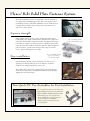

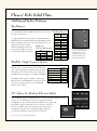
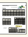


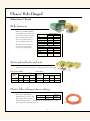

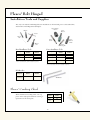
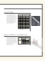
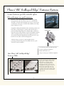
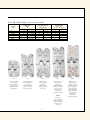


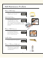

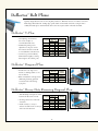
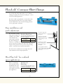


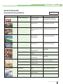


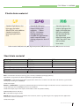
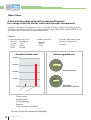

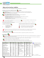


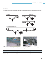
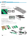
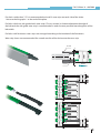


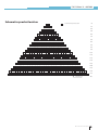

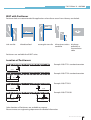
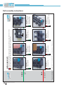

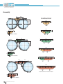


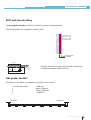
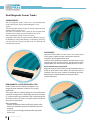

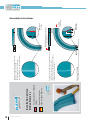

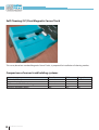


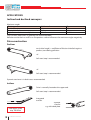
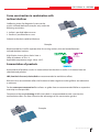


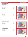

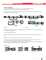

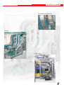

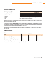

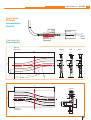

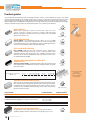
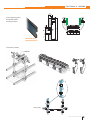
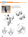


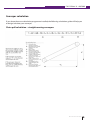
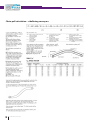

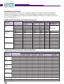


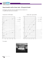


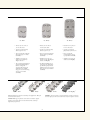

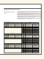

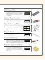
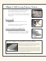
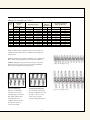
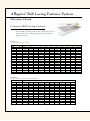


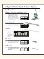


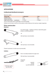

![AWD10SS [obsolete] User Manual](http://vs1.manualzilla.com/store/data/005777265_1-bc3e4afb4b891fb2fe3c32a930faa0e5-150x150.png)