1
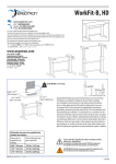
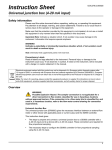
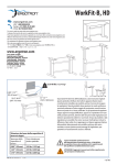
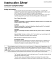
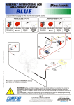
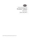
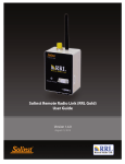
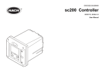
Catalog Number 2458
Data Logging Rain Gauge
USER MANUAL
February 2005 Edition 1
©Hach Company, 2005. All rights reserved. Printed in the U.S.A. ad/dp
Visit http://www.hach.com
Table of Contents
Section 1 Specifications......................................................................................................................................... 4
Section 2 General Information ............................................................................................................................... 5
2.1 Safety Precautions .............................................................................................................................................. 5
2.1.1 Use of Hazard Information......................................................................................................................... 5
2.1.2 Precautionary Labels................................................................................................................................. 5
2.2 Introduction ......................................................................................................................................................... 5
Section 3 Preparation of the Rain Logger ............................................................................................................ 9
3.1 Loading the InSight Software .............................................................................................................................. 9
3.2 Powering the Rain Logger................................................................................................................................... 9
3.3 Inserting the Rain Reader and Rain Logger in the Cradle .................................................................................. 9
3.4 Programming the Rain Logger .......................................................................................................................... 10
Section 4 Installation ............................................................................................................................................ 13
4.1 Location ............................................................................................................................................................ 13
4.2 Leveling the Rain Gauge................................................................................................................................... 13
4.3 Installing the Rain Logger ................................................................................................................................. 14
4.4 Remote Rain Logger System ............................................................................................................................ 14
Section 5 Operation .............................................................................................................................................. 17
5.1 Retrieving Data from the Rain Logger............................................................................................................... 17
Section 6 How to Order ........................................................................................................................................ 19
Section 7 Contact Information for Europe .......................................................................................................... 20
Section 8 Warranty................................................................................................................................................ 21
Appendix A Troubleshooting ............................................................................................................................... 23
A.1 Replacing the Battery ....................................................................................................................................... 23
A.2 Cleaning the Rain Gauge ................................................................................................................................. 23
A.3 RS232 Connection ........................................................................................................................................... 23
A.4 Problem Recording Data .................................................................................................................................. 23
Table of Contents
Page 3
Section 1
Specifications
Specifications are subject to change without notice.
Rain Gauge
Type
Tipping bucket with 8” diameter collector/funnel
Overall Dimensions
45.7 x 30.5 x 30.5 cm (18 x 12 x 12 in.)
Weight
4.2 kg (9.25 lb)
Resolution
0.01” rainfall per bucket tip
Accuracy
0.5% at 0.5” per hour
Base Mounting Plate
Spring loaded, 3-point adjustable
Materials of Construction
Epoxy coated aluminum and Anodized Aluminum (funnel screen is stainless steel)
Rain Logger
Enclosure
Impact resistant plastic
Type
Solid state memory, battery backed
Dimensions
2.54 x 7 x 10.5 cm (1 x 2.75 x 4.125 in.)
Weight
8.5 oz (0.24 kg)
Electronics
CMOS, protected to NEMA 4x, 6 requirements
Operating Temperature
0 to 57 °C (32° to 135 °F)
Storage Temperature
–29° to 66 °C (–20° to 150 °F)
Power Requirements
Replaceable 9 VDC alkaline battery
Battery Life
6 months, typical
Data Capacity
10,080 readings (i.e. 7 days at 1 minute recording intervals, 70 days at 10 minute
recording intervals)
Time Base Indicator
L.E.D. flashing once every 2.5 seconds indicates a good battery. 2–3 days of remaining battery
life when the L.E.D. stops flashing.
Data Interface
L.E.D. optically coupled RS232 interface
Rain Reader
Enclosure
Impact resistant plastic
Dimensions
2.54 x 7 x 10.5 cm (1 x 2.75 x 4.125 in.)
Weight
8.5 oz (0.24 kg)
Electronics
CMOS
Power Requirements
9 VDC, nominal; supplied via 115 VAC/9 VDC power adapter
Data Interface
L.E.D. optically coupled RS232 interface
Data Transfer Rate
4800 baud (fixed)
Computer Interface
RS232 serial cable, IBM PC compatible
InSight Software
Pentium PC with 133 MHz or higher processor
Windows 95, 98, 2000, NT 4.0, or XP operating systems
Minimum 64 Megabytes RAM
Hardware Requirements
Minimum 100 MB available hard drive space
9-pin serial port or 25-pin serial port with 9-pin adapter
VGA Graphics display with 800 x 600 or higher resolution, 256 colors
Mouse
Color printer for output of reports and graphs is recommended
Specifications
Page 4
Section 2
General Information
2.1 Safety Precautions
Please read this entire manual before unpacking, setting up, or operating this equipment. Pay
attention to all danger and caution statements. Failure to do so could result in serious injury to
the operator or damage to the equipment.
To ensure that the protection provided by this equipment is not impaired, do not use or install
this equipment in any manner other than that specified in this manual.
2.1.1 Use of Hazard Information
DANGER
Indicates a potentially or imminently hazardous situation which, if not avoided, could
result in death or serious injury.
CAUTION
Indicates a potentially hazardous situation that may result in minor or moderate injury.
Important Note: Information that requires special emphasis.
Note: Information that supplements points in the main text.
2.1.2 Precautionary Labels
Read all labels and tags attached to the instrument. Personal injury or damage to the
instrument could occur if not observed. .
This symbol, if noted on the instrument, references the instruction manual for operation
and/or safety information.
2.2 Introduction
This manual covers the Sigma Rain Logger and Remote Rain Logger systems. The Data
Logging Rain Gauge, Remote Rain Gauge, and InSight software measure and record data on
rainfall at a particular location. The Rain Logger systems consist of four main parts (see
Figure 1).
•
Rain Gauge—A device used to measure rainfall. Measurement is based on the principle
of an internal tipping bucket that is calibrated to collect 0.01 inches of rain. When this
amount is collected, the bucket tips and the process is restarted. The bucket tip is
recorded by the Rain Logger.
•
Rain Logger—A pocket-sized device which records the rainfall measured by the rain
gauge. It can hold 10,080 readings.
•
Rain Reader—A pocket-sized device which provides an interface between a PC and the
Rain Logger. This device connects to the serial port of the PC.
•
InSight Software—A program which allows storing, retrieving, and analyzing of data. It is
compatible with rain loggers, flow meters, and samplers. See the operating instructions
that came with the InSight software for a complete description of its functions.
General Information
Page 5
General Information
Figure 1
Data Logging Rain Gauge Components
1
2
4
5
6
TOP
TOP
TO TRANSFER DATA
TO TRANSFER DATA
ALIGN ARROWS
WITH READER
RAIN READER
ALIGN ARROWS
WITH READER
RAIN LOGGER
IN RAIN GAUGE:
INSTALL TOP UP
WITH BACK FACING
TIPPING BUCKET
3
7
1.
Rain Gauge
5.
Rain Logger
2.
Screen
6.
Cradle
3.
Funnel
7.
CD, Insight Software
4.
Rain Reader
Figure 2
Rain Logger System
TO
P
TA
DA
ER
SF
WS
RO
AR ER
IGN AD
AL H RE
WIT
AN
TO
TR
ER
GG
1
IN
RA
LO
IN
E:
UG
GA
IN
P UP NG
RA
L TO FACI
AL
ET
INST BACK BUCK
H G
WIT PPIN
TI
2
TO
P
ATA
RD
SFE
WS
RO
AR ER
GN AD
ALI H RE
WIT
3
AN
TO
TO
TR
IN
P
TO
ATA
RD
SFE
AN
WS
RO R
AR DE
GN EA
ALI ITH R
W
RA
TR
ER
ER
G
OG
L
IN
E:
UG
GA
P
IN
PU
RA
TO CING
LL
TA K FA ET
INS BAC BUCK
H G
WIT PPIN
TI
AD
IN
RA
RE
l
tria
us ne
Ind lkali
A
olt
9 V ery
tt
Ba
1.
Rain Gauge
2.
Rain Logger installed into cradle with Rain Reader
Introduction
Page 6
3.
PC with Insight software
General Information
Figure 3
Rain Gauge
254 mm
(10.00 inches)
6
1
2
305 mm
(12.00 inches)
3
254 mm
(10.00 inches)
4
5
(
216 mm
8.50 inches)
457 mm
(18.00 inches)
305 mm (12.00 inches)
1.
Sleeve, Rain Logger
4.
Leveling Wing nuts (4)
2.
Tipping Bucket
5.
Level
3.
Measured Rainfall, Drain (2)
6.
Mounting holes, ∅12.7 mm (∅ 0.5-inch) thru (4)
Introduction
Page 7
General Information
Figure 4
Rain Reader and Rain Logger
71.6 mm
(2.82 inches)
1
2
3
5
4
6
71.6 mm
(2.82 inches)
TOP
TO TRANSFER DATA
RAIN READER
106 mm (4.19 inches)
ALIGN ARROWS
WITH READER
106 mm (4.19 inches)
TOP
TO TRANSFER DATA
9
7
8
1.
Rain Reader
6.
Optical Communication Ports
2.
Rain Logger
7.
AC Power Connection
3.
LED, Power ON Indicator
8.
Serial Interface Cable
4.
Optical Communication Ports
9.
Battery Compartment Cover
5.
LED, Power ON Indicator
10. Screws (4)
Introduction
Page 8
ALIGN ARROWS
WITH READER
RAIN LOGGER
IN RAIN GAUGE:
INSTALL TOP UP
WITH BACK FACING
TIPPING BUCKET
10
Section 3
Preparation of the Rain Logger
3.1 Loading the InSight Software
1. Insert the CD into the CD-ROM drive. The CD should automatically run. If the CD does not
automatically run, follow the steps below:
a. Click START and select the Run function.
b. Click BROWSE in the Run dialog box.
c. Browse to the CD-ROM drive on your computer and double click setup.exe.
d. Click OK in the Run dialog box.
2. Follow the instructions as they appear on the screen.
3.2 Powering the Rain Logger
1. Remove the four screws from the face of the Rain Logger and remove the cover.
2. Attach a 9V battery to the battery clip, observing proper polarity.
3. Replace the cover and screw it into place. Be sure to replace the cover as shown in
Figure 5 so that the arrows on the cover label point towards the optical communication
port on the left side of the rain logger case.
Note: Improper placement of the cover can result in no data being recorded when the Rain Logger is
installed in the Rain Gauge.
Figure 5
Battery Installation
1
TO
P
TO
T
RA
NS
FE
RD
AL
AT
A
WI IGN
TH AR
RE RO
AD WS
ER
RA
IN
IN
Screws
LO
GG
IN
I
GA
WI NSTA
U
T
TIP H BA LL TO GE:
PIN CK P U
G B FA P
UC CIN
KE G
T
3
1.
RA
2.
Cover, Rain Logger
3.
ER
2
9V Battery
3.3 Inserting the Rain Reader and Rain Logger in the Cradle
Insert the Rain Reader and Rain Logger into the cradle. Be sure the Reader is inserted before
the Logger and that the labels face out (see Figure 6).
1. Insert the Rain Reader into the left side of the cradle.
Preparation of the Rain Logger
Page 9
Preparation of the Rain Logger
2. Insert the Rain Logger into the right side of the cradle. Align the arrows on the labels of
the Rain Reader and Rain Logger to point at each other.
3. Connect power to the Rain Reader using either the AC power adapter included, or a 9V
battery installed on the cradle.
Figure 6
Rain Reader and Rain Logger in the Cradle
1
2
TOP
TOP
TO TRANSFER DATA
TO TRANSFER DATA
3
ALIGN ARROWS
WITH READER
ALIGN ARROWS
WITH READER
RAIN LOGGER
RAIN READER
4
IN RAIN GAUGE:
INSTALL TOP UP
WITH BACK FACING
TIPPING BUCKET
6
5
1.
Cradle
4.
Battery, 9V
2.
Rain Reader
5.
Power supply to Rain Reader (battery power or AC power)
3.
Rain Logger
6.
9-pin serial interface connector (Rain Reader to PC)
3.4 Programming the Rain Logger
1. Connect the Rain Reader serial interface cable to the 9-pin serial port (or a 25-pin serial
port with a 9-pin adapter) on your PC. If the computer has more than one serial port,
make note of which one is going to be used for the Rain Reader.
2. Start up the InSight software. Select the Rain Logger from the list of instruments.
3. Select the COM port connected to the Logger. The Rain Reader baud rate is fixed
at 4800.
Programming the Rain Logger
Page 10
Preparation of the Rain Logger
4. Click OK. A Connected to Sigma Rainlogger dialog box should appear. This indicates the
Rain Reader and PC are properly connected and communicating (see Figure 7). If it does
not appear, see Appendix A on page 23.
Figure 7
Connected to Sigma Rainlogger
5. Once connected, click REMOTE PROGRAMMING..
6. Enter the information for the site where the Rain Gauge will be installed.
•
Site Id Enter a description for the location of the Rain Gauge.
•
Start Condition Use the drop-down menu to select between Record Immediately or
Record on First Tip.
•
Interval Use the drop-down menu to enter the interval at which the Rain Logger will
record the data.
•
Memory Mode Use Slate Mode to have the recordings stop after the memory is full.
Use Wrap Mode to have the oldest data replaced with new data when the memory is
full.
7. Click the clock option to program the clock. Click either Use PC Time/Date or Use
User-Entered Time/Date. If selecting Use User-Entered Time/Date, the needed
information must be manually entered in the Enter New Logger Time/Date fields. Click
PROGRAM.
8. After the clock has been programmed, InSight returns to the Connected to Sigma
Rainlogger dialog box. If the information is correct, click OK to return to the main menu.
9. Click the Clear Logger Memory option to clear logger data points. The site and clock
information will not be erased.
10. Click RETURN and the logger is now programmed.
Programming the Rain Logger
Page 11
Visit us at www.hach.com
Section 4
Installation
DANGER
Only qualified personnel should conduct the installation tasks described in this section
of the manual.
4.1 Location
1. Install the rain gauge in a clear area away from buildings and trees which could block the
natural fall of the rain. Pick a location which is as level as possible and will assure a
representative sample of rainfall for the area.
2. The base plate can be mounted to any flat surface using the four mounting holes located
in the corners of the plate. Attach the mounting plate to the ground with small stakes or
bolts depending on the mounting surface.
Note: If the Remote Rain Logger System is being installed, route the cable from the Rain Gauge to the
place where the Remote Rain Logger housing will be located. The Remote Rain Logger housing may be
located 25 ft away from the Rain Gauge with the standard cable, or up to 125 ft away using the optional
100 ft extension cable.
4.2 Leveling the Rain Gauge
For accurate rainfall measurements, the rain gauge must be levelled using the internal bullseye level located inside the gauge.
1. Remove the screen and rain gauge funnel. Be sure that no packing material is inside or
under the gauge and that the tipping bucket can move freely about the pivot point.
2. Using the three wing nuts located on the base, adjust the gauge so that the air bubble is
centered in the circle of the bulls-eye level.
If the Remote Rain Logger System is being installed, replace the screen and the rain gauge
funnel and go to Section 4.4 on page 14.
Figure 8
Inside the Rain Gauge
1
4
2
5
3
6
1.
Sleeve, Rain Logger
4.
Rain Logger (installed)
2.
Sensor, Tipping Bucket
5.
Power ON Indicator
3.
Tipping Bucket
6.
Level
Installation
Page 13
Installation
4.3 Installing the Rain Logger
1. Slide the Rain Logger into the mounting sleeve in the Rain Gauge with the side marked
TOP up (see Figure 8).
Note: Use care not to tip the bucket during Rain Logger installation since false rainfall will be recorded.
Incorrect placement of the Rain Logger in the Rain Gauge will result in no recorded data.
2. Replace the screen and the rain gauge funnel.
4.4 Remote Rain Logger System
1. Remove the top cover of the Remote Rain Logger housing by rotating it counter-clockwise
to unscrew it from the housing (see Figure 10).
2. Install the Rain Logger in the metal bracket by sliding the top of the Rain Logger into the
leaf springs and snapping the bottom of the Rain Logger under the lip of the metal
bracket. Make sure that the arrows on the Rain Logger label face the same direction as
the arrows on the bracket label.
3. Install two 9V batteries in the holders located on the metal bracket, observing proper
polarity.
4. Replace the top cover of the Remote Rain Logger housing.
5. Attach the cable from the Rain Gauge to the connector on the top of the Remote Rain
Logger housing.
Figure 9
Remote Rain Logger Overview
1
2
3
TOP
TO TRANSFER DATA
INSTALL LOGGER
WITH ARROWS LINED UP
FACING SAME DIRECTION
114.3 mm
( 4.50 inches)
197 mm (7.75 inches)
1.
Housing, Remote Rain Logger Body
2.
Top Cover, Remote Rain Logger
3.
Connector
Installing the Rain Logger
Page 14
Installation
Figure 10
Remote Rain Logger
3
2
TOP
TO TR
ANSF
ER DA
TA
ALIGN
WITH ARROWS
READ
ER
RAIN
LOGG
IN RA
IN GA
UGE:
INSTAL
L TOP
WITH
UP
BA
TIPPIN CK FACING
G BU
CKET
ER
TOP
DATA
NSFER
TO TRA
4
ER
L LOGG
UP
INSTAL WS LINED ION
CT
ARRO
WITH SAME DIRE
FACING
1
5
6
1.
Housing, Remote Rain Logger Body
4.
9V Battery (2)
2.
Top Cover, Remote Rain Logger
5.
Wing nut
3.
Rain Logger
6.
Bracket
Remote Rain Logger System
Page 15
Visit us at www.hach.com
Section 5
Operation
5.1 Retrieving Data from the Rain Logger
1. Remove the screen and funnel from the Rain Gauge.
2. Carefully remove the Rain Logger from the bracket.
3. It is recommended to clean the Rain Gauge and tipping bucket while the Rain Logger is
removed so false data won’t be recorded.
4. Insert the Rain Reader and Rain Logger in the cradle as it was done during programming
(see Section 3.3 on page 9).
5. Be sure the Rain Reader serial interface cable is connected to the 9-pin serial port (or a
25-pin serial port with a 9-pin adapter) on your PC. If the computer has more than one
serial port, make note of which one is going to be used for the Rain Reader.
6. Start up the InSight software.
7. Select the Rain Logger from the list of instruments.
8. A Connected to Sigma Rainlogger dialog box should appear. This indicates the Rain
Reader and PC are properly connected and communicating (see Figure 7 on page 11). If
it does not appear, see Appendix A on page 23.
9. Once connected, click RETRIEVE LOGGED DATA. This will retrieve and store all data from
the logger onto the PC. See the InSight manual for information on Data Analysis. Be sure
all data is store successfully before continuing.
10. If all data was stored, click CLEAR LOGGER MEMORY. This will erase all rainfall data from
the Rain Logger.
Figure 11
Clear Logger Memory
11. Click OK to confirm.
12. If needed, make changes to the programmed information (Interval, Start Condition, or
Memory Mode) by clicking REMOTE PROGRAMMING.
13. Click RETURN and the logger can now be returned to the Rain Gauge.
Operation
Page 17
Operation
14. Slide the Rain Logger into the mounting sleeve in the Rain Gauge with the side marked
Top up (Figure 8 on page 13).
Note: Use care not to tip the bucket during Rain Logger installation since false rainfall will be recorded.
Incorrect placement of the Rain Logger in the Rain Gauge will result in no recorded data.
15. Replace the screen and the rain gauge funnel.
Retrieving Data from the Rain Logger
Page 18
Section 6
How to Order
Ordering Information for the U.S.A.
By Telephone:
(800) 635-4567
By Fax:
(970) 461-3915
By Mail:
Hach Company
P.O. Box 389
Loveland, Colorado 80539-0389
U.S.A
Ordering information by E-mail:
[email protected]
Information Required
•
Hach account number (if available)
•
Billing address
•
Your name and phone number
•
Shipping address
•
Purchase order number
•
Catalog number
•
Brief description or model number
•
Quantity
Ordering Information for Outside the U.S.A. and Europe
Hach maintains a worldwide network of dealers and distributors. To locate the representative
nearest you, send e-mail to [email protected] or visit www.hach.com.
Technical Support
Technical and Customer Service Department personnel are eager to answer questions about
our products and their use. In the U.S.A., call 1-800-635-1230. Outside the U.S.A. and Europe,
send e-mail to [email protected].
Repair Service
Authorization must be obtained from Hach before sending any items for repair. Please contact
the Hach Service Center serving your location.
Hach Company
P.O. Box 389
Loveland, Colorado, 80539-0389 U.S.A.
Telephone: 1-800-635-1230 or (970) 669-3050
Fax: (970) 669-2932
How to Order
Page 19
Section 7
Contact Information for Europe
For technical support, repair service, and ordering information please refer to the contact
information below for your specific country. For additional information, visit www.hachlange.com.
Austria
Dr. Bruno Lange Ges. MBH
Industriestraße 12
A - 3200 Obergrafendorf
Tel. +43 (0)27 47 74 12
Fax +43 (0)27 47 42 18
[email protected]
Italy
Dr. Bruno Lange s.r.I.
Via Riccione, 14
I-20156 Milano
Tel. +39 02 39 23 14-1
Fax +33 02 39 23 14-39
[email protected]
Belgium
Dr. Lange
Motstraat 54
B-2800 Mechelen
Tel. +32 (0)15 42 35 00
Fax +32 (0)15 41 61 20
[email protected]
Poland
Hach Lange sp.zo.o.
ul. Opolska 143 a
PL-52-013 Wroclaw
Tel. +48 71 3 42 10 -81
Fax +48 71 3 42 10-79
[email protected]
Denmark
Dr. Lange Danmark A/S
Jernhoolmen 34-40
DK-2650 Hvidovre
Tel. +45 (0)36 77 29 11
Fax +45 (0)36 77 49 11
[email protected]
The Netherlands
Dr. Lange Nederland B.V.
Laan an Westroijen 2a
NL-4003 AZ Tiel
Tel. +31 (0) 3 44 63 11 30
Fax +31 (0) 3 44 63 11 50
[email protected]
France
Hach Lange
Hach SAS
33 Rue du Ballon
F-93165 Noisy Le Grand
Tel. +33 (0)1 48 15 80 80
Fax +33 (0)1 48 15 80 00
[email protected]
Spain/Portugal
Hach Lange S.L.U.
c/ Araba, 45. Apdo. 220
E-20800 Zarauz/Guipùzcoa
Tel. +34 9 43 89 43 79
Fax +34 9 43 13 02 41
[email protected]
Germany
Dr. Bruno Lange GmbH
& CO. KG
Willstätterstr. 11
D-40549 Düsseldorf
Tel. +49 (0)2 11 52 88-0
Fax +49 (0)2 11 52 88-143
[email protected]
Sweden
Hach Lange AB
Vinthundsvägen 159A
S-128 62 Sködal
Tel. +46 (0)8 7 98 05 00
Fax +46 (0)8 7 98 05 03
[email protected]
Great Britain
Hach Lange LTD
Lennox Road
Basingstoke
Hampshire, RG22 4AP
Tel. +44 (0)12 56 33 34 03
Fax +44 (0)12 56 33 07 24
[email protected]
Switzerland
Dr. Bruno Lange AG
Juchstrasse 1
CH-8604 Hegnau
Tel. +41(0)1 9 45 66 10
Fax +41(0)1 9 45 66 76
[email protected]
Contact Information for Europe
Page 20
Section 8
Warranty
Hach Company warrants this product to the original purchaser against any defects that are due to faulty
material or workmanship for a period of one year from date of shipment.
In the event that a defect is discovered during the warranty period, Hach Company agrees that, at its
option, it will repair or replace the defective product or refund the purchase price, excluding original
shipping and handling charges. Any product repaired or replaced under this warranty will be warranted
only for the remainder of the original product warranty period.
This warranty does not apply to consumable products such as chemical reagents; or consumable
components of a product, such as, but not limited to, lamps and tubing.
Contact Hach Company or your distributor to initiate warranty support. Products may not be returned
without authorization from Hach Company.
Limitations
This warranty does not cover:
•
Damage caused by acts of God, natural disaster, labor unrest, acts of war (declared or undeclared),
terrorism, civil strife or acts of any governmental jurisdiction
•
Damage caused by misuse, neglect, accident or improper application or installation
•
Damage caused by any repair or attempted repair not authorized by Hach Company
•
Any product not used in accordance with the instructions furnished by Hach Company
•
Freight charges to return merchandise to Hach Company
•
Freight charges on expedited or express shipment of warranted parts or product
•
Travel fees associated with on-site warranty repair
This warranty contains the sole express warranty made by Hach Company in connection with its
products. All implied warranties, including without limitation, the warranties of merchantability and fitness
for a particular purpose, are expressly disclaimed.
Some states within the United States do not allow the disclaimer of implied warranties and if this is true
in your state the above limitation may not apply to you. This warranty gives you specific rights, and you
may also have other rights that vary from state to state.
This warranty constitutes the final, complete, and exclusive statement of warranty terms and no person
is authorized to make any other warranties or representations on behalf of Hach Company.
Limitation of Remedies
The remedies of repair, replacement or refund of purchase price as stated above are the exclusive
remedies for the breach of this warranty. On the basis of strict liability or under any other legal theory, in
no event shall Hach Company be liable for any incidental or consequential damages of any kind for
breach of warranty or negligence.
Warranty
Page 21
Visit us at www.hach.com
Appendix A Troubleshooting
A.1 Replacing the Battery
The 9V batteries in the Rain Logger and Remote Rain Logger typically last for 6 months. An
L.E.D. flashing once every 2.5 seconds indicates a good battery. When the L.E.D. stops
flashing, two to three days of battery life remain but it is recommended to replace the battery
immediately at that time.
A.2 Cleaning the Rain Gauge
Every time the Rain Logger is removed to record the data, clean the Rain Gauge with a soft,
wet cloth. Pay particularly close attention to the following areas:
•
Be sure the tipping bucket can still tip on its axis. Debris can cause inaccurate
readings.
•
Be sure the funnel is not clogged and thoroughly clean the screen. Debris covering
the screen or in the funnel can cause inaccurate readings.
•
Check all connections including the Rain Logger bracket for signs of damage or
interference that may cause inaccurate readings.
A.3 RS232 Connection
Use Table 1 to determine what the problem was when attempting to connect the Rain Reader
with your PC. If all else fails, contact Technical Support.
Table 1 RS232 Connection Errors
Possible Problems
Solutions
The RS232 cable and receptacle are not in good condition or
tightly connected.
Replace cable or tighten connection.
The com port is not enabled on your PC.
Examine your hardware profile and check your computer
manual. Common settings are:
COM 1 IRQ 4 Address O3F8
COM 2 IRQ 3 Address O2F8
COM 3 IRQ 4 Address O3E8
COM 4 IRQ 3 Address O3E8
The unit does not have adequate power supply. (Check Status
screen)
Check the fuses and evaluate the power supply.
The 9-pin and 25-pin connections are not working properly.
Try a different computer and check the cable with an
Ohm meter.
A.4 Problem Recording Data
If the Rain Logger is not recording any data from the tipping bucket:
•
Check that the screen is free of debris and that water can run through the funnel to the
tipping bucket.
•
Check that the tipping bucket can tip, debris or shipping material might block the
tipping bucket from recording data.
•
Check that the Rain Logger is properly installed. Center the Rain Logger in the bracket
in the Rain Gauge. There is enough movement where the Rain Logger doesn’t pick up
rain data occasionally.
•
After replacing batteries, check the cover of the Rain Logger. If the cover is turned
around, the Rain Logger is improperly installed.
After replacing batteries, check that the red power LED is flashing. This is a visual indication
that the unit is running properly.
Troubleshooting
Page 23
Visit us at www.hach.com