1
Basic Gear Design and Manufacturing—Plastic Gears
60-104w
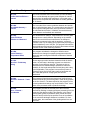
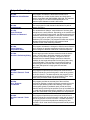
Gear Mesh Geometry External
This is a model of the contact conditions between two external
spur or helical involute gears. The contact ratios, start of active
profile, specific sliding and many other geometrical conditions
are calculated and checked. In addition, the tooth thickness,
center distance and backlash are calculated.
60-108w
Gear Mesh Geometry –
Internal
This is a model of the contact conditions between two internal
spur or helical involute gears. The contact ratios, start of active
profile, specific sliding and many other geometrical conditions
are calculated and checked. In addition, the tooth thickness,
center distance and backlash are calculated.
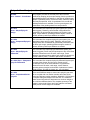
60-145w
Tooth Thickness
Effective vs. Measured
The measured and “effective” tooth thickness of involute gears
and splines are usually different. Depending on the method
used for the tooth thickness measurement, the difference
between the measured value and the apparent, or effective,
thickness “seen” by the mating gear or spline may be enough to
prevent satisfactory use of the part. This program will make the
required adjustments between the effective and measured tooth
thickness for the usual measuring methods.
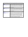
60-146w
Center Distance Temperature Effect
This program calculates the changes in effective center
distance due to changes in operating temperature when the
gears and gear housing have different coefficients of thermal
expansion.
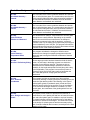
60-180w
Gear Set - Preliminary Sizing
Once a target gear ratio has been determined and the load is
known, the next step in the design process is to obtain the
geometry for a preliminary gear set. This gear set is then
checked with more detailed design equations to determine
suitability for the loads and speeds involved (along with a duty
cycle if applicable). This program is structured to produce a
preliminary gear set from the data usually at hand when the
ratio, load, and speed of a single gear set has been
determined.
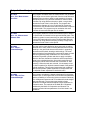
60-410w
Gear - External –
Coordinates
This program provides an accurate plot of the tooth form
produced by hobbing or shaping (and post processing) from the
production gear drawing and the tool drawing. In the case of
molded gears (plastic or powdered metal) circular arc fillets,
chamfers and tip relief may be specified. A set of coordinates
for the mold with shrinkage allowance is available. For form
ground gears, the coordinates of the grinding wheel form are
produced.
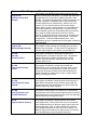
60-610w
Gear - Design and Analysis –
Plastic
The purpose of this model is to provide an accurate set of
coordinates for use in plotting the final form of external involute
spur and helical plastic gears. In addition to a plot of the teeth,
the model furnishes numerical results for many of the design
parameters of interest to the designer. The model can be used
for the design of a plastic gear set and the necessary tooling
and, if load and material data is entered, an analysis of the load
capacity will be made.