1
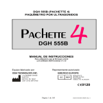
DGH 555 (PACHETTE 3) ULTRASONIC PACHYMETER PACHETTE DGH 555 OPERATOR’S MANUAL Equipment Manufactured By Authorized Representative DGH TECHNOLOGY, INC. EMERGO EUROPE 110 SUMMIT DR IVE SUITE B EXTO N, PA 1934 1 USA (6 10) 594 -9100 EC REP Molenstraat 15 2513 BH, The Hague The Netherlands Phone: +31.70.345.8570 0120 555-INS-OMENG Rev: 2 i TABLE OF CONTENTS I. INTRODUCTION .................................................................................................................................. 1 II. FEATURES ............................................................................................................................................ 2 III. GENERAL DESCRIPTION................................................................................................................... 3 IV. POWER-UP SEQUENCE ...................................................................................................................... 9 V. CONFIGURING THE PACHETTE 3 ................................................................................................. 11 V.A. V.B. VI. Continuous Average Mode (Factory Default Mode) .................................................................... 11 Mapping Mode ........................................................................................................................... 14 OBTAINING PACHYMETRY MEASUREMENTS .......................................................................... 19 VI.A. Obtaining Measurements With Continuous Average Mode ......................................................... 19 VI.B. Obtaining Measurements With The Mapping Mode ................................................................... 21 VII. PROBE QUALITY............................................................................................................................... 23 VIII. VERIFYING PACHETTE 3 CALIBRATION .................................................................................... 24 IX. CARE AND MAINTENANCE............................................................................................................. 25 IX.A. IX.B. IX.C. IX.D. IX.E. IX.F. IX.G. X. Cleaning and Disinfecting Instructions....................................................................................... 25 Transport and Storage Conditions .............................................................................................. 25 Operating Conditions ................................................................................................................. 25 Warranty.................................................................................................................................... 26 Lifetime / Shelf-life .................................................................................................................... 26 Instructions for Changing Batteries ............................................................................................ 26 Service ....................................................................................................................................... 27 INDICATIONS FOR USE, PRESCRIPTION DEVICE STATEMENT, PRECAUTIONS, INTENSITIES AND CAPABILITIES ................................................................................................. 29 X.A. X.B. X.C. X.D. X.E. X.F. X.G. X.H. Indications For Use .................................................................................................................... 29 Prescription Device .................................................................................................................... 29 Tissue Exposure To Ultrasound Energy ...................................................................................... 29 Ultrasonic Intensities.................................................................................................................. 29 Biometric Measurement Capabilities .......................................................................................... 30 Classification ............................................................................................................................. 31 Precautions................................................................................................................................. 31 EMI / EMC Compliance............................................................................................................. 31 ii LIST OF FIGURES Figure III-A Figure III-B Figure III-C Figure III-D Figure III-E DGH 555 Pachette 3 Front View. ...................................................................................................... 3 DGH 555 Pachette 3 Back View. ....................................................................................................... 5 DGH 555 Pachette 3 Side View ......................................................................................................... 6 DGH 555 Pachette 3 Back Panel........................................................................................................ 7 DGH 555 Pachette 3 Electronic CalBox ............................................................................................. 8 1 I. INTRODUCTION Ultrasonic Pachymetry is an integral part of refractive corneal surgery as well as certain screening procedures that are a function of corneal thickness. The DGH 555 Ultrasonic Pachymeter (Pachette 3) is an ultrasonic pachymeter that uses echo spike techniques to measure the thickness of the cornea. This is the recommended method for obtaining corneal thickness measurements because it offers the following advantages: • • • • • Reproducibility High accuracy Ability to take measurements anywhere on the cornea Measurements are not dependent upon patient fixation Ease of use The corneal thickness measurement may then be used in many different ways including: Lasik, glaucoma screening and corneal edema check for extended wear contact lens patients. The Pachette 3 was designed to provide a means of obtaining fast, accurate, corneal thickness measurements with a battery operated instrument that is simple to use, economical, and ultra-portable. We invite you to read this manual carefully to discover how quickly and easily the Pachette 3 can be integrated into your practice. 2 II. FEATURES The Pachette 3 is manufactured with high quality components that are designed and built using the latest technological concepts. The result is an advanced and powerful pachymeter that offers practicality and reliability. The following features are just a sample of the characteristics and capabilities of the Pachette 3. Standard Features • • • • • • • • • • • • • • • Simple to use. Turn on power and the Pachette 3 is ready to take measurements. Automatic measurement mode for operation without an activation switch. Rapidly obtains and stores up to 25 measurements at a single location. Displays the current measurement, the average, and the standard deviation of all measurements taken. Mapping mode for obtaining and storing up to 33 actual and biased corneal mapped measurements. 16 x 2 LCD character display with LED backlighting allows easy visibility. Proven measurement algorithm which yields accurate, reproducible measurements in a fraction of a second. Ultra-Portable. Battery operated, lightweight and can be easily transported from office to hospital in its custom carrying case. Operator feedback. Audible signal indicates when a valid measurement is complete. Personalized configuration. User-friendly keypad allows selection of number of measurements to be obtained, and selection of delay time between measurements. Configuration memory. Once personally configured for the operator, non-volatile memory provides permanent storage of configuration data, even when the Pachette 3 is turned off and the batteries are removed. Built in IOP Correction Calculation capabilities to assist in glaucoma screening. Unit comes in a protective holster with a built in tilt stand for easy viewing. When not in use the probe cord can be wrapped up and probe can be stored in the custom molded holster cavity for protection while being transported or stored. Probe is detachable and can be easily removed by the operator for cleaning or, if necessary, for replacement. 3 III. GENERAL DESCRIPTION Front View Figure III-A DGH 555 Pachette 3 Front View. 1 LCD Display 16 x 2 character display used to present measurement data and/or configuration parameters to the operator. 2 Probe Clips Two clips molded into the protective case to place probe between cases. 3 PWR Key Pressing this key turns the Pachette 3 on. When the Pachette 3 is on, pressing and holding this key turns the Pachette 3 off. Also used in conjunction with the DEL key to enter the CalBox mode. 4 4 DEL Key Used to erase a single measurement from a group of measurements. Also used in conjunction with the PWR key to enter the CalBox mode. 5 CLR Key This key is used to erase all obtained measurements whenever it is desired to begin a new measurement sequence. 6 ENT Key In measurement mode, pressing key will display battery status. In configuration mode, the key is used to advance to the next configurable parameter. The key is also used to display the IOP correction calculation when the key is pressed and held (Continuous Avg mode only). 7 CFG Key Used to enter and exit the configuration mode. Also used to display the unit model number, serial number, software version and option number when the key is pressed and held. 8 OS Key Press key to review or take measurements of the LEFT eye. NOTE: Key is used only when the unit is configured for the bilateral mode. / 9 Keys Used to review measurements or to program options and numerical values presented on the display. 10 OD Key Press key to review or take measurements of the RIGHT eye. NOTE: Key is used only when the unit is configured for the bilateral mode. 5 Back View Figure III-B DGH 555 Pachette 3 Back View. 1 Probe Holder Used to hold or store probe when not in use or during transport. 2 Probe Connector Holder Used to hold or store probe connector when not in use or during transport. 3 Tilt Stand Used to place unit in tilted position on a flat surface. 6 Side View Figure III-C DGH 555 Pachette 3 Side View 1 Probe Cord Wrap Place to wrap the probe cord when not in use or during transport. 2 Probe Connector The connector that mates to the connector on the probe cable. 3 Tilt Stand Used to place unit in tilted position on a flat surface. 7 Back Of Unit Figure III-D DGH 555 Pachette 3 Back Panel 1 Back Panel Label This label contains the model number and serial number for the unit. It also provides contact information for DGH Technology, Inc and the following classification and attention symbols: This symbol indicates the degree of protection against electric shock. The Pachette 3 is classified as type BF equipment. ! 0120 This symbol cautions the operator to read the operating manual. This mark indicates that Notified Body 0120 (SGS United Kingdom Ltd) has certified the management system of DGH Technology, Inc. meets the requirements of Directive 93/42/EEC Annex II (excluding section 4) for ultrasonic pachymeters. This symbol located on the DGH 555 indicates that the equipment consists of 8 electronic assemblies and other components that may be subject to Directives 2002/96/EC, 2003/108/EC, and 2002/95/EC of the European parliament, which advises that electrical and electronic devices must not be disposed of as normal domestic refuse. In order to prevent environmental risks or endangerments by non-professional disposal, the disposal of this product, including any accessories, must comply with valid practices as outlined in Directives 2002/96/EC, 2003/108/EC, and 2002/95/EC and local regulations. All electronic components and systems should be returned to Orignal Manufacturer for disposal. 2 Battery Door This door provides access to the battery compartment. Calibration Standard To check Pachette 3 calibration, an electronic Calibration Verification Box “CalBox” (below) is used to simulate the thickness of the cornea. Instructions for using the CalBox are given in section VIII and they are also printed on the CalBox label. It is recommended that calibration verification be performed at least once a day. TECHNOLOGY, INC. 1. With the Pachette 3 turned off, disconnect the probe and then connect the CalBox cable to the Pachette 3. 2. Enter CalBox mode by holding in the DEL key and turning on the Pachette 3. 3. Press the CalBox POWER key until the LED lights up. 4. Observe that all Pachette 3 measurements are within ±5um. (See user’s manual for further details) 5. Exit CalBox mode by pressing the CLR key. 3 PACHETTE CalBox POWER Model DGH 555 Figure III-E DGH 555 Pachette 3 Electronic CalBox 9 IV. POWER-UP SEQUENCE NOTE: The Pachette 3 is shipped with (2) AA batteries installed and the probe cord wrapped around the cord wrap on the protective holster, with the probe seated in the protective cavity. (When necessary, refer to section IX.E for Instructions for Changing Batteries). 1. Remove the probe from the cavity by grasping the body of the probe at the access opening in the holster. Do not pull on the probe cord to remove the probe as this can cause damage to the probe. It is recommended that the probe be returned to the cavity for protection when transporting the Pachette 3, or when the unit is not being used. 2. Unwrap the probe cord. The probe connector may be removed from the holster cavity by gently pulling on the probe cord at the connector strain relief. 3. Carefully align probe connector for proper mating orientation and insert into the opening on the right side of the holster. Reference Figure IV-C for connector orientation. 4. Gently press probe into opening until probe is properly mated. Inspect the probe tip to verify it is clean and free of any nicks, scratches or any other defect that could injure the cornea. (Refer to section IX.A. for Cleaning and Disinfecting Instructions) 5. Flip tilt stand away from holster and place unit on flat surface in tilted position. 6. Turn on the unit. 7. The Pachette 3 performs an internal self-test function. 8. Unit will briefly display battery status as indicated: BATTERY OK E 9. F When the power-up sequence is finished, the display will indicate: OD Avg 0 = 0µ µ Std Dv = 0.0µ µ The Pachette 3 is now ready to take corneal measurements. If any default parameters need to be modified, refer to section V. Otherwise, refer to section VI for a detailed de- 10 scription of the proper method for obtaining measurements. During use, the Pachette 3 is designed to conserve battery life. Therefore the unit has three modes: Measurement Mode – Unit will take a measurement when applanated to the cornea. In this mode display will indicate: OD Avg 0 = 0µ µ Std Dv = 0.0µ µ Standby Mode – The unit will go into this mode if a measurement is not attempted within one minute from power up or a previous measurement. The one minute factory default delay can be adjusted from 0.5 to 9.5 minutes by accessing the configuration menu as described in section VI. The display will stay active, but a measurement cannot be obtained. In this mode you can still access the configuration menu and review all measurements. When the unit enters this mode you will hear a beep and the display will have a flashing cursor in the bottom left corner as indicated: OD Avg 0 = 0µ µ Std Dv = 0.0µ µ To return to measurement mode, press the PWR key. Sleep Mode – If any key is not pressed for three minutes after the unit went into standby mode, the unit will power down into Sleep Mode. In this mode the display will go blank and the unit will appear to be off, but all the measurements that were taken can still be retrieved. Press the PWR key and the unit will perform an internal test, display battery status, and then the display will indicate: Clear All Meas? ↑=Yes ↓ =No Press the Press the key to clear all measurements. key to retrieve all measurements. 11 V. CONFIGURING THE PACHETTE 3 Configuration Overview When shipped from the factory, the Pachette 3 is ready to take corneal measurements. It is not necessary to setup or configure anything. However, the Pachette 3 has been designed to allow the operator to modify certain default parameters to tailor the instrument to meet one’s needs. Once modified, these parameters are permanently stored in nonvolatile memory and are automatically recalled each time the unit is powered up. To change a parameter, the operator must access the configuration menu. The following procedure explains how to access the configuration menu and modify the default parameters. The Pachette 3 was designed to obtain multiple corneal measurements at a single location and generate an average for those measurements. In addition, the mapping mode permits the operator to take a single measurement at different positions on the cornea. With this mode enabled, the Pachette 3 can be programmed to record measurements at a maximum of 33 different positions. However, the operator must keep track of which measurement belongs to each corneal position. This can be achieved with the help of corneal thickness charts, which are available upon request from DGH Technology, Inc. Changing Parameters On The Configuration Menu A complete list of all the possible parameters on the configuration menu is given in Table 1. The procedures below show how to activate the configuration menu and modify the parameters on the Pachette 3. V.A. Continuous Average Mode (Factory Default Mode) 1. Press the CFG key and the display will indicate: OPERATIONAL MODE Continuous avg 2. or keys to Press ENT key to continue in Continuous Avg mode or press the change the operational mode from Continuous Avg to Mapping. Refer to section V.B to continue in Mapping Mode. In Continuous Avg mode display will indicate: 12 STD. DEVIATION Enabled 3. Use the or keys to enable or disable standard deviation. Press the ENT key to confirm your selection and the display will then indicate: BILATERAL MODE Enabled 4. or keys to enable or disable bilateral mode. Press the ENT key to conUse the firm your selection and the display will then indicate: AUTO SWITCH OD/OS Enabled 5. Use the or keys to enable or disable auto switch mode. Press the ENT key to confirm your selection and the display will then indicate: OD/OS SWITCH DLY 4.0 sec 6. Use the or keys to select the time (in seconds) that the unit will wait, after completing measurements on one eye, before switching to the other eye. Press the ENT key to confirm your selection and the display will then indicate: NUMB OF MEAS 25 7. Use the or keys to select the total number of measurements, from 1 to 25, that you wish to obtain. Press and release either key to change the current value slowly, one number at a time, or press and hold the key to scroll through the values more quickly. Press the ENT key to confirm your selection and the display will then indicate: AUTO REP DELAY <50 msec 13 8. Use the or keys to select the desired value for the auto repeat delay. This is the period of time that the unit will wait between consecutive measurements while the probe is properly applanated to the cornea. Press the ENT key to confirm your selection and the display will then indicate: DELAY TO STANDBY 1.0 min 9. Use the or keys to select the desired value for the standby delay. This is the period of time that the unit will wait before entering standby mode if no measurements are attempted. Press the ENT key to confirm your selection and the display will then indicate: BATTERY TYPE Rechargeable 10. Use the or keys to select battery type, Alkaline or Rechargeable. Press the ENT key to confirm your selection and the display will then indicate: BACK LIGHT OFF in Standby 11. Use the or keys to select the type of back light desired. The choices are back light always on, always off, or normally on and then shutting off in Standby mode. Press the ENT key to confirm your selection and the display will then indicate: BRIGHTNESS 12. Use the or keys to select the desired display brightness. Press the ENT key to confirm your selection and the display will then indicate: CONTRAST 13. Use the or keys to select the desired display contrast. Press the ENT key to confirm your selection and the display will then indicate: 14 VOLUME 14. Use the or keys to select the desired alarm volume. 15. Press the ENT key to return to the beginning of the configuration mode or press the CFG key to exit the configuration mode. If you did not make any changes the display will read “Config Not Changed” and return to measurement mode. If you changed any parameter the display will indicate: Save New Config? ↑=Yes ↓ =No Press press to save changes and return to measurement mode using new parameters, or to restore previous configuration and return to measurement mode. Note: You can press the CFG key at any time to exit the configuration mode. 16. Pachymetry measurements may now be taken. Refer to section VI for a detailed description of the proper method for obtaining measurements. V.B. Mapping Mode 1. Press the CFG key and the display will indicate: OPERATIONAL MODE Continuous Avg 2. Use the or keys to change the operational mode from Continuous Avg to Mapping. Press the ENT key to confirm your selection and the display will then indicate: BILATERAL MODE Enabled 3. Use the or keys to enable or disable bilateral mode. Press the ENT key to confirm your selection and the display will then indicate: 15 AUTO SWITCH OD/OS Enabled 4. Use the or keys to enable or disable auto switch mode. Press the ENT key to confirm your selection and the display will then indicate: OD/OS SWITCH DLY 4.0 sec or keys to select the time (in seconds) that the unit will wait, after 5. Use the completing measurements on one eye, before switching to the other eye. Press the ENT key to confirm your selection and the display will then indicate: NUMB OF POSN 33 6. Use the or keys to select the number of positions that will be measured. Press ENT key to confirm your selection and the display will then indicate: DISP BIAS MEAS Disabled 7. Use the or keys to enable or disable the display of biased measurements (If you choose to disable this feature press ENT and go to step 9). Press ENT key to confirm your selection and the display will then indicate: AMOUNT OF BIAS 100% 8. Use the or keys to select the percentage that will be used to calculate the biased measurement. Press ENT key to confirm your selection and the display will then indicate: GOOD MEAS DELAY 1.0 sec 9. Use the or keys to select the time (in seconds) that the unit will wait before 16 storing the current measurement and advancing to the next measurement position. Press ENT key to confirm your selection and the display will then indicate: POOR APPL DELAY 2.0 sec 10. Use the or keys to select the time (in seconds) that the unit will wait after a poor applanation before advancing to the next measurement position. Press ENT key to confirm your selection and the display will then indicate: DELAY TO STANDBY 1.0 min or keys to select the desired value for the standby delay. This is the 11. Use the period of time that the unit will wait before entering standby mode if no measurements are attempted. Press the ENT key to confirm your selection and the display will then indicate: BATTERY TYPE Rechargeable 12. Use the or keys to select battery type, Alkaline or Rechargeable. Press the ENT key to confirm your selection and the display will then indicate: BACK LIGHT OFF in Standby 13. Use the or keys to select the type of back light desired. The choices are back light always on, always off, or normally on and then shutting off in Standby mode. Press the ENT key to confirm your selection and the display will then indicate: BRIGHTNESS 14. Use the or keys to select the desired display brightness. Press the ENT key to confirm your selection and the display will then indicate: 17 CONTRAST 15. Use the or keys to select the desired display contrast. Press the ENT key to confirm your selection and the display will then indicate: VOLUME 16. Use the or keys to select the desired alarm volume. 17. Press the ENT key to return to the beginning of the configuration mode or press the CFG key to exit the configuration mode. If you did not make any changes the display will read “Config Not Changed” and return to measurement mode. If you changed any parameter the display will indicate: Save New Config? ↑=Yes ↓ =No Press press to save changes and return to measurement mode using new parameters, or to restore previous configuration and return to measurement mode. Note: You can press the CFG key at any time to exit the configuration mode. 18. Pachymetry measurements may now be taken. Refer to section VI for a detailed description of the proper method for obtaining measurements. Note: When changing operational modes (Continuous Avg to Mapping, or Mapping to Continuous Avg mode) any measurements obtained in the previous mode will be deleted before the selected mode becomes active. This is necessary because the two operational modes are very different and measurements from the previous mode would have no relevance if carried over to the new mode. 18 Table 1 Parameters On The Configuration Menu And Associated Modes Parameter [ default value ] Range OPERATIONAL MODE [ Continuous Avg ] Continuous Avg Mapping STD. DEVIATION [Enabled] Description Associated Mode(s) Selects how the Pachette 3 should operate. Continuous Avg = multiple measurements at a single location. Mapping = single measurement at different positions. Continuous Avg, Mapping Enabled Disabled Enables or Disables the presentation of standard deviation on the display. Continuous Avg BILATERAL MODE [ Enabled ] Enabled Disabled Enables or disables the Bilateral Mode which allows the unit to measure and display results for both eyes. Continuous Avg, Mapping AUTO SWTCH OD/OS [ Enabled ] Enabled Disabled Enables or Disables the ability for the unit to, after all measurements are taken, automatically switch to the other eye. Continuous Avg, Mapping with Bilateral Mode OD/OS SWITCH DLY [ 4.0 sec ] 1 to 9.5 Period of time, after all measurements are taken, before the unit will automatically switch to the other eye. ContinuousAvg, Mapping with Bilateral Mode NUMB OF MEAS [ 25 ] 1 to 25 Selects the number of measurements to be obtained. Continuous Avg AUTO REP DELAY [ <50 msec ] <50 to 950 Period of time between consecutive measurements while probe is applanated to the cornea. Continuous Avg DELAY TO STANDBY 1.0 min 0.5 to 9.5 Period of time before unit switches from Measurement mode to Standby mode. Continuous Avg, Mapping NUMB OF POSN [ 33 ] 1 to 33 DISP BIAS MEAS Disabled Selects the number of positions to be measured. Mapping Enabled Disabled Enables or disables the display of the biased measurements. Mapping AMOUNT OF BIAS [ 100% ] 1 to 199 Selects the percentage used to calculate biased measurements. Mapping GOOD MEAS DELAY [ 1.0 sec ] 1.0 to 9.5 Period of time before the unit will automatically store the current measurement and advance to the next measurement position. Mapping POOR APPL DELAY [ 2.0 sec ] 1.0 to 9.5 Period of time after a poor applanation occurs before the unit will automatically advance to the next measurement position Mapping BATTERY TYPE [Rechargeable] Alkaline Rechargeable Choose the type of battery being used. NOTE: Use only Alkaline or NiMH Batteries. Continuous Avg, Mapping BACK LIGHT [Off in Standby] ON OFF OFF in Standby Selects backlight always on, always off, or normally on and then off in standby mode. Continuous Avg, Mapping BRIGHTNESS [7 segments] 1 to 14 segments Adjusts display brightness for desired viewing. Continuous Avg, Mapping CONTRAST [7 segments] 1 to 14 segments Adjusts display contrast for desired viewing. Continuous Avg, Mapping VOLUME [7 segments] 1 to 14 segments Adjusts alarm volume to desired level. Continuous Avg, Mapping 19 VI. OBTAINING PACHYMETRY MEASUREMENTS The Pachette 3 does not require an activation switch to obtain pachymetry measurements. Instead, measurements are automatically taken whenever the tip of the probe is properly applanated onto the cornea. This feature allows the operator to concentrate on probe tip alignment and positioning. In addition, the Pachette 3 was designed (in Continuous Average Mode) to take multiple measurements very rapidly at a single location and display the total average. Therefore, as long as the probe is properly applanated onto the cornea, the unit will continue taking measurements until a predetermined number of measurements have been reached. This number can be selected by the operator before beginning the measurement sequence. The following procedure may be used to obtain pachymetry measurements. VI.A. Obtaining Measurements With Continuous Average Mode 1. Perform the Power-Up Sequence as described in section IV. 2. Select the number of measurements to be obtained by accessing the configuration menu as described in section V. 3. With the patient visualizing a fixation point, position the tip of the probe onto the cornea. Once the probe tip is aligned properly, the Pachette 3 will automatically begin to take a series of measurements. If a measurement is not obtained within 3 seconds, a long “beep” will occur and the display will indicate: POOR APPLANATION If the message of “POOR APPLANATION” keeps appearing, check to insure the probe tip actually touches the cornea and is perpendicular to the corneal surface. 4. For each measurement that is obtained, a short “beep” will occur to indicate that the measurement has been stored in memory. After all measurements have been taken, two long “beeps” will occur, the display will briefly indicate: 20 Measurement Group Completed OD and then the display will look like example #1: Example #1 OD Avg 25 = 540µ µ Std Dev = 0.3µ µ Note: In example #1, the Pachette 3 was pre-configured to obtain 25 measurements with standard deviation enabled. If standard deviation is disabled the display will look like example #2. See section V for configuration details. Example #2 OD Avg 25 = 540µ µ Mea 21 = 541µ µ The top line of the display in example #1 and #2 shows the average of the 25 measurements (in microns). All thickness measurements are based on a corneal velocity of 1640 m/sec. The bottom line of the display in example #1 shows the standard deviation of the 25 measurements. The bottom line of the display in example #2 shows the thickness of Measurement #21. Note: Once the measurement memory is filled (i.e. 25 measurements have been taken when the Pachette 3 was pre-configured to obtain 25 measurements), no more measurements can be taken unless a measurement is deleted or all measurements are cleared from memory. 5. To display and review each measurement and the standard deviation (if enabled), use the or keys. If any measurement seems questionable to the operator, it can be erased from memory by pressing the DEL key. The standard deviation will be updated with each deletion. 6. After the measurements have been reviewed, the operator can take more measurements to replace the ones that were deleted or just accept the ones that remain. In either case, the total average and standard deviation will be updated accordingly. 7. If the measurements are being used to assist in glaucoma screening, the IOP Correction value can be displayed by pressing and holding the ENT key. When the key is released the display will return to the previous screen. Note: The programmed correction values are based on a reference corneal thickness 21 of 545µ µm and are modified from the work of Doughty and Zamen. The correction values are derived from a chart from the Review of Ophthalmology, July 2002 Leon Herndon, MD, Duke University, Glaucoma Service, Pages 88,89,90. A copy of this chart is included with every unit. 8. To begin a new measurement sequence, press the CLR key to erase all measurements and re-initialize the Pachette 3. Measurements are also erased from memory whenever the unit is turned off. VI.B. Obtaining Measurements With The Mapping Mode 1. Perform the Power-Up Sequence as described in section IV. 2. With the patient visualizing a fixation point, position the tip of the probe onto the cornea at the location the operator has defined as position #1. Once the probe tip is aligned properly, the Pachette 3 will automatically attempt to take a measurement. 3. When a measurement is obtained, a short “beep” will occur to indicate that the measurement has been displayed. The measurement is shown on the top line of the display for a time interval known as the “Good Measurement Delay” (default = 1 sec.). After the delay expires, the measurement will be stored, the display will advance to position #2 and two short “beeps” will occur to indicate that the unit is ready to take the next measurement. If a measurement is not obtained within 3 seconds, a long “beep” will occur to indicate that a poor applanation has happened. The message of “POOR APPLANATION” is also displayed for a time interval known as the “Poor Applanation Delay” (default = 2 sec.). After this delay expires, the display will advance to position #2 and two short “beeps” will occur to indicate that the unit is ready to take the next measurement. Note: The audible feedback is provided so that the operator can concentrate on probe tip alignment and positioning. For instructions on changing the length of the Good Measurement and Poor Applanation delays, see the beginning of this section. If the message of “POOR APLANATION” keeps appearing on the display, check to insure the probe tip actually touches the cornea and is perpendicular to the corneal surface. 4. Whenever an acceptable measurement has been made, the top line of the display will indicate the corneal thickness in microns. All thickness measurements are based on a corneal velocity of 1640 m/sec. Simultaneously, if enabled, the bottom line of the display indicates a biased corneal thickness (in microns) that is based on surgical re- 22 quirements as defined by the operator. Refer to the beginning of this section for instructions on changing the percentage that determines the biased measurement. 5. All measurements can be reviewed on the display by using the or keys. A new measurement may be taken at any position by causing the appropriate position number to appear on the display and then retaking the new measurement. Any measurement that is suspect may also be erased by pressing the DEL key. 6. All measurements remain in memory until the CLR key is pressed or the Pachette 3 is turned off. Press CLR key to erase all measurements and re-initialize the Pachette 3 for a new measurement sequence starting at position #1. 23 VII. PROBE QUALITY Whenever the Pachette 3 is initialized, a self-test is automatically performed that checks the quality of the ultrasonic probe. Ultrasonic waves are emitted from the piezoelectric element in the transducer housing and transmitted through the plastic cone. A return signal (echo) is created when the ultrasonic waves pass through the end of the plastic cone into free air. This echo signal is received by the piezoelectric element, and then amplified and measured within the unit. The magnitude of the echo signal is compared to the magnitude of the echo signal when the unit was originally calibrated at the factory. If the probe quality is satisfactory, the Pachette 3 is ready to take measurements and the operator is unaware that the self-test has occurred. However, if the probe quality is not satisfactory, one of the following messages will appear on the display. CHECK PROBE This message usually means the tip of the probe is wet. However, if drying the tip of the probe fails to make this message go away, then the probe may have degraded to the point that it will require replacement. PLUG IN PROBE This message occurs when: (1) the detachable probe is not mated or is improperly mated to the unit, or (2) the probe is defective. If the probe is found to be defective, remove defective probe by holding the probe connector and gently pulling straight out of the unit (Caution: Do not twist probe as this could damage connectors). Properly align replacement probe connector and gently push in until properly seated. PQF FAILED This message usually indicates a hardware failure occurred within the unit and the unit must be returned for repair. See page 24 section IX.F. for service. 24 VIII. VERIFYING PACHETTE 3 CALIBRATION Pachymeter calibration is verified by using the electronic Calibration Verification Box (CalBox) that is supplied with the Pachette 3 (see Figure III-E). It is important to realize that the CalBox does not calibrate the pachymeter. The CalBox generates a sequence of precise, predetermined thicknesses that can be measured by the pachymeter. The values of these thicknesses have been purposely selected to span the full measurement range of the unit. Therefore, by measuring these predetermined thicknesses, the operator can quickly verify that the pachymeter is properly calibrated. Procedure For Verifying Calibration 1. With the Pachette 3 turned off, disconnect the probe by holding the connector and gently pulling straight out of the unit. (Caution: Do not twist probe as this could damage connectors) and then connect the CalBox cable to the Pachette 3. 2. Enter the CalBox mode by pressing and holding the DEL key and then press the Pachette 3 PWR key. 3. Press the CalBox POWER key until the LED lights up, and the Pachette 3 will begin taking measurements. If the LED fails to light or goes out before the test sequence has completed, or if "POOR APPLANATION" is displayed, then replace the 9V alkaline battery. If no measurements are taken within 2½ minutes after the CalBox button is pressed, the CalBox will automatically turn off. 4. Observe actual measurement values of 200µm thru 1000µm in steps of 100µm. All values are based on a corneal velocity of 1640m/s and should be within ±5µm. If any measurements are out of tolerance, contact DGH Technology, Inc. 5. Exit the CalBox mode by pressing the CLR key on the Pachette 3. Important! You must exit CalBox mode before attempting corneal measurements. 25 IX. CARE AND MAINTENANCE IX.A. Cleaning and Disinfecting Instructions PROBE TIP Keep the probe tip clean and disinfected. To prevent patient-to-patient infection, after each patient wipe the probe with a Q-tip soaked in 70% isopropyl alcohol, and then immerse the probe tip for 10 minutes in 70% isopropyl alcohol. The tip should be rinsed in sterile distilled water before using. * * * CAUTION * * * The probe should NEVER be autoclaved or subjected to intense heat. As a general rule, the above cleaning instructions are sufficient to disinfect the probe in ordinary use. Do not scratch or chip the conical probe tip, which makes contact with the cornea. UNIT The unit’s plastic housing and protective holster can be cleaned using a mild soap and water. IX.B. Transport and Storage Conditions The Pachette 3 is capable, while packed for transport or storage, of being exposed for a period not exceeding 15 weeks to environmental conditions not outside the following ranges: 1. An ambient temperature range of -40°C to 70°C. 2. A relative humidity range of 10% to 100%, including condensation. 3. An atmospheric pressure range of 500 hPa to 1060 hPa. IX.C. Operating Conditions The Pachette 3 should be operated between temperatures of +18°C. to +40°C. 26 IX.D. Warranty DGH Technology, Inc. “DGH” warrants each new DGH 555 and its accompanying accessories (hereinafter called “Equipment”) to be free from defects in material and workmanship for twelve (12) months from the date of delivery to the original purchaser. This warranty is not applicable to any defect that is the result of an accident, misuse, mishandling, neglect, improper installation, improper repair or improper modification by persons other than DGH. This warranty does not apply if the Equipment has not been operated and maintained in accordance with the operating and maintenance manuals and instructions or bulletins issued in respect thereof by DGH. It is further understood that the cost of servicing replaceable and expandable items including parts and labor made in connection with the routine maintenance services as described in such Operator’s Manual is not covered under this warranty and is the responsibility of the purchaser. This warranty is strictly limited to replacement or repair of the part that is found to be defective in material and workmanship. At the option of DGH, said part shall be replaced or repaired free of charge, F.O.B. our factory by DGH. DGH reserves the right to make changes in the design and material of Equipment without incurring any obligations to incorporate such changes in Equipment already completed on the effective date of any such change or changes. This is the only warranty of this product and is expressly in lieu of all other warranties, expressed or implied by law or otherwise, including any implied warranties of merchantability and of fitness for a particular purpose. Without regard to the alleged defect, DGH does not, under any circumstances, assume any responsibility for the loss of time, inconvenience or other consequential damages, including but not limited to, loss or damage of personal property, or loss of revenue. DGH has neither assumed nor authorized any other person (including any distributor authorized to sell its Equipment) to assume for it any other liability in the connection with the sale of Equipment. IX.E. Lifetime / Shelf-life The shelf-life / lifetime indicated for this device is 10 years. IX.F. Instructions for Changing Batteries 1. Remove the protective holster as follows: Detach the probe entirely from the Pachette 3 and place in a safe place, being careful to avoid any surface that could scratch or 27 damage the probe tip. Next, place the Pachette 3 face down on a clean, flat surface. Lift the top of the unit off the flat surface by reaching under the unit and grasping the left front top of the holster with 3 fingers of the left hand. Place the left thumb on the rectangular molded pad on the outer surface of the cord wrap. Position the right hand fingers and thumb at the same locations on the right side of the unit. With the bottom edge of the unit still making contact with the flat surface, press with both thumbs until the plastic case snaps out of the holster. 2. Slide open the battery door to gain access to the batteries. Remove the discharged batteries and install new batteries following the orientation shown in the battery compartment. Important! Use only Alkaline or NiMH batteries. The first time the unit is powered up, after installing batteries, you will be prompted to identify the type of batteries used. 3. Re-insert the plastic case into the protective holster by placing the left side of the case into the holster first, and then pressing the right side of the plastic case into the holster. Verify that the round opening on the holster lines up with the probe connector on the plastic case. 4. Install the probe and follow the power up sequence in section IV. IX.G. Service If you are having problems with this unit, please refer to the appropriate sections of this manual. Most service calls result from a misinterpretation of the operation of the instrument, as described in the manual. However, if you feel there is a problem with the unit or a probe, please contact the Customer Service Department at the address below. DGH Technology, Inc. can also be contacted via our website at www.dghkoi.com. When contacting us, please provide the model and serial number for the unit. The model number and serial number are located on the back of the unit’s plastic housing and can be viewed by removing the protective holster. This information can also be viewed on the display by pressing and holding the CFG key. 28 Manufactured by: DGH TECHNOLOGY, INC. 110 SUMMIT DRIVE SUITE B EXTO N, PA 1934 1 USA (6 10) 594-9 100 Authorized European Representative: EMERGO EUROPE EC REP Molenstraat 15 2513 BH, The Hague The Netherlands Phone: +31.70.345.8570 TECHNOLOGY, INC. 29 X. INDICATIONS FOR USE, PRESCRIPTION DEVICE STATEMENT, PRECAUTIONS, INTENSITIES AND CAPABILITIES X.A. Indications For Use The DGH 555 Ultrasonic Pachymeter (Pachette 3) is a portable, battery operated, ultrasonic device that is used in the ophthalmic field for measuring the thickness of the human cornea. X.B. Prescription Device The Pachette 3 is a prescription device and is to be used only by or under the supervision of a licensed physician. X.C. Tissue Exposure To Ultrasound Energy The ultrasound energy emitted by the Pachette 3 is low intensity and will have no adverse effects on the patient and/or operator. However, the operator is still cautioned to perform examinations using the principle of ALARA (As Low As Reasonably Achievable). All examinations should be done so that the patient receives as little ultrasound radiation as possible. Do not hold the probe against the eye or other tissue with the system activated except when making a measurement. Do not make unnecessary measurements. X.D. Ultrasonic Intensities The Pachette 3 has only one mode, and ultrasonic intensity settings are not under the control of the operator. Thus, the values below are the values to be expected for a typical transducer. Since the DGH 555 Pachette 3 is not capable of exceeding either a TI of 1.0 or an MI of 1.0 in any operating mode, the output of the system is reported as shown in the Table below. 30 The appropriate Thermal Index is the Thermal Index for Soft Tissue, TIS, for the nonscanning case with a beam aperature of less than 1.0 cm. Output Summary Table Transducer Model (used with DGH 555) Ispta.3 TI Type TI Value MI Ipa.3 @ MImax DGH2006 1.0 mW/cm2 TIS non-scan, Aaprt < 1.0 0.0005 0.052 2.4 W/cm2 The acoustic output values given above are based on a presumed attenuation of ultrasound on tissue, as developed by the U.S. Food and Drug Administration in 1985, and later incorporated into other international Standards (see Section 2.1). The attenuated intensity in the eye at the transducer focus (corresponding to maximum intensity) may be calculated according to the formula recommended by the FDA: I t = I w × e ( −0.069 × f × z ) where It is the estimated in situ intensity, Iw is the measured intensity in water at the focus of the transducer, f is the ultrasonic frequency, and z is the distance from the face of the probe to the transducer focus, which is the point of measurement (3 millimeter). The nominal piezoceramic (crystal) frequency of these transducers is 20 MHz. The actual frequency of a particular transducer may vary from this value. The tissue calculations above were done with the measured frequency of the transducer used for the tests. X.E. Biometric Measurement Capabilities The following table shows the measurement range for the DGH 555 Ultrasonic Pachymeter (Pachette 3) Measurement Option Range (µm) Accuracy (µm) Standard Unit 200 - 1100 ±5 Display Resolution (µm) 1 31 X.F. Classification According to the degree of protection against electric shock, the Pachette 3 is classified as type BF equipment. This classification is indicated by the symbol on the back of the unit. X.G. Precautions Federal (U.S.A) law restricts this device to sale by or on the order of a physician. Explosion hazard. Do not use in the presence of flammable anesthetics, gases or oxygenrich atmosphere. Electrical shock hazard. Do not open. Refer servicing to qualified service personnel. X.H. EMI / EMC Compliance The Electro Magnetic Interference and Compatibility testing of the DGH 555 Ultrasonic Pachymeter (Pachette 3) was performed to determine compliance with emissions and immunity requirements set forth by the European Community under the requirements of the EMC Directive (89/336/EEC). Test for radiated emissions was performed. Test was performed according to: EN55011:1998 Radiated Emissions The system complied with the radiated emissions requirements throughout the test. Tests for radiated and conducted immunity were performed per EN60601-1-1-2: 2002 requirements. Tests were performed according to: IEC 61000-4-2:1995 IEC 61000-4-3:1995 Electrostatic Discharge RF Susceptibility The system complied with the radiated and conducted immunity requirements throughout the test. 32 Guidance and Manufacturer’s Declaration – Electromagnetic Emissions The DGH 555 Pachette 3 is intended for use in the electromagnetic environment specified below. The customer or the user of the DGH 555 Pachette 3 should assure that it is used in such an environment. Emissions Test Compliance Electromagnetic environment – guidance RF Emissions CISPR 11 Group 1 The DGH 555 Pachette 3 uses RF energy only for it’s internal function. Therefore, it’s RF emissions are very low and are not likely to cause any interference in nearby electronic equipment. RF Emissions CISPR 11 Class B Harmonic emissions IEC 61000-3-2 NA Voltage fluctuations / flicker emissions NA The DGH 555 Pachette 3 is suitable for use in all establishments including domestic establishments and those directly connected to the public lowvoltage power supply network power supply that supplies buildings used for domestic purposes Guidance and Manufacturer’s Declaration – Electromagnetic Immunity The DGH 555 Pachette 3 is intended for use in the electromagnetic environment specified below. The customer or the user of the DGH 555 Pachette 3 should assure that it is used in such an environment. Immunity test IEC60601 test level Compliance level Electrostatic discharge (ESD) IEC 61000-4-2 ±6kV Contact ±8kV Air Complies Floors should be wood, concrete, or ceramic tile. If floors are covered with synthetic material, the relative humidity should be at least 30% Radiated RF IEC 61000-4-3 3 V/m 80MHz to 2.5GHz Complies (E1=3V/m) The DGH 555 Pachette 3 complies with requirements however a separation distance from mobile RF communications should be maintained based on the following calculations. 3.5 d = P 80MHz - 800MHz E1 Electromagnetic environment - guidance 7 d = P 800MHz - 2.5GHz E1 where P is the transmitter power in watts and d is the recommended separation distance. The separation should include cables connected to the unit. Interference may occur in the vicinity of equipment marked with the following symbol: Conducted RF IEC 61000-4-6 3Vrms 150kHz to 80MHz Complies (V1=3Vrms) The DGH 555 Pachette 3 complies with requirements however a separation distance from mobile RF communications should be maintained based on the following calculations. 3.5 d = P V1 where P is the transmitter power in watts and d is the recommended separation distance. The separation should include cables connected to the unit. Electrical fast transient IEC 61000-4-4 NA NA Not powered from mains Surge IEC 61000-4-5 NA NA Power frequency magnetic field IEC 61000-4-8 NA NA Unit does not use magnetically sensitive components. Voltage dips, short interrupts and voltage variations on power supply input lines IEC 61000-4-11 NA NA Not power from mains