1
Features
2-7
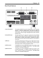
Rear Panel Features
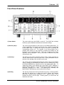
1) Power Entry Module
This contains the DS335's fuse and line voltage selector. Use a 1 amp slow
blow fuse for 100/120 volt operation, and a 1/2 amp fuse for 220/240 volt
operation. To set the line voltage selector for the correct line voltage, first
remove the fuse. Then, remove the line voltage selector card and rotate the
card so that the correct line voltage is displayed when the card is reinserted.
Replace the fuse.
2) Sweep/FSK Output
This output generates a TTL pulse that is synchronous with the DS335's
frequency sweep. When the DS335 is in FSK mode, the output voltage
reflects the present frequency at the FUNCTION output BNC (TTL LOW =
Start Frequency, TTL HIGH = Stop Frequency). The shield of this output is
tied to that of the function output and may be floated up to ±40V relative to
earth ground.
3) FSK Input
The Frequency-Shift Keying input allows the user to toggle between the start
frequency and the stop frequency. The BNC takes a TTL level input. When
the input is low the start frequency is active, and when the input is high the
stop frequency is active. This input is sampled at 10 MHz.
4) GPIB Connector
If the DS335 has the optional GPIB/RS232 interface this connector is used
for IEEE-488.1 and .2 compatible communications. The shield of this
connector is connected to earth ground.
5) RS232 Connector
If the DS335 has the optional GPIB/RS232 interface this connector is used
for RS232 communication. The DS335 is a DCE and accepts 8 bits, no
parity, 2 stop bits at between 300 and 9600 Baud. The shield of this
connector is connected to earth ground.
DS335 Synthesized Function Generator