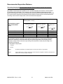
1
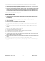
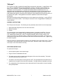
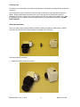
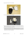
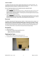
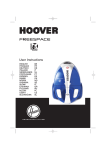
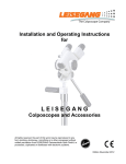
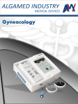
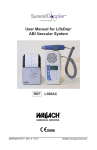
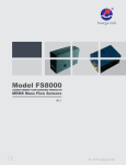
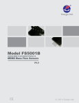
MODEL: SCOPE COLPOSCOPE USER’S MANUAL ZOOMSCOPE™ with TRULIGHT COLPOSCOPE TRISCOPE™ with TRULIGHT COLPOSCOPE REF: 906043-SP-3, 906043-SP-4, 906043-SP-5, 906043-40TU-5, 906150T-4, 906150T-5, 906043-SP-4C, 906043-SP-5C, 906043-40TU-5C, 906150T-4C, 906150T-5C WALLACH SURGICAL DEVICES 95 Corporate Drive Trumbull, CT 06611 USA Phone: (203) 799-2000 Fax: (203) 799-2002 www.wallachsurgical.com EC REP EMERGO EUROPE Molenstraat 15 2513 BH, The Hague The Netherlands IMSC035-DFU • Rev. A • 6/14 Made in the USA This page left blank intentionally Table of Contents Cautions ..........................................................................................................2 ZoomScope Assembly Instructions ...........................................................................2 Optical Head Adjustment .................................................................... 4 Power Zoom and Focus .......................................................................5 Scope Operation ..................................................................................5 Focusing the ZoomScope with Trulight ...............................................5 Video ZoomScope with Trulight, USB .................................................6 TriScope Assembly Instructions ..........................................................................7 Operating Instructions ..........................................................................7 Focusing the TriScope ..........................................................................8 Accessories ..........................................................................................8 Digital Camera Attachment ..........................................................8 Digital Photography .....................................................................8 Teaching Tube ............................................................................9 USB Video Attachment ...............................................................9 Arm Adjustment ....................................................................................11 Electrical ...........................................................................................................11 Illumination .......................................................................................................11 Replacing the Fuses .......................................................................................11 Moving the Colposcope with Trulight ............................................................12 Positioning the ColpoScope with Trulight ....................................................12 Maintenance ...................................................................................................12 Warranty Information ...................................................................................12 Service and Repair .......................................................................................13 Explanation of Symbols ..............................................................................14 Specifications ZoomScope with Trulight Specifications ...............................................15 TriScope Specifications ........................................................................16 For All Scope Colposcope Models ...........................................................17 Classification ........................................................................................17 Environment Conditions .......................................................................17 LED Light Specification ........................................................................17 Wallach Colposcopes EMC Compliance Information..........................18 Guidance and Manufacturer’s Declaration.............................................18 Electromagnetic Emissions ..................................................................18 Electromagnetic Immunity ....................................................................19 Recommended Separation Distance .......................................................21 IMSC035-DFU • Rev. A • 6/14 1 Made in the USA Read all safety information and instructions before using this product! Cautions DO NOT USE IN THE PRESENCE OF FLAMMABLE ANESTHETICS OR ELEVATED OXYGEN LEVELS. UNLOCK CASTERS BEFORE MOVING SCOPE OR UNIT MAY TIP OVER. DO NOT OPERATE PRODUCT IF IT APPEARS TO HAVE BEEN DROPPED OR DAMAGED. OBSERVE PRECAUTIONS FOR ELECTROSTATIC DISCHARGE (ESD) AND ELECTROMAGNETIC INTERFERENCE (EMI) TO AND FROM OTHER EQUIPMENT. LED RADIATION; DO NOT STARE DIRECTLY INTO BEAM. The Wallach family of overhead swing arm colposcopes with Trulight feature Zoom and multi-step magnification models on 4 or 5 leg rolling bases with locking casters. ZoomScope™ The Wallach ZoomScope with Trulight is a multi-purpose microscope for colposcopy. The ZoomScope with Trulight has a continuous Zoom range of magnification from 4.6x to 20x. ASSEMBLY INSTRUCTIONS A. Mobile Floorstand CAUTION: BE SURE THE SYSTEM IS MOUNTED SECURELY IN PLACE TO AVOID PERSONAL INJURY. IMSC035-DFU • Rev. A • 6/14 2 Made in the USA The stand has been sent unassembled for shipping purposes. Only one wrench is needed, and it is taped to the base along with the appropriate hardware. (Allen wrench 5/16”; Wallach Part Number WL111504) To complete assembly, place the scope column in the column mount hole so it is standing upright. Carefully tip the entire unit on its side. Line up the hole underneath the base with the hole in the bottom side of the column and insert the bolt. Tighten using the wrench supplied. A four-or fivelegged base is standard with the ZoomScope with Trulight. B. Electronics Box and Suspension Arm Place the electronics box and suspension arm assembly on the top of the column. The hole in the bottom of the electronics box will fit over the column post. Be sure the white or black Teflon ring is placed over the pin on the column before mounting. IMSC035-DFU • Rev. A • 6/14 3 Made in the USA C. Microscope Head Place the microscope head into the retaining ring with ocular tubes pointed upwards. Hand-tighten the thumbscrew. Remove protective caps from the diopter rings. Gently push the eyepieces into the binocular tubes. Care should be taken to keep eyepieces in an upright position, as they will slip out if the microscope head is turned upside down. Caution: Do not tilt head all the way back as eyepieces can slide out of the binoculars and become damaged. D. Installation of Removable Handlebars for ZoomScope 1. Align the scope as you would to look through the Nikon head in a downward position. 2. The stainless steel mounting brackets are located on the left and right sides of the Nikon head retaining ring. 3. The corresponding handles marked “L” (left) and “R” (right) should be inserted into the mounting brackets. NOTE: The handles are marked on the solid end. 4. The holes in the middle of the retaining brackets allow for two positions. The handles can be mounted either parallel or perpendicular to the microscope head retaining ring. OPTICAL HEAD ADJUSTMENT A. Adjustment To use as an operating microscope, reach behind the fine focus knobs and loosen the locking knob for the microscope head retaining ring. Tilt the retaining ring up towards you and retighten the locking knob. Loosen the thumb screw holding the microscope head in place, rotate the head 180° and retighten. Caution: Care should be taken to keep eyepieces in an upright position, as they will slip out if the microscope head is turned upside down. B. Changing the Eyepieces While holding the microscope head, gently slide the eyepieces from the binocular tubes. To replace, gently push the eyepieces back into the binocular tubes assuring that they are fully seated. NOTE: Do not touch the lenses when handling eyepieces. Eyepieces should be cleaned the same way as any photographic lens. IMSC035-DFU • Rev. A • 6/14 4 Made in the USA C. Magnification Final magnification is determined by multiplying the eyepiece power times the microscope body power times the objective lens power. The Wallach ZoomScope with Trulight is normally shipped with 20x eyepieces and .33x objective lens. Therefore, at the lowest setting of the magnification power knob (0.7), the magnification would be: 20 x 0.7 x .33x = 4.6x power At the highest setting of the magnification power knob (3.0) the final magnification would be: 20 x 3.0 x .33x = 19.8x power POWER ZOOM AND FOCUS Directions for Attaching Optional Foot pedal (used for units purchased with power zoom & focus features): Attach by inserting male connector into female receptacle located at the bottom of the electronics box. SCOPE OPERATION 1. Plug in power cord. 2. Turn ON (I) the master switch. 3. Turn on the white or green light using the switch located on the front of the unit. 4. Turn light illumination knob to appropriate light intensity. This can be adjusted at any time during the procedure. 5. Unlock the casters when moving the colposcope. For transportation of the colposcope, place colposcope head in lowest position to assure stability during transportation. 6. Position the ZoomScope; lock casters in place. 7. See “Focusing” instructions that follow. FOCUSING THE ZOOMSCOPE WITH TRULIGHT 1. Turn both diopter rings on the binocular tubes until the end surface of each ring coincides with the black engraved lines. 2. Looking into the eyepieces, set the distance between the oculars to conform to your interpupillary distance by moving the binocular tubes so that both circular view fields are brought into coincidence. 3. Set the zoom knob to 3x. (If power zoom is available, the footpedal should be used). 4. Adjust the fine focus rack to midway of travel. Position the head at approximately 305 mm (for .33x objective lens) from the target to coarse focus. Rotate the fine focus knobs to bring the target into focus. The fine focus knobs can be tightened or loosened to adjust travel ease by rotating them in opposite directions. If power focus is available, the footpedal must be used for focusing operations. Do not re-adjust fine focus after a clear image is viewed at the 3x zoom magnification. IMSC035-DFU • Rev. A • 6/14 5 Made in the USA 5. Rotate the zoom knob to 0.7x (Footpedal should be used where power zoom is available). 6. Close your right eye; adjust the left diopter ring to bring the target into focus. Close your left eye; adjust the right diopter ring to bring the target into focus. 7. At this point, focusing has been completed. Steps 1 through 7 can be repeated for exact focusing if desired. As long as the scope is not moved out of position, or the fine focus adjustment is not moved, the target will keep its sharpness at all times regardless of the zoom magnification level. VIDEO ZOOMSCOPE WITH TRULIGHT, USB Sentech USB Camera Setup 1. Install Sentech Image Viewing Software (StCamSWare) onto laptop desktop. (See Quick Start Guide IMSC031) 2. Attach Video ZoomScope microscope optical head to laptop via USB cable provided. 3. Turn on Colposcope 4. Double Click on the “STCamSWare” icon on the desktop 5. Using the cursor, choose “Options,” then “Settings”. A window will open at the bottom right of screen. 6. Check the “Auto” boxes next to the Gain and Shutter features. (Mirror image should be set to vertical.) 7. Click on the “Save” button, and then choose “Yes”. 8. Focus to get the desired image on the screen. 9. To capture the image on the screen, choose “Capture” and then “Snap Shot”. 10. A window will open to the right of the main image. 11. To save the image, click to “select” the image with your left mouse button. This will cause a “blue” border to appear around the image of interest. 12. With the mouse over the image, click using the right mouse button and a menu will appear. Select “Save”. 13. The image may be saved in one of four formats: Bitmap, TIFF, JPEG or PNG. 14. Complete the information as you would for any software program and save to a location of your choice. IMSC035-DFU • Rev. A • 6/14 6 Made in the US TriScope™ The TriScope is a highly versatile triple magnification stereoscopic colposcope. A magnification of 8x, 13x, and 21x is obtained with the 3-step magnification changer. The field of view diameters are 24mm, 15mm, and 9mm. A vessel delineation filter (green light) is incorporated to provide clear visualization of vascular patterns. The optical beam splitter permits the attachment of the coobservation tube and photographic accessories for documentation purposes, thereby extending the capability of this instrument from routine gynecologic examinations to gynecologic research. The image obtained through the accessory ports is identical to that viewed through the binocular tubes via the optical beam splitter. Photographic documentation capabilities include video and digital photography. High power white light emitting diodes allow user to view images in pure white light. A green LED will be used to pick up blood vessels. The TriScope is mounted on a 4 or 5-legged base for stability and maneuverability. ASSEMBLY INSTRUCTIONS The TriScope has three parts. The following are easy assembly instructions for the new colposcope. 1. Optical Head with Eyepieces on the arm with Control Box 2. Mobile Floorstand 3. Column The stand has been sent unassembled for shipping purposes. Assembly is not difficult. Only one wrench is needed, and it is taped to the base along with the appropriate hardware. (Allen wrench 5/16”; Wallach Part Number WL111504) To complete assembly, place the scope column in the column mount hole so it is standing upright. Carefully tip the entire unit on its side. Line up the hole underneath the base with the hole in the bottom side of the column and insert the bolts. Tighten using the wrench supplied. Place the control box optical head and suspension arm assembly onto the top of the column. The hole in the bottom of the control box will fit over the column post. Be sure the white Teflon ring is placed over the pin on the column before mounting. OPERATING INSTRUCTIONS To operate the TriScope: 1. Set the Optical System to the desired height. 2. Plug the cord into a standard wall outlet. 3. The master power switch is located on the side panel of the control box assembly. This switch turns the main power source ON or OFF. 4. The switch on the front panel turns the light ON or OFF. The light adjustment Illumination knob is located on the front panel of the control box assembly. The light intensity is adjusted by the knob. 5. For transportation of the colposcope, place colposcope head in lowest position to assure stability during transportation. IMSC035-DFU • Rev. A • 6/14 7 Made in the USA FOCUSING THE TRISCOPE 1. Set the binocular eyepieces to “0” and adjust them to the proper interpupillary distance. 2. Peering through the eyepieces, move the arm of the TriScope backward or forward to get a “rough” focus on the target (12” or 300 mm from objective lens to target). 3. Focus at the highest magnification. Focusing at this magnification is extremely critical and leads to perfect focusing for all other magnification levels. Set the fine focus by rotating the fine focus knobs until the rack is at the midpoint. Thereafter, the physician only has to switch to another magnification without the need to refocus the instrument. If the instrument is repositioned, however, the procedure must be repeated. 4. To set the image of the target in each eye, turn the eyepieces themselves. (Notice that the eyepieces are calibrated to help refocus the eyepiece setting next time.) 5. Focusing is complete. ACCESSORIES Your TriScope split beam colposcope is designed to provide the ultimate ease in colposcopic digital photography. The complete system of photographic equipment for digital pictures has been created to allow even the novice photographer to clearly document visual observations for patient files. No special techniques are required and there is no need to dismount the camera when photography is not intended. Camera focusing is achieved through the TriScope oculars. Digital Camera Attachment 1. Remove camera lens cover. Attach the adaptor mounting ring to the camera by aligning the red mark on the ring with the red dot on the camera lens mount. Then turn the ring until a click is heard when attachment is secure. 2. Remove the black cap on the digital camera photo adaptor by loosening the stainless steel set screw. Place the end of the adaptor mounting ring into the photo adaptor and retighten the set screw. 3. Attach the digital camera photo adaptor to the colposcope accessory port. The camera may be mounted on either the right or the left accessory port. 4. Remove the protective accessory port cap. Guide slots on the photo adaptor permit the positioning of the camera. Align the slots in the photo adaptor with the guides on the adaptor ring. Slide the adaptor ring over the photo adaptor and tighten gently in a counterclockwise direction. DO NOT OVER TIGHTEN. 5. The camera is now ready for use. Digital Photography Refer to instruction manual for the digital camera. Looking through the oculars, adjust the instrument for focus and composition. When the desired image is obtained, press the shutter release button on the camera to make the exposure. IMSC035-DFU • Rev. A • 6/14 8 Made in the USA Teaching Tube For teaching or co-observation, the teaching tube provides a second party viewing head as an optional accessory. The teaching tube may be mounted on either the right or left accessory port provided on the beam splitter. Remove the protective accessory port cap. Guide slots on the teaching tube allow for positioning of the unit. Align the slots on the teaching tube with the guides on the adaptor ring. Slide the adaptor ring over the teaching tube and tighten gently in a counterclockwise direction. DO NOT OVER TIGHTEN. USB Video Attachment There is a video camera C-Mount Adaptor available to attach any analog or USB camera. (Please note that only one side of the C-Mount Adaptor can attach to the TriScope.) The instructions are as follows: 1. Attach the mounting ring to the camera. IMSC035-DFU • Rev. A • 6/14 9 Made in the USA 2. Attach the entire camera to the C-mount Adaptor. 3. Then attach the C-Mount Adaptor to the TriScope. 4. Plug in the S video cable if you have an analog camera. Next, plug in the power supply. Then plug the power supply into the wall. For a USB camera, plug the USB cable into the camera and the other end into the USB port on the laptop or PC. 5. After the C-Mount has been attached to the colposcope, the camera needs to be oriented so that the image on the monitor is the same as that viewed through the optical head. On the C mount, loosen the large silver knurled ring. Rotate the camera head until the image on the monitor is the same as what is viewed through the optical head. Once it is aligned properly, rotate the knurled ring clockwise until it is locked in a snug position. IMSC035-DFU • Rev. A • 6/14 10 Made in the USA ARM ADJUSTMENT Your Wallach Colposcope with Trulight is adjusted and tested just prior to leaving the factory. The colposcope arm may be moved into any position and should remain in place. However, further arm adjustments may become necessary. A 5/64 Allen wrench is included. For Arm Tightening Adjustment (see laminated instruction attached to pole) 1. Tighten Up & Down Motion of the Arm Find set screws (two pair) on the long part of the arm. Tighten these set screws 1/8 turn at a time with a 5/64 Allen wrench by turning the screws clockwise. The arm movement may be set to a desired tension by using these screws. All retaining screws should be tightened the same amount (refer to instruction card on column). 2. Tighten Back & Forth Motion of the Arm Find set screws on the short part of the arm. These screws should be tightened 1/ 8 turn at a time with a 5/64 Allen wrench by turning clockwise. The back and forth motion may be set to a desired tension by using these screws. All set screws should be tightened the same amount. Electrical The Wallach Colposcope with Trulight requires a 100-240V ~ 50-60 Hz power source to operate. It is supplied through a 2.5 meter medical grade detachable cord in standard 120 volt versions. For your safety, assure that your electrical outlets meet code regulations. The master power switch is located on the side panel of the electronics box assembly. This switch turns the main power source on or off. The switch on the front panel turns the light from white to green and back. (The middle setting is for “O”, the IEC symbol for OFF.) The knob on the front panel controls the light intensity. Illumination a. LED Light Frequency b. Dominant Wave Length for Green Light Emitting Diode Minimum value 530 nm (nanometers) Maximum value 535 nm (nanometers) Replacing the Fuses 1. Shut OFF (O) the master switch and unplug power cord. 2. The electronics box contains two fuses beneath the power socket. IMSC035-DFU • Rev. A • 6/14 11 Made in the USA 3. To remove, pull out the drawer beneath the power socket. 4. Remove the blown fuse from the holder and replace with a 2 amp, 5 mm x 20 mm Fast Blow Fuse 5. Push the fuse holder back into the electronics box. Moving the Colposcope with Trulight To move the Colposcope with Trulight from room to room, release the locking casters, unplug the power cord from the outlet and position the microscope head away from the direction of movement. Grasp the column with one hand and the scope with the other and push the colposcope to its new location. For added stability, it is best to position the suspension arm directly over any one of the legs as it is being moved. Positioning the Colposcope with Trulight Set the Wallach Colposcope with Trulight in front of the examination table so that one leg is perpendicular to the table and in line with the suspension arm. Each leg is equipped with a locking caster. To lock the caster, push down. To unlock the caster, push up. Maintenance PRECAUTION: DO NOT IMMERSE EQUIPMENT COMPONENTS IN LIQUID; UNPLUG BEFORE CLEANING; DRY BEFORE USE. Clean the lenses and protective light covers with silicone-treated lens tissue paper ONLY. The colposcope finish is a high-gloss enamel and may be wiped down with a disinfectant. Keep the instrument clean and dust-free. When the colposcope is not in use, replace protective covers. Warranty Information Wallach Trulight products are warranted by Wallach Surgical Devices to be free from defects in material and workmanship for a period of seven years. During this period, Wallach Surgical Devices will, at its option and without charge, either repair or replace any part or assembly of parts found to be defective in material and workmanship. Repairs are to be accomplished by a Certified Wallach Surgical Devices Repair Technician. In the event that the unit is tampered with by unauthorized personnel prior to the end of the warranty, the warranty is considered NULL and VOID, This warranty does not apply to the following: 1. Product which has been subject to misuse, abuse, negligence or accident. 2. Defects or damage directly or indirectly caused by installation or service of the product by unauthorized personnel and/or the use of unauthorized replacement parts. 3. Improper use of cleaning methods or chemicals which damages equipment. 4. Peripheral equipment that is covered by the manufacturer’s warranty. IMSC035-DFU • Rev. A • 6/14 12 Made in the USA Service and Repair In the event your Colposcope with Trulight becomes inoperative, please make the following checks before calling the factory: 1. Check that the unit is plugged into a working wall receptacle. 2. Check for a blown fuse. WARNING! Remove AC Power from the colposcope before checking for a blown fuse. If your colposcope is still inoperative, remove the unit from use, contact qualified factory service personnel at (866)-928-3211. If a repair is needed, equipment must be sanitized before it is returned to the factory and carefully packaged in a protective carton. It is not necessary to ship the base and column unless there is a problem with them. All shipments must be made via pre-paid parcel post or U.S. Mail. COD packages will not be accepted. Return carton to: SURGICAL DEVICES Attention: Repair Department 95 Corporate Drive Trumbull, CT 06611 USA Phone: (203) 799-2000 Fax: (203) 799-2002 IMSC035-DFU • Rev. A • 6/14 13 Made in the USA Explanation of Symbols REF SN Reorder Number Serial Number Consult instructions for use U.S. Federal law restricts this device to sale by or on the order of a physician. For professional use only Product conforms to the Medical Device Directive 93/42/EEC EC REP Authorized Representative in the European Community. Manufacturer AC Main Power OFF AC Main Power ON Shock Hazard Pinch Point IMSC035-DFU • Rev. A • 6/14 14 Made in the USA Specifications ZOOMSCOPE WITH TRULIGHT SPECIFICATIONS Overall height 160.02 cm Height of column Overall weight 101.6 cm (116.8 cm and 139.7 cm also available) 27.9 kg (Basic ZoomScope without accessories) Center of column to end of leg 39.37 cm Center of column to center of microscope with boom suspended horizontally Height of microscope from depressed position of suspension to floor 50.80 cm Power Requirements 100-120V/200-240V AC, 50/60 Hz, 100VA Fused power input lamp 2.0 amps Fuse Rating: F2.0A/250V~ Power cord 2.44 meter medical grade power cord with North American 120 VAC plug Working Distance 285 mm Dominant Wave Length for Green Light Emitting Diode Minimum value 525 nm (nanometers) Maximum value 535 nm (nanometers) IMSC035-DFU • Rev. A • 6/14 67.31 cm. At extreme position of suspension: 116.8 cm (with short column) 15 Made in the USA TRISCOPE SPECIFICATIONS Type Warranty Power Requirements Mounting Systems 3-Step Magnification with beam splitter 7 Year 100-120V/200-240V AC, 50/60 Hz, 100VA 4 or 5-Leg Rolling Base (4 is standard) Standard Optical Configurations Objective Lens (Working Distance) Total Magnification Field of View Depth of Field Ocular (Eyepieces) Diopter Adjustment Interpupillary Range Tilt of Viewing Head Binocular Tube Design Binocular Tube Lengths Magnification Changer Factors Vessel Delineation Filter 300mm 8x, 13x, & 21x 8.5x = 23.4mm, 13.6x =14.6mm, 21.3x = 9.4mm 8x =3.1mm, 13.6x =1.2mm, 21.3x = 0.9mm 16x Highpoint, with locking diopters Independent adjustment with position locking -6/+4 54mm to 80mm 59 degrees Straight 160mm 1.0x, 1.6x, 2.5x Yes Illumination System Illumination Light Emitting Diodes (LED) (5000/7000 degrees Kelvin) Green LED for blood vessel delineation. Photographic Capabilities Digital, Video Yes Options Teaching Tube IMSC035-DFU • Rev. A • 6/14 Yes 16 Made in the USA For All Scope Colposcope Models Classification Model Scope with Trulight Colposcopes Safety Class I ALL models of Colposcopes have no Applied Parts. Do not get fluid into the Colposcope. Should any liquid or solid object fall into the unit, unplug the unit and call Technical Support (866) 928-3211. The LED Model Colposcopes are suitable for continuous operation. The LED Model Colposcopes are classified as normal equipment (IPX0) according to protection against ingress of water. Environment Conditions Use: Environmental Temperature: Relative Humidity: Air Pressure: between +10 °C and +40 °C between 10% and 90 % between 700 hPa and 1060 hPa Shipping and Storage: Environmental Temperature: Relative Humidity: Air Pressure: between +10 °C and +40 °C between 10% and 90% between 700 hPa and 1060 hPa LED Light Specification White LED: Correlated Color Temperature Rendering Index Radiometric Power Total Irradiance 6000K 70 80 mW 4.284 W/m2 at max intensity Green LED: Average Wavelength Radiometric Power Total Irradiance IMSC035-DFU • Rev. A • 6/14 530 nM 80 mW 0.795 W/m2 at max intensity 17 Made in the USA Wallach Colposcopes EMC Compliance Information MEDICAL ELECTRICAL EQUIPMENT needs special precautions regarding EMC and needs to be installed and put into service according to the EMC information provided in the ACCOMPANYING DOCUMENTS. Portable and mobile RF communications equipment can affect MEDICAL ELECTRICAL EQUIPMENT. Guidance and Manufacturer’s Declaration – Electromagnetic Emissions The Wallach Colposcope is intended for use in the electromagnet environment specified below. The customer or the end user of the Wallach Colposcope should assure that it is used in such an environment. Emissions Test Compliance RF emissions Group 1 CISPR 11 Electromagnetic Enviroment- Guidance Wallach Colposcopes use RF energy only for it internal function. Therefore, its RF emissions are very low and are not likely to cause any interference in nearby electronic equipment. RF emissions Class A CISPR 11 Harmonic emissions Class A IEC 61000-3-2 Voltage fluctuations/ Flicker emissions Wallach Colposcopes are suitable for use in all establishments, including domestic establishments and those directly connected to the public low-voltage power supply network that supplies buildings used for domestic purposes. Complies IEC 61000-3-3 IMSC035-DFU • Rev. A • 6/14 18 Made in the USA Guidance and Manufacturer’s Declaration – Electromagnetic Immunity The Wallach Colposcopes are intended for use in the electromagnet environment specified below. The customer or the end user of the Wallach Colposcopes should assure that it is used in such an environment. IEC 60601 Test Level Immunity Test Electromagnetic discharge (ESD) Compliance Level +6 kV contact +6 kV contact +8 kV air +8 kV air Electrical fast transient/burst +2 kV for power supply lines +2 kV for power supply lines IEC 61000-4-4 +1 kV for input/output lines +1 kV for input/output lines Surge +1 kV differential mode +1 kV differential mode IEC 61000-4-5 +2 kV common mode IEC 61000-4-2 Electromagnetic Environmental Guidance Floors should be wood, concrete or ceramic tile. If floors are covered with synthetic material, the relative humidity should be at least 30%. Mains power quality should be that of a typical commercial or hospital environment. Mains power quality should be that of a typical commercial or hospital environment. +2 kV common mode Voltage dips, short interruptions and voltage variations on power supply input lines IEC 61000-4-11 Power frequency (50/60 Hz) magnetic field < 5% UT (> 95% dip in UT) for 0.5 cycle < 5% UT (> 95% dip in UT) for 0.5 cycle 40% UT (60% dip in UT) for 5 cycles 40% UT (60 % dip in UT) for 5 cycles 70% UT (30% dip in UT) for 25 cycles 70% UT (30% dip in UT) for 25 cycles < 5% UT (> 95% dip in UT) for 5 sec < 5% UT (> 95% dip in UT) for 5 sec 3 A/m 3 A/m Mains power quality should be that of a typical commercial or hospital environment. If the user of the Wallach Colposcope requires continued operation during power mains interruptions, it is recommended that the Wallach Colposcope be powered from an uninterruptible power supply or a battery. Power frequency magnetic fields should be at levels characteristic of a typical location in a typical commercial or hospital environment. IEC 61000-4-8 NOTE: UT is the a.c. mains voltage prior to application of the test level. In this case 230 V. IMSC035-DFU • Rev. A • 6/14 19 Made in the USA Guidance and Manufacturer’s Declaration – Electromagnetic Immunity (continued) Immunity Test IEC 60601 Test Level Complianc e Level Electromagnetic Environmental – Guidance [Note 1 and 2] Portable and mobile RF communications equipment should be used no closer to any part of the Wallach Colposcope, including cables, than the recommended separation distance calculated from the equation applicable to the frequency of the transmitter. Conducted RF 3 Vrms IEC 61000-4-6 150 kHz to 80 MHz Radiated RF 3 V/m IEC 61000-4-3 80 MHz to 2.5 GHz 3V 3 V/m Recommended separation distance 3. 5 d P V1 3.5 d P 80 MHz to 800 MHz E1 7 d P 800 MHz to 2.5 GHz E1 where P is the maximum output power rating of the transmitter in watts (W) according to the transmitter manufacturer and d is the recommended separation distance in meters (m). Field strengths from fixed RF transmitters, as determined by an electromagnetic site survey,a should be less than the compliance level in each frequency range.b Interference may occur in the vicinity of equipment marked with the following symbol: NOTE 1: At 80 MHz and 800 MHz, the separation distance for the higher frequency range applies. NOTE 2: These guidelines may not apply in all situations. Electromagnetic propagation is affected by absorption and reflection from structures, objects and people. a b Field strengths from fixed transmitters, such as base stations for radio (cellular/cordless) telephones and land mobile radios, amateur radio, AM and FM radio broadcast and TV broadcast cannot be predicted theoretically with accuracy. To assess the electromagnetic environment due to fixed RF transmitters, an electromagnetic site survey should be considered. If the measured field strength in the location in which the Wallach Colposcope are used exceeds the applicable RF compliance level above, the Wallach Colposcope should be observed to verify normal operation. If abnormal performance is observed, additional measures may be necessary, such as reorienting or relocating the Wallach Colposcope. Over the frequency range 150 kHz to 80 MHz, field strengths should be less than 3 V/m. IMSC035-DFU • Rev. A • 6/14 20 Made in the USA Recommended Separation Distance This section discusses the Recommended Separation Distance between portable and mobile RF communications equipment and the Wallach Colposcopes. The Wallach Colposcopes are intended for use in an electromagnetic environment in which radiated RF disturbances are controlled. The customer or the user of the Wallach Colposcopes can help prevent electromagnetic interference by maintaining a minimum distance between portable and mobile RF communications equipment (transmitters) and the Wallach Colposcopes as recommended below, according to the maximum output power of the communications equipment. Separation distance according to frequency of transmitter (Meters) [Note 1 and 2] Rated maximum output power of transmitter (Watts) 0.01 0.1 1 10 100 150 kHz to 80 MHz 80 MHz to 800 MHz 3.5 d P v1 3.5 d P E1 0.1167 0.3689 1.1667 3.6894 11.667 0.1167 0.3689 1.1667 3.6894 11.667 800 MHz to 2.5 GHz 7 d P E1 0.2333 0.7379 2.3333 7.3789 23.333 For transmitters rated at a maximum output power not listed above, the recommended separation distance d in meters (m) can be estimated using the equation applicable to the frequency of the transmitter, where P is the maximum output rating of the transmitter in watts (W) according to the transmitter manufacturer. For the Wallach Colposcopes: v1 = 3 Vrms E1 = 3 V/m NOTE 1: At 80 MHz and 800 MHz, the separation distance for the higher frequency range applies. NOTE 2: These guidelines may not apply in all situations. Electromagnetic propagation is affected by absorption and reflection from structures, objects and people. IMSC035-DFU • Rev. A • 6/14 21 Made in the USA This page left blank intentionally IMSC035-DFU • Rev. A • 6/14 Made in the USA