1
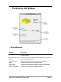
Detector ACE User Guide 300-002-01 Detector ACE User Guide Page i © Copyright 2014. All rights reserved. No part of this document may be copied or reproduced in any form without the written consent of the author. Additionally, this document is not to be passed to or discussed with third parties without the prior written permission of the author. The information contained herein is believed to be accurate; however, no responsibility is assumed for inaccuracies. Users of the described products and documentation should exercise their own independent judgment to evaluate the suitability of the products and documentation for their particular application. The author does not accept any liability arising from the application or use of the product or this documentation. iStud is a registered trademark of Sentech Systems Pty Ltd. All other trademarks and registered trademarks are the property of their respective holders. Errata The author believes that this document is accurate, and it has been carefully checked for accuracy. However sometimes errors do appear in the published version. If you believe that there is a mistake in this document then please contact the author. E.&O.E. 300-002-01 Detector ACE User Guide Page ii Revision History Version Date Revision Description 01 11-Feb-2014 Initial release, covers Detector ACE v1.01 300-002-01 Detector ACE User Guide Page iii Table of Contents 1. Introduction .............................................................................................................2 Detector ACE ..............................................................................................................................2 Installing Detector ACE .............................................................................................................2 The Detector ACE Window ................................................................................................... 3 Window Elements ................................................................................................................................. 3 2. Getting Started ........................................................................................................4 Physical Connection ............................................................................................................ 4 Connection Settings ............................................................................................................. 5 COM Port Settings ................................................................................................................................ 5 Establishing the Connection................................................................................................ 6 Troubleshooting .................................................................................................................................... 6 USB Troubleshooting Procedure .......................................................................................................... 7 3. Configuring and Viewing ........................................................................................8 Main Tab................................................................................................................................ 8 Configuration Tab ................................................................................................................. 9 Detection Parameters ........................................................................................................................... 9 Switched Output .................................................................................................................................. 10 Write Configuration ............................................................................................................................. 11 Status Tab ........................................................................................................................... 12 Detections Tab .................................................................................................................... 13 Line Interface Tab ............................................................................................................... 14 300-002-01 Detector ACE User Guide Page 1 1. Introduction iStud Vehicle Detectors are magnetometer based detectors that provide a yes/no indication of vehicle presence. Indication is by way of an open collector output that is toggled when a vehicle is present. iStud Vehicle Detectors are microprocessor based and store a variety of configuration parameters and status indicators internally in non-volatile memory. These parameters and indicators can be viewed and adjusted by using the proprietary Detector ACE – a Microsoft Windows based application that is connected to the iStud Vehicle Detector using a Line Interface Card. This user guide explains how to use the Detector ACE application to manage and configure iStud Vehicle Detectors. Detector ACE The Detector ACE application provides configuration and diagnostic facilities for iStud Vehicle Detectors. It has a standard Windows dialog interface that will be intuitive to most users. Detector ACE is not essential for the day-to-day operation of the iStud system. It is only used when vehicle detectors need to be configured or if a problem needs to be diagnosed. Installing Detector ACE The Detector ACE application can be installed on most PCs / notebooks running Microsoft Windows XP or later, including Windows Vista and Windows 7. Prior to installing, it is recommended that all other running applications be closed. To commence installation, simply double-click the supplied setup.exe file and follow the prompts. 300-002-01 Detector ACE User Guide Page 2 The Detector ACE Window Window Elements Element Description Line Interface status Shows if a Line Interface Card is connected and communicating with the software. Line Interface action buttons Used to adjust PC port settings and re-establish the connection to the Line Interface Card. Vehicle Detector status Shows if a Vehicle Detector is correctly connected and communicating with the Line Interface Card. Viewing tabs Toggles between alternate pages of information and settings. Version information Confirms the version of the installed software. 300-002-01 Detector ACE User Guide Page 3 2. Getting Started This chapter describes how to configure the Detector ACE to connect to a Vehicle Detector and carry out some basic operations. Physical Connection PC with Detector ACE Line Interface Card RS-232 Serial Vehicle Detector iStud Bus A standard RS-232 serial COM port is used on the host PC for the connection to the Line Interface Card. If the PC does not have a built-in serial port then a USB serial adapter can be used. This connection is labelled ‘COMMS’ on the Line Interface Card and uses an RJ-45 to DB-9 cable. The connection between the Line Interface Card and the Vehicle Detector is known as the ‘iStud Bus’. It uses 3 wires to carry both power and data to the detector. Connect both the RS-232 Serial and iStud Bus cables and then apply power to the Line Interface Card. 300-002-01 Detector ACE User Guide Page 4 Connection Settings The connection settings are configured during the first use of Detector ACE. Once set, they are stored on the PC and do not need to be changed. COM Port Settings Clicking the ‘Settings’ button on the Main tab shows the following dialog: Parameter Setting COM Port Choose a COM port from the drop-down list. All COM ports available on the PC are shown in the list. USB adapters can be identified by viewing the list with the adapter disconnected and then connecting the adapter and comparing the difference. Bit Rate Must agree with the Line Interface Card’s rate. A value of 57600 is currently used. Click ‘OK’ to apply the settings or ‘Cancel’ to close the dialog without saving. Note If using a USB serial adapter then be sure to connect it to the same USB port on the PC every time that the Detector ACE is used. This is because Windows associates the COM port number with specific USB port / adapter combinations. If you wish to connect your USB serial adapter to a different port than the one used previously, then simply change the COM Port setting as shown above. 300-002-01 Detector ACE User Guide Page 5 Establishing the Connection Once the connection settings have been made, click the ‘Refresh’ button on the Main tab. If the connection is successful then the following indication will be seen and some additional tabs will appear at the bottom of the window. Troubleshooting If the above indication is not seen then the following action can be taken. Indication Description / Action The link from PC to Line Interface Card (LIC) is not working. Check that all cables are connected Check LIC power supply Ensure that LEDs on the front of the LIC flash when power is first applied to LIC Check that COM Port settings are correct If using a USB serial adapter, use the USB Troubleshooting Procedure below. The link from PC to Line Interface Card (LIC) is working; however the iStud Bus between the LIC and Vehicle Detector is not operational. Check that the iStud Bus cable is connected Check that the Vehicle Detector has been completely isolated from all other equipment and is only connected to the LIC 300-002-01 Detector ACE User Guide Page 6 Both the link from PC to Line Interface Card (LIC) and the iStud Bus are operational, however more than one Vehicle Detector is connected to the iStud Bus. Only connect one Vehicle Detector to the iStud Bus at a time USB Troubleshooting Procedure If using a USB serial adapter, the correct COM Port can be verified as follows: 1. From the Main tab, click ‘Settings’ and then open the COM Port pull-down list. 2. Note down all COM Ports and then click ‘Cancel’. 3. Disconnect the USB serial adapter from the PC. 4. From the Main tab, click ‘Settings’ and then open the COM Port pull-down list. 5. Determine which COM Port is missing from the list made in step 2 above. The missing port number is the one that should be used when the USB adapter is connected to the same USB port on the PC (the COM Port number will differ if the USB adapter is connected to a different port on the PC). 6. If no missing COM Port was found in step 5 then either the USB adapter or USB port on the PC is faulty. Check the USB port on the PC with another device (such as a USB flash memory stick) for correct operation. Try the USB serial adapter in a different USB port. Select one that is directly on the PC; do not use an external USB hub. 300-002-01 Detector ACE User Guide Page 7 3. Configuring and Viewing The Detector ACE application is arranged as a logical series of pages which are selected by clicking on tabs at the bottom of the window. Each of these pages is explained in greater detail below. Main Tab The Main tab shows the status of the two physical/logical links: PC to Line Interface Card Line Interface Card to Vehicle Detector It also has two Line Interface action buttons which allow the link parameters to be adjusted. Their operation is described in section 2 above. 300-002-01 Detector ACE User Guide Page 8 Configuration Tab Selecting the “Configuration” tab shows the following page: Detection Parameters The detection parameters determine how the Vehicle Detector responds to changes in the surrounding magnetic field and are described below. Parameter Setting Gain Controls the analogue front end amplification of the signal from the magnetometer. Discrete values between 0.5 and 2.0 can be selected from the pull-down list. Detect Threshold Sets the magnitude change required (away from the baseline value) before a vehicle detection event is triggered. Counts to Trigger The number of consecutive samples for which the magnetic signal must exceed the Detect Threshold before a vehicle detection event is triggered. 300-002-01 Detector ACE User Guide Page 9 Release Threshold Hold Over Counter Specifies the minimum magnitude required to continue a detection event once the event has commenced. This value is usually set lower than the Detect Threshold. Specifies the time period for which the magnetic magnitude must drop below the Release Threshold to end a detection event. Baseline Rate No Detect The rate at which the baseline magnetic value changes (in response to background changes) when the Vehicle Detector is in its idle state (no detection event in progress). Baseline Rate Detect The rate at which the baseline magnetic value changes (in response to background changes) when the Vehicle Detector is in its triggered state (detection event in progress). Usually set much lower than Baseline Rate No Detect. Recalibration Timeout Setting a value greater than 0 will cause the Vehicle Detector to perform an automatic recalibration in the event that a detection event has persisted for a time greater than the number of seconds specified. Use with caution; usually set to 0. Switched Output The Switched Output settings control how each detection event is signalled to the connected equipment. Parameter Setting Output Type One of the following: Continuous Output is held in the active state for the entire time while a detection event is in progress. Timed Output is toggled to the active state at the start of a detection event and then returns to the idle state after the period specified in Duration elapses. Duration The period, in seconds, for which the output remains active when an event occurs. Applies only when Output Type is set to “Timed”. Output Polarity Desired output when a vehicle is detected. Can be either “Active High” or “Active Low”. Enable Manual Output Control Allows the output to be forced to a specific state. For testing purposes only. Output State State to be used during Manual Output Control 300-002-01 Detector ACE User Guide Page 10 Write Configuration To save all of the settings on the Configuration tab to the Vehicle Detector, click the ‘Write Configuration’ button. All of the settings are saved to the Vehicle Detector’s nonvolatile memory. Once the saving process has been successfully completed, a confirmation appears briefly at the bottom of the window as shown: 300-002-01 Detector ACE User Guide Page 11 Status Tab Selecting the “Status” tab shows the following page: The Status tab shows status information from the connected vehicle detector. This tab only appears once a vehicle detector is successfully connected to the iStud Bus. 300-002-01 Detector ACE User Guide Page 12 Detections Tab Selecting the “Detections” tab shows the following page: The Detections tab can be helpful in diagnosing vehicle detection problems. It shows summary information along with magnetic waveform images for vehicle detection events. 300-002-01 Detector ACE User Guide Page 13 Line Interface Tab Selecting the “Line Interface” tab shows the following page: The Line Interface tab can be helpful in diagnosing communication problems. It is divided into two sections. The upper section shows a number of internal parameters from the Line Interface Card, while the lower section shows the messages being sent and received on the RS232 serial interface. You may be asked to provide a copy of this information when calling for technical support. 300-002-01 Detector ACE User Guide Page 14